EP3564503B1 - Verfahren zur temperaturermittlung eines elektrisch beheizbaren katalysators - Google Patents
Verfahren zur temperaturermittlung eines elektrisch beheizbaren katalysators Download PDFInfo
- Publication number
- EP3564503B1 EP3564503B1 EP19167837.4A EP19167837A EP3564503B1 EP 3564503 B1 EP3564503 B1 EP 3564503B1 EP 19167837 A EP19167837 A EP 19167837A EP 3564503 B1 EP3564503 B1 EP 3564503B1
- Authority
- EP
- European Patent Office
- Prior art keywords
- catalytic converter
- temperature
- electrically heatable
- heating resistor
- resistance
- Prior art date
- Legal status (The legal status is an assumption and is not a legal conclusion. Google has not performed a legal analysis and makes no representation as to the accuracy of the status listed.)
- Active
Links
Images


Classifications
-
- F—MECHANICAL ENGINEERING; LIGHTING; HEATING; WEAPONS; BLASTING
- F01—MACHINES OR ENGINES IN GENERAL; ENGINE PLANTS IN GENERAL; STEAM ENGINES
- F01N—GAS-FLOW SILENCERS OR EXHAUST APPARATUS FOR MACHINES OR ENGINES IN GENERAL; GAS-FLOW SILENCERS OR EXHAUST APPARATUS FOR INTERNAL-COMBUSTION ENGINES
- F01N3/00—Exhaust or silencing apparatus having means for purifying, rendering innocuous, or otherwise treating exhaust
- F01N3/08—Exhaust or silencing apparatus having means for purifying, rendering innocuous, or otherwise treating exhaust for rendering innocuous
- F01N3/10—Exhaust or silencing apparatus having means for purifying, rendering innocuous, or otherwise treating exhaust for rendering innocuous by thermal or catalytic conversion of noxious components of exhaust
- F01N3/18—Exhaust or silencing apparatus having means for purifying, rendering innocuous, or otherwise treating exhaust for rendering innocuous by thermal or catalytic conversion of noxious components of exhaust characterised by methods of operation; Control
- F01N3/20—Exhaust or silencing apparatus having means for purifying, rendering innocuous, or otherwise treating exhaust for rendering innocuous by thermal or catalytic conversion of noxious components of exhaust characterised by methods of operation; Control specially adapted for catalytic conversion
- F01N3/2006—Periodically heating or cooling catalytic reactors, e.g. at cold starting or overheating
- F01N3/2013—Periodically heating or cooling catalytic reactors, e.g. at cold starting or overheating using electric or magnetic heating means
- F01N3/2026—Periodically heating or cooling catalytic reactors, e.g. at cold starting or overheating using electric or magnetic heating means directly electrifying the catalyst substrate, i.e. heating the electrically conductive catalyst substrate by joule effect
-
- F—MECHANICAL ENGINEERING; LIGHTING; HEATING; WEAPONS; BLASTING
- F01—MACHINES OR ENGINES IN GENERAL; ENGINE PLANTS IN GENERAL; STEAM ENGINES
- F01N—GAS-FLOW SILENCERS OR EXHAUST APPARATUS FOR MACHINES OR ENGINES IN GENERAL; GAS-FLOW SILENCERS OR EXHAUST APPARATUS FOR INTERNAL-COMBUSTION ENGINES
- F01N11/00—Monitoring or diagnostic devices for exhaust-gas treatment apparatus
- F01N11/002—Monitoring or diagnostic devices for exhaust-gas treatment apparatus the diagnostic devices measuring or estimating temperature or pressure in, or downstream of the exhaust apparatus
-
- F—MECHANICAL ENGINEERING; LIGHTING; HEATING; WEAPONS; BLASTING
- F01—MACHINES OR ENGINES IN GENERAL; ENGINE PLANTS IN GENERAL; STEAM ENGINES
- F01N—GAS-FLOW SILENCERS OR EXHAUST APPARATUS FOR MACHINES OR ENGINES IN GENERAL; GAS-FLOW SILENCERS OR EXHAUST APPARATUS FOR INTERNAL-COMBUSTION ENGINES
- F01N11/00—Monitoring or diagnostic devices for exhaust-gas treatment apparatus
- F01N11/002—Monitoring or diagnostic devices for exhaust-gas treatment apparatus the diagnostic devices measuring or estimating temperature or pressure in, or downstream of the exhaust apparatus
- F01N11/005—Monitoring or diagnostic devices for exhaust-gas treatment apparatus the diagnostic devices measuring or estimating temperature or pressure in, or downstream of the exhaust apparatus the temperature or pressure being estimated, e.g. by means of a theoretical model
-
- F—MECHANICAL ENGINEERING; LIGHTING; HEATING; WEAPONS; BLASTING
- F01—MACHINES OR ENGINES IN GENERAL; ENGINE PLANTS IN GENERAL; STEAM ENGINES
- F01N—GAS-FLOW SILENCERS OR EXHAUST APPARATUS FOR MACHINES OR ENGINES IN GENERAL; GAS-FLOW SILENCERS OR EXHAUST APPARATUS FOR INTERNAL-COMBUSTION ENGINES
- F01N3/00—Exhaust or silencing apparatus having means for purifying, rendering innocuous, or otherwise treating exhaust
- F01N3/08—Exhaust or silencing apparatus having means for purifying, rendering innocuous, or otherwise treating exhaust for rendering innocuous
- F01N3/10—Exhaust or silencing apparatus having means for purifying, rendering innocuous, or otherwise treating exhaust for rendering innocuous by thermal or catalytic conversion of noxious components of exhaust
- F01N3/18—Exhaust or silencing apparatus having means for purifying, rendering innocuous, or otherwise treating exhaust for rendering innocuous by thermal or catalytic conversion of noxious components of exhaust characterised by methods of operation; Control
- F01N3/20—Exhaust or silencing apparatus having means for purifying, rendering innocuous, or otherwise treating exhaust for rendering innocuous by thermal or catalytic conversion of noxious components of exhaust characterised by methods of operation; Control specially adapted for catalytic conversion
- F01N3/2006—Periodically heating or cooling catalytic reactors, e.g. at cold starting or overheating
- F01N3/2013—Periodically heating or cooling catalytic reactors, e.g. at cold starting or overheating using electric or magnetic heating means
-
- F—MECHANICAL ENGINEERING; LIGHTING; HEATING; WEAPONS; BLASTING
- F01—MACHINES OR ENGINES IN GENERAL; ENGINE PLANTS IN GENERAL; STEAM ENGINES
- F01N—GAS-FLOW SILENCERS OR EXHAUST APPARATUS FOR MACHINES OR ENGINES IN GENERAL; GAS-FLOW SILENCERS OR EXHAUST APPARATUS FOR INTERNAL-COMBUSTION ENGINES
- F01N9/00—Electrical control of exhaust gas treating apparatus
-
- G—PHYSICS
- G01—MEASURING; TESTING
- G01K—MEASURING TEMPERATURE; MEASURING QUANTITY OF HEAT; THERMALLY-SENSITIVE ELEMENTS NOT OTHERWISE PROVIDED FOR
- G01K7/00—Measuring temperature based on the use of electric or magnetic elements directly sensitive to heat ; Power supply therefor, e.g. using thermoelectric elements
- G01K7/16—Measuring temperature based on the use of electric or magnetic elements directly sensitive to heat ; Power supply therefor, e.g. using thermoelectric elements using resistive elements
-
- G—PHYSICS
- G01—MEASURING; TESTING
- G01R—MEASURING ELECTRIC VARIABLES; MEASURING MAGNETIC VARIABLES
- G01R27/00—Arrangements for measuring resistance, reactance, impedance, or electric characteristics derived therefrom
- G01R27/02—Measuring real or complex resistance, reactance, impedance, or other two-pole characteristics derived therefrom, e.g. time constant
-
- H—ELECTRICITY
- H02—GENERATION; CONVERSION OR DISTRIBUTION OF ELECTRIC POWER
- H02M—APPARATUS FOR CONVERSION BETWEEN AC AND AC, BETWEEN AC AND DC, OR BETWEEN DC AND DC, AND FOR USE WITH MAINS OR SIMILAR POWER SUPPLY SYSTEMS; CONVERSION OF DC OR AC INPUT POWER INTO SURGE OUTPUT POWER; CONTROL OR REGULATION THEREOF
- H02M3/00—Conversion of DC power input into DC power output
- H02M3/02—Conversion of DC power input into DC power output without intermediate conversion into AC
- H02M3/04—Conversion of DC power input into DC power output without intermediate conversion into AC by static converters
- H02M3/10—Conversion of DC power input into DC power output without intermediate conversion into AC by static converters using discharge tubes with control electrode or semiconductor devices with control electrode
- H02M3/145—Conversion of DC power input into DC power output without intermediate conversion into AC by static converters using discharge tubes with control electrode or semiconductor devices with control electrode using devices of a triode or transistor type requiring continuous application of a control signal
- H02M3/155—Conversion of DC power input into DC power output without intermediate conversion into AC by static converters using discharge tubes with control electrode or semiconductor devices with control electrode using devices of a triode or transistor type requiring continuous application of a control signal using semiconductor devices only
- H02M3/156—Conversion of DC power input into DC power output without intermediate conversion into AC by static converters using discharge tubes with control electrode or semiconductor devices with control electrode using devices of a triode or transistor type requiring continuous application of a control signal using semiconductor devices only with automatic control of output voltage or current, e.g. switching regulators
-
- F—MECHANICAL ENGINEERING; LIGHTING; HEATING; WEAPONS; BLASTING
- F01—MACHINES OR ENGINES IN GENERAL; ENGINE PLANTS IN GENERAL; STEAM ENGINES
- F01N—GAS-FLOW SILENCERS OR EXHAUST APPARATUS FOR MACHINES OR ENGINES IN GENERAL; GAS-FLOW SILENCERS OR EXHAUST APPARATUS FOR INTERNAL-COMBUSTION ENGINES
- F01N2240/00—Combination or association of two or more different exhaust treating devices, or of at least one such device with an auxiliary device, not covered by indexing codes F01N2230/00 or F01N2250/00, one of the devices being
- F01N2240/16—Combination or association of two or more different exhaust treating devices, or of at least one such device with an auxiliary device, not covered by indexing codes F01N2230/00 or F01N2250/00, one of the devices being an electric heater, i.e. a resistance heater
-
- F—MECHANICAL ENGINEERING; LIGHTING; HEATING; WEAPONS; BLASTING
- F01—MACHINES OR ENGINES IN GENERAL; ENGINE PLANTS IN GENERAL; STEAM ENGINES
- F01N—GAS-FLOW SILENCERS OR EXHAUST APPARATUS FOR MACHINES OR ENGINES IN GENERAL; GAS-FLOW SILENCERS OR EXHAUST APPARATUS FOR INTERNAL-COMBUSTION ENGINES
- F01N2390/00—Arrangements for controlling or regulating exhaust apparatus
- F01N2390/02—Arrangements for controlling or regulating exhaust apparatus using electric components only
-
- F—MECHANICAL ENGINEERING; LIGHTING; HEATING; WEAPONS; BLASTING
- F01—MACHINES OR ENGINES IN GENERAL; ENGINE PLANTS IN GENERAL; STEAM ENGINES
- F01N—GAS-FLOW SILENCERS OR EXHAUST APPARATUS FOR MACHINES OR ENGINES IN GENERAL; GAS-FLOW SILENCERS OR EXHAUST APPARATUS FOR INTERNAL-COMBUSTION ENGINES
- F01N2560/00—Exhaust systems with means for detecting or measuring exhaust gas components or characteristics
- F01N2560/12—Other sensor principles, e.g. using electro conductivity of substrate or radio frequency
-
- F—MECHANICAL ENGINEERING; LIGHTING; HEATING; WEAPONS; BLASTING
- F01—MACHINES OR ENGINES IN GENERAL; ENGINE PLANTS IN GENERAL; STEAM ENGINES
- F01N—GAS-FLOW SILENCERS OR EXHAUST APPARATUS FOR MACHINES OR ENGINES IN GENERAL; GAS-FLOW SILENCERS OR EXHAUST APPARATUS FOR INTERNAL-COMBUSTION ENGINES
- F01N2900/00—Details of electrical control or of the monitoring of the exhaust gas treating apparatus
- F01N2900/06—Parameters used for exhaust control or diagnosing
- F01N2900/0601—Parameters used for exhaust control or diagnosing being estimated
-
- F—MECHANICAL ENGINEERING; LIGHTING; HEATING; WEAPONS; BLASTING
- F01—MACHINES OR ENGINES IN GENERAL; ENGINE PLANTS IN GENERAL; STEAM ENGINES
- F01N—GAS-FLOW SILENCERS OR EXHAUST APPARATUS FOR MACHINES OR ENGINES IN GENERAL; GAS-FLOW SILENCERS OR EXHAUST APPARATUS FOR INTERNAL-COMBUSTION ENGINES
- F01N2900/00—Details of electrical control or of the monitoring of the exhaust gas treating apparatus
- F01N2900/06—Parameters used for exhaust control or diagnosing
- F01N2900/0602—Electrical exhaust heater signals
-
- F—MECHANICAL ENGINEERING; LIGHTING; HEATING; WEAPONS; BLASTING
- F01—MACHINES OR ENGINES IN GENERAL; ENGINE PLANTS IN GENERAL; STEAM ENGINES
- F01N—GAS-FLOW SILENCERS OR EXHAUST APPARATUS FOR MACHINES OR ENGINES IN GENERAL; GAS-FLOW SILENCERS OR EXHAUST APPARATUS FOR INTERNAL-COMBUSTION ENGINES
- F01N2900/00—Details of electrical control or of the monitoring of the exhaust gas treating apparatus
- F01N2900/06—Parameters used for exhaust control or diagnosing
- F01N2900/16—Parameters used for exhaust control or diagnosing said parameters being related to the exhaust apparatus, e.g. particulate filter or catalyst
- F01N2900/1602—Temperature of exhaust gas apparatus
-
- F—MECHANICAL ENGINEERING; LIGHTING; HEATING; WEAPONS; BLASTING
- F01—MACHINES OR ENGINES IN GENERAL; ENGINE PLANTS IN GENERAL; STEAM ENGINES
- F01N—GAS-FLOW SILENCERS OR EXHAUST APPARATUS FOR MACHINES OR ENGINES IN GENERAL; GAS-FLOW SILENCERS OR EXHAUST APPARATUS FOR INTERNAL-COMBUSTION ENGINES
- F01N2900/00—Details of electrical control or of the monitoring of the exhaust gas treating apparatus
- F01N2900/06—Parameters used for exhaust control or diagnosing
- F01N2900/16—Parameters used for exhaust control or diagnosing said parameters being related to the exhaust apparatus, e.g. particulate filter or catalyst
- F01N2900/1626—Catalyst activation temperature
-
- Y—GENERAL TAGGING OF NEW TECHNOLOGICAL DEVELOPMENTS; GENERAL TAGGING OF CROSS-SECTIONAL TECHNOLOGIES SPANNING OVER SEVERAL SECTIONS OF THE IPC; TECHNICAL SUBJECTS COVERED BY FORMER USPC CROSS-REFERENCE ART COLLECTIONS [XRACs] AND DIGESTS
- Y02—TECHNOLOGIES OR APPLICATIONS FOR MITIGATION OR ADAPTATION AGAINST CLIMATE CHANGE
- Y02T—CLIMATE CHANGE MITIGATION TECHNOLOGIES RELATED TO TRANSPORTATION
- Y02T10/00—Road transport of goods or passengers
- Y02T10/10—Internal combustion engine [ICE] based vehicles
- Y02T10/12—Improving ICE efficiencies
-
- Y—GENERAL TAGGING OF NEW TECHNOLOGICAL DEVELOPMENTS; GENERAL TAGGING OF CROSS-SECTIONAL TECHNOLOGIES SPANNING OVER SEVERAL SECTIONS OF THE IPC; TECHNICAL SUBJECTS COVERED BY FORMER USPC CROSS-REFERENCE ART COLLECTIONS [XRACs] AND DIGESTS
- Y02—TECHNOLOGIES OR APPLICATIONS FOR MITIGATION OR ADAPTATION AGAINST CLIMATE CHANGE
- Y02T—CLIMATE CHANGE MITIGATION TECHNOLOGIES RELATED TO TRANSPORTATION
- Y02T10/00—Road transport of goods or passengers
- Y02T10/10—Internal combustion engine [ICE] based vehicles
- Y02T10/40—Engine management systems
Definitions
- the invention relates to a method for determining the temperature of an electrically heatable catalyst in an exhaust system of an internal combustion engine and an exhaust system with such an electrically heatable catalyst.
- the exhaust gas aftertreatment of the combustion gases is carried out by catalytic converters arranged in the exhaust system of the internal combustion engine.
- catalytic converters since these catalytic converters have not yet reached the temperature necessary for converting pollutants, especially after a cold start of the internal combustion engine, the conversion of pollutants in this cold start phase is insufficient.
- Electrically heatable catalytic converters are known from the prior art, in which the catalytic converter can be heated by an electrical heating element independently of the exhaust gas flow. The period in which the catalytic converter has not yet reached the temperature necessary for converting pollutants after a cold start can thus be shortened. Thus, harmful exhaust gas components can be converted more quickly after a cold start and thus the emissions of a motor vehicle can be reduced.
- a controlled converter for example, which has devices for current and voltage measurement, can be used as the actuator.
- the component temperature of the catalytic converters in the exhaust system of a motor vehicle is of interest, on the one hand to monitor the catalytic converter function and, on the other hand, to maintain temperature limits above which the function of the catalytic converter is restricted and / or there is a risk of thermal damage to the catalytic converter.
- the component temperature of a catalytic converter can be determined by using temperature sensors in the exhaust system.
- an electrically heatable catalytic converter By using an electrically heatable catalytic converter, it is possible to increase the temperature of the catalytic converter in the cold start phase and thus accelerate the conversion of harmful exhaust gas components after a cold start.
- Such an electrically heatable catalyst can be arranged both in a position close to the engine and in an underbody position of a motor vehicle.
- uncertainties When determining the component temperature from a calculation model, due to the large number of environmental influences, uncertainties must be expected, which increase as the distance between the catalytic converter and the exhaust of the combustion engine increases. It can therefore be the case that with a catalytic converter in the underbody position of the motor vehicle only insufficient modeling of the exhaust gas temperature is possible and the determined temperature deviates correspondingly greatly from the actual component temperature.
- the DE 10 2011 017 675 A1 discloses a method in which the determination of the temperature characteristic of an electrically heatable catalytic converter from the temperature-dependent Change in the electrical resistance of a heating element of the electrically heatable catalyst takes place.
- the DE 10 2013 008 829 A1 discloses a motor vehicle with a battery, which has a first pole and a second pole, and with at least one capacitor and at least one consumer.
- a DC / DC converter and a control device are provided, the consumer being connected between the first pole of the battery and an earth potential.
- an operating voltage drops across the consumer, a reference potential of an input and an output of the DC / DC converter being the ground potential.
- An exhaust gas purification device for an internal combustion engine which is capable of satisfactorily heating a catalytic converter in consideration of deterioration with the passage of time and manufacturing tolerances in an electric heater for heating the catalytic converter.
- the JP 05 001 526 A discloses an electrically heatable catalytic converter and a control device for controlling an electrical heating element of the electrically heatable catalytic converter.
- the object of the invention is to further improve the determination of the component temperature of an electrically heatable catalytic converter on the basis of the temperature-related change in the heating resistance.
- the object is achieved by a method for determining the temperature of an electrically heatable catalyst in an exhaust system of an internal combustion engine.
- the electrically heatable catalyst has a heating resistor with a temperature-dependent resistor, the component temperature of the electrically heatable catalyst being determined from the temperature-dependent electrical resistance of the heating resistor. It is provided that the electrical heating resistor is energized by closing a switch in a circuit which connects a battery of a motor vehicle with the electrical heating resistor, the component temperature being determined from the electrical resistance with a known current strength and voltage.
- a method according to the invention enables the mean component temperature of the electrically heatable exhaust gas catalytic converter, in particular of an electrically heatable three-way catalytic converter or an electrically heatable four-way catalytic converter, to be determined without an additional temperature sensor.
- the heating resistance preferably designed as a heating disk which is mechanically connected to the catalyst body of the electrically heatable catalyst in order to be able to introduce the electrical energy efficiently into the catalyst body.
- the component temperature of the electrically heatable catalytic converter is determined on the basis of a measured value and is therefore comparatively less susceptible to interference with respect to environmental influences which cannot be taken into account, or only insufficiently, in a model-based determination of the temperature.
- a switchable circuit enables the electrical heating resistor to be controlled particularly easily, so that the heating resistor is only briefly energized and thus heated, whereby the energy efficiency and durability of the heating resistor and the electrically heatable catalyst can be increased.
- the component temperature of the electrically heatable catalyst is determined in an operating phase in which electrical heating of the electrically heatable catalyst is not provided.
- the electrical heating resistor By briefly activating the electrical heating resistor, only a small amount of energy is introduced into the electrically heatable catalytic converter, so that the temperature of the electrically heated catalytic converter changes only insignificantly during the measurement and can be viewed as approximately constant. In this way, particularly in operating states in which no electrical heating of the catalytic converter is provided, the component temperature of the electrically heatable catalytic converter can be determined comparatively precisely.
- the duration of the current flow for the resistance measurement in such a phase is selected between 50 ⁇ s and 200 ⁇ s.
- the measurement phase should be designed to be short in order to keep the energy input into the heating resistor low. This avoids overheating of the heating element and excessive power consumption. An even shorter activation period could lead to measurement errors, since the measuring system has not yet reached its steady state with a shorter measurement period. Longer measurement phases lead to an unnecessarily high energy input and the resulting increased aging of the heating resistor.
- a correction factor is determined which takes into account a change in the electrical resistance of the heating resistor due to aging of the electrically heatable catalytic converter.
- a correction factor can compensate for an operational aging of the electrical resistance of the heating resistor and thus improve the measurement accuracy of the component temperature over the life of the electrically heatable catalytic converter.
- the power input into the measuring circuit takes place by means of a pulse-width modulation-controlled down converter.
- a pulse-width modulation-controlled step-down converter in particular a step-down converter with MOSFET switches, particularly preferably with a multi-phase MOSFET circuit, any power input between zero and maximum power can be represented.
- the power input is limited by the battery voltage and the electrical resistance of the heating resistor.
- the measurement of electrical current strength and voltage takes place at least ten times within a pulse width modulation period.
- the regulation of the electrical current also requires its measurement.
- This measurement of electrical current I and voltage U should take place at least ten times within a pulse width modulation period in order to enable a good averaging.
- the electrical resistance of the heating resistor can be determined and the component temperature calculated from this. This is done either by turning on the switch in the circuit once or by clocking it several times with a small pulse width modulation ratio until the system has settled. With a single switch-on, the duration of the current supply should be at least five times the electrical system time constant, which results approximately from a series connection of the heating resistor and an inductance L.
- a temperature control for the electrically heatable catalytic converter uses the down converter as a continuous current regulator. A continuous measurement of the current strength and the voltage is provided.
- the line resistance of the electrical conductor is taken into account in addition to the electrical resistance of the heating resistor.
- the line resistance is viewed as constant and subtracted from the measured resistance of the heating resistor.
- the resistance measurement takes place by means of a four-wire measurement method. If the measurement accuracy is to be increased further when determining the electrical resistance of the heating resistor, a so-called four-wire measurement method is available. The measurement and control method is not fundamentally changed, but the measurement accuracy can be improved.
- an exhaust gas aftertreatment system for an internal combustion engine with an exhaust system in which an electrically heatable catalyst, in particular an electrically heatable three-way catalyst or an electrically heatable four-way catalyst, is arranged.
- the exhaust gas aftertreatment system comprises a control device, in particular an engine control device of the internal combustion engine, which is set up to carry out a method according to the invention when a machine-readable program code is executed by the control device.
- a control device in particular an engine control device of the internal combustion engine, which is set up to carry out a method according to the invention when a machine-readable program code is executed by the control device.
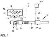
- Figure 1 shows an internal combustion engine 10, which is connected with its outlet 16 to an exhaust system 20.
- the internal combustion engine 10 is preferably designed as a spark-ignited internal combustion engine 10 according to the Otto principle and has a plurality of combustion chambers 12, each of which has at least one spark plug 14 for igniting an ignitable fuel-air mixture.
- the internal combustion engine 10 can also be used as a self-igniting internal combustion engine based on the diesel principle be executed.
- the internal combustion engine 10 is preferably designed as an internal combustion engine 10 charged by means of an exhaust gas turbocharger 18.
- the internal combustion engine 10 can also be designed as a non-supercharged naturally aspirated engine or as an internal combustion engine 10 charged by means of a compressor or an electric compressor.
- the exhaust system 20 comprises an exhaust duct 26, a close-coupled turbine 22 of the exhaust gas turbocharger being arranged in the flow direction of an exhaust gas through the exhaust system 20, a close-coupled catalytic converter 24 downstream of the turbine 22 and a second catalytic converter 28 further downstream, preferably in the underbody position of a motor vehicle.
- At least one of the catalysts is designed as an electrically heatable catalyst 24, 28, preferably as an electrically heatable three-way catalyst or as an electrically heatable four-way catalyst 38.
- the electrically heatable catalytic converter 24, 28 can also be designed as an SCR catalytic converter or as another exhaust gas aftertreatment component.
- At least one of the catalytic converters 24, 28, 38 has an electrical heating element 30, 32, in particular a heating disk, with which the catalytic converter 24, 28, 38 can be heated independently of the exhaust gas flow of the internal combustion engine 10.
- the electrical heating elements 30, 32 are each connected to a control unit 40 of the internal combustion engine 10 via signal lines 34, 36
- the circuit comprises a circuit 44 which connects a battery 42 of the motor vehicle to the electrical heating resistor 48.
- the electrical heating resistor 48 is preferably integrated into the carrier material of the electrically heatable catalytic converter 24, 28, 38 as a metal film or metal wire.
- the circuit has a switch 46, with which the power supply to the heating resistor 48 can be interrupted or activated in a simple manner.
- the battery 42 can be, for example, a 12 volt battery or a 48 volt battery of a motor vehicle with an internal combustion engine. Alternatively, in a hybrid vehicle, the battery 42 can also be the high-voltage battery for the electric drive motor.
- the voltage U R at the heating resistor 48 is preferably sampled by a microcontroller ⁇ C.
- the current intensity I R is preferably measured by shunts or by a current transformer in conjunction with a microcontroller, ⁇ C.
- the switch 46 is designed, for example, as a relay or as a MOSFET.
- the component temperature of the electrically heatable catalytic converter 24, 28, 38 is then a function of the resistance R, which changes as a function of the temperature of the catalytic converter 24, 28, 38.
- the electrical heating resistor 48 can be energized by temporarily switching on the circuit 44 respectively.
- the circuit 44 is opened again by opening the switch 46. Even during operating phases in which the catalytic converter 24, 28, 38 is not to be heated, a resistance measurement can be carried out by briefly energizing the electrical heating resistor 48. The measuring phases are to be made correspondingly short in order to keep the energy input into the heating resistor 48 as low as possible. This prevents overheating of the heating resistor 48 and excessive power consumption.
- An average component temperature is determined by the proposed method.
- the mean component temperature has a metrological basis and is therefore robust against environmental influences which cannot be taken into account when determining the component temperature using a model calculation. Aging effects of the electrical heating resistor 48 can be adapted if the resistance is determined for appropriately aged components and a known ambient temperature.
- a clocked opening and closing of the switch 46 leads to a clocked voltage U and a clocked current intensity I, which can be interpreted as an average voltage or an average current intensity.
- the clocking can be similar to a pulse width modulation clocking as with the down converter or with a lower clock frequency. Such a measurement typically takes place during the switch-on phase of the electrically heatable catalytic converter 24, 28, 38 after the internal combustion engine 10 has been cold-started.
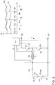
- FIG 3 a preferred embodiment for the electrical circuit 44 for heating the electrically heatable catalytic converter 24, 28, 38 is shown.
- a pulse-width modulation-controlled step-down converter which is preferably designed with MOSFET switches 46, 50, any power input between zero and maximum power can be represented.
- the circuit 44 comprises compared to the in Figure 2
- the illustrated embodiment additionally has a second switch 50 and an inductance, in particular a coil 54.
- the regulation of the current also requires its measurement.
- the current I R and the voltage U R should be measured at least ten times within a pulse width modulation period in order to enable a good averaging.
- the component temperature of the electrically heatable catalytic converter can be determined via the temperature-dependent electrical resistance R of the heating resistor 48, for example, by switching on the switch 46 once for a duration of at least Five times the electrical system time constant or by clocked, multiple switching with a small pulse width modulation ratio.
- FIG 4 is a further development of the in Figure 3 shown measuring arrangement.
- a temperature control 60 for the electrically heatable catalytic converter 24, 28, 38 takes place, the in Figure 3 shown down converter is used as a continuous current regulator 58.
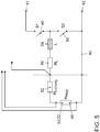
- FIG. 5 a further exemplary embodiment of a circuit 44 for heating the electrically heatable catalytic converter 24, 28, 38 is shown.
- the lines also have an electrical resistance 52, 56, these resistors 52, 56 can also be taken into account.
- the line and contact resistances can be compensated in a suitable form within the scope of the calculation of the electrical resistance R of the heating resistor 48.
- the line resistances are assumed to be constant and subtracted from the measured resistance R. If the measurement accuracy in determining the electrical resistance R of the electrically heatable catalytic converter 24, 28, 38 is to be increased further, what is known as a four-wire measurement, which is shown in FIG Figure 5 is shown. This basically does not change the measurement and control method, but the expected measurement accuracy in the resistance measurement increases. As a result, the deviation in the temperature determination of the component temperature of the electrically heatable catalytic converter 24, 28, 38 can be further reduced.
Landscapes
- Engineering & Computer Science (AREA)
- Chemical & Material Sciences (AREA)
- Chemical Kinetics & Catalysis (AREA)
- Combustion & Propulsion (AREA)
- Mechanical Engineering (AREA)
- General Engineering & Computer Science (AREA)
- Health & Medical Sciences (AREA)
- Toxicology (AREA)
- Physics & Mathematics (AREA)
- General Physics & Mathematics (AREA)
- Power Engineering (AREA)
- Exhaust Gas After Treatment (AREA)
Description
- Die Erfindung betrifft ein Verfahren zur Temperaturermittlung eines elektrisch beheizbaren Katalysators in einer Abgasanlage eines Verbrennungsmotors sowie eine Abgasanlage mit einem solchen elektrisch beheizbaren Katalysator.
- Bei Verbrennungsmotoren erfolgt die Abgasnachbehandlung der Verbrennungsgase durch in der Abgasanlage des Verbrennungsmotors angeordnete Katalysatoren. Da diese Katalysatoren jedoch insbesondere nach einem Kaltstart des Verbrennungsmotors noch nicht ihre zur Konvertierung von Schadstoffen nötige Temperatur erreicht haben, ist die Konvertierung der Schadstoffe in dieser Kaltstartphase unzureichend. Aus dem Stand der Technik sind elektrisch beheizbare Katalysatoren bekannt, bei denen der Katalysator unabhängig vom Abgasstrom durch ein elektrisches Heizelement aufgeheizt werden kann. Somit kann der Zeitraum, in welchem der Katalysator nach einem Kaltstart noch nicht seine zur Konvertierung von Schadstoffen notwendige Temperatur erreicht hat, verkürzt werden. Somit können schädliche Abgaskomponenten nach einem Kaltstart schneller konvertiert und somit die Emissionen eines Kraftfahrzeuges verringert werden.
- Der Betrieb eines elektrisch beheizbaren Katalysators erfordert ein Stellglied für die Stromzufuhr. Als Stellglied kann beispielsweise ein gesteuerter Stromrichter zum Einsatz kommen, welcher über Einrichtungen zur Strom- und Spannungsmessung verfügt.
- Generell ist die Bauteiltemperatur der Katalysatoren in der Abgasanlage eines Kraftfahrzeuges von Interesse, um einerseits die Katalysatorfunktion zu überwachen und andererseits Temperaturgrenzen einzuhalten, ab welchen die Funktion des Katalysators eingeschränkt ist und/oder eine thermische Schädigung des Katalysators droht.
- Grundsätzlich kann die Bauteiltemperatur eines Katalysators durch den Einsatz von Temperatursensoren in der Abgasanlage bestimmt werden. Dies führt allerdings zu einer entsprechenden Kostenerhöhung der Abgasanlage. Daher wird die Bauteiltemperatur in der Regel auf Basis von Modellen ermittelt, welche anhand einer gemessenen oder berechneten Abgastemperatur die Bauteiltemperatur der Katalysatoren in der Abgasanlage berechnen.
- Durch den Einsatz eines elektrisch beheizbaren Katalysators ist es möglich, die Temperatur des Katalysators in der Kaltstartphase zu erhöhen und damit die Umsetzung von schädlichen Abgaskomponenten nach dem Kaltstart zu beschleunigen. Ein solcher elektrisch beheizbarer Katalysator kann sowohl in einer motornahen Position als auch in einer Unterbodenposition eines Kraftfahrzeuges angeordnet sein. Bei der Ermittlung der Bauteiltemperatur aus einem Berechnungsmodell ist aufgrund der Vielzahl von Umgebungseinflüssen mit Unsicherheiten zu rechnen, welche sich mit zunehmendem Abstand des Katalysators vom Auslass des Verbrennungsmotors vergrößern. Daher kann es sein, dass bei einem Katalysator in Unterbodenlage des Kraftfahrzeuges nur eine unzureichende Modellierung der Abgastemperatur möglich ist und die ermittelte Temperatur entsprechend stark von der tatsächlichen Bauteiltemperatur abweicht.
- Aus dem Stand der Technik ist bekannt, bei einem elektrisch beheizbaren Katalysator anhand des Widerstandes des elektrischen Heizelements die Bauteiltemperatur zu ermitteln. Da der Heizwiderstand eines elektrisch beheizbaren Katalysators in der Regel eine hohe Abhängigkeit von der Bauteiltemperatur hat und sich mit zunehmender Bauteiltemperatur bei gleicher Stromstärke erhöht, kann aus dem Heizwiderstand bei bekannter Spannung und bekannter Stromstärke die Bauteiltemperatur des elektrisch beheizbaren Katalysators abgeleitet werden.
- Aus der
DE 8 905 073 U1 ist ein Verfahren zur Ermittlung der Bauteiltemperatur eines elektrisch beheizbaren Katalysators bekannt, welcher aus elektrisch leitenden Schalen aufgebaut ist, wobei die Temperatur durch eine temperaturbedingte Änderung des Widerstandes ermittelt wird. - Aus der
DE 10 2004 046 917 ist bekannt, bei einem elektrisch beheizbaren Katalysator die Temperatur des Katalysators über die Änderung des Widerstandes des elektrischen Heizdrahtes zu ermitteln, wobei das elektrische Beheizen des Katalysators abgeschaltet wird, sobald die auf diese Weise ermittelte Bauteiltemperatur über einer Aktivierungstemperatur (Light-Off-Temperatur) des Katalysators liegt und dieser anschließend dann chemisch durch die katalytische Reaktion weiter aufgeheizt wird. - Die
DE 10 2011 017 675 A1 offenbart ein Verfahren, bei dem die Ermittlung der Temperaturkennlinie eines elektrisch beheizbaren Katalysators aus der temperaturbedingten Veränderung des elektrischen Widerstands eines Heizelements des elektrisch beheizbaren Katalysators erfolgt. - Die
DE 10 2013 008 829 A1 offenbart ein Kraftfahrzeug mit einer Batterie, welche einen ersten Pol und einen zweiten Pol aufweist, sowie mit mindestens einem Kondensator und mindestens einem Verbraucher. Dabei sind ein DC/DC Wandler und eine Steuervorrichtung vorgesehen, wobei der Verbraucher zwischen den ersten Pol der Batterie und ein Erdpotenzial geschaltet ist. Somit fällt an dem Verbraucher eine Betriebsspannung ab, wobei ein Referenzpotential eines Eingangs und eines Ausgangs des DC/DC Wandlers das Erdpotenzial ist. - Aus der
DE 196 45 577 A1 ist eine Abgasreinigungsvorrichtung für einen Verbrennungsmotor bekannt, welche in der Lage ist, einen Katalysator unter Berücksichtigung einer Verschlechterung im Verlauf der Zeit und von Fertigungstoleranzen bei einer elektrischen Heizeinrichtung zur Aufheizung des Katalysators in befriedigender Weise aufzuheizen. - Die
JP 05 001 526 A - Aufgabe der Erfindung ist es, die Ermittlung der Bauteiltemperatur eines elektrisch beheizbaren Katalysators anhand der temperaturbedingten Veränderung des Heizwiderstandes weiter zu verbessern.
- Erfindungsgemäß wird die Aufgabe durch ein Verfahren zur Temperaturermittlung eines elektrisch beheizbaren Katalysators in einer Abgasanlage eines Verbrennungsmotors gelöst. Dabei weist der elektrisch beheizbare Katalysator einen Heizwiderstand mit einem temperaturabhängigen Widerstand auf, wobei die Bauteiltemperatur des elektrisch beheizbaren Katalysators aus dem temperaturabhängigen elektrischen Widerstand des Heizwiderstands ermittelt wird. Es ist vorgesehen, dass die Bestromung des elektrischen Heizwiderstands durch ein Schließen eines Schalters in einem Stromkreis erfolgt, welcher eine Batterie eines Kraftfahrzeuges mit dem elektrischen Heizwiderstand verbindet, wobei die Bauteiltemperatur bei bekannter Stromstärke und bekannter Spannung aus dem elektrischen Widerstand ermittelt wird. Durch ein erfindungsgemäßes Verfahren ist eine Ermittlung der mittleren Bauteiltemperatur des elektrisch beheizbaren Abgaskatalysators, insbesondere eines elektrisch beheizbaren Drei-Wege-Katalysators oder eines elektrisch beheizbaren Vier-Wege-Katalysators, ohne einen zusätzlichen Temperatursensor möglich. Dabei ist der Heizwiderstand vorzugsweise als Heizscheibe ausgebildet, welche mechanisch mit dem Katalysatorkörper des elektrisch beheizbaren Katalysators verbunden ist, um die elektrischen Energie effizient in den Katalysatorkörper einbringen zu können. Die Bauteiltemperatur des elektrisch beheizbaren Katalysators wird dabei auf Basis eines Messwertes ermittelt und ist somit vergleichsweise gering störungsanfällig gegenüber Umwelteinflüssen, welche in einer modellbasierten Bestimmung der Temperatur nicht oder nur unzureichend berücksichtigt werden können. Durch einen schaltbaren Stromkreis ist eine besonders einfache Ansteuerung des elektrischen Heizwiderstandes möglich, sodass der Heizwiderstand jeweils nur kurzzeitig bestromt und somit erhitzt wird, wodurch die Energieeffizienz und die Dauerhaltbarkeit des Heizwiderstands und des elektrisch beheizbaren Katalysators erhöht werden können.
- Durch die in den abhängigen Ansprüchen aufgeführten Merkmale sind vorteilhafte Verbesserungen und Weiterentwicklungen des im unabhängigen Anspruch angegebenen Verfahrens zur Temperaturermittlung der Bauteiltemperatur eines elektrisch beheizbaren Katalysators möglich.
- In bevorzugter Ausgestaltung der Erfindung ist vorgesehen, dass die Bauteiltemperatur des elektrisch beheizbaren Katalysators in einer Betriebsphase ermittelt wird, in welcher ein elektrisches Beheizen des elektrisch beheizbaren Katalysators nicht vorgesehen ist. Durch eine kurzzeitige Ansteuerung des elektrischen Heizwiderstands wird nur eine geringe Energiemenge in den elektrisch beheizbaren Katalysator eingebracht, sodass sich die Temperatur des elektrisch beheizbaren Katalysators während der Messung nur unwesentlich ändern und näherungsweise als konstant angesehen werden kann. Somit kann insbesondere in Betriebszuständen, in denen kein elektrisches Beheizen des Katalysators vorgesehen ist, eine vergleichsweise genaue Ermittlung der Bauteiltemperatur des elektrisch beheizbaren Katalysators erfolgen.
- Bevorzugt ist dabei, wenn die Bestromungsdauer für die Widerstandsmessung in einer solchen Phase zwischen 50 µs und 200 µs gewählt wird. Die Messphase ist entsprechend kurz zu gestalten, um den Energieeintrag in den Heizwiderstand gering zu halten. Dadurch werden eine Überhitzung des Heizelements sowie ein zu hoher Stromverbrauch vermieden. Eine noch kürzere Ansteuerdauer könnte zu Messfehlern führen, da das Messsystem bei kürzerer Messdauer noch nicht seinen eingeschwungenen Zustand erreicht hat. Längere Messphasen führen zu einem unnötig hohen Energieeintrag und einer daraus resultierenden erhöhten Alterung des Heizwiderstandes.
- In einer vorteilhaften Ausführungsform des Verfahrens ist vorgesehen, dass ein Korrekturfaktor ermittelt wird, welcher eine Veränderung des elektrischen Widerstands des Heizwiderstands durch eine Alterung des elektrisch beheizbaren Katalysators berücksichtigt. Durch einen Korrekturfaktur kann eine betriebsbedingte Alterung des elektrischen Widerstands des Heizwiderstands kompensiert und somit die Messgenauigkeit der Bauteiltemperatur über die Lebensdauer des elektrisch beheizbaren Katalysators verbessert werden.
- Erfindungsgemäß ist vorgesehen, dass der Leistungseintrag in den Messstromkreis mittels eines Pulsweitenmodulation gesteuerten Abwärtswandlers erfolgt. Mithilfe eines Pulsweitenmodulation gesteuerten Abwärtswandlers, insbesondere einem Abwärtswandler mit MOSFET Schaltern, besonders bevorzugt mit einer mehrphasig ausgeführten MOSFET Schaltung, lässt sich jeder beliebige Leistungseintrag zwischen Null und Maximalleistung darstellen. Dabei ist der Leistungseintrag durch die Batteriespannung und den elektrischen Widerstand des Heizwiderstands begrenzt.
- Erfindungsgemäß ist dabei vorgesehen, dass die Messung von elektrischer Stromstärke und Spannung mindestens zehnmal innerhalb einer Pulsweitenmodulation-Periode erfolgt. Die Regelung des elektrischen Stroms erfordert auch dessen Messung. Diese Messung von elektrischer Stromstärke I und Spannung U sollte mindestens zehnmal innerhalb einer Pulsweitenmodulation-Periode erfolgen, um eine gute Mittelwertbildung zu ermöglichen. Auch in Phasen, in denen der elektrisch beheizbare Katalysator nicht beheizt wird, kann der elektrische Widerstand des Heizwiderstandes ermittelt und daraus die Bauteiltemperatur berechnet werden. Dies erfolgt entweder durch einmaliges Einschalten des Schalters im Stromkreis oder mehrmaliges Takten bei kleinem Pulsweitenmodulationsverhältnis, bis das System eingeschwungen ist. Bei einem einmaligen Einschalten sollte die Dauer der Bestromung mindestens das Fünffache der elektrischen Systemzeitkonstante betragen, welche sich näherungsweise aus einer Reihenschaltung des Heizwiderstands und einer Induktivität L ergibt.
- Besonders bevorzugt ist dabei, dass eine Temperaturregelung für den elektrisch beheizbaren Katalysator den Abwärtswandler als kontinuierlichen Stromsteller nutzt. Dabei ist eine kontinuierliche Messung von der Stromstärke und der Spannung vorgesehen.
- In einer weiteren Verbesserung des Verfahrens ist vorgesehen, dass bei der Berechnung der Temperatur zusätzlich zum elektrischen Widerstand des Heizwiderstandes der Leitungswiderstand des elektrischen Leiters berücksichtigt wird. Im einfachsten Fall wird der Leitungswiderstand als konstant angesehen und vom gemessenen Widerstand des Heizwiderstands abgezogen.
- In weiterer bevorzugter Ausgestaltung der Erfindung ist vorgesehen, dass die Widerstandsmessung mittels einer Vierdraht-Messmethode erfolgt. Soll die Messgenauigkeit bei der Bestimmung des elektrischen Widerstands des Heizwiderstands weiter erhöht werden, bietet sich eine sogenannte Vierdraht-Messmethode an. Das Mess- und Ansteuerverfahren wird dadurch nicht grundsätzlich verändert, jedoch kann die Messgenauigkeit verbessert werden.
- Erfindungsgemäß wird ein Abgasnachbehandlungssystem für einen Verbrennungsmotor mit einer Abgasanlage vorgeschlagen, in welcher ein elektrisch beheizbarer Katalysator, insbesondere ein elektrisch beheizbarer Drei-Wege-Katalysator oder ein elektrisch beheizbarer Vier-Wege-Katalysator, angeordnet ist. Das Abgasnachbehandlungssystem umfasst ein Steuergerät, insbesondere ein Motorsteuergerät des Verbrennungsmotors, welches dazu eingerichtet ist, ein erfindungsgemäßes Verfahren durchzuführen, wenn ein maschinenlesbarer Programmcode durch das Steuergerät ausgeführt wird. In einem erfindungsgemäßen Abgasnachbehandlungssystem ist es möglich, die Bauteiltemperatur des elektrisch beheizbaren Katalysators vergleichsweise energiesparend und genau zu ermitteln, sodass der Katalysator mit hoher Effizienz betrieben werden kann. Somit kann die Konvertierungsleistung des Katalysators erhöht und/oder das Alterungsverhalten des Katalysators verbessert werden.
- Weitere bevorzugte Ausgestaltungen der Erfindung ergeben sich aus den übrigen, in den Unteransprüchen genannten Merkmalen.
- Die verschiedenen in dieser Anmeldung genannten Ausführungsformen der Erfindung sind, sofern im Einzelfall nicht anders ausgeführt, mit Vorteil miteinander kombinierbar.
- Die Erfindung wird nachfolgend in Ausführungsbeispielen anhand der zugehörigen Zeichnungen erläutert. Es zeigen:
- Figur 1
- einen Verbrennungsmotor mit einer Abgasanlage, in der ein elektrisch beheizbarer Katalysator zur Abgasnachbehandlung der Verbrennungsgase des Verbrennungsmotors angeordnet ist;
- Figur 2
- einen elektrischen Schaltkreis zur Ansteuerung eines elektrischen Heizwiderstands zum elektrischen Beheizen eines Katalysators;
- Figur 3
- einen weiteren elektrischen Schaltkreis zur Ansteuerung eines elektrischen Heizwiderstands eines elektrisch beheizbaren Katalysators
- Figur 4
- eine Regleranordnung zur Temperatur- und Stromregelung für den elektrischen Heizwiderstand des elektrisch beheizbaren Katalysators, und
- Figur 5
- einen weiteren elektrischen Schaltkreis zur Ansteuerung eines elektrischen Heizwiderstands eines elektrisch beheizbaren Katalysators.
-
Figur 1 zeigt einen Verbrennungsmotor 10, welcher mit seinem Auslass 16 mit einer Abgasanlage 20 verbunden ist. Der Verbrennungsmotor 10 ist vorzugsweise als fremdgezündeter Verbrennungsmotor 10 nach dem Ottoprinzip ausgeführt und weist eine Mehrzahl von Brennräumen 12 auf, an welche jeweils mindestens eine Zündkerze 14 zur Zündung eines zündfähigen Kraftstoff-Luft-Gemischs angeordnet ist. Alternativ kann der Verbrennungsmotor 10 auch als selbstzündender Verbrennungsmotor nach dem Dieselprinzip ausgeführt sein. Der Verbrennungsmotor 10 ist vorzugsweise als mittels eines Abgasturboladers 18 aufgeladenen Verbrennungsmotor 10 ausgeführt. Alternativ kann der Verbrennungsmotor 10 auch als nicht aufgeladener Saugmotor oder als mittels eines Kompressors oder elektrischen Verdichters aufgeladener Verbrennungsmotor 10 ausgeführt sein. Die Abgasanlage 20 umfasst einen Abgaskanal 26, wobei in Strömungsrichtung eines Abgases durch die Abgasanlage 20 eine motornahe Turbine 22 des Abgasturboladers, stromabwärts der Turbine 22 ein motornaher Katalysator 24 und weiter stromabwärts, vorzugsweise in Unterbodenlage eines Kraftfahrzeuges, ein zweiter Katalysator 28 angeordnet sind. Zumindest einer der Katalysatoren ist als elektrisch beheizbarer Katalysator 24, 28, vorzugsweise als elektrisch beheizbarer Drei-Wege-Katalysator oder als elektrisch beheizbarer Vier-Wege-Katalysator 38 ausgeführt. Alternativ kann der elektrisch beheizbare Katalysator 24, 28 auch als SCR-Katalysator oder als sonstige Abgasnachbehandlungskomponente ausgeführt sein. Mindestens einer der Katalysatoren 24, 28, 38 weist ein elektrisches Heizelement 30, 32, insbesondere eine Heizscheibe auf, mit welcher der Katalysator 24, 28, 38 unabhängig vom Abgasstrom des Verbrennungsmotors 10 beheizt werden kann. Dazu sind die elektrischen Heizelemente 30, 32 jeweils über Signalleitungen 34, 36 mit einem Steuergerät 40 des Verbrennungsmotors 10 verbunden - In
Figur 2 ist ein elektrischer Schaltkreis für das elektrische Heizelement 30, 32, insbesondere für einen Heizwiderstand 48 dargestellt. Dabei umfasst der Schaltkreis einen Stromkreis 44, welcher eine Batterie 42 des Kraftfahrzeuges mit dem elektrischen Heizwiderstand 48 verbindet. Der elektrische Heizwiderstand 48 ist vorzugsweise als Metallfilm oder Metalldraht in das Trägermaterial des elektrisch beheizbaren Katalysators 24, 28, 38 integriert. Ferner weist der Schaltkreis einen Schalter 46 auf, mit welchem auf einfache Art und Weise die Stromzufuhr zu dem Heizwiderstand 48 unterbrochen beziehungsweise aktiviert werden kann. Die Batterie 42 kann beispielsweise eine 12 Volt Batterie oder eine 48 Volt Batterie eines Kraftfahrzeugs mit Verbrennungsmotor sein. Alternativ kann die Batterie 42 bei einem Hybridfahrzeug auch die Hochvoltbatterie für den elektrischen Antriebsmotor sein. Die Spannung UR am Heizwiderstand 48 wird vorzugsweise durch einen Mikrocontroller µC abgetastet. Die Stromstärke IR wird vorzugsweise durch Shunts oder durch einen Stromwandler in Verbindung mit einem Mikrocontroller µC gemessen. Der Schalter 46 ist beispielsweise als Relais oder als MOSFET ausgebildet. Der Heizwiderstand R ergibt sich aus der Spannung UR und der Stromstärke IR durch die Beziehung R = UR / IR. Die Bauteiltemperatur des elektrisch beheizbaren Katalysators 24, 28, 38 ist dann eine Funktion des Widerstands R, welcher sich in Abhängigkeit von der Temperatur des Katalysators 24, 28, 38 ändert. Das Bestromen des elektrischen Heizwiderstands 48 kann im einfachsten Fall durch zeitweises Einschalten des Stromkreises 44 erfolgen. Ist die gewünschte Bauteiltemperatur des elektrisch beheizbaren Katalysators 24, 28, 38 erreicht oder eine gewisse Zeitspanne verstrichen, wird der Stromkreis 44 durch Öffnen des Schalters 46 wieder geöffnet. Auch während Betriebsphasen, in denen der Katalysator 24, 28, 38 nicht beheizt werden soll, kann durch kurzzeitiges Bestromen des elektrischen Heizwiderstands 48 eine Widerstandsmessung erfolgen. Die Messphasen sind entsprechend kurz zu gestalten, um den Energieeintrag in den Heizwiderstand 48 möglichst gering zu halten. Dadurch wird eine Überhitzung des Heizwiderstands 48 sowie ein zu hoher Stromverbrauch vermieden. - Durch das vorgeschlagene Verfahren wird eine mittlere Bauteiltemperatur bestimmt. Die mittlere Bauteiltemperatur hat eine messtechnische Basis und ist damit robust gegenüber Umwelteinflüssen, welche in einer Ermittlung der Bauteiltemperatur über eine Modellberechnung nicht berücksichtigt werden können. Alterungseffekte des elektrischen Heizwiderstands 48 können adaptiert werden, wenn der Widerstand bei entsprechend gealterten Bauteilen und bekannter Umgebungstemperatur bestimmt wird.
- Ein getaktetes Öffnen und Schließen des Schalters 46 führt zu einer getakteten Spannung U und einer getakteten Stromstärke I, die sich als mittlere Spannung beziehungsweise mittlere Stromstärke interpretieren lassen. Die Taktung kann ähnlich einer Pulsweitenmodulations-Taktung wie beim Abwärtswandler erfolgen oder mit geringerer Taktfrequenz. Typischerweise erfolgt eine solche Messung während der Einschaltphase des elektrisch beheizbaren Katalysators 24, 28, 38 nach dem Kaltstart des Verbrennungsmotors 10.
- In
Figur 3 ist ein bevorzugtes Ausführungsbeispiel für den elektrischen Stromkreis 44 zum Beheizen des elektrisch beheizbaren Katalysators 24, 28, 38 dargestellt. Mithilfe eines Pulsweitenmodulation gesteuerten Abwärtswandlers, welcher vorzugsweise mit MOSFET-Schaltern 46, 50 ausgeführt ist, lässt sich jeder beliebige Leistungseintrag zwischen Null und Maximalleistung darstellen. Der Stromkreis 44 umfasst gegenüber dem inFigur 2 dargestellten Ausführungsbeispiel zusätzlich einen zweiten Schalter 50 und eine Induktivität, insbesondere eine Spule 54. Die Regelung des Stroms erfordert auch dessen Messung. Die Messung der Stromstärke IR und der Spannung UR sollte mindestens zehnmal innerhalb einer Pulsweitenmodulations-Periode erfolgen, um eine gute Mittelwertbildung zu ermöglichen. Die Ermittlung der Bauteiltemperatur des elektrisch beheizbaren Katalysators über den temperaturabhängigen elektrischen Widerstand R des Heizwiderstands 48 kann beispielsweise durch einmaliges Einschalten des Schalters 46 mit einer Dauer von mindestens dem Fünffachen der elektrischen Systemzeitkonstante oder durch getaktetes, mehrmaliges Schalten bei kleinem Pulsweitenmodulationsverhältnis erfolgen. - In
Figur 4 ist eine Weiterentwicklung der inFigur 3 dargestellten Messanordnung gezeigt. Dabei erfolgt eine Temperaturregelung 60 für den elektrisch beheizbaren Katalysator 24, 28, 38, wobei der inFigur 3 dargestellte Abwärtswandler als kontinuierlicher Stromregler 58 genutzt wird. - In
Figur 5 ist ein weiteres Ausführungsbeispiel für einen Stromkreis 44 zum Beheizen des elektrisch beheizbaren Katalysators 24, 28, 38 dargestellt. Da im realen Betrieb neben dem elektrischen Widerstand R des Heizwiderstands 48 auch die Leitungen einen elektrischen Widerstand 52, 56 aufweisen, können auch diese Widerstände 52, 56 berücksichtigt werden. Die Leitungs- und Übergangswiderstände können im Rahmen der Berechnung des elektrischen Widerstands R des Heizwiderstands 48 in geeigneter Form kompensiert werden. In der einfachsten Form werden die Leitungswiderstände als konstant angenommen und vom gemessenen Widerstand R abgezogen. Soll die Messgenauigkeit bei der Bestimmung des elektrischen Widerstands R des elektrisch beheizbaren Katalysators 24, 28, 38 weiter erhöht werden, bietet sich eine sogenannte Vierdraht-Messung an, welche inFigur 5 dargestellt ist. Das Mess- und Ansteuerverfahren wird dadurch grundsätzlich nicht verändert, jedoch erhöht sich die zu erwartende Messgenauigkeit bei der Widerstandsmessung. Dadurch kann auch die Abweichung bei der Temperaturbestimmung der Bauteiltemperatur des elektrisch beheizbaren Katalysators 24, 28, 38 weiter verringert werden. -
- 10
- Verbrennungsmotor
- 12
- Brennraum
- 14
- Zündkerze
- 16
- Auslass
- 18
- Abgasturbolader
- 20
- Abgasanlage
- 22
- Turbine
- 24
- motornaher Katalysator
- 26
- Abgaskanal
- 28
- zweiter Katalysator
- 30
- erstes Heizelement
- 32
- zweites Heizelement
- 34
- Signalleitung
- 36
- Signalleitung
- 38
- Vier-Wege-Katalysator
- 40
- Steuergerät
- 42
- Batterie
- 44
- Stromkreis
- 46
- erster Schalter
- 48
- Heizwiderstand
- 50
- zweiter Schalter
- 52
- Leitungswiderstand
- 54
- Spule
- 56
- zweiter Leitungswiderstand
- 58
- Stromregler
- 60
- Temperaturregler
- I
- Stromstärke
- L
- Spule
- R
- Widerstand
- S
- Schalter
- U
- Spannung
- t
- Zeit
Claims (8)
- Verfahren zur Temperaturermittlung eines elektrisch beheizbaren Katalysators (24, 28) in einer Abgasanlage (20) eines Verbrennungsmotors (10), wobei der elektrisch beheizbare Katalysator (24, 28) einen Heizwiderstand (48) mit einem temperaturabhängigen Widerstand aufweist, und wobei die Bauteiltemperatur des elektrisch beheizbaren Katalysators (24, 28) aus dem temperaturabhängigen Widerstand des Heizwiderstands (48) ermittelt wird, wobei die Bestromung des elektrischen Heizwiderstands (48) durch ein Schließen eines Schalters (46, 50) in einem Stromkreis (44) erfolgt, welcher eine Batterie (42) mit dem elektrischen Heizwiderstand (48) verbindet, wobei die Bauteiltemperatur bei bekannter Stromstärke (I) und bekannter Spannung (U) aus dem elektrischen Widerstand (R) ermittelt wird, dadurch gekennzeichnet, dass der Leistungseintrag in den Messstromkreis mittels eines Pulsweitenmodulation-gesteuerten Abwärtswandlers erfolgt, wobei die Messung von Stromstärke (I) und Spannung (U) mindestens zehnmal innerhalb einer Pulsweitenmodulations-Periode erfolgt.
- Verfahren nach Anspruch 1, dadurch gekennzeichnet, dass die Bauteiltemperatur des elektrisch beheizbaren Katalysators (24, 28) in einer Betriebsphase ermittelt wird, in der elektrisches Beheizen nicht vorgesehen ist.
- Verfahren nach Anspruch 2, dadurch gekennzeichnet, dass die Bestromungsdauer für die Widerstandsmessung zwischen 50 und 200 µs gewählt wird.
- Verfahren nach einem der Ansprüche 1 bis 3, dadurch gekennzeichnet, dass ein Korrekturfaktor ermittelt wird, welcher eine Veränderung des elektrischen Widerstands (R) des Heizwiderstands (48) durch eine Alterung des elektrisch beheizbaren Katalysators (24, 28) berücksichtigt.
- Verfahren nach einem der Ansprüche 1 bis 4, dadurch gekennzeichnet, dass eine Temperaturregelung für den elektrisch beheizbaren Katalysator (24, 28) den Abwärtswandler als kontinuierlichen Stromsteller nutzt.
- Verfahren nach einem der Ansprüche 1 bis 5, dadurch gekennzeichnet, dass bei der Berechnung der Temperatur zusätzlich zu dem elektrischen Widerstand (R) des Heizwiderstands (48) der Leitungswiderstand (52, 56) des elektrischen Leiters berücksichtigt wird.
- Verfahren nach einem der Ansprüche 1 bis 6, dadurch gekennzeichnet, dass die Widerstandsmessung mittels einer Vierdraht-Messmethode erfolgt.
- Abgasnachbehandlungssystem für einen Verbrennungsmotor (10) mit einer Abgasanlage (20), in welcher ein elektrisch beheizbaren Katalysator (24, 28) angeordnet ist, sowie mit einem Steuergerät (40), welches dazu eingerichtet ist, ein Verfahren nach einem der Ansprüche 1 bis 7 durchzuführen, wenn ein maschinenlesbarer Programmcode durch das Steuergerät (40) ausgeführt wird.
Applications Claiming Priority (1)
| Application Number | Priority Date | Filing Date | Title |
|---|---|---|---|
| DE102018110382.4A DE102018110382A1 (de) | 2018-04-30 | 2018-04-30 | Verfahren zur Temperaturermittlung eines elektrisch beheizbaren Katalysators |
Publications (2)
| Publication Number | Publication Date |
|---|---|
| EP3564503A1 EP3564503A1 (de) | 2019-11-06 |
| EP3564503B1 true EP3564503B1 (de) | 2020-12-09 |
Family
ID=66102510
Family Applications (1)
| Application Number | Title | Priority Date | Filing Date |
|---|---|---|---|
| EP19167837.4A Active EP3564503B1 (de) | 2018-04-30 | 2019-04-08 | Verfahren zur temperaturermittlung eines elektrisch beheizbaren katalysators |
Country Status (4)
| Country | Link |
|---|---|
| US (1) | US10731533B2 (de) |
| EP (1) | EP3564503B1 (de) |
| CN (1) | CN110410188B (de) |
| DE (1) | DE102018110382A1 (de) |
Families Citing this family (12)
| Publication number | Priority date | Publication date | Assignee | Title |
|---|---|---|---|---|
| DE102019204992A1 (de) * | 2019-04-08 | 2020-10-08 | Vitesco Technologies GmbH | Verfahren und Vorrichtung zum Überprüfen und Sicherstellen einer Funktionsfähigkeit eines Abgasnachbehandlungssystems einer Brennkraftmaschine |
| DE102020119057B3 (de) * | 2020-07-20 | 2021-08-26 | Dr. Ing. H.C. F. Porsche Aktiengesellschaft | Abgastrakt für eine Verbrennungskraftmaschine |
| DE102021204013B4 (de) * | 2021-04-22 | 2023-03-09 | Vitesco Technologies GmbH | Verfahren und Steuervorrichtung zum Detektieren einer Fehlfunktion eines elektrisch beheizten Katalysatorsystems |
| DE102021113989A1 (de) * | 2021-05-31 | 2022-12-01 | Purem GmbH | Abgasheizer |
| EP4119778A1 (de) * | 2021-07-12 | 2023-01-18 | Vitesco Technologies GmbH | Verfahren zur überwachung der funktion eines elektrisch erwärmbaren katalysators |
| KR20230020286A (ko) * | 2021-08-03 | 2023-02-10 | 현대자동차주식회사 | 하이브리드차량의 파워트레인의 제어방법 |
| CN113639886A (zh) * | 2021-09-08 | 2021-11-12 | 中国兵器装备集团自动化研究所有限公司 | 一种发热丝温度离线测量方法及系统 |
| CN113750786B (zh) * | 2021-09-17 | 2022-08-30 | 宁波久丰热电有限公司 | 一种基于静电场耦合烟气脱硝的scr反应系统 |
| DE102021214459A1 (de) * | 2021-12-15 | 2023-06-15 | Vitesco Technologies GmbH | Verfahren und Vorrichtung zur Überprüfung der Funktion einer elektrischen Heizeinrichtung eines Abgaskatalysators im Abgassystem einer Brennkraftmaschine |
| DE102022205330A1 (de) | 2022-05-30 | 2023-11-30 | Psa Automobiles Sa | Verfahren zur Temperaturermittlung eines elektrisch beheizbaren Katalysators einer Abgasanlage eines Verbrennungsmotors eines Fahrzeugs |
| DE102022206580A1 (de) * | 2022-06-29 | 2024-01-04 | Vitesco Technologies GmbH | Verfahren zum Betreiben eines elektrisch beheizbaren Katalysators und elektrisch beheizbarer Katalysator |
| US11885250B1 (en) * | 2023-05-10 | 2024-01-30 | GM Global Technology Operations LLC | Vehicle systems and methods for aftertreatment preheating |
Family Cites Families (14)
| Publication number | Priority date | Publication date | Assignee | Title |
|---|---|---|---|---|
| DE8905073U1 (de) | 1989-04-21 | 1990-08-30 | Emitec Gesellschaft für Emissionstechnologie mbH, 5204 Lohmar | Elektrisch leitfähiger Wabenkörper |
| JPH051526A (ja) | 1991-06-25 | 1993-01-08 | Nippondenso Co Ltd | 金属担体触媒の制御装置 |
| JP3322098B2 (ja) | 1995-11-06 | 2002-09-09 | トヨタ自動車株式会社 | 内燃機関の排気浄化装置 |
| US7952335B2 (en) * | 2004-08-09 | 2011-05-31 | St-Ericsson Sa | Power converter and method for power conversion |
| DE102004046917A1 (de) * | 2004-09-28 | 2006-03-30 | Daimlerchrysler Ag | Verfahren zum Betrieb einer Vorrichtung zur katalytischen Umwandlung unerwünschter Bestandteile von Abgasen |
| CN2938552Y (zh) * | 2006-04-14 | 2007-08-22 | 崇贸科技股份有限公司 | 功率转换器的控制电路 |
| JP4656077B2 (ja) * | 2007-03-22 | 2011-03-23 | カシオ計算機株式会社 | 温度制御装置及び温度制御方法 |
| US8014930B2 (en) * | 2008-10-30 | 2011-09-06 | GM Global Technology Operations LLC | System and method for determining oxygen sensor heater resistance |
| DE102010001090A1 (de) * | 2010-01-21 | 2011-07-28 | Robert Bosch GmbH, 70469 | Verfahren zum Betreiben einer Brennkraftmaschine sowie entsprechende Vorrichtung |
| JP5056895B2 (ja) * | 2010-04-28 | 2012-10-24 | 株式会社デンソー | 触媒温度算出装置 |
| GB2512040A (en) * | 2012-12-31 | 2014-09-24 | Continental Automotive Systems | Using resistance equivalent to estimate heater temperature of an exhaust gas after-treatment component |
| DE102013008829B4 (de) * | 2013-05-24 | 2017-01-12 | Audi Ag | Kraftfahrzeug |
| WO2017218791A1 (en) * | 2016-06-15 | 2017-12-21 | Watlow Electric Manufacturing Company | Power converter for a thermal system |
| GB2561178A (en) * | 2017-04-03 | 2018-10-10 | Ford Global Tech Llc | Improvements in or relating to oil sensors |
-
2018
- 2018-04-30 DE DE102018110382.4A patent/DE102018110382A1/de not_active Withdrawn
-
2019
- 2019-03-29 US US16/370,300 patent/US10731533B2/en active Active
- 2019-04-08 EP EP19167837.4A patent/EP3564503B1/de active Active
- 2019-04-23 CN CN201910328045.4A patent/CN110410188B/zh active Active
Also Published As
| Publication number | Publication date |
|---|---|
| CN110410188B (zh) | 2022-03-22 |
| EP3564503A1 (de) | 2019-11-06 |
| US20190331015A1 (en) | 2019-10-31 |
| DE102018110382A1 (de) | 2019-10-31 |
| US10731533B2 (en) | 2020-08-04 |
| CN110410188A (zh) | 2019-11-05 |
Similar Documents
| Publication | Publication Date | Title |
|---|---|---|
| EP3564503B1 (de) | Verfahren zur temperaturermittlung eines elektrisch beheizbaren katalysators | |
| EP2066883B1 (de) | Verfahren zum betreiben eines reagenzmittel-dosierventils und vorrichtung zur durchführung des verfahrens | |
| EP3551857B1 (de) | Verfahren zum betrieb eines elektrisch beheizbaren katalysators | |
| DE10001992A1 (de) | Verfahren zur temporären Erhöhung einer Abgastemperatur einer Verbrennungskraftmaschine | |
| EP2379931A1 (de) | Elektrisches heizsystem für ein fluid-leitungssystem | |
| DE102016122304A1 (de) | Verfahren zum Aufheizen eines Katalysators sowie Kraftfahrzeug mit einem Katalysator | |
| DE102014001418A1 (de) | Verfahren zur Temperatureinstellung einer Abgasnachbehandlungseinrichtung | |
| EP3608519B1 (de) | Verfahren und vorrichtung zur abgasnachbehandlung eines verbrennungsmotors | |
| DE102010001004A1 (de) | Verfahren und Vorrichtung zur Ansteuerung von Aktuatoren | |
| DE102013226901A1 (de) | Widerstandsbestimmung zur Temperatursteuerung erwärmter Fahrzeugkomponenten | |
| DE102010042271A1 (de) | Verfahren und Vorrichtung für ein Temperaturmanagement einer Abgasreinigungsanlage | |
| DE102013209070A1 (de) | Verfahren und Vorrichtung zur Erkennung eines Bewegungsbeginns von elektromechanischen Aktuatoren | |
| DE102012216611A1 (de) | Verfahren zum Betreiben eines Magnetventils | |
| DE10201465B4 (de) | Verfahren und Vorrichtung zum Steuern einer Bauteilschutzfunktion | |
| DE102008030307A1 (de) | Katalysatoranordnung zur Reinigung eines Abgasstroms eines Verbrennungsmotors | |
| DE2608606C2 (de) | ||
| DE102017107678A1 (de) | Verfahren zur Inbetriebnahme eines Verbrennungsmotors und Kraftfahrzeug mit einem Verbrennungsmotor | |
| DE102011089996B4 (de) | Bordnetzsystem und Verfahren zum Betreiben eines Bordnetzsystems | |
| DE102009012094A1 (de) | Verfahren zum Betrieb einer Vorrichtung zur Reinigung von Abgas mit einem Heizapparat | |
| DE69716519T2 (de) | Verfahren und Vorrichtung zur Steuerung der Stromversorgung eines Heizers in einer Sauerstoffmesssonde | |
| DE19940802B4 (de) | Anordnung zum elektrischen Beheizen eines Katalysators | |
| WO2020182705A1 (de) | Abgasnachbehandlungsvorrichtung und verfahren zum betrieb der vorrichtung | |
| DE102014015486A1 (de) | Betriebsarten- und kennfeldabhängig umschaltbare Funkenbandzündung | |
| DE102014205919A1 (de) | Verfahren zum Betreiben eines elektromagnetisch betriebenen Schaltantriebs, Vorrichtung zur Durchführung des Verfahrens, Computerprogramm sowie Computerprogrammprodukt | |
| EP1517011A2 (de) | Abgasanlage mit Partikelfilter sowie zugehörige Heizeinrichtung und zugehöriges Regenerationsverfahren |
Legal Events
| Date | Code | Title | Description |
|---|---|---|---|
| PUAI | Public reference made under article 153(3) epc to a published international application that has entered the european phase |
Free format text: ORIGINAL CODE: 0009012 |
|
| STAA | Information on the status of an ep patent application or granted ep patent |
Free format text: STATUS: THE APPLICATION HAS BEEN PUBLISHED |
|
| AK | Designated contracting states |
Kind code of ref document: A1 Designated state(s): AL AT BE BG CH CY CZ DE DK EE ES FI FR GB GR HR HU IE IS IT LI LT LU LV MC MK MT NL NO PL PT RO RS SE SI SK SM TR |
|
| AX | Request for extension of the european patent |
Extension state: BA ME |
|
| STAA | Information on the status of an ep patent application or granted ep patent |
Free format text: STATUS: REQUEST FOR EXAMINATION WAS MADE |
|
| 17P | Request for examination filed |
Effective date: 20200506 |
|
| RBV | Designated contracting states (corrected) |
Designated state(s): AL AT BE BG CH CY CZ DE DK EE ES FI FR GB GR HR HU IE IS IT LI LT LU LV MC MK MT NL NO PL PT RO RS SE SI SK SM TR |
|
| RIC1 | Information provided on ipc code assigned before grant |
Ipc: F01N 3/20 20060101AFI20200519BHEP Ipc: F01N 9/00 20060101ALI20200519BHEP |
|
| GRAP | Despatch of communication of intention to grant a patent |
Free format text: ORIGINAL CODE: EPIDOSNIGR1 |
|
| STAA | Information on the status of an ep patent application or granted ep patent |
Free format text: STATUS: GRANT OF PATENT IS INTENDED |
|
| INTG | Intention to grant announced |
Effective date: 20200703 |
|
| GRAS | Grant fee paid |
Free format text: ORIGINAL CODE: EPIDOSNIGR3 |
|
| GRAA | (expected) grant |
Free format text: ORIGINAL CODE: 0009210 |
|
| STAA | Information on the status of an ep patent application or granted ep patent |
Free format text: STATUS: THE PATENT HAS BEEN GRANTED |
|
| AK | Designated contracting states |
Kind code of ref document: B1 Designated state(s): AL AT BE BG CH CY CZ DE DK EE ES FI FR GB GR HR HU IE IS IT LI LT LU LV MC MK MT NL NO PL PT RO RS SE SI SK SM TR |
|
| REG | Reference to a national code |
Ref country code: GB Ref legal event code: FG4D Free format text: NOT ENGLISH |
|
| REG | Reference to a national code |
Ref country code: CH Ref legal event code: EP Ref country code: AT Ref legal event code: REF Ref document number: 1343674 Country of ref document: AT Kind code of ref document: T Effective date: 20201215 |
|
| REG | Reference to a national code |
Ref country code: DE Ref legal event code: R096 Ref document number: 502019000497 Country of ref document: DE |
|
| REG | Reference to a national code |
Ref country code: IE Ref legal event code: FG4D Free format text: LANGUAGE OF EP DOCUMENT: GERMAN |
|
| PG25 | Lapsed in a contracting state [announced via postgrant information from national office to epo] |
Ref country code: FI Free format text: LAPSE BECAUSE OF FAILURE TO SUBMIT A TRANSLATION OF THE DESCRIPTION OR TO PAY THE FEE WITHIN THE PRESCRIBED TIME-LIMIT Effective date: 20201209 Ref country code: RS Free format text: LAPSE BECAUSE OF FAILURE TO SUBMIT A TRANSLATION OF THE DESCRIPTION OR TO PAY THE FEE WITHIN THE PRESCRIBED TIME-LIMIT Effective date: 20201209 Ref country code: NO Free format text: LAPSE BECAUSE OF FAILURE TO SUBMIT A TRANSLATION OF THE DESCRIPTION OR TO PAY THE FEE WITHIN THE PRESCRIBED TIME-LIMIT Effective date: 20210309 Ref country code: GR Free format text: LAPSE BECAUSE OF FAILURE TO SUBMIT A TRANSLATION OF THE DESCRIPTION OR TO PAY THE FEE WITHIN THE PRESCRIBED TIME-LIMIT Effective date: 20210310 |
|
| PG25 | Lapsed in a contracting state [announced via postgrant information from national office to epo] |
Ref country code: SE Free format text: LAPSE BECAUSE OF FAILURE TO SUBMIT A TRANSLATION OF THE DESCRIPTION OR TO PAY THE FEE WITHIN THE PRESCRIBED TIME-LIMIT Effective date: 20201209 Ref country code: LV Free format text: LAPSE BECAUSE OF FAILURE TO SUBMIT A TRANSLATION OF THE DESCRIPTION OR TO PAY THE FEE WITHIN THE PRESCRIBED TIME-LIMIT Effective date: 20201209 Ref country code: BG Free format text: LAPSE BECAUSE OF FAILURE TO SUBMIT A TRANSLATION OF THE DESCRIPTION OR TO PAY THE FEE WITHIN THE PRESCRIBED TIME-LIMIT Effective date: 20210309 |
|
| REG | Reference to a national code |
Ref country code: NL Ref legal event code: MP Effective date: 20201209 |
|
| PG25 | Lapsed in a contracting state [announced via postgrant information from national office to epo] |
Ref country code: HR Free format text: LAPSE BECAUSE OF FAILURE TO SUBMIT A TRANSLATION OF THE DESCRIPTION OR TO PAY THE FEE WITHIN THE PRESCRIBED TIME-LIMIT Effective date: 20201209 Ref country code: NL Free format text: LAPSE BECAUSE OF FAILURE TO SUBMIT A TRANSLATION OF THE DESCRIPTION OR TO PAY THE FEE WITHIN THE PRESCRIBED TIME-LIMIT Effective date: 20201209 |
|
| REG | Reference to a national code |
Ref country code: LT Ref legal event code: MG9D |
|
| PG25 | Lapsed in a contracting state [announced via postgrant information from national office to epo] |
Ref country code: CZ Free format text: LAPSE BECAUSE OF FAILURE TO SUBMIT A TRANSLATION OF THE DESCRIPTION OR TO PAY THE FEE WITHIN THE PRESCRIBED TIME-LIMIT Effective date: 20201209 Ref country code: EE Free format text: LAPSE BECAUSE OF FAILURE TO SUBMIT A TRANSLATION OF THE DESCRIPTION OR TO PAY THE FEE WITHIN THE PRESCRIBED TIME-LIMIT Effective date: 20201209 Ref country code: SK Free format text: LAPSE BECAUSE OF FAILURE TO SUBMIT A TRANSLATION OF THE DESCRIPTION OR TO PAY THE FEE WITHIN THE PRESCRIBED TIME-LIMIT Effective date: 20201209 Ref country code: SM Free format text: LAPSE BECAUSE OF FAILURE TO SUBMIT A TRANSLATION OF THE DESCRIPTION OR TO PAY THE FEE WITHIN THE PRESCRIBED TIME-LIMIT Effective date: 20201209 Ref country code: LT Free format text: LAPSE BECAUSE OF FAILURE TO SUBMIT A TRANSLATION OF THE DESCRIPTION OR TO PAY THE FEE WITHIN THE PRESCRIBED TIME-LIMIT Effective date: 20201209 Ref country code: RO Free format text: LAPSE BECAUSE OF FAILURE TO SUBMIT A TRANSLATION OF THE DESCRIPTION OR TO PAY THE FEE WITHIN THE PRESCRIBED TIME-LIMIT Effective date: 20201209 Ref country code: PT Free format text: LAPSE BECAUSE OF FAILURE TO SUBMIT A TRANSLATION OF THE DESCRIPTION OR TO PAY THE FEE WITHIN THE PRESCRIBED TIME-LIMIT Effective date: 20210409 |
|
| PG25 | Lapsed in a contracting state [announced via postgrant information from national office to epo] |
Ref country code: PL Free format text: LAPSE BECAUSE OF FAILURE TO SUBMIT A TRANSLATION OF THE DESCRIPTION OR TO PAY THE FEE WITHIN THE PRESCRIBED TIME-LIMIT Effective date: 20201209 |
|
| REG | Reference to a national code |
Ref country code: DE Ref legal event code: R097 Ref document number: 502019000497 Country of ref document: DE |
|
| PG25 | Lapsed in a contracting state [announced via postgrant information from national office to epo] |
Ref country code: IS Free format text: LAPSE BECAUSE OF FAILURE TO SUBMIT A TRANSLATION OF THE DESCRIPTION OR TO PAY THE FEE WITHIN THE PRESCRIBED TIME-LIMIT Effective date: 20210409 |
|
| PLBE | No opposition filed within time limit |
Free format text: ORIGINAL CODE: 0009261 |
|
| STAA | Information on the status of an ep patent application or granted ep patent |
Free format text: STATUS: NO OPPOSITION FILED WITHIN TIME LIMIT |
|
| PG25 | Lapsed in a contracting state [announced via postgrant information from national office to epo] |
Ref country code: AL Free format text: LAPSE BECAUSE OF FAILURE TO SUBMIT A TRANSLATION OF THE DESCRIPTION OR TO PAY THE FEE WITHIN THE PRESCRIBED TIME-LIMIT Effective date: 20201209 Ref country code: IT Free format text: LAPSE BECAUSE OF FAILURE TO SUBMIT A TRANSLATION OF THE DESCRIPTION OR TO PAY THE FEE WITHIN THE PRESCRIBED TIME-LIMIT Effective date: 20201209 |
|
| 26N | No opposition filed |
Effective date: 20210910 |
|
| PG25 | Lapsed in a contracting state [announced via postgrant information from national office to epo] |
Ref country code: MC Free format text: LAPSE BECAUSE OF FAILURE TO SUBMIT A TRANSLATION OF THE DESCRIPTION OR TO PAY THE FEE WITHIN THE PRESCRIBED TIME-LIMIT Effective date: 20201209 Ref country code: DK Free format text: LAPSE BECAUSE OF FAILURE TO SUBMIT A TRANSLATION OF THE DESCRIPTION OR TO PAY THE FEE WITHIN THE PRESCRIBED TIME-LIMIT Effective date: 20201209 Ref country code: SI Free format text: LAPSE BECAUSE OF FAILURE TO SUBMIT A TRANSLATION OF THE DESCRIPTION OR TO PAY THE FEE WITHIN THE PRESCRIBED TIME-LIMIT Effective date: 20201209 |
|
| PG25 | Lapsed in a contracting state [announced via postgrant information from national office to epo] |
Ref country code: LU Free format text: LAPSE BECAUSE OF NON-PAYMENT OF DUE FEES Effective date: 20210408 |
|
| REG | Reference to a national code |
Ref country code: DE Ref legal event code: R082 Ref document number: 502019000497 Country of ref document: DE |
|
| REG | Reference to a national code |
Ref country code: BE Ref legal event code: MM Effective date: 20210430 |
|
| PG25 | Lapsed in a contracting state [announced via postgrant information from national office to epo] |
Ref country code: ES Free format text: LAPSE BECAUSE OF FAILURE TO SUBMIT A TRANSLATION OF THE DESCRIPTION OR TO PAY THE FEE WITHIN THE PRESCRIBED TIME-LIMIT Effective date: 20201209 |
|
| PG25 | Lapsed in a contracting state [announced via postgrant information from national office to epo] |
Ref country code: IE Free format text: LAPSE BECAUSE OF NON-PAYMENT OF DUE FEES Effective date: 20210408 |
|
| PG25 | Lapsed in a contracting state [announced via postgrant information from national office to epo] |
Ref country code: IS Free format text: LAPSE BECAUSE OF FAILURE TO SUBMIT A TRANSLATION OF THE DESCRIPTION OR TO PAY THE FEE WITHIN THE PRESCRIBED TIME-LIMIT Effective date: 20210409 |
|
| PG25 | Lapsed in a contracting state [announced via postgrant information from national office to epo] |
Ref country code: BE Free format text: LAPSE BECAUSE OF NON-PAYMENT OF DUE FEES Effective date: 20210430 |
|
| REG | Reference to a national code |
Ref country code: CH Ref legal event code: PL |
|
| PG25 | Lapsed in a contracting state [announced via postgrant information from national office to epo] |
Ref country code: LI Free format text: LAPSE BECAUSE OF NON-PAYMENT OF DUE FEES Effective date: 20220430 Ref country code: CH Free format text: LAPSE BECAUSE OF NON-PAYMENT OF DUE FEES Effective date: 20220430 |
|
| P01 | Opt-out of the competence of the unified patent court (upc) registered |
Effective date: 20230523 |
|
| PG25 | Lapsed in a contracting state [announced via postgrant information from national office to epo] |
Ref country code: CY Free format text: LAPSE BECAUSE OF FAILURE TO SUBMIT A TRANSLATION OF THE DESCRIPTION OR TO PAY THE FEE WITHIN THE PRESCRIBED TIME-LIMIT Effective date: 20201209 |
|
| PG25 | Lapsed in a contracting state [announced via postgrant information from national office to epo] |
Ref country code: HU Free format text: LAPSE BECAUSE OF FAILURE TO SUBMIT A TRANSLATION OF THE DESCRIPTION OR TO PAY THE FEE WITHIN THE PRESCRIBED TIME-LIMIT; INVALID AB INITIO Effective date: 20190408 |
|
| PG25 | Lapsed in a contracting state [announced via postgrant information from national office to epo] |
Ref country code: MK Free format text: LAPSE BECAUSE OF FAILURE TO SUBMIT A TRANSLATION OF THE DESCRIPTION OR TO PAY THE FEE WITHIN THE PRESCRIBED TIME-LIMIT Effective date: 20201209 |
|
| PG25 | Lapsed in a contracting state [announced via postgrant information from national office to epo] |
Ref country code: TR Free format text: LAPSE BECAUSE OF FAILURE TO SUBMIT A TRANSLATION OF THE DESCRIPTION OR TO PAY THE FEE WITHIN THE PRESCRIBED TIME-LIMIT Effective date: 20201209 |
|
| PG25 | Lapsed in a contracting state [announced via postgrant information from national office to epo] |
Ref country code: MT Free format text: LAPSE BECAUSE OF FAILURE TO SUBMIT A TRANSLATION OF THE DESCRIPTION OR TO PAY THE FEE WITHIN THE PRESCRIBED TIME-LIMIT Effective date: 20201209 |
|
| REG | Reference to a national code |
Ref country code: AT Ref legal event code: MM01 Ref document number: 1343674 Country of ref document: AT Kind code of ref document: T Effective date: 20240408 |
|
| PGFP | Annual fee paid to national office [announced via postgrant information from national office to epo] |
Ref country code: DE Payment date: 20250430 Year of fee payment: 7 |
|
| PGFP | Annual fee paid to national office [announced via postgrant information from national office to epo] |
Ref country code: GB Payment date: 20250422 Year of fee payment: 7 |
|
| PGFP | Annual fee paid to national office [announced via postgrant information from national office to epo] |
Ref country code: FR Payment date: 20250424 Year of fee payment: 7 |
|
| PG25 | Lapsed in a contracting state [announced via postgrant information from national office to epo] |
Ref country code: AT Free format text: LAPSE BECAUSE OF NON-PAYMENT OF DUE FEES Effective date: 20240408 |
|
| PGFP | Annual fee paid to national office [announced via postgrant information from national office to epo] |
Ref country code: AT Payment date: 20260410 Year of fee payment: 5 |