EP3608519B1 - Verfahren und vorrichtung zur abgasnachbehandlung eines verbrennungsmotors - Google Patents
Verfahren und vorrichtung zur abgasnachbehandlung eines verbrennungsmotors Download PDFInfo
- Publication number
- EP3608519B1 EP3608519B1 EP19190290.7A EP19190290A EP3608519B1 EP 3608519 B1 EP3608519 B1 EP 3608519B1 EP 19190290 A EP19190290 A EP 19190290A EP 3608519 B1 EP3608519 B1 EP 3608519B1
- Authority
- EP
- European Patent Office
- Prior art keywords
- catalytic converter
- exhaust gas
- catalyst
- lambda
- temperature
- Prior art date
- Legal status (The legal status is an assumption and is not a legal conclusion. Google has not performed a legal analysis and makes no representation as to the accuracy of the status listed.)
- Active
Links
Images

Classifications
-
- F—MECHANICAL ENGINEERING; LIGHTING; HEATING; WEAPONS; BLASTING
- F01—MACHINES OR ENGINES IN GENERAL; ENGINE PLANTS IN GENERAL; STEAM ENGINES
- F01N—GAS-FLOW SILENCERS OR EXHAUST APPARATUS FOR MACHINES OR ENGINES IN GENERAL; GAS-FLOW SILENCERS OR EXHAUST APPARATUS FOR INTERNAL-COMBUSTION ENGINES
- F01N3/00—Exhaust or silencing apparatus having means for purifying, rendering innocuous, or otherwise treating exhaust
- F01N3/08—Exhaust or silencing apparatus having means for purifying, rendering innocuous, or otherwise treating exhaust for rendering innocuous
- F01N3/0807—Exhaust or silencing apparatus having means for purifying, rendering innocuous, or otherwise treating exhaust for rendering innocuous by using absorbents or adsorbents
- F01N3/0821—Exhaust or silencing apparatus having means for purifying, rendering innocuous, or otherwise treating exhaust for rendering innocuous by using absorbents or adsorbents combined with particulate filter
-
- F—MECHANICAL ENGINEERING; LIGHTING; HEATING; WEAPONS; BLASTING
- F01—MACHINES OR ENGINES IN GENERAL; ENGINE PLANTS IN GENERAL; STEAM ENGINES
- F01N—GAS-FLOW SILENCERS OR EXHAUST APPARATUS FOR MACHINES OR ENGINES IN GENERAL; GAS-FLOW SILENCERS OR EXHAUST APPARATUS FOR INTERNAL-COMBUSTION ENGINES
- F01N9/00—Electrical control of exhaust gas treating apparatus
-
- F—MECHANICAL ENGINEERING; LIGHTING; HEATING; WEAPONS; BLASTING
- F01—MACHINES OR ENGINES IN GENERAL; ENGINE PLANTS IN GENERAL; STEAM ENGINES
- F01N—GAS-FLOW SILENCERS OR EXHAUST APPARATUS FOR MACHINES OR ENGINES IN GENERAL; GAS-FLOW SILENCERS OR EXHAUST APPARATUS FOR INTERNAL-COMBUSTION ENGINES
- F01N11/00—Monitoring or diagnostic devices for exhaust-gas treatment apparatus
- F01N11/002—Monitoring or diagnostic devices for exhaust-gas treatment apparatus the diagnostic devices measuring or estimating temperature or pressure in, or downstream of the exhaust apparatus
-
- F—MECHANICAL ENGINEERING; LIGHTING; HEATING; WEAPONS; BLASTING
- F01—MACHINES OR ENGINES IN GENERAL; ENGINE PLANTS IN GENERAL; STEAM ENGINES
- F01N—GAS-FLOW SILENCERS OR EXHAUST APPARATUS FOR MACHINES OR ENGINES IN GENERAL; GAS-FLOW SILENCERS OR EXHAUST APPARATUS FOR INTERNAL-COMBUSTION ENGINES
- F01N11/00—Monitoring or diagnostic devices for exhaust-gas treatment apparatus
- F01N11/007—Monitoring or diagnostic devices for exhaust-gas treatment apparatus the diagnostic devices measuring oxygen or air concentration downstream of the exhaust apparatus
-
- F—MECHANICAL ENGINEERING; LIGHTING; HEATING; WEAPONS; BLASTING
- F01—MACHINES OR ENGINES IN GENERAL; ENGINE PLANTS IN GENERAL; STEAM ENGINES
- F01N—GAS-FLOW SILENCERS OR EXHAUST APPARATUS FOR MACHINES OR ENGINES IN GENERAL; GAS-FLOW SILENCERS OR EXHAUST APPARATUS FOR INTERNAL-COMBUSTION ENGINES
- F01N13/00—Exhaust or silencing apparatus characterised by constructional features
- F01N13/009—Exhaust or silencing apparatus characterised by constructional features having two or more separate purifying devices arranged in series
-
- F—MECHANICAL ENGINEERING; LIGHTING; HEATING; WEAPONS; BLASTING
- F01—MACHINES OR ENGINES IN GENERAL; ENGINE PLANTS IN GENERAL; STEAM ENGINES
- F01N—GAS-FLOW SILENCERS OR EXHAUST APPARATUS FOR MACHINES OR ENGINES IN GENERAL; GAS-FLOW SILENCERS OR EXHAUST APPARATUS FOR INTERNAL-COMBUSTION ENGINES
- F01N13/00—Exhaust or silencing apparatus characterised by constructional features
- F01N13/009—Exhaust or silencing apparatus characterised by constructional features having two or more separate purifying devices arranged in series
- F01N13/0093—Exhaust or silencing apparatus characterised by constructional features having two or more separate purifying devices arranged in series the purifying devices are of the same type
-
- F—MECHANICAL ENGINEERING; LIGHTING; HEATING; WEAPONS; BLASTING
- F01—MACHINES OR ENGINES IN GENERAL; ENGINE PLANTS IN GENERAL; STEAM ENGINES
- F01N—GAS-FLOW SILENCERS OR EXHAUST APPARATUS FOR MACHINES OR ENGINES IN GENERAL; GAS-FLOW SILENCERS OR EXHAUST APPARATUS FOR INTERNAL-COMBUSTION ENGINES
- F01N3/00—Exhaust or silencing apparatus having means for purifying, rendering innocuous, or otherwise treating exhaust
- F01N3/02—Exhaust or silencing apparatus having means for purifying, rendering innocuous, or otherwise treating exhaust for cooling, or for removing solid constituents of, exhaust
- F01N3/021—Exhaust or silencing apparatus having means for purifying, rendering innocuous, or otherwise treating exhaust for cooling, or for removing solid constituents of, exhaust by means of filters
-
- F—MECHANICAL ENGINEERING; LIGHTING; HEATING; WEAPONS; BLASTING
- F01—MACHINES OR ENGINES IN GENERAL; ENGINE PLANTS IN GENERAL; STEAM ENGINES
- F01N—GAS-FLOW SILENCERS OR EXHAUST APPARATUS FOR MACHINES OR ENGINES IN GENERAL; GAS-FLOW SILENCERS OR EXHAUST APPARATUS FOR INTERNAL-COMBUSTION ENGINES
- F01N3/00—Exhaust or silencing apparatus having means for purifying, rendering innocuous, or otherwise treating exhaust
- F01N3/02—Exhaust or silencing apparatus having means for purifying, rendering innocuous, or otherwise treating exhaust for cooling, or for removing solid constituents of, exhaust
- F01N3/021—Exhaust or silencing apparatus having means for purifying, rendering innocuous, or otherwise treating exhaust for cooling, or for removing solid constituents of, exhaust by means of filters
- F01N3/023—Exhaust or silencing apparatus having means for purifying, rendering innocuous, or otherwise treating exhaust for cooling, or for removing solid constituents of, exhaust by means of filters using means for regenerating the filters, e.g. by burning trapped particles
- F01N3/027—Exhaust or silencing apparatus having means for purifying, rendering innocuous, or otherwise treating exhaust for cooling, or for removing solid constituents of, exhaust by means of filters using means for regenerating the filters, e.g. by burning trapped particles using electric or magnetic heating means
-
- F—MECHANICAL ENGINEERING; LIGHTING; HEATING; WEAPONS; BLASTING
- F01—MACHINES OR ENGINES IN GENERAL; ENGINE PLANTS IN GENERAL; STEAM ENGINES
- F01N—GAS-FLOW SILENCERS OR EXHAUST APPARATUS FOR MACHINES OR ENGINES IN GENERAL; GAS-FLOW SILENCERS OR EXHAUST APPARATUS FOR INTERNAL-COMBUSTION ENGINES
- F01N3/00—Exhaust or silencing apparatus having means for purifying, rendering innocuous, or otherwise treating exhaust
- F01N3/08—Exhaust or silencing apparatus having means for purifying, rendering innocuous, or otherwise treating exhaust for rendering innocuous
- F01N3/10—Exhaust or silencing apparatus having means for purifying, rendering innocuous, or otherwise treating exhaust for rendering innocuous by thermal or catalytic conversion of noxious components of exhaust
- F01N3/101—Three-way catalysts
-
- F—MECHANICAL ENGINEERING; LIGHTING; HEATING; WEAPONS; BLASTING
- F01—MACHINES OR ENGINES IN GENERAL; ENGINE PLANTS IN GENERAL; STEAM ENGINES
- F01N—GAS-FLOW SILENCERS OR EXHAUST APPARATUS FOR MACHINES OR ENGINES IN GENERAL; GAS-FLOW SILENCERS OR EXHAUST APPARATUS FOR INTERNAL-COMBUSTION ENGINES
- F01N3/00—Exhaust or silencing apparatus having means for purifying, rendering innocuous, or otherwise treating exhaust
- F01N3/08—Exhaust or silencing apparatus having means for purifying, rendering innocuous, or otherwise treating exhaust for rendering innocuous
- F01N3/10—Exhaust or silencing apparatus having means for purifying, rendering innocuous, or otherwise treating exhaust for rendering innocuous by thermal or catalytic conversion of noxious components of exhaust
- F01N3/18—Exhaust or silencing apparatus having means for purifying, rendering innocuous, or otherwise treating exhaust for rendering innocuous by thermal or catalytic conversion of noxious components of exhaust characterised by methods of operation; Control
- F01N3/20—Exhaust or silencing apparatus having means for purifying, rendering innocuous, or otherwise treating exhaust for rendering innocuous by thermal or catalytic conversion of noxious components of exhaust characterised by methods of operation; Control specially adapted for catalytic conversion
- F01N3/2006—Periodically heating or cooling catalytic reactors, e.g. at cold starting or overheating
- F01N3/2013—Periodically heating or cooling catalytic reactors, e.g. at cold starting or overheating using electric or magnetic heating means
-
- F—MECHANICAL ENGINEERING; LIGHTING; HEATING; WEAPONS; BLASTING
- F01—MACHINES OR ENGINES IN GENERAL; ENGINE PLANTS IN GENERAL; STEAM ENGINES
- F01N—GAS-FLOW SILENCERS OR EXHAUST APPARATUS FOR MACHINES OR ENGINES IN GENERAL; GAS-FLOW SILENCERS OR EXHAUST APPARATUS FOR INTERNAL-COMBUSTION ENGINES
- F01N3/00—Exhaust or silencing apparatus having means for purifying, rendering innocuous, or otherwise treating exhaust
- F01N3/08—Exhaust or silencing apparatus having means for purifying, rendering innocuous, or otherwise treating exhaust for rendering innocuous
- F01N3/10—Exhaust or silencing apparatus having means for purifying, rendering innocuous, or otherwise treating exhaust for rendering innocuous by thermal or catalytic conversion of noxious components of exhaust
- F01N3/18—Exhaust or silencing apparatus having means for purifying, rendering innocuous, or otherwise treating exhaust for rendering innocuous by thermal or catalytic conversion of noxious components of exhaust characterised by methods of operation; Control
- F01N3/20—Exhaust or silencing apparatus having means for purifying, rendering innocuous, or otherwise treating exhaust for rendering innocuous by thermal or catalytic conversion of noxious components of exhaust characterised by methods of operation; Control specially adapted for catalytic conversion
- F01N3/2006—Periodically heating or cooling catalytic reactors, e.g. at cold starting or overheating
- F01N3/2013—Periodically heating or cooling catalytic reactors, e.g. at cold starting or overheating using electric or magnetic heating means
- F01N3/2026—Periodically heating or cooling catalytic reactors, e.g. at cold starting or overheating using electric or magnetic heating means directly electrifying the catalyst substrate, i.e. heating the electrically conductive catalyst substrate by joule effect
-
- F—MECHANICAL ENGINEERING; LIGHTING; HEATING; WEAPONS; BLASTING
- F01—MACHINES OR ENGINES IN GENERAL; ENGINE PLANTS IN GENERAL; STEAM ENGINES
- F01N—GAS-FLOW SILENCERS OR EXHAUST APPARATUS FOR MACHINES OR ENGINES IN GENERAL; GAS-FLOW SILENCERS OR EXHAUST APPARATUS FOR INTERNAL-COMBUSTION ENGINES
- F01N3/00—Exhaust or silencing apparatus having means for purifying, rendering innocuous, or otherwise treating exhaust
- F01N3/08—Exhaust or silencing apparatus having means for purifying, rendering innocuous, or otherwise treating exhaust for rendering innocuous
- F01N3/10—Exhaust or silencing apparatus having means for purifying, rendering innocuous, or otherwise treating exhaust for rendering innocuous by thermal or catalytic conversion of noxious components of exhaust
- F01N3/18—Exhaust or silencing apparatus having means for purifying, rendering innocuous, or otherwise treating exhaust for rendering innocuous by thermal or catalytic conversion of noxious components of exhaust characterised by methods of operation; Control
- F01N3/20—Exhaust or silencing apparatus having means for purifying, rendering innocuous, or otherwise treating exhaust for rendering innocuous by thermal or catalytic conversion of noxious components of exhaust characterised by methods of operation; Control specially adapted for catalytic conversion
- F01N3/2006—Periodically heating or cooling catalytic reactors, e.g. at cold starting or overheating
- F01N3/2033—Periodically heating or cooling catalytic reactors, e.g. at cold starting or overheating using a fuel burner or introducing fuel into exhaust duct
-
- F—MECHANICAL ENGINEERING; LIGHTING; HEATING; WEAPONS; BLASTING
- F01—MACHINES OR ENGINES IN GENERAL; ENGINE PLANTS IN GENERAL; STEAM ENGINES
- F01N—GAS-FLOW SILENCERS OR EXHAUST APPARATUS FOR MACHINES OR ENGINES IN GENERAL; GAS-FLOW SILENCERS OR EXHAUST APPARATUS FOR INTERNAL-COMBUSTION ENGINES
- F01N3/00—Exhaust or silencing apparatus having means for purifying, rendering innocuous, or otherwise treating exhaust
- F01N3/08—Exhaust or silencing apparatus having means for purifying, rendering innocuous, or otherwise treating exhaust for rendering innocuous
- F01N3/10—Exhaust or silencing apparatus having means for purifying, rendering innocuous, or otherwise treating exhaust for rendering innocuous by thermal or catalytic conversion of noxious components of exhaust
- F01N3/24—Exhaust or silencing apparatus having means for purifying, rendering innocuous, or otherwise treating exhaust for rendering innocuous by thermal or catalytic conversion of noxious components of exhaust characterised by constructional aspects of converting apparatus
- F01N3/38—Arrangements for igniting
-
- F—MECHANICAL ENGINEERING; LIGHTING; HEATING; WEAPONS; BLASTING
- F02—COMBUSTION ENGINES; HOT-GAS OR COMBUSTION-PRODUCT ENGINE PLANTS
- F02D—CONTROLLING COMBUSTION ENGINES
- F02D41/00—Electrical control of supply of combustible mixture or its constituents
- F02D41/02—Circuit arrangements for generating control signals
- F02D41/021—Introducing corrections for particular conditions exterior to the engine
- F02D41/0235—Introducing corrections for particular conditions exterior to the engine in relation with the state of the exhaust gas treating apparatus
- F02D41/024—Introducing corrections for particular conditions exterior to the engine in relation with the state of the exhaust gas treating apparatus to increase temperature of the exhaust gas treating apparatus
- F02D41/025—Introducing corrections for particular conditions exterior to the engine in relation with the state of the exhaust gas treating apparatus to increase temperature of the exhaust gas treating apparatus by changing the composition of the exhaust gas, e.g. for exothermic reaction on exhaust gas treating apparatus
-
- F—MECHANICAL ENGINEERING; LIGHTING; HEATING; WEAPONS; BLASTING
- F02—COMBUSTION ENGINES; HOT-GAS OR COMBUSTION-PRODUCT ENGINE PLANTS
- F02D—CONTROLLING COMBUSTION ENGINES
- F02D41/00—Electrical control of supply of combustible mixture or its constituents
- F02D41/02—Circuit arrangements for generating control signals
- F02D41/021—Introducing corrections for particular conditions exterior to the engine
- F02D41/0235—Introducing corrections for particular conditions exterior to the engine in relation with the state of the exhaust gas treating apparatus
- F02D41/024—Introducing corrections for particular conditions exterior to the engine in relation with the state of the exhaust gas treating apparatus to increase temperature of the exhaust gas treating apparatus
- F02D41/0255—Introducing corrections for particular conditions exterior to the engine in relation with the state of the exhaust gas treating apparatus to increase temperature of the exhaust gas treating apparatus to accelerate the warming-up of the exhaust gas treating apparatus at engine start
-
- F—MECHANICAL ENGINEERING; LIGHTING; HEATING; WEAPONS; BLASTING
- F02—COMBUSTION ENGINES; HOT-GAS OR COMBUSTION-PRODUCT ENGINE PLANTS
- F02D—CONTROLLING COMBUSTION ENGINES
- F02D41/00—Electrical control of supply of combustible mixture or its constituents
- F02D41/02—Circuit arrangements for generating control signals
- F02D41/14—Introducing closed-loop corrections
- F02D41/1438—Introducing closed-loop corrections using means for determining characteristics of the combustion gases; Sensors therefor
- F02D41/1444—Introducing closed-loop corrections using means for determining characteristics of the combustion gases; Sensors therefor characterised by the characteristics of the combustion gases
- F02D41/1454—Introducing closed-loop corrections using means for determining characteristics of the combustion gases; Sensors therefor characterised by the characteristics of the combustion gases the characteristics being an oxygen content or concentration or the air-fuel ratio
-
- F—MECHANICAL ENGINEERING; LIGHTING; HEATING; WEAPONS; BLASTING
- F01—MACHINES OR ENGINES IN GENERAL; ENGINE PLANTS IN GENERAL; STEAM ENGINES
- F01N—GAS-FLOW SILENCERS OR EXHAUST APPARATUS FOR MACHINES OR ENGINES IN GENERAL; GAS-FLOW SILENCERS OR EXHAUST APPARATUS FOR INTERNAL-COMBUSTION ENGINES
- F01N2240/00—Combination or association of two or more different exhaust treating devices, or of at least one such device with an auxiliary device, not covered by indexing codes F01N2230/00 or F01N2250/00, one of the devices being
- F01N2240/16—Combination or association of two or more different exhaust treating devices, or of at least one such device with an auxiliary device, not covered by indexing codes F01N2230/00 or F01N2250/00, one of the devices being an electric heater, i.e. a resistance heater
-
- F—MECHANICAL ENGINEERING; LIGHTING; HEATING; WEAPONS; BLASTING
- F01—MACHINES OR ENGINES IN GENERAL; ENGINE PLANTS IN GENERAL; STEAM ENGINES
- F01N—GAS-FLOW SILENCERS OR EXHAUST APPARATUS FOR MACHINES OR ENGINES IN GENERAL; GAS-FLOW SILENCERS OR EXHAUST APPARATUS FOR INTERNAL-COMBUSTION ENGINES
- F01N2560/00—Exhaust systems with means for detecting or measuring exhaust gas components or characteristics
- F01N2560/02—Exhaust systems with means for detecting or measuring exhaust gas components or characteristics the means being an exhaust gas sensor
- F01N2560/025—Exhaust systems with means for detecting or measuring exhaust gas components or characteristics the means being an exhaust gas sensor for measuring or detecting O2, e.g. lambda sensors
-
- F—MECHANICAL ENGINEERING; LIGHTING; HEATING; WEAPONS; BLASTING
- F01—MACHINES OR ENGINES IN GENERAL; ENGINE PLANTS IN GENERAL; STEAM ENGINES
- F01N—GAS-FLOW SILENCERS OR EXHAUST APPARATUS FOR MACHINES OR ENGINES IN GENERAL; GAS-FLOW SILENCERS OR EXHAUST APPARATUS FOR INTERNAL-COMBUSTION ENGINES
- F01N2560/00—Exhaust systems with means for detecting or measuring exhaust gas components or characteristics
- F01N2560/14—Exhaust systems with means for detecting or measuring exhaust gas components or characteristics having more than one sensor of one kind
-
- F—MECHANICAL ENGINEERING; LIGHTING; HEATING; WEAPONS; BLASTING
- F01—MACHINES OR ENGINES IN GENERAL; ENGINE PLANTS IN GENERAL; STEAM ENGINES
- F01N—GAS-FLOW SILENCERS OR EXHAUST APPARATUS FOR MACHINES OR ENGINES IN GENERAL; GAS-FLOW SILENCERS OR EXHAUST APPARATUS FOR INTERNAL-COMBUSTION ENGINES
- F01N2900/00—Details of electrical control or of the monitoring of the exhaust gas treating apparatus
- F01N2900/04—Methods of control or diagnosing
- F01N2900/0416—Methods of control or diagnosing using the state of a sensor, e.g. of an exhaust gas sensor
-
- F—MECHANICAL ENGINEERING; LIGHTING; HEATING; WEAPONS; BLASTING
- F01—MACHINES OR ENGINES IN GENERAL; ENGINE PLANTS IN GENERAL; STEAM ENGINES
- F01N—GAS-FLOW SILENCERS OR EXHAUST APPARATUS FOR MACHINES OR ENGINES IN GENERAL; GAS-FLOW SILENCERS OR EXHAUST APPARATUS FOR INTERNAL-COMBUSTION ENGINES
- F01N2900/00—Details of electrical control or of the monitoring of the exhaust gas treating apparatus
- F01N2900/06—Parameters used for exhaust control or diagnosing
- F01N2900/08—Parameters used for exhaust control or diagnosing said parameters being related to the engine
-
- F—MECHANICAL ENGINEERING; LIGHTING; HEATING; WEAPONS; BLASTING
- F01—MACHINES OR ENGINES IN GENERAL; ENGINE PLANTS IN GENERAL; STEAM ENGINES
- F01N—GAS-FLOW SILENCERS OR EXHAUST APPARATUS FOR MACHINES OR ENGINES IN GENERAL; GAS-FLOW SILENCERS OR EXHAUST APPARATUS FOR INTERNAL-COMBUSTION ENGINES
- F01N2900/00—Details of electrical control or of the monitoring of the exhaust gas treating apparatus
- F01N2900/06—Parameters used for exhaust control or diagnosing
- F01N2900/14—Parameters used for exhaust control or diagnosing said parameters being related to the exhaust gas
- F01N2900/1402—Exhaust gas composition
-
- F—MECHANICAL ENGINEERING; LIGHTING; HEATING; WEAPONS; BLASTING
- F01—MACHINES OR ENGINES IN GENERAL; ENGINE PLANTS IN GENERAL; STEAM ENGINES
- F01N—GAS-FLOW SILENCERS OR EXHAUST APPARATUS FOR MACHINES OR ENGINES IN GENERAL; GAS-FLOW SILENCERS OR EXHAUST APPARATUS FOR INTERNAL-COMBUSTION ENGINES
- F01N2900/00—Details of electrical control or of the monitoring of the exhaust gas treating apparatus
- F01N2900/06—Parameters used for exhaust control or diagnosing
- F01N2900/14—Parameters used for exhaust control or diagnosing said parameters being related to the exhaust gas
- F01N2900/1404—Exhaust gas temperature
-
- F—MECHANICAL ENGINEERING; LIGHTING; HEATING; WEAPONS; BLASTING
- F01—MACHINES OR ENGINES IN GENERAL; ENGINE PLANTS IN GENERAL; STEAM ENGINES
- F01N—GAS-FLOW SILENCERS OR EXHAUST APPARATUS FOR MACHINES OR ENGINES IN GENERAL; GAS-FLOW SILENCERS OR EXHAUST APPARATUS FOR INTERNAL-COMBUSTION ENGINES
- F01N2900/00—Details of electrical control or of the monitoring of the exhaust gas treating apparatus
- F01N2900/06—Parameters used for exhaust control or diagnosing
- F01N2900/16—Parameters used for exhaust control or diagnosing said parameters being related to the exhaust apparatus, e.g. particulate filter or catalyst
- F01N2900/1602—Temperature of exhaust gas apparatus
-
- Y—GENERAL TAGGING OF NEW TECHNOLOGICAL DEVELOPMENTS; GENERAL TAGGING OF CROSS-SECTIONAL TECHNOLOGIES SPANNING OVER SEVERAL SECTIONS OF THE IPC; TECHNICAL SUBJECTS COVERED BY FORMER USPC CROSS-REFERENCE ART COLLECTIONS [XRACs] AND DIGESTS
- Y02—TECHNOLOGIES OR APPLICATIONS FOR MITIGATION OR ADAPTATION AGAINST CLIMATE CHANGE
- Y02T—CLIMATE CHANGE MITIGATION TECHNOLOGIES RELATED TO TRANSPORTATION
- Y02T10/00—Road transport of goods or passengers
- Y02T10/10—Internal combustion engine [ICE] based vehicles
- Y02T10/12—Improving ICE efficiencies
Definitions
- the invention relates to a method for exhaust gas aftertreatment of an internal combustion engine and to an exhaust gas aftertreatment system for carrying out such a method according to the preambles of the independent patent claims.
- a method for operating an internal combustion engine for a motor vehicle with an exhaust system is known in which at least one catalyst and at least one lambda probe are arranged. After a cold start, the internal combustion engine is operated alternately with a lean and rich fuel-air mixture to heat up the catalyst. The lambda probe is heated after the cold start so that it is ready for operation after a maximum of ten seconds and the internal combustion engine is operated with a two-point control based on a signal from the lambda probe. Switching between operation with a lean fuel-air mixture and with a rich fuel-air mixture is triggered by the signal from the lambda sensor.
- the second lambda probe is designed as a jump probe.
- a diagnosis of a characteristic curve offset of the first lambda probe and, if necessary, an adaptation of a characteristic curve offset error are carried out.
- For the diagnosis, with active lambda adjustment a value that represents the oxygen storage capacity of the catalytic converter and another value that represents the oxygen removal capacity from the catalytic converter are recorded.
- a characteristic curve offset of the first lambda probe is calculated from the ratio of oxygen storage capacity and oxygen removal capacity.
- the EP 2 884 066 A1 discloses a method for diagnosing an object such as a catalyst or a filter.
- a front side of the catalyst is exposed to a test medium with a defined composition such as propane gas or carbon monoxide by means of a device through an opening and a concentration of at least one reduced or oxidized component of the test medium is measured at a downstream position after passing through the catalyst.
- a defined composition such as propane gas or carbon monoxide
- a combustion engine with an exhaust aftertreatment system in which an exhaust gas burner is arranged, with which the heating of a three-way catalyst in the exhaust aftertreatment system can be accelerated. It is provided that the exhaust gas burner is operated in a cold start phase of the combustion engine and remains activated at least until the three-way catalyst has reached its light-off temperature.
- the DE 10 2012 011 113 A1 discloses an exhaust system for an internal combustion engine with at least two exhaust aftertreatment components connected in series in terms of flow, wherein the rear of the two exhaust aftertreatment components can be heated by means of an electric heating element.
- the DE 10 2017 100 892 A1 discloses a method for regenerating a particle filter in the exhaust system of an internal combustion engine. It is provided that during lean operation of the internal combustion engine, the nitrogen oxides that can no longer be converted by a three-way catalyst are stored in a nitrogen oxide storage catalyst in order to provide the oxygen for regenerating the particle filter.
- a method for controlling an internal combustion engine in a hybrid drive is known. It is first determined whether cold start conditions exist for the internal combustion engine and, in the case of cold start conditions, an electrically heated catalyst is activated. As soon as the electrically heated catalyst has reached a threshold temperature, the internal combustion engine is switched on.
- the invention is based on the object of further improving the conversion performance of the exhaust gas aftertreatment system and in particular of adapting the lambda control in such a way that the efficiency of the exhaust gas aftertreatment components can be further increased.
- the method according to the invention makes it possible to provide an additional catalyst volume for converting the pollutant components shortly after passive heating due to the load condition imposed by the driver. This is particularly important for higher-load driving profiles, as in this case the catalytically active surface is used optimally.
- the active catalyst volume is used as efficiently as possible. This enables particularly efficient conversion of the pollutants, which can minimize tailpipe emissions.
- lambda control is carried out by the first lambda probe from the start of the internal combustion engine.
- Lambda control to a stoichiometric combustion air ratio in the cold start phase can minimize the raw emissions of the internal combustion engine, particularly when none of the catalysts has yet reached its light-off temperature and exhaust gas aftertreatment by the catalysts is not yet possible.
- lambda control is extended to the lambda probe downstream of the actively heatable catalyst as soon as this catalyst has reached its light-off temperature. By extending lambda control to the lambda probe downstream of the actively heatable catalyst, the available catalytically effective exhaust gas aftertreatment volume is increased.
- active heating is stopped as soon as the catalyst has reached its light-off temperature. This reduces the energy requirement of the exhaust gas aftertreatment system and relieves the load on the vehicle's battery. The catalyst is then further heated by the exothermic reaction of the exhaust gas components on the surface of the catalyst.
- the lambda control is carried out by the first lambda probe and the second lambda probe upstream and downstream of the first catalyst when the temperature of the actively heatable catalyst falls below its light-off temperature during operation of the combustion engine.
- active heating is reactivated when the temperature of the actively heated catalyst has fallen below its light-off temperature during operation of the combustion engine. Active heating allows the actively heated catalyst to be heated back up to its light-off temperature, so that the available catalytically effective catalyst volume is increased. This can improve the conversion performance of the exhaust gas aftertreatment system and reduce tailpipe emissions.
- an expected load profile of the combustion engine is determined and the actively heated catalyst is heated if, based on the expected load profile, a drop in the component temperature of the actively heated catalyst is assumed to be below its light-off temperature.
- the driving behavior of the driver can be determined and/or the driver's preferred driving routes can be recognized. This can be done, for example, using the vehicle's navigation data or an evaluation of the engine data. If it is recognized that the next expected driving section will probably be driven through with the combustion engine operating at low load, in which the temperature of the electrically heated catalyst drops below its light-off temperature, the heated catalyst in order to continue to provide the largest possible active catalyst volume.
- an exhaust gas aftertreatment system for an internal combustion engine which can be connected to an outlet of the internal combustion engine, is proposed.
- the exhaust gas aftertreatment system comprises an exhaust system in which a first catalyst, a second catalyst downstream of the first catalyst and a third catalyst downstream of the second catalyst are arranged in the flow direction of an exhaust gas through the exhaust system.
- a first lambda probe is arranged upstream of the first catalyst and a second lambda probe is arranged downstream of the first catalyst and upstream of the second catalyst.
- a third lambda probe is arranged downstream of the second catalyst and upstream of the third catalyst.
- the first catalyst and the third catalyst are designed as three-way catalysts.
- the second catalyst is designed as a three-way catalyst that can be actively heated electrically by means of an electric heating element.
- the exhaust gas aftertreatment system additionally comprises a control unit that is set up to carry out a method according to the invention when a machine-readable program code is executed by the control unit. Such an exhaust gas aftertreatment system makes it possible to improve the conversion performance of the catalysts and reduce emissions.
- a fourth catalyst is arranged downstream of the first catalyst and upstream of the second catalyst.
- An additional catalyst can increase the available catalytically effective catalyst volume. This has advantages not only in the cold start phase, in which the catalytic activity of the catalysts is still limited, but also when the internal combustion engine is operating at full load. In addition, catalysts are subject to an aging process, as a result of which the conversion performance decreases over the lifetime of the catalyst. An additional catalyst creates a reserve here, which ensures that even if the catalysts are significantly aged, there is still sufficient catalyst volume to enable complete conversion of the limited exhaust gas components in all operating situations of the internal combustion engine.
- the fourth catalyst is designed to be essentially free of an oxygen-storage component.
- the fourth catalyst and the second catalyst can be controlled together via a lambda probe.
- the control is not slowed down by filling and emptying an additional oxygen storage device, which means that the efficiency of the exhaust gas aftertreatment can be further increased.
- the actively heatable catalyst comprises an electric heating element.
- An electric heating element in particular an electric heating disk, can be easily and inexpensively integrated into the actively heatable catalyst.
- a heating element can be installed directly upstream of the actively heatable catalyst.
- An electric heating element has the advantage over heating using an exhaust gas burner that it requires comparatively little installation space and can therefore be easily integrated into the exhaust system at little additional cost.
- the first lambda probe is designed as a broadband probe and the other lambda probes are each designed as step probes.
- a broadband probe can be used to quantitatively determine the combustion air ratio in the exhaust duct.
- the step probes can detect a breakthrough through the respective catalyst in order to adjust the combustion air ratio accordingly as part of the lambda control.
- a temperature sensor is arranged in the exhaust system.
- a temperature sensor in the exhaust system can determine the exhaust gas temperature and/or the component temperature of a catalyst. This makes it easier to recognize whether the respective catalyst has reached its light-off temperature.
- the temperature sensor can also be used to provide information in a calculation model for determining the component temperatures and to improve the calculation model.
- FIG. 1 shows an internal combustion engine 10 with an exhaust gas aftertreatment system in a schematic representation.
- the internal combustion engine 10 has a plurality of combustion chambers 12, in each of which a spark plug 14 is arranged.
- the internal combustion engine 10 has an inlet 16, with which the internal combustion engine 10 can be connected to an air supply system (not shown for reasons of clarity).
- the internal combustion engine 10 also has an outlet 18, with which the internal combustion engine 10 is connected to an exhaust system 20, such that an exhaust gas from the combustion chambers 12 of the internal combustion engine 10 can be guided into the exhaust system 20.
- the exhaust system 20 comprises an exhaust duct 22 in which a turbine 26 of an exhaust gas turbocharger 24, downstream of the turbine 26 a first catalyst 28, downstream of the first catalyst 28 a second catalyst 30 and further downstream a third catalyst 32 are arranged in the flow direction of an exhaust gas from the internal combustion engine 10 through the exhaust duct 22.
- the first catalyst 28 is preferably designed as a three-way catalyst and is arranged in a position close to the engine in the exhaust system 20.
- a position close to the engine is understood to mean a position with an exhaust gas path length of less than 80 cm, preferably less than 50 cm, from the outlet 18 of the internal combustion engine 10.
- the second catalyst 30 is designed as a three-way catalyst 36 that can be actively heated by means of an electrical heating element 52.
- the third catalyst 32 is preferably arranged in an underbody position of a motor vehicle and is also designed as a three-way catalyst.
- a first lambda probe 38 is arranged in the exhaust gas duct 22 downstream of the turbine 26 of the exhaust gas turbocharger 34 and upstream of the first catalyst 28.
- the first lambda probe 38 is preferably designed as a broadband probe 44 and thus enables a quantitative assessment of the combustion air ratio upstream of the first catalyst 28.
- Downstream of the first catalyst 28 and upstream of the second A second lambda probe 40, which is preferably designed as a jump probe 46, is provided in the exhaust duct 22 for the catalyst 30.
- a third lambda probe 42 which is preferably designed as a jump probe 46, is arranged in the exhaust duct 22 downstream of the second catalyst 30 and upstream of the third catalyst 32.
- a temperature sensor 48 can also be arranged in the exhaust duct 22 in order to measure the exhaust gas temperature and thus calculate the component temperature of the catalysts 28, 30, 32.
- the filter substrate 56 of the particle filter 54 can also be designed to be electrically conductive and thus directly heatable.
- the internal combustion engine 10 as well as the lambda probes 38, 40, 42 and the temperature sensor 48 are connected to an engine control unit 50 via signal lines. Based on the information from the lambda probes 38, 40, 42 and the temperature sensor 48, the injection quantity, the injection timing and the ignition timing in the combustion chambers 12 are controlled in order to ensure that the fuel-air mixture is burned with as few emissions as possible.
- the second catalytic converter 40 is heated externally by means of an electric heating element 52 after the engine of the internal combustion engine 10 has started or in low-load operating situations of the internal combustion engine 10.
- the heating measures can be reduced or switched off to reduce the overall energy requirement and to protect a battery of the motor vehicle when the first catalytic converter 28 close to the engine has reached its light-off temperature and the second lambda probe 40 downstream of the first catalytic converter 28 can be used for lambda control.
- the lambda control should be extended again to the third lambda probe 42.
- the realization of the variability in the control system of the lambda control requires intelligent detection of the already active catalyst volume. This can be done, for example, by a calculation model stored in the engine control unit 50 of the combustion engine 10.
- FIG 2 An alternative embodiment of an exhaust gas aftertreatment system according to the invention is shown.
- a fourth catalyst 34 is arranged downstream of the first catalyst 28 and upstream of the second catalyst 30.
- the fourth catalyst 34 is preferably designed as a three-way catalyst with a washcoat which is essentially free of an oxygen-storing component. This makes it possible to increase the catalyst volume without requiring an additional lambda probe downstream of this fourth catalyst.
- the washcoat without oxygen storage capacity makes it possible to control the fourth catalyst 34 and the heatable second catalyst 30, 36 together via the third lambda probe 42.
- a further lambda probe can also be provided, the control path of the lambda control being extended to the last lambda probe 38, 40, 42 in the flow direction, the catalyst 28, 30, 32 immediately upstream of which has reached its light-off temperature. If none of the catalysts 28, 30, 32 has reached its light-off temperature, the lambda control is carried out via the first lambda probe 38.
- the Figure 2 The proposed exhaust aftertreatment system also has the advantage of increased ageing resistance.
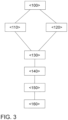
- FIG 3 is a flow chart for carrying out a method according to the invention for exhaust gas aftertreatment of an internal combustion engine 10 with the Figure 1 shown exhaust gas aftertreatment system.
- the lambda control is initially carried out in a first process step ⁇ 110> via the first lambda probe 38, also referred to as the guide probe.
- the electrically heatable catalyst 36 is heated up with the aim of using this catalyst 36 as quickly as possible.
- the third lambda probe 42 downstream of the electrically heatable catalyst 36 is used for the trim control. If the electrically heatable catalyst 36 has reaches its light-off temperature, the heating of this catalyst 36 is deactivated in a next method step ⁇ 130>. This can lead to the electrically heatable catalyst 36 cooling below its light-off temperature, particularly in a low-load phase of the internal combustion engine 10. In this case, the lambda control is switched to the second lambda probe 40 downstream of the first catalyst 28 close to the engine in a next method step ⁇ 140>.
- the lambda control is adjusted back to the third lambda probe 42 in a method step ⁇ 160>.
- the third catalyst 32 in the exhaust system 20 serves to prevent emissions breakthroughs during the on-board diagnosis of the third lambda probe. This third catalyst 32 is not actively integrated into the lambda control.
- the electrically heated catalyst 36 can be heated up to its light-off temperature again by reactivating the electrical heating element 52. This ensures that the catalytic activity of this catalyst 36 is maintained even in low-load phases.
- the lambda control can be extended to the third lambda probe 42 again. This method can be used to maximize the active catalyst volume within the control system of the lambda control.
Landscapes
- Engineering & Computer Science (AREA)
- Chemical & Material Sciences (AREA)
- Combustion & Propulsion (AREA)
- Mechanical Engineering (AREA)
- General Engineering & Computer Science (AREA)
- Chemical Kinetics & Catalysis (AREA)
- Health & Medical Sciences (AREA)
- Toxicology (AREA)
- Materials Engineering (AREA)
- Exhaust Gas After Treatment (AREA)
Description
- Die Erfindung betrifft ein Verfahren zur Abgasnachbehandlung eines Verbrennungsmotors sowie ein Abgasnachbehandlungssystem zur Durchführung eines solchen Verfahrens gemäß den Oberbegriffen der unabhängigen Patentansprüche.
- Künftige Abgasgesetzgebungen stellen hohe Anforderungen an motorische Rohemissionen und an die Abgasnachbehandlung von Verbrennungsmotoren. Mit Einführung der Abgasgesetzgebung Euro 6d-Temp müssen die Kraftfahrzeuge die Emissionsgrenzen in einem realitätsnahen Betrieb (Real Driving Emissions) einhalten. Der Einsatz von mehrstufigen Abgasnachbehandlungskonzepten im Ottomotor-Umfeld wirft für neue Abgasvorschriften Fragen hinsichtlich der Regelbarkeit der verschiedenen Abgasnachbehandlungskomponenten sowie der Regelgüte und Betriebsbereitschaft der Abgasnachbehandlungskomponenten auf. Ein Forschungskonzept mit einer Abgasanlage, welche bereits für eine mehrstufige Abgasnachbehandlung vorgesehen ist, zeigt auf, dass hier ein Lambdaregelungskonzept benötigt wird, welches die Besonderheiten der jeweiligen Abgasnachbehandlungskomponenten kennt und diese bei ihrem Regelverhalten berücksichtigt. Weiter besteht die Herausforderung darin, dass jede Abgasnachbehandlungskomponente eigene Randbedingungen für eine optimale Konvertierung der Schadstoffkomponenten im Abgas benötigt, um eine maximal effiziente Abgasnachbehandlung zu ermöglichen. Dabei zeigt sich, dass ein aus dem Stand der Technik bekanntes Lambdaregelungskonzept mit starr ausgelegtem Regelsystem nur suboptimale Emissionsergebnisse liefert.
- Aus der
DE 10 2010 002 586 A1 ist ein Verfahren zum Betreiben eines Verbrennungsmotors für ein Kraftfahrzeug mit einem Abgassystem bekannt, in welchem mindestens ein Katalysator und wenigstens eine Lambdasonde angeordnet sind. Der Verbrennungsmotor wird nach einem Kaltstart zum Aufheizen des Katalysators im Wechsel mit magerem und fettem Kraftstoff-Luft-Gemisch betrieben. Die Lambdasonde wird nach dem Kaltstart so beheizt, dass sie nach maximal zehn Sekunden betriebsbereit ist und der Verbrennungsmotor mit einer auf einem Signal der Lambdasonde basierenden Zweipunktregelung betrieben wird. Dabei wird ein Wechsel zwischen dem Betrieb mit magerem Kraftstoff-Luft-Gemisch und mit fettem Kraftstoff-Luft-Gemisch jeweils durch das Signal der Lambdasonde ausgelöst. - Aus der
DE 10 2013 201 734 A1 ist ein Verfahren zum Betreiben einer Lambdasondenanordnung im Abgassystem eines Verbrennungsmotors mit wenigstens einer ersten Lambdasonde stromaufwärts eines Katalysators und wenigstens einer zweiten Lambdasonde stromabwärts des Katalysators bekannt. Dabei ist die zweite Lambdasonde als Sprungsonde ausgebildet. Dabei werden eine Diagnose eines Kennlinienoffsets der ersten Lambdasonde und gegebenenfalls eine Adaption eines Kennlinienoffsetfehlers vorgenommen. Dabei wird für die Diagnose bei aktiver Lambdaverstellung ein Wert, welcher die Sauerstoffspeicherfähigkeit des Katalysators repräsentiert, und ein weiterer Wert, der die Sauerstoffaustragungsfähigkeit aus dem Katalysator repräsentiert, erfasst. Aus dem Verhältnis von Sauerstoffspeicherfähigkeit und Sauerstoffaustragungsfähigkeit wird ein Kennlinienoffset der ersten Lambdasonde berechnet. - Die
EP 2 884 066 A1 offenbart ein Verfahren zur Diagnose eines Gegenstandes wie eines Katalysators oder eines Filters. Um eine besonders genaue Aussage über eine Funktion des Katalysators zu erhalten, ist dabei vorgesehen, dass zur Messung einer katalytischen Reaktivität eine Stirnseite des Katalysators mit einem Prüfmedium mit definierter Zusammensetzung wie Propangas oder Kohlenmonoxid mittels einer Einrichtung durch eine Öffnung beaufschlagt wird und an einer stromabwärts gelegenen Position eine Konzentration von zumindest einem reduzierten oder oxidierten Bestandteil des Prüfmediums nach Passieren des Katalysators gemessen wird. Eine solche Beaufschlagung mit einem definiert zusammengesetzten (Ab-)Gas ist jedoch nur im Laborbetrieb möglich. Daher eignet sich ein solches Verfahren nicht zur Optimierung der Emissionen im realen Fahrbetrieb. - Aus der
DE 10 2005 054 733 A1 ist ein Verbrennungsmotor mit einem Abgasnachbehandlungssystem bekannt, in welchem ein Abgasbrenner angeordnet ist, mit welchem das Aufheizen eines Drei-Wege-Katalysators im Abgasnachbehandlungssystem beschleunigt werden kann. Dabei ist vorgesehen, dass der Abgasbrenner in einer Kaltstartphase des Verbrennungsmotors betrieben wird und zumindest solange aktiviert bleibt, bis der Drei-Wege-Katalysator seine Light-Off-Temperatur erreicht hat. - Die
DE 10 2012 011 113 A1 offenbart eine Abgasanlage für einen Verbrennungsmotor mit mindestens zwei strömungstechnisch in Reihe geschalteten Abgasnachbehandlungskomponenten, wobei die hintere der beiden Abgasnachbehandlungskomponenten mittels eines elektrischen Heizelements beheizbar ist. - Die
DE 10 2017 100 892 A1 offenbart ein Verfahren zur Regeneration eines Partikelfilters in der Abgasanlage eines Verbrennungsmotors. Dabei ist vorgesehen, dass während eines Magerbetriebs des Verbrennungsmotors zur Bereitstellung des Sauerstoffs zur Regeneration des Partikelfilters die durch einen Drei-Wege-Katalysator nicht mehr konvertierbaren Stickoxide in einem Stickoxid-Speicherkatalysator eingelagert werden. - Aus der
US 2008 / 282 673 A1 ist ein Verfahren zur Steuerung eines Verbrennungsmotors in einem Hybridantrieb bekannt. Dabei wird zunächst ermittelt, ob Kaltstartbedingungen für den Verbrennungsmotor vorliegen und bei Kaltstartbedingungen ein elektrisch beheizbarer Katalysator aktiviert. Sobald der elektrisch beheizbare Katalysator eine Schwellentemperatur erreicht hat, wird der Verbrennungsmotor zugeschaltet. - Der Erfindung liegt nun die Aufgabe zugrunde, die Konvertierungsleistung des Abgasnachbehandlungssystem weiter zu verbessern und insbesondere die Lambdaregelung derart anzupassen, dass die Effizienz der Abgasnachbehandlungskomponenten weiter gesteigert werden kann.
- Erfindungsgemäß wird diese Aufgabe durch ein Verfahren zur Abgasnachbehandlung eines Verbrennungsmotors, dessen Auslass mit einer Abgasanlage verbunden ist, gelöst. Dabei sind in der Abgasanlage in Strömungsrichtung eines Abgases durch die Abgasanlage ein erster Katalysator, stromabwärts des ersten Katalysators ein zweiter Katalysator und stromabwärts des zweiten Katalysators ein dritter Katalysator angeordnet. In einem Abgaskanal der Abgasanlage sind stromaufwärts des ersten Katalysators eine erste Lambdasonde und stromabwärts des ersten Katalysators und stromaufwärts des zweiten Katalysators eine zweite Lambdasonde angeordnet, wobei stromabwärts des zweiten Katalysators und stromaufwärts des dritten Katalysators eine dritte Lambdasonde angeordnet ist. Dabei sind der erste Katalysator und der dritte Katalysator als Drei-Wege-Katalysatoren ausgeführt. Der zweite Katalysator ist als ein mittels eines elektrischen Heizelements aktiv elektrisch beheizbarer Drei-Wege-Katalysator ausgeführt. Das Verfahren umfasst folgende Schritte:
- Aktives Beheizen eines Katalysators stromabwärts des ersten Katalysators;
- Vergleich der Bauteiltemperatur des jeweiligen Katalysators, nämlich des ersten Katalysators, des zweiten Katalysators und des dritten Katalysators, mit der jeweiligen Light-Off-Temperatur des Katalysators;
- Regeln des Verbrennungsluftverhältnisses über die Lambdaregelung des Verbrennungsmotors mittels derjenigen Lambdasonde stromabwärts des letzten Katalysators, welcher seine Light-Off-Temperatur erreicht hat, wobei
- die Lambdaregelung über die erste Lambdasonde erfolgt, wenn keiner der Katalysatoren seine Light-Off-Temperatur erreicht hat, und wobei
- die Lambdaregelung auf die Lambdasonde stromabwärts des zweiten Katalysators ausgeweitet wird, sobald dieser Katalysator seine Light-Off-Temperatur erreicht hat.
- Jede Vorrichtung zur katalytischen Abgasreinigung benötigt zum Erreichen einer Wirksamkeit das Überschreiten einer Mindesttemperatur, der sogenannten Light-off-Temperatur. Durch das erfindungsgemäße Verfahren kann zeitnah nach einer passiver Aufheizung bedingt durch den vom Fahrer aufgeprägten Lastzustand ein zusätzliches Katalysatorvolumen zur Konvertierung der Schadstoffkomponenten bereitgestellt werden. Dies ist insbesondere bei höherlastigen Fahrprofilen von Bedeutung, da in diesem Fall die katalytisch wirkende Oberfläche optimal genutzt wird. Durch die Lambdaregelung auf die jeweils letzte Lambdasonde unmittelbar stromabwärts eines Katalysators, welcher seine Light-Off-Temperatur erreicht hat, erfolgt eine möglichst effiziente Nutzung des aktiven Katalysatorvolumens. Dadurch ist eine besonders effiziente Konvertierung der Schadstoffe möglich, wodurch die Endrohremissionen minimiert werden können.
- Durch die in den abhängigen Ansprüchen angegebenen Merkmale sind vorteilhafte Verbesserungen und Weiterentwicklungen des im unabhängigen Anspruch angegebenen Verfahrens möglich.
- In bevorzugter Ausgestaltung der Erfindung ist vorgesehen, dass ab dem Motorstart des Verbrennungsmotors eine Lambdaregelung durch die erste Lambdasonde erfolgt. Durch eine Lambdaregelung auf ein stöchiometrisches Verbrennungsluftverhältnis in der Kaltstartphase können die Rohemissionen des Verbrennungsmotors minimiert werden, insbesondere dann, wenn noch keiner der Katalysatoren seine Light-Off-Temperatur erreicht hat und eine Abgasnachbehandlung des Abgases durch die Katalysatoren noch nicht möglich ist. Erfindungsgemäß ist vorgesehen, dass die Lambdaregelung auf die Lambdasonde stromabwärts des aktiv beheizbaren Katalysators ausgeweitet wird, sobald dieser Katalysator seine Light-Off-Temperatur erreicht hat. Durch die Ausweitung der Lambdaregelung auf die Lambdasonde stromabwärts des aktiv beheizbaren Katalysators wird das zur Verfügung stehende katalytisch wirksame Abgasnachbehandlungsvolumen vergrößert. Da die Konvertierungsleistung bei noch vergleichsweise kalten Katalysatoren begrenzt ist, kann hierdurch die Effizienz der Abgasnachbehandlung in der Kaltstartphase deutlich verbessert werden. Zudem kann durch das aktive Beheizen sichergestellt werden, dass der aktiv beheizbare Katalysator möglichst schnell nach einem Kaltstart des Verbrennungsmotors seine Light-Off-Temperatur erreicht und somit die im Abgas enthaltenden Schadstoffkomponenten in unlimitierte Abgaskomponenten konvertieren kann.
- In weiterer bevorzugter Ausgestaltung der Erfindung ist vorgesehen, dass das aktive Beheizen eingestellt wird, sobald der Katalysator seine Light-Off-Temperatur erreicht hat. Dadurch kann der Energiebedarf des Abgasnachbehandlungssystems reduziert und eine Batterie des Kraftfahrzeuges entlastet werden. Das weitere Aufheizen des Katalysators erfolgt dann durch die exotherme Reaktion der Abgaskomponenten an der Oberfläche des Katalysators.
- In einer bevorzugten Ausführungsform des Verfahrens ist vorgesehen, dass die Lambdaregelung durch die erste Lambdasonde und die zweite Lambdasonde stromaufwärts und stromabwärts des ersten Katalysators erfolgt, wenn im Betrieb des Verbrennungsmotors die Temperatur des aktiv beheizbaren Katalysators unter seine Light-Off-Temperatur absinkt. Dadurch kann die Lambdaregelung an das jeweils katalytisch wirksame Volumen der Katalysatoren angepasst werden, sodass die Lambdaregelung auf diejenigen Katalysatoren erfolgt, welche eine effiziente Konvertierung der limitierten gasförmigen Schadstoffkomponenten ermöglichen.
- Besonders vorteilhaft ist dabei, wenn das aktive Beheizen wieder aktiviert wird, wenn die Temperatur des aktiv beheizbaren Katalysators im Betrieb des Verbrennungsmotors unter seine Light-Off-Temperatur abgefallen ist. Durch das aktive Beheizen kann der aktiv beheizbare Katalysator wieder auf seine Light-Off-Temperatur aufgeheizt werden, sodass das zur Verfügung stehende katalytisch wirksame Katalysatorvolumen vergrößert wird. Dadurch kann die Konvertierungsleistung des Abgasnachbehandlungssystems verbessert und die Endrohremissionen verringert werden.
- In einer vorteilhaften Verbesserung des Verfahrens ist vorgesehen, dass ein zu erwartendes Lastprofil des Verbrennungsmotors ermittelt wird und der aktiv beheizbare Katalysator beheizt wird, wenn anhand des zu erwartenden Lastprofils ein Absinken der Bauteiltemperatur des aktiv beheizbaren Katalysators unter seine Light-Off-Temperatur anzunehmen ist. So kann beispielsweise das Fahrverhalten des Fahrzeugführers ermittelt werden und/oder bevorzugte Fahrstrecken des Fahrzeugführers erkannt werden. Dies kann beispielsweise anhand der Navigationsdaten des Kraftfahrzeuges oder einer Auswertung der Motordaten erfolgen. Wird erkannt, dass der zu erwartende nächste Fahrabschnitt voraussichtlich mit einem Schwachlastbetrieb des Verbrennungsmotors durchfahren wird, bei welchem die Temperatur des elektrisch beheizbaren Katalysators unter seine Light-Off-Temperatur absinkt, so wird der beheizbare Katalysator beheizt, um weiterhin ein größtmögliches aktives Katalysatorvolumen zur Verfügung zu stellen.
- Erfindungsgemäß wird ein Abgasnachbehandlungssystem für einen Verbrennungsmotor, welches an einen Auslass des Verbrennungsmotors anschließbar ist, vorgeschlagen. Das Abgasnachbehandlungssystem umfasst eine Abgasanlage, in welcher in Strömungsrichtung eines Abgases durch die Abgasanlage ein erster Katalysator, stromabwärts des ersten Katalysators ein zweiter Katalysator und stromabwärts des zweiten Katalysator ein dritter Katalysator angeordnet sind. Dabei sind in einem Abgaskanal der Abgasanlage stromaufwärts des ersten Katalysator eine erste Lambdasonde und stromabwärts des ersten Katalysators und stromaufwärts des zweiten Katalysators ein zweite Lambdasonde angeordnet ist. Ferner ist stromabwärts des zweiten Katalysators und stromaufwärts des dritten Katalysators eine dritte Lambdasonde angeordnet. Dabei sind der erste Katalysator und der dritte Katalysator als Drei-Wege-Katalysatoren ausgeführt. Der zweite Katalysator ist als ein mittels eines elektrischen Heizelements aktiv elektrisch beheizbarer Drei-Wege-Katalysator ausgeführt.. Das Abgasnachbehandlungssystem umfasst zusätzlich ein Steuergerät, welches dazu eingerichtet ist, ein erfindungsgemäßes Verfahren durchzuführen, wenn ein maschinenlesbarer Programmcode durch das Steuergerät ausgeführt wird. Durch ein solches Abgasnachbehandlungssystem ist es möglich, die Konvertierungsleistung der Katalysatoren zu verbessern und die Emissionen zu verringern.
- In einer vorteilhaften Weiterentwicklung der Erfindung ist vorgesehen, dass stromabwärts des ersten Katalysators und stromaufwärts des zweiten Katalysators ein vierter Katalysator angeordnet ist. Durch einen zusätzlichen Katalysator kann das zur Verfügung stehende katalytisch wirksame Katalysatorvolumen vergrößert werden. Dies hat nicht nur in der Kaltstartphase, in welcher die katalytische Aktivität der Katalysatoren noch eingeschränkt ist, Vorteile, sondern auch bei einem Volllastbetrieb des Verbrennungsmotors. Zudem unterliegen Katalysatoren einem Alterungsprozess, wodurch die Konvertierungsleistung über die Lebenszeit des Katalysators abnimmt. Durch einen zusätzlichen Katalysator wird hier eine Reserve geschaffen, welche dafür sorgt, dass auch bei einer deutlichen Alterung der Katalysatoren noch ein hinreichendes Katalysatorvolumen vorliegt, um in allen Betriebssituationen des Verbrennungsmotors eine vollständige Konvertierung der limitierten Abgaskomponenten zu ermöglichen.
- Besonders bevorzugt ist dabei, wenn der vierte Katalysator im Wesentlichen frei von einer sauerstoffspeicherfähigen Komponente ausgeführt ist. Durch eine Ausführung des vierten Katalysators mit einem Washcoat, welcher im Wesentlichen frei von einer sauerstoffspeicherfähigen Komponente ausgeführt ist, können der vierte Katalysator und der zweite Katalysator gemeinsam über eine Lambdasonde geregelt werden. Zudem wird die Regelung nicht durch das Befüllen und Entleeren eines zusätzlichen Sauerstoffspeichers verlangsamt, wodurch die Effizienz der Abgasnachbehandlung weiter gesteigert werden kann.
- Erfindungsgemäß ist vorgesehen, dass der aktiv beheizbare Katalysator ein elektrisches Heizelement umfasst. Ein elektrisches Heizelement, insbesondere eine elektrische Heizscheibe, kann einfach und kostengünstig in den aktiv beheizbaren Katalysator integriert werden. Alternativ kann ein solches Heizelement dem aktiv beheizbaren Katalysator unmittelbar vorgeschaltet werden. Ein elektrisches Heizelement hat gegenüber dem Beheizen mittels eines Abgasbrenners den Vorteil, dass es vergleichsweise wenig Bauraum benötigt und somit einfach und mit geringen Mehrkosten in die Abgasanlage integriert werden kann.
- In einer vorteilhaften Verbesserung des Abgasnachbehandlungssystems ist vorgesehen, dass die erste Lambdasonde als Breitbandsonde und die weiteren Lambdasonden jeweils als Sprungsonden ausgeführt sind. Durch eine Breitbandsonde kann eine quantitative Bestimmung des Verbrennungsluftverhältnisses im Abgaskanal erfolgen. Durch die Sprungsonden kann ein Durchbruch durch den jeweiligen Katalysator erkannt werden, um im Rahmen der Lambdaregelung das Verbrennungsluftverhältnis entsprechend anzupassen.
- In einer bevorzugten Ausführungsform der Erfindung ist vorgesehen, dass in der Abgasanlage ein Temperatursensor angeordnet ist. Durch einen Temperatursensor in der Abgasanlage kann die Abgastemperatur und/oder die Bauteiltemperatur eines Katalysators ermittelt werden. Dadurch ist es leichter zu erkennen, ob der jeweilige Katalysator seine Light-Off-Temperatur erreicht hat. Insbesondere kann der Temperatursensor auch genutzt werden, um in einem Berechnungsmodell zur Bestimmung der Bauteiltemperaturen Informationen zu liefern und das Berechnungsmodell zu verbessern.
- Die verschiedenen in dieser Anmeldung genannten Ausführungsformen der Erfindung sind, sofern im Einzelfall nicht anders ausgeführt, mit Vorteil miteinander kombinierbar.
- Die Erfindung wird nachfolgend in Ausführungsbeispielen anhand der zugehörigen Zeichnungen erläutert. Es zeigen:
- Figur 1
- ein Ausführungsbeispiel eines Verbrennungsmotors mit einem erfindungsgemäßen Abgasnachbehandlungssystem.
- Figur 2
- ein weiteres Ausführungsbeispiel für einen Verbrennungsmotor mit einem erfindungsgemäßen Abgasnachbehandlungssystem; und
- Figur 3
- ein Ablaufdiagramm zur Durchführung eines erfindungsgemäßen Verfahrens zur Abgasnachbehandlung eines Verbrennungsmotors.
-
Figur 1 zeigt einen Verbrennungsmotor 10 mit einem Abgasnachbehandlungssystem in einer schematischen Darstellung. Der Verbrennungsmotor 10 weist eine Mehrzahl von Brennräumen 12 auf, an welchen jeweils eine Zündkerze 14 angeordnet ist. Der Verbrennungsmotor 10 weist einen Einlass 16 auf, mit welchem der Verbrennungsmotor 10 mit einem aus Gründen der Übersichtlichkeit nicht dargestellten Luftversorgungssystem verbindbar ist. Der Verbrennungsmotor 10 weist ferner einen Auslass 18 auf, mit welchem der Verbrennungsmotor 10 mit einer Abgasanlage 20 verbunden ist, derart, dass ein Abgas aus den Brennräumen 12 des Verbrennungsmotors 10 in die Abgasanlage 20 geleitet werden kann. Die Abgasanlage 20 umfasst einen Abgaskanal 22, in welchem in Strömungsrichtung eines Abgases des Verbrennungsmotors 10 durch den Abgaskanal 22 eine Turbine 26 eines Abgasturboladers 24, stromabwärts der Turbine 26 ein erster Katalysator 28, stromabwärts des ersten Katalysators 28 ein zweiter Katalysator 30 und weiter stromabwärts ein dritter Katalysator 32 angeordnet sind. Der erste Katalysator 28 ist vorzugsweise als Drei-Wege-Katalysator ausgeführt und in einer motornahen Position in der Abgasanlage 20 angeordnet. Unter einer motornahen Position wird in diesem Zusammenhang eine Position mit einer Abgaslauflänge von weniger als 80 cm, vorzugsweise von weniger als 50 cm ab dem Auslass 18 des Verbrennungsmotors 10 verstanden. Der zweite Katalysator 30 ist als mittels eines elektrischen Heizelements 52 aktiv beheizbarer Drei-Wege-Katalysator 36 ausgeführt. Der dritte Katalysator 32 ist vorzugsweise in einer Unterbodenposition eines Kraftfahrzeuges angeordnet und ebenfalls als Drei-Wege-Katalysator ausgeführt. - Stromabwärts der Turbine 26 des Abgasturboladers 34 und stromaufwärts des ersten Katalysators 28 ist im Abgaskanal 22 eine erste Lambdasonde 38 angeordnet. Die erste Lambdasonde 38 ist vorzugsweise als Breitbandsonde 44 ausgeführt und ermöglicht somit eine quantitative Beurteilung des Verbrennungsluftverhältnisses stromaufwärts des ersten Katalysators 28. Stromabwärts des ersten Katalysators 28 und stromaufwärts des zweiten Katalysators 30 ist im Abgaskanal 22 eine zweite Lambdasonde 40 vorgesehen, welche vorzugsweise als Sprungsonde 46 ausgeführt ist. Stromabwärts des zweiten Katalysators 30 und stromaufwärts des dritten Katalysators 32 ist im Abgaskanal 22 eine dritte Lambdasonde 42 angeordnet, welche vorzugsweise als Sprungsonde 46 ausgeführt ist. Ferner kann im Abgaskanal 22 ein Temperatursensor 48 angeordnet sein, um die Abgastemperatur zu messen und somit die Bauteiltemperatur der Katalysatoren 28, 30, 32 zu berechnen.
- Alternativ zu einem elektrischen Heizelement 52, welches dem Katalysator 30, 32 vorgeschaltet ist, kann bei einer nicht zur Erfindung gehörenden Ausführung des aktiv beheizbaren Katalysators 36 als Vier-Wege-Katalysator 54 auch das Filtersubstrat 56 des Partikelfilters 54 elektrisch leitend und somit direkt beheizbar ausgeführt sein.
- Der Verbrennungsmotor 10 sowie die Lambdasonden 38, 40, 42 und der Temperatursensor 48 sind über Signalleitungen mit einem Motorsteuergerät 50 verbunden. Anhand der Informationen der Lambdasonden 38, 40, 42 und des Temperatursensors 48 werden die Einspritzmenge, der Einspritzzeitpunkt und der Zündzeitpunkt in den Brennräumen 12 gesteuert, um eine möglichst emissionsarme Verbrennung des Kraftstoff-Luft-Gemischs gewährleisten zu können.
- Um die Emissionen des Verbrennungsmotors 10 nach einem Kaltstart zu minimieren ist, die schnelle Bereitstellung eines möglichst großen aktiven Katalysatorvolumens essentiell. Darüber hinaus ist zur Verbesserung der Konvertierungsleistung auch eine Anpassung der stetigen Lambdaregelung mittels einer Trimregelung notwendig, deren Regelstrecke nicht nur, wie bei aus dem Stand der Technik bekannten Lambdaregelungen, auf den ersten Katalysator 28 beschränkt ist, sondern eine Regelung auf das gesamte aktive Katalysatorvolumen ermöglicht. Zur Einbindung einer zusätzlichen Lambdasonde 40, 42 in die Regelstecke der Trimregelung muss der stromaufwärts dieser Lambdasonde 40, 42 angeordnete Katalysator 30, 32 seine Light-Off-Temperatur erreicht haben. Da dies bei einer motorfernen Position des Katalysators 30, 32, insbesondere in einer Unterbodenposition eines Kraftfahrzeuges, nicht in allen Betriebssituationen gewährleistet ist, wird der zweite Katalysator 40 mittels eines elektrischen Heizelements 52 nach dem Motorstart des Verbrennungsmotors 10 oder in schwachlastigen Betriebssituationen des Verbrennungsmotors 10 extern beheizt. Die Heizmaßnahmen können zur Senkung des Gesamtenergiebedarfs und zur Schonung einer Batterie des Kraftfahrzeuges reduziert oder abgeschaltet werden, wenn der motornahe erste Katalysator 28 seine Light-Off-Temperatur erreicht hat und die zweite Lambdasonde 40 stromabwärts des ersten Katalysators 28 zur Lambdaregelung hinzugezogen werden kann. Sobald der aktiv beheizbare Katalysator 36 durch den Motorbetrieb des Verbrennungsmotors 10 seine Light-Off-Temperatur erreicht hat, sollte die Lambdareglung wieder auf die dritte Lambdasonde 42 ausgedehnt werden. Die Realisierung der Variabilität in der Regelstrecke der Lambdaregelung erfordert eine intelligente Detektion des bereits aktiven Katalysatorvolumens. Dies kann beispielsweise durch ein im Motorsteuergerät 50 des Verbrennungsmotors 10 abgelegtes Berechnungsmodell erfolgen.
- In
Figur 2 ist ein alternatives Ausführungsbeispiel eines erfindungsgemäßen Abgasnachbehandlungssystems dargestellt. Bei im Wesentlichen gleichem Aufbau wie zuFigur 1 ausgeführt, ist in diesem Ausführungsbeispiel stromabwärts des ersten Katalysators 28 und stromaufwärts des zweiten Katalysators 30 ein vierter Katalysator 34 angeordnet. Der vierte Katalysator 34 ist vorzugsweise als Drei-Wege-Katalysator mit einem Washcoat ausgeführt, welcher im Wesentlichen frei von einer sauerstoffspeicherfähigen Komponente ausgeführt ist. Dadurch kann das Katalysatorvolumen erhöht werden, ohne eine zusätzliche Lambdasonde stromabwärts dieses vierten Katalysators zu benötigen. Durch den Washcoat ohne Sauerstoffspeicherfähigkeit ist eine gemeinsame Regelung des vierten Katalysators 34 und des beheizbaren zweiten Katalysators 30, 36 über die dritte Lambdasonde 42 möglich. Alternativ kann auch eine weitere Lambdasonde vorgesehen sein, wobei die Regelstrecke der Lambdaregelung auf die in Strömungsrichtung jeweils letzte Lambdasonde 38, 40, 42 ausgedehnt wird, deren unmittelbar stromaufwärts liegender Katalysator 28, 30, 32 seine Light-Off-Temperatur erreicht hat. Hat keiner der Katalysatoren 28, 30, 32 seine Light-Off-Temperatur erreicht, so erfolgt die Lambdaregelung über die erste Lambdasonde 38. Neben einer verbesserten Konvertierungsleistung durch ein vergrößertes Katalysatorvolumen durch den zusätzlichen vierten Katalysator 34 hat das inFigur 2 vorgeschlagene Abgasnachbehandlungssystem auch den Vorteil einer erhöhten Alterungsbeständigkeit. - In
Figur 3 ist ein Ablaufdiagramm zur Durchführung eines erfindungsgemäßen Verfahrens zur Abgasnachbehandlung eines Verbrennungsmotors 10 mit dem inFigur 1 dargestellten Abgasnachbehandlungssystem gezeigt. Bei einem Kaltstart <100> des Verbrennungsmotors 10 erfolgt die Lambdaregelung zunächst in einem ersten Verfahrensschritt <110> über die auch als Führungssonde bezeichnete erste Lambdasonde 38. Dabei wird das Verbrennungsluftverhältnis des Verbrennungsmotors 10 auf ein stöchiometrisches Verbrennungsluftverhältnis (λ = 1) eingeregelt. Gleichzeitig erfolgt in einem Verfahrensschritt <120> ein Aufheizen des elektrisch beheizbaren Katalysators 36 mit dem Ziel der möglichst schnellen Nutzung dieses Katalysators 36. Hat der elektrisch beheizbare Katalysator 36 seine Light-Off-Temperatur erreicht, was durch eine Temperaturmessung oder ein im Steuergerät 50 abgelegtes Berechnungsmodell ermittelt werden kann, wird die dritte Lambdasonde 42 stromabwärts des elektrisch beheizbaren Katalysators 36 für die Trimregelung genutzt. Hat der elektrisch beheizbare Katalysator 36 seine Light-Off-Temperatur erreicht, wird in einem nächsten Verfahrensschritt <130> das Beheizen dieses Katalysators 36 deaktiviert. Dies kann insbesondere in einer Schwachlastphase des Verbrennungsmotors 10 zu einem Abkühlen des elektrisch beheizbaren Katalysators 36 unter seine Light-Off-Temperatur führen. In diesem Fall wird die Lambdaregelung in einem nächsten Verfahrensschritt <140> auf die zweite Lambdasonde 40 stromabwärts des motornahen ersten Katalysators 28 umgeschaltet. Wird der elektrisch beheizbare Katalysator 36 im weiteren Betrieb <150> des Verbrennungsmotors 10 durch das Abgas des Verbrennungsmotors 10 wieder auf seine Light-Off-Temperatur aufgeheizt, so wird die Lambdaregelung in einem Verfahrensschritt <160> wieder auf die dritte Lambdasonde 42 verstellt. Der dritte Katalysator 32 in der Abgasanlage 20 dient der Verhinderung von Emissionsdurchbrüchen während der On-Board-Diagnose der dritten Lambdasonde. Dieser dritte Katalysator 32 ist nicht aktiv in die Lambdaregelung mit eingebunden. - Wird der Verbrennungsmotor 10 in einem Schwachlastbetrieb betrieben, kann der elektrisch beheizbare Katalysator 36 durch ein erneutes Aktivieren des elektrischen Heizelements 52 wieder auf seine Light-Off-Temperatur aufgeheizt werden. Somit kann die katalytische Aktivität dieses Katalysators 36 auch in Schwachlastphasen sichergestellt werden. Hat der elektrisch beheizbare Katalysator 36 wieder seine Light-Off-Temperatur erreicht, kann die Lambdaregelung wieder auf die dritte Lambdasonde 42 ausgedehnt werden. Mit dieser Methode kann das aktive Katalysatorvolumen innerhalb der Regelstrecke der Lambdaregelung maximiert werden.
-
- 10
- Verbrennungsmotor
- 12
- Brennraum
- 14
- Zündkerze
- 16
- Einlass
- 18
- Auslass
- 20
- Abgasanlage
- 22
- Abgaskanal
- 24
- Abgasturbolader
- 26
- Turbine
- 28
- erster Katalysator
- 30
- zweiter Katalysator
- 32
- dritter Katalysator
- 34
- vierter Katalysator
- 36
- aktiv beheizbarer Katalysator
- 38
- erste Lambdasonde
- 40
- zweite Lambdasonde
- 42
- dritte Lambdasonde
- 44
- Breitbandsonde
- 46
- Sprungsonde
- 48
- Temperatursensor
- 50
- Motorsteuergerät
- 52
- elektrisches Heizelement
- 54
- Vier-Wege-Katalysator
- 56
- Filtersubstrat
Claims (11)
- Verfahren zur Abgasnachbehandlung eines Verbrennungsmotors (10), dessen Auslass (18) mit einer Abgasanlage (20) verbunden ist, wobei in der Abgasanlage (20) in Strömungsrichtung eines Abgases durch die Abgasanlage (20) ein erster Katalysator (28), stromabwärts des ersten Katalysators (28) ein zweiter Katalysator (30) und stromabwärts des zweiten Katalysator (30) ein dritter Katalysator (32) angeordnet sind, wobei in einem Abgaskanal (22) der Abgasanlage (20) stromaufwärts des ersten Katalysators (28) eine erste Lambdasonde (38) und stromabwärts des ersten Katalysators (28) und stromaufwärts des zweiten Katalysators (30) eine zweite Lambdasonde (40) angeordnet ist, wobei stromabwärts des zweiten Katalysators (30) und stromaufwärts des dritten Katalysators (32) eine dritte Lambdasonde (42) angeordnet ist, wobei der erste Katalysator (28) und der dritte Katalysator (32) als Drei-Wege-Katalysatoren ausgeführt sind, und wobei der zweite Katalysator (30) als ein mittels eines elektrischen Heizelements (52) aktiv elektrisch beheizbarer Drei-Wege-Katalysator (36) ausgeführt ist, umfassend folgende Schritte:- Aktives Beheizen des zweiten Katalysators (30) stromabwärts des ersten Katalysators (28),- Vergleichen der Bauteiltemperatur des ersten Katalysators (28), des zweiten Katalysators (30) und des dritten Katalysators (32) mit der jeweiligen Light-Off-Temperatur des Katalysators (28, 30, 32,),- Regeln des Verbrennungsluftverhältnisses über einer Lambdaregelung des Verbrennungsmotors (10) mittels derjenigen Lambdasonde (38, 40, 42) stromabwärts des letzten Drei-Wege-Katalysators (28, 30, 32), welcher seine Light-Off-Temperatur erreicht hat, wobei- die Lambdaregelung über die erste Lambdasonde (38) erfolgt, wenn keiner der Katalysatoren (28, 30, 32) seine Light-Off-Temperatur erreicht hat, und wobei- die Lambdaregelung auf die Lambdasonde (40) stromabwärts des zweiten Katalysators (30) ausgeweitet wird, sobald dieser Katalysator (30) seine Light-Off-Temperatur erreicht hat.
- Verfahren zur Abgasnachbehandlung nach Anspruch 1, dadurch gekennzeichnet, dass ab einem Motorstart des Verbrennungsmotors (10) eine Lambdaregelung durch die erste Lambdasonde (38) erfolgt.
- Verfahren zur Abgasnachbehandlung nach einem der Ansprüche 1 oder 2, dadurch gekennzeichnet, dass das aktive Beheizen eingestellt wird, sobald der zweite Katalysator (30) seine Light-Off-Temperatur erreicht hat.
- Verfahren zur Abgasnachbehandlung nach einem der Ansprüche 1 bis 3, dadurch gekennzeichnet, dass die Lambdaregelung durch die erste Lambdasonde (38) und die zweite Lambdasonde (40) stromaufwärts und stromabwärts des ersten Katalysators (28) erfolgt, wenn im Betrieb des Verbrennungsmotors (10) die Temperatur des aktiv beheizbaren Katalysators (36) unter seine Light-Off-Temperatur absinkt.
- Verfahren zur Abgasnachbehandlung nach Anspruch 4, dadurch gekennzeichnet, dass das aktive Beheizen wieder aktiviert wird, wenn die Temperatur des aktiv beheizbaren Katalysators (36) im Betrieb des Verbrennungsmotors (10) unter seine Light-Off-Temperatur abgefallen ist.
- Verfahren zur Abgasnachbehandlung nach einem der Ansprüche 1 bis 5, dadurch gekennzeichnet, dass ein zu erwartendes Lastprofil des Verbrennungsmotors (10) ermittelt wird und der aktiv beheizbare Katalysator (36) beheizt wird, wenn anhand des zu erwartenden Lastprofils ein Absinken der Bauteiltemperatur des aktiv beheizbaren Katalysators (36) unter seine Light-Off-Temperatur anzunehmen ist.
- Abgasnachbehandlungssystem für einen Verbrennungsmotor (10), welches an einen Auslass (18) des Verbrennungsmotors (10) anschließbar ist, wobei das Abgasnachbehandlungssystem eine Abgasanlage (20) umfasst, in welcher in Strömungsrichtung eines Abgases durch die Abgasanlage (20) ein erster Katalysator (28), stromabwärts des ersten Katalysators (28) ein zweiter Katalysator (30) und stromabwärts des zweiten Katalysators (30) ein dritter Katalysator (32) angeordnet sind, wobei in einem Abgaskanal (22) der Abgasanlage (20) stromaufwärts des ersten Katalysators (30) eine erste Lambdasonde (38) und stromabwärts des ersten Katalysators (30) und stromaufwärts des zweiten Katalysators (30) eine zweite Lambdasonde (40) angeordnet ist, und wobei stromabwärts des zweiten Katalysators (30) und stromaufwärts des dritten Katalysators (32) eine dritte Lambdasonde (42) angeordnet sind, wobei der erste Katalysator (28) und der dritte Katalysator (32) als Drei-Wege-Katalysatoren ausgeführt sind, und wobei der zweite Katalysator (30) als ein mittels eines elektrischen Heizelements (52) aktiv elektrisch beheizbarer Drei-Wege-Katalysator (36) ausgeführt ist, dadurch gekennzeichnet, dass das Abgasnachbehandlungssystem ein Steuergerät (50) umfasst, welches dazu eingerichtet ist, ein Verfahren nach einem der Ansprüche 1 bis 6 durchzuführen, wenn ein maschinenlesbarer Programmcode durch das Steuergerät (50) ausgeführt wird.
- Abgasnachbehandlungssystem nach Anspruch 7, dadurch gekennzeichnet, dass stromabwärts des ersten Katalysators (28) und stromaufwärts des zweiten Katalysators (30) ein vierter Katalysator (34) angeordnet ist.
- Abgasnachbehandlungssystem nach Anspruch 8, dadurch gekennzeichnet, dass der vierte Katalysator (34) im Wesentlichen frei von einer sauerstoffspeicherfähigen Komponente ausgeführt ist.
- Abgasnachbehandlungssystem nach einem der Ansprüche 7 bis 9, dadurch gekennzeichnet, dass die erste Lambdasonde (38) als Breitbandsonde (44) und die weiteren Lambdasonden (40, 42) jeweils als Sprungsonde (46) ausgeführt sind.
- Abgasnachbehandlungssystem nach einem der Ansprüche 7 bis 10, dadurch gekennzeichnet, dass in der Abgasanlage (20) ein Temperatursensor (48) angeordnet ist.
Applications Claiming Priority (1)
| Application Number | Priority Date | Filing Date | Title |
|---|---|---|---|
| DE102018119156.1A DE102018119156A1 (de) | 2018-08-07 | 2018-08-07 | Verfahren und Vorrichtung zur Abgasnachbehandlung eines Verbrennungsmotors |
Publications (2)
| Publication Number | Publication Date |
|---|---|
| EP3608519A1 EP3608519A1 (de) | 2020-02-12 |
| EP3608519B1 true EP3608519B1 (de) | 2024-10-09 |
Family
ID=67551169
Family Applications (1)
| Application Number | Title | Priority Date | Filing Date |
|---|---|---|---|
| EP19190290.7A Active EP3608519B1 (de) | 2018-08-07 | 2019-08-06 | Verfahren und vorrichtung zur abgasnachbehandlung eines verbrennungsmotors |
Country Status (4)
| Country | Link |
|---|---|
| US (1) | US10941689B2 (de) |
| EP (1) | EP3608519B1 (de) |
| CN (1) | CN110821619B (de) |
| DE (1) | DE102018119156A1 (de) |
Families Citing this family (5)
| Publication number | Priority date | Publication date | Assignee | Title |
|---|---|---|---|---|
| DE102020126717A1 (de) * | 2020-10-12 | 2022-04-14 | Volkswagen Aktiengesellschaft | Verfahren zur Abgasnachbehandlung eines Verbrennungsmotors sowie Kraftfahrzeug mit einem solchen Abgasnachbehandlungssystem |
| DE102020128753A1 (de) | 2020-11-02 | 2022-05-05 | Volkswagen Aktiengesellschaft | Abgasnachbehandlungssystem für einen Verbrennungsmotor sowie Verfahren zur Abgasnachbehandlung |
| US11821350B2 (en) | 2021-07-09 | 2023-11-21 | Tenneco Automotive Operating Company Inc. | Multi-tier exhaust burner control for SCR catalyst pre-heating |
| DE102022103558A1 (de) * | 2022-02-15 | 2023-08-17 | Audi Aktiengesellschaft | Vorrichtung und Verfahren zur Lambdaregelung von Ottomotoren und Kraftfahrzeug |
| US11713704B1 (en) | 2022-04-28 | 2023-08-01 | Tenneco Automotive Operating Company Inc. | Exhaust burner control for reduced fuel consumption |
Family Cites Families (13)
| Publication number | Priority date | Publication date | Assignee | Title |
|---|---|---|---|---|
| JP4357241B2 (ja) * | 2003-09-08 | 2009-11-04 | トヨタ自動車株式会社 | 排気浄化装置 |
| US7111451B2 (en) * | 2004-09-16 | 2006-09-26 | Delphi Technologies, Inc. | NOx adsorber diagnostics and automotive exhaust control system utilizing the same |
| DE102005054733A1 (de) | 2005-11-17 | 2007-05-24 | Robert Bosch Gmbh | Brenner zur Katalysatoraufheizung mit gesteuerter oder geregelter Kraftstoffzuführung |
| US8209970B2 (en) * | 2007-05-15 | 2012-07-03 | GM Global Technology Operations LLC | Hybrid cold start strategy using electrically heated catalyst |
| DE102010002586A1 (de) * | 2010-03-04 | 2011-09-08 | Robert Bosch Gmbh | Verfahren zum Betreiben eines Verbrennungsmotors |
| US8464523B2 (en) | 2010-03-12 | 2013-06-18 | GM Global Technology Operations LLC | Targeted particulate matter filter regeneration system |
| DE102010014468B4 (de) * | 2010-04-09 | 2013-10-31 | Umicore Ag & Co. Kg | Verfahren zur Verminderung von Lachgas bei der Abgasnachbehandlung von Magermotoren |
| DE102012011113A1 (de) * | 2012-06-05 | 2013-12-05 | Audi Ag | Abgasstrang einer Brennkraftmaschine |
| DE102013201734A1 (de) * | 2013-02-04 | 2014-08-07 | Robert Bosch Gmbh | Verfahren zum Betreiben einer Lambdasondenanordnung im Abgassystem einer Brennkraftmaschine |
| PL2884066T3 (pl) | 2013-12-11 | 2017-07-31 | Hirtenberger Aktiengesellschaft | Sposób diagnozowania obiektu jak również urządzenie do tego sposobu |
| US20160160723A1 (en) * | 2014-12-05 | 2016-06-09 | Ford Global Technologies, Llc | Method and system for removing ash within a particulate filter |
| DE102017100892A1 (de) | 2017-01-18 | 2018-07-19 | Volkswagen Aktiengesellschaft | Regeneration eines Partikelfilters oder Vier-Wege-Katalysators in einer Abgasanlage eines Verbrennungsmotors |
| DE102017118215A1 (de) * | 2017-08-10 | 2019-02-14 | Volkswagen Ag | Abgasnachbehandlungssystem und Verfahren zur Abgasnachbehandlung eines Verbrennungsmotors |
-
2018
- 2018-08-07 DE DE102018119156.1A patent/DE102018119156A1/de not_active Withdrawn
-
2019
- 2019-08-06 EP EP19190290.7A patent/EP3608519B1/de active Active
- 2019-08-07 CN CN201910725139.5A patent/CN110821619B/zh active Active
- 2019-08-07 US US16/534,091 patent/US10941689B2/en active Active
Also Published As
| Publication number | Publication date |
|---|---|
| CN110821619A (zh) | 2020-02-21 |
| EP3608519A1 (de) | 2020-02-12 |
| US20200049050A1 (en) | 2020-02-13 |
| CN110821619B (zh) | 2021-10-12 |
| US10941689B2 (en) | 2021-03-09 |
| DE102018119156A1 (de) | 2020-02-13 |
Similar Documents
| Publication | Publication Date | Title |
|---|---|---|
| EP3608519B1 (de) | Verfahren und vorrichtung zur abgasnachbehandlung eines verbrennungsmotors | |
| EP3572634B1 (de) | Verfahren und vorrichtung zur abgasnachbehandlung eines verbrennungsmotors | |
| EP3642460B1 (de) | Abgasnachbehandlungssystem sowie verfahren zur abgasnachbehandlung eines verbrennungsmotors | |
| EP3686404B1 (de) | Vorrichtung und verfahren zur abgasnachbehandlung eines verbrennungsmotors | |
| EP4095364B1 (de) | Verfahren zum betreiben einer verbrennungskraftmaschine | |
| EP3584418B1 (de) | Abgasnachbehandlungssystem und verfahren zur regeneration eines partikelfilters | |
| EP3581771B1 (de) | Abgasnachbehandlungssystem und verfahren zur regeneration eines partikelfilters | |
| WO2019030315A1 (de) | Abgasnachbehandlungssystem und verfahren zur abgasnachbehandlung eines verbrennungsmotors | |
| EP1579109A1 (de) | Abgasnachbehandlungseinrichtung und -verfahren | |
| EP3652420B1 (de) | System und verfahren zur abgasnachbehandlung eines verbrennungsmotors | |
| WO2020161215A1 (de) | Abgasnachbehandlungssystem sowie verfahren zur abgasnachbehandlung eines verbrennungsmotors | |
| DE102017205664A1 (de) | Abgasnachbehandlungsvorrichtung und Verfahren zur Abgasnachbehandlung eines Verbrennungsmotors | |
| EP3610148B1 (de) | Verfahren zur inbetriebnahme eines verbrennungsmotors und kraftfahrzeug mit einem verbrennungsmotor | |
| EP4080027A1 (de) | Verfahren zur durchführung einer on-board-diagnose eines abgaskatalysators | |
| EP1224385B1 (de) | VERFAHREN ZUR DIAGNOSE EINES SCHÄDIGUNGSZUSTANDES EINES IN EINEM ABGASKANAL EINER VERBRENNUNGSKRAFTMASCHINE ANGEORDNETEN NOx-SPEICHERKATALYSATORS | |
| DE102015215365A1 (de) | Verfahren zur Regeneration von Abgasnachbehandlungskomponenten eines Verbrennungsmotors sowie Abgasnachbehandlungsvorrichtung für einen Verbrennungsmotor | |
| DE102015213617A1 (de) | Vorrichtung und Verfahren zur Abgasnachbehandlung eines Verbrennungsmotors | |
| DE102022208296A1 (de) | Verfahren zur Leistungseinstellung einer Verbrennungskraftmaschine | |
| EP3833858B1 (de) | Verfahren und vorrichtung zur abgasnachbehandlung eines verbrennungsmotors | |
| DE10338181B4 (de) | Verfahren und Vorrichtung zur Temperaturbeeinflussung eines Katalysatorsystems | |
| DE102016210897A1 (de) | Steuerung einer Stickoxidemission in Betriebsphasen hoher Last | |
| DE10047809B4 (de) | Vefahren zur Betriebssteuerung einer Sekundärluftpumpe und Abgasreinigungsanlage mit einer Sekundärluftpumpe | |
| DE102018122843A1 (de) | Verfahren zur Regeneration eines Partikelfilters | |
| DE102017210880A1 (de) | Verfahren zum Aufheizen eines Katalysators in einer Abgasanlage eines Verbrennungsmotors sowie Abgasnachbehandlungssystem | |
| DE102023112703A1 (de) | Verfahren zur emissionsoptimierten Steuerung eines Verbrennungsmotors |
Legal Events
| Date | Code | Title | Description |
|---|---|---|---|
| PUAI | Public reference made under article 153(3) epc to a published international application that has entered the european phase |
Free format text: ORIGINAL CODE: 0009012 |
|
| STAA | Information on the status of an ep patent application or granted ep patent |
Free format text: STATUS: THE APPLICATION HAS BEEN PUBLISHED |
|
| AK | Designated contracting states |
Kind code of ref document: A1 Designated state(s): AL AT BE BG CH CY CZ DE DK EE ES FI FR GB GR HR HU IE IS IT LI LT LU LV MC MK MT NL NO PL PT RO RS SE SI SK SM TR |
|
| AX | Request for extension of the european patent |
Extension state: BA ME |
|
| STAA | Information on the status of an ep patent application or granted ep patent |
Free format text: STATUS: REQUEST FOR EXAMINATION WAS MADE |
|
| STAA | Information on the status of an ep patent application or granted ep patent |
Free format text: STATUS: EXAMINATION IS IN PROGRESS |
|
| 17P | Request for examination filed |
Effective date: 20200812 |
|
| RBV | Designated contracting states (corrected) |
Designated state(s): AL AT BE BG CH CY CZ DE DK EE ES FI FR GB GR HR HU IE IS IT LI LT LU LV MC MK MT NL NO PL PT RO RS SE SI SK SM TR |
|
| 17Q | First examination report despatched |
Effective date: 20200915 |
|
| GRAP | Despatch of communication of intention to grant a patent |
Free format text: ORIGINAL CODE: EPIDOSNIGR1 |
|
| STAA | Information on the status of an ep patent application or granted ep patent |
Free format text: STATUS: GRANT OF PATENT IS INTENDED |
|
| INTG | Intention to grant announced |
Effective date: 20240703 |
|
| GRAS | Grant fee paid |
Free format text: ORIGINAL CODE: EPIDOSNIGR3 |
|
| GRAA | (expected) grant |
Free format text: ORIGINAL CODE: 0009210 |
|
| STAA | Information on the status of an ep patent application or granted ep patent |
Free format text: STATUS: THE PATENT HAS BEEN GRANTED |
|
| AK | Designated contracting states |
Kind code of ref document: B1 Designated state(s): AL AT BE BG CH CY CZ DE DK EE ES FI FR GB GR HR HU IE IS IT LI LT LU LV MC MK MT NL NO PL PT RO RS SE SI SK SM TR |
|
| REG | Reference to a national code |
Ref country code: CH Ref legal event code: EP |
|
| REG | Reference to a national code |
Ref country code: DE Ref legal event code: R096 Ref document number: 502019012249 Country of ref document: DE |
|
| REG | Reference to a national code |
Ref country code: IE Ref legal event code: FG4D Free format text: LANGUAGE OF EP DOCUMENT: GERMAN |
|
| REG | Reference to a national code |
Ref country code: LT Ref legal event code: MG9D |
|
| REG | Reference to a national code |
Ref country code: NL Ref legal event code: MP Effective date: 20241009 |
|
| PG25 | Lapsed in a contracting state [announced via postgrant information from national office to epo] |
Ref country code: NL Free format text: LAPSE BECAUSE OF FAILURE TO SUBMIT A TRANSLATION OF THE DESCRIPTION OR TO PAY THE FEE WITHIN THE PRESCRIBED TIME-LIMIT Effective date: 20241009 |
|
| PG25 | Lapsed in a contracting state [announced via postgrant information from national office to epo] |
Ref country code: NL Free format text: LAPSE BECAUSE OF FAILURE TO SUBMIT A TRANSLATION OF THE DESCRIPTION OR TO PAY THE FEE WITHIN THE PRESCRIBED TIME-LIMIT Effective date: 20241009 |
|
| PG25 | Lapsed in a contracting state [announced via postgrant information from national office to epo] |
Ref country code: HR Free format text: LAPSE BECAUSE OF FAILURE TO SUBMIT A TRANSLATION OF THE DESCRIPTION OR TO PAY THE FEE WITHIN THE PRESCRIBED TIME-LIMIT Effective date: 20241009 Ref country code: IS Free format text: LAPSE BECAUSE OF FAILURE TO SUBMIT A TRANSLATION OF THE DESCRIPTION OR TO PAY THE FEE WITHIN THE PRESCRIBED TIME-LIMIT Effective date: 20250209 Ref country code: PT Free format text: LAPSE BECAUSE OF FAILURE TO SUBMIT A TRANSLATION OF THE DESCRIPTION OR TO PAY THE FEE WITHIN THE PRESCRIBED TIME-LIMIT Effective date: 20250210 |
|
| PG25 | Lapsed in a contracting state [announced via postgrant information from national office to epo] |
Ref country code: FI Free format text: LAPSE BECAUSE OF FAILURE TO SUBMIT A TRANSLATION OF THE DESCRIPTION OR TO PAY THE FEE WITHIN THE PRESCRIBED TIME-LIMIT Effective date: 20241009 |
|
| PG25 | Lapsed in a contracting state [announced via postgrant information from national office to epo] |
Ref country code: BG Free format text: LAPSE BECAUSE OF FAILURE TO SUBMIT A TRANSLATION OF THE DESCRIPTION OR TO PAY THE FEE WITHIN THE PRESCRIBED TIME-LIMIT Effective date: 20241009 |
|
| PG25 | Lapsed in a contracting state [announced via postgrant information from national office to epo] |
Ref country code: ES Free format text: LAPSE BECAUSE OF FAILURE TO SUBMIT A TRANSLATION OF THE DESCRIPTION OR TO PAY THE FEE WITHIN THE PRESCRIBED TIME-LIMIT Effective date: 20241009 |
|
| PG25 | Lapsed in a contracting state [announced via postgrant information from national office to epo] |
Ref country code: NO Free format text: LAPSE BECAUSE OF FAILURE TO SUBMIT A TRANSLATION OF THE DESCRIPTION OR TO PAY THE FEE WITHIN THE PRESCRIBED TIME-LIMIT Effective date: 20250109 |
|
| PG25 | Lapsed in a contracting state [announced via postgrant information from national office to epo] |
Ref country code: LV Free format text: LAPSE BECAUSE OF FAILURE TO SUBMIT A TRANSLATION OF THE DESCRIPTION OR TO PAY THE FEE WITHIN THE PRESCRIBED TIME-LIMIT Effective date: 20241009 Ref country code: GR Free format text: LAPSE BECAUSE OF FAILURE TO SUBMIT A TRANSLATION OF THE DESCRIPTION OR TO PAY THE FEE WITHIN THE PRESCRIBED TIME-LIMIT Effective date: 20250110 |
|
| PG25 | Lapsed in a contracting state [announced via postgrant information from national office to epo] |
Ref country code: PL Free format text: LAPSE BECAUSE OF FAILURE TO SUBMIT A TRANSLATION OF THE DESCRIPTION OR TO PAY THE FEE WITHIN THE PRESCRIBED TIME-LIMIT Effective date: 20241009 |
|
| PG25 | Lapsed in a contracting state [announced via postgrant information from national office to epo] |
Ref country code: RS Free format text: LAPSE BECAUSE OF FAILURE TO SUBMIT A TRANSLATION OF THE DESCRIPTION OR TO PAY THE FEE WITHIN THE PRESCRIBED TIME-LIMIT Effective date: 20250109 |
|
| PG25 | Lapsed in a contracting state [announced via postgrant information from national office to epo] |
Ref country code: SM Free format text: LAPSE BECAUSE OF FAILURE TO SUBMIT A TRANSLATION OF THE DESCRIPTION OR TO PAY THE FEE WITHIN THE PRESCRIBED TIME-LIMIT Effective date: 20241009 |
|
| PG25 | Lapsed in a contracting state [announced via postgrant information from national office to epo] |
Ref country code: DK Free format text: LAPSE BECAUSE OF FAILURE TO SUBMIT A TRANSLATION OF THE DESCRIPTION OR TO PAY THE FEE WITHIN THE PRESCRIBED TIME-LIMIT Effective date: 20241009 |
|
| REG | Reference to a national code |
Ref country code: DE Ref legal event code: R097 Ref document number: 502019012249 Country of ref document: DE |
|
| PG25 | Lapsed in a contracting state [announced via postgrant information from national office to epo] |
Ref country code: EE Free format text: LAPSE BECAUSE OF FAILURE TO SUBMIT A TRANSLATION OF THE DESCRIPTION OR TO PAY THE FEE WITHIN THE PRESCRIBED TIME-LIMIT Effective date: 20241009 |
|
| PG25 | Lapsed in a contracting state [announced via postgrant information from national office to epo] |
Ref country code: RO Free format text: LAPSE BECAUSE OF FAILURE TO SUBMIT A TRANSLATION OF THE DESCRIPTION OR TO PAY THE FEE WITHIN THE PRESCRIBED TIME-LIMIT Effective date: 20241009 |
|
| PG25 | Lapsed in a contracting state [announced via postgrant information from national office to epo] |
Ref country code: SK Free format text: LAPSE BECAUSE OF FAILURE TO SUBMIT A TRANSLATION OF THE DESCRIPTION OR TO PAY THE FEE WITHIN THE PRESCRIBED TIME-LIMIT Effective date: 20241009 |
|
| PG25 | Lapsed in a contracting state [announced via postgrant information from national office to epo] |
Ref country code: CZ Free format text: LAPSE BECAUSE OF FAILURE TO SUBMIT A TRANSLATION OF THE DESCRIPTION OR TO PAY THE FEE WITHIN THE PRESCRIBED TIME-LIMIT Effective date: 20241009 |
|
| PG25 | Lapsed in a contracting state [announced via postgrant information from national office to epo] |
Ref country code: IT Free format text: LAPSE BECAUSE OF FAILURE TO SUBMIT A TRANSLATION OF THE DESCRIPTION OR TO PAY THE FEE WITHIN THE PRESCRIBED TIME-LIMIT Effective date: 20241009 |
|
| PLBE | No opposition filed within time limit |
Free format text: ORIGINAL CODE: 0009261 |
|
| STAA | Information on the status of an ep patent application or granted ep patent |
Free format text: STATUS: NO OPPOSITION FILED WITHIN TIME LIMIT |
|
| PG25 | Lapsed in a contracting state [announced via postgrant information from national office to epo] |
Ref country code: SE Free format text: LAPSE BECAUSE OF FAILURE TO SUBMIT A TRANSLATION OF THE DESCRIPTION OR TO PAY THE FEE WITHIN THE PRESCRIBED TIME-LIMIT Effective date: 20241009 |
|
| REG | Reference to a national code |
Ref country code: DE Ref legal event code: R082 Ref document number: 502019012249 Country of ref document: DE |
|
| 26N | No opposition filed |
Effective date: 20250710 |
|
| PGFP | Annual fee paid to national office [announced via postgrant information from national office to epo] |
Ref country code: DE Payment date: 20250831 Year of fee payment: 7 |
|
| REG | Reference to a national code |
Ref country code: CH Ref legal event code: H13 Free format text: ST27 STATUS EVENT CODE: U-0-0-H10-H13 (AS PROVIDED BY THE NATIONAL OFFICE) Effective date: 20260324 |
|
| PG25 | Lapsed in a contracting state [announced via postgrant information from national office to epo] |
Ref country code: MC Free format text: LAPSE BECAUSE OF FAILURE TO SUBMIT A TRANSLATION OF THE DESCRIPTION OR TO PAY THE FEE WITHIN THE PRESCRIBED TIME-LIMIT Effective date: 20241009 |
|
| PG25 | Lapsed in a contracting state [announced via postgrant information from national office to epo] |
Ref country code: LU Free format text: LAPSE BECAUSE OF NON-PAYMENT OF DUE FEES Effective date: 20250806 |
|
| PG25 | Lapsed in a contracting state [announced via postgrant information from national office to epo] |
Ref country code: CH Free format text: LAPSE BECAUSE OF NON-PAYMENT OF DUE FEES Effective date: 20250831 |