EP3564767A1 - Unterstützungsvorrichtung, unterstützungsprogramm und einstellverfahren - Google Patents
Unterstützungsvorrichtung, unterstützungsprogramm und einstellverfahren Download PDFInfo
- Publication number
- EP3564767A1 EP3564767A1 EP19156684.3A EP19156684A EP3564767A1 EP 3564767 A1 EP3564767 A1 EP 3564767A1 EP 19156684 A EP19156684 A EP 19156684A EP 3564767 A1 EP3564767 A1 EP 3564767A1
- Authority
- EP
- European Patent Office
- Prior art keywords
- setting
- control apparatus
- connection
- data
- program
- Prior art date
- Legal status (The legal status is an assumption and is not a legal conclusion. Google has not performed a legal analysis and makes no representation as to the accuracy of the status listed.)
- Withdrawn
Links
Images






Classifications
-
- G—PHYSICS
- G05—CONTROLLING; REGULATING
- G05B—CONTROL OR REGULATING SYSTEMS IN GENERAL; FUNCTIONAL ELEMENTS OF SUCH SYSTEMS; MONITORING OR TESTING ARRANGEMENTS FOR SUCH SYSTEMS OR ELEMENTS
- G05B19/00—Program-control systems
- G05B19/02—Program-control systems electric
- G05B19/418—Total factory control, i.e. centrally controlling a plurality of machines, e.g. direct or distributed numerical control [DNC], flexible manufacturing systems [FMS], integrated manufacturing systems [IMS] or computer integrated manufacturing [CIM]
- G05B19/4185—Total factory control, i.e. centrally controlling a plurality of machines, e.g. direct or distributed numerical control [DNC], flexible manufacturing systems [FMS], integrated manufacturing systems [IMS] or computer integrated manufacturing [CIM] characterised by the network communication
-
- H—ELECTRICITY
- H04—ELECTRIC COMMUNICATION TECHNIQUE
- H04L—TRANSMISSION OF DIGITAL INFORMATION, e.g. TELEGRAPHIC COMMUNICATION
- H04L67/00—Network arrangements or protocols for supporting network services or applications
- H04L67/14—Session management
- H04L67/141—Setup of application sessions
-
- H—ELECTRICITY
- H04—ELECTRIC COMMUNICATION TECHNIQUE
- H04L—TRANSMISSION OF DIGITAL INFORMATION, e.g. TELEGRAPHIC COMMUNICATION
- H04L12/00—Data switching networks
- H04L12/28—Data switching networks characterised by path configuration, e.g. LAN [Local Area Networks] or WAN [Wide Area Networks]
- H04L12/40—Bus networks
-
- G—PHYSICS
- G05—CONTROLLING; REGULATING
- G05B—CONTROL OR REGULATING SYSTEMS IN GENERAL; FUNCTIONAL ELEMENTS OF SUCH SYSTEMS; MONITORING OR TESTING ARRANGEMENTS FOR SUCH SYSTEMS OR ELEMENTS
- G05B2219/00—Program-control systems
- G05B2219/10—Plc systems
- G05B2219/15—Plc structure of the system
- G05B2219/15012—Configuration software for networks
-
- G—PHYSICS
- G05—CONTROLLING; REGULATING
- G05B—CONTROL OR REGULATING SYSTEMS IN GENERAL; FUNCTIONAL ELEMENTS OF SUCH SYSTEMS; MONITORING OR TESTING ARRANGEMENTS FOR SUCH SYSTEMS OR ELEMENTS
- G05B2219/00—Program-control systems
- G05B2219/30—Nc systems
- G05B2219/31—From computer integrated manufacturing till monitoring
- G05B2219/31098—Configuration editor for networking interconnection
-
- G—PHYSICS
- G05—CONTROLLING; REGULATING
- G05B—CONTROL OR REGULATING SYSTEMS IN GENERAL; FUNCTIONAL ELEMENTS OF SUCH SYSTEMS; MONITORING OR TESTING ARRANGEMENTS FOR SUCH SYSTEMS OR ELEMENTS
- G05B2219/00—Program-control systems
- G05B2219/30—Nc systems
- G05B2219/33—Director till display
- G05B2219/33112—Configuration software for network
-
- H—ELECTRICITY
- H04—ELECTRIC COMMUNICATION TECHNIQUE
- H04L—TRANSMISSION OF DIGITAL INFORMATION, e.g. TELEGRAPHIC COMMUNICATION
- H04L12/00—Data switching networks
- H04L12/28—Data switching networks characterised by path configuration, e.g. LAN [Local Area Networks] or WAN [Wide Area Networks]
- H04L12/40—Bus networks
- H04L2012/40208—Bus networks characterized by the use of a particular bus standard
- H04L2012/40215—Controller Area Network CAN
-
- H—ELECTRICITY
- H04—ELECTRIC COMMUNICATION TECHNIQUE
- H04L—TRANSMISSION OF DIGITAL INFORMATION, e.g. TELEGRAPHIC COMMUNICATION
- H04L12/00—Data switching networks
- H04L12/28—Data switching networks characterised by path configuration, e.g. LAN [Local Area Networks] or WAN [Wide Area Networks]
- H04L12/40—Bus networks
- H04L2012/40208—Bus networks characterized by the use of a particular bus standard
- H04L2012/40221—Profibus
-
- Y—GENERAL TAGGING OF NEW TECHNOLOGICAL DEVELOPMENTS; GENERAL TAGGING OF CROSS-SECTIONAL TECHNOLOGIES SPANNING OVER SEVERAL SECTIONS OF THE IPC; TECHNICAL SUBJECTS COVERED BY FORMER USPC CROSS-REFERENCE ART COLLECTIONS [XRACs] AND DIGESTS
- Y02—TECHNOLOGIES OR APPLICATIONS FOR MITIGATION OR ADAPTATION AGAINST CLIMATE CHANGE
- Y02P—CLIMATE CHANGE MITIGATION TECHNOLOGIES IN THE PRODUCTION OR PROCESSING OF GOODS
- Y02P90/00—Enabling technologies with a potential contribution to greenhouse gas [GHG] emissions mitigation
- Y02P90/02—Total factory control, e.g. smart factories, flexible manufacturing systems [FMS] or integrated manufacturing systems [IMS]
Definitions
- the present invention relates to a support apparatus, a support program, and a setting method.
- a network technology which is managed and provided by the ODVA, Inc. whose headquarters are located in the U.S. and referred to as the CIP (Common Industrial Protocol), can be employed to implement communication between control apparatuses and between a control apparatus and any other device (see non-patent literature 1).
- CIP Common Industrial Protocol
- control apparatus and/or the devices which are communication targets should be appropriately set respectively.
- multiple devices may be connected to the network, and there is a problem that the setting operation is complicated and time-consuming.
- the present invention aims at solving the aforementioned problem and provides an approach by which required connection setting can be easily set even when multiple devices are connected to the network.
- a support apparatus that is directed to a control apparatus network-connected to one or a plurality of remote devices.
- the support apparatus includes: a first setting reception part, which receives a setting of connection established between the control apparatus and any remote device; a second setting reception part, which receives a setting of a variable name used for reference in a program executed in the control apparatus for each datum exchanged in the connection that is set; a generation part, which determines a tag name associated with each datum based on the variable name that is set for each datum, and generates a connection setting that contains each tag name that is determined; and a transmission part, which transmits the connection setting that is generated to the control apparatus and the device which are involved in the connection setting.
- the tag name is automatically generated and the required connection setting is generated.
- the support apparatus may further include a third setting reception part which receives a setting of variable names used for reference in the program executed in the control apparatus for input-output data managed by a local device.
- the variable names for the reference in the program executed in the control apparatus can be set even for the input-output data managed by the local device.
- the reception of setting by the second setting reception part and the reception of setting by the third setting reception part may be performed on the same screen. According to this disclosure, the user can set the variable names without realizing distinction between the input-output data exchanged with the remote device and the input-output data managed by the local device.
- items that are set may be in common between the setting by the second setting reception part and the setting by the third setting reception part. According to this disclosure, the setting of variable names for the input-output data exchanged with the remote device and the setting of variable names for the input-output data managed by the local device can be performed on the same screen, and thus operability can be improved.
- the items that are set may include a setting of data classification. According to this disclosure, designation of the data classification required for the connection setting can be achieved.
- the items that are set may include a setting of data attribute of the variables. According to this disclosure, designation of the data attribute of the variables required for the connection setting can be achieved.
- a support program that is executed in a computer capable of communicating with a control apparatus network-connected with one or a plurality of remote devices.
- the support program makes the computer execute: a step to receive a setting of connection established between a control apparatus and any remote device; a step to receive a setting of a variable name used for reference in a program executed in the control apparatus for each datum exchanged in the connection that is set; a step to determine a tag name associated with each datum based on the variable name that is set for each datum and to generate a connection setting that contains each tag name that is determined; and a step to transmit the connection setting that is generated to the control apparatus and the device which are involved in the connection setting.
- a setting method for a control system which includes a control apparatus and one or a plurality of remote devices network-connected to the control apparatus.
- the setting method includes: a step to receive a setting of connection established between a control apparatus and any remote device; a step to receive a setting of a variable name used for reference in a program executed in the control apparatus for each datum exchanged in the connection that is set; a step to determine a tag name associated with each datum based on the variable name that is set for each datum and to generate a connection setting that contains each tag name that is determined; and a step to transmit the connection setting that is generated to the control apparatus and the device which are involved in the connection setting.
- the required connection setting can be easily set even when multiple devices are connected to the network.
- FIG. 1 is a schematic diagram showing a functional configuration example of a safety control system 1 of this embodiment.
- the safety control system 1 of this embodiment provides, for example, an architecture for achieving function safety stipulated in IEC 61508 and the like.
- the safety control system 1 includes a control apparatus 2 achieving safety control of the function safety, and one or a plurality of remote devices 300-1, 300-2, 300-3... (also generally referred to as “the remote device 300" hereinafter) network-connected with the control apparatus 2.
- the "device” includes apparatuses capable of being connected to another apparatus (typically, the control apparatus) via an arbitrary local bus or an arbitrary network.
- the device includes at least a portion of a single sensor, a single actuator, a relay apparatus for connecting one or a plurality of sensors or actuators to the network, and various control apparatus such as a robot controller, a temperature controller, a flow amount controller and so on.
- a local device or "a local unit”
- a remote device the device connected via an arbitrary network
- the "standard control” is a general term of treatments for controlling a control target according to a predetermined requirement specification.
- the "safety control” is a general term of treatments for preventing the safety of a person from being threatened by any malfunction, any equipment or machine or the like.
- the safety control includes, for example, a treatment in which the control target is stopped not only in a case that behavior of the control target itself is different from original behavior but also in a case that any abnormality occurs in the control apparatus 2 itself.
- the control apparatus 2 is network-connected to one or a plurality of remote devices 300.
- the safety control system 1 further includes a support apparatus 400 which is a computer capable of communicating with the control apparatus 2.
- the support apparatus 400 is an apparatus directed to the control apparatus 2 and various settings can be performed on the control apparatus 2 and one or a plurality of remote devices 300 network-connected to the control apparatus 2.
- a connection is required to be established between the control apparatus 2 and the target remote device 300.
- FIG. 1 a state in which a connection 30 is established between the control apparatus 2 and the remote device 300-1 is shown as an example.
- connection setting 42 is applied to the control apparatus 2 and the remote device 300-1 in advance.
- the connection setting 42 includes designation of the control apparatus 2 and the remote device 300 which are involved in the connection and settings (tag name, data size, data classification) related to input-output data exchanged between the target control apparatus 2 and remote device 300.
- connection setting 42 required for the establishment of the connection is applied by the support apparatus 400.
- the support apparatus 400 has a setting reception function which receives the setting of the connection established between the control apparatus 2 and any remote device 300.
- the support apparatus 400 has a setting reception function which receives the setting of a variable name used for reference in a program executed in the control apparatus 2 for each datum exchanged in the connection that is set.
- the support apparatus 400 determines a tag name associated with each datum based on the variable name that is set for each datum and generates the connection setting 42 which contains each tag name that is determined. Then, the support apparatus 400 transmits the connection setting 42 that is generated to the control apparatus 2 and the device 300 which are involved in the connection setting 42.
- the setting required for the establishment of the connection is automatically performed without realizing the tag names.
- the connection setting between the control apparatus 2 and one or a plurality of remote devices 300 can be easily performed even by the user lacking expertise.
- FIG. 2 is a schematic diagram showing a configuration example of the safety control system 1 of this embodiment.
- the safety control system 1 including two control apparatuses 2A, 2B (also generally referred to as “the control apparatus 2" hereinafter) is shown as an example.
- the control apparatus 2 is capable of standard control and safety control for controlling the control target that is not shown.
- the control apparatus 2 is constituted of a standard control unit 100 that is mainly responsible for the control to the control target, and a safety control unit 200 that is mainly responsible for the safety control. As described later, by executing a standard control program in the standard control unit 100, the standard control is achieved, and by executing a safety program in the safety control unit 200, the safety control is achieved.
- One or a plurality of local IO units 250 may be mounted on the control apparatus 2.
- the local IO unit 250 is responsible for input of signals from safety components and/or output of signals to the safety components.
- the "safety component” mainly includes arbitrary apparatuses used in the safety control, for example, including a safety relay, all types of safety sensors and the like.
- the standard control unit 100 is communicably connected to the safety control unit 200 and the local IO unit 250 via a local bus 12 (see FIG. 3, FIG. 4 ).
- a local bus 12 see FIG. 3, FIG. 4 .
- the safety control unit 200 uses the standard control unit 100 that is connected via the local bus 12 to exchange data with another control apparatus 2 or device.
- the standard control unit 100 includes the communication port 14 for physical connection with a field network 4, and the communication port 16 for physical connection with a superordinate network 6.
- a superordinate network 6 As an example, one or a plurality of remote devices 300-1, 300-2, 300-3, 300-4, 300-5, 300-6... is connected to the field network 4, and one or a plurality of HMIs (Human Machine Interface) 500 and a server apparatus 600 are connected to the superordinate network 6.
- a control apparatus 2A and a control apparatus 2B are also connected via the superordinate network 6.
- the HMI 500 displays state values and the like kept by the control apparatus 2 and receives user operation to output content of the user operation that is received to the control apparatus 2.
- the server apparatus 600 contains a database that collects information from the control apparatus 2 or an operation management system and the like which give various settings such as a recipe to the control apparatus 2.
- a safety IO device is shown as an example of the remote device 300.
- the safety IO device is one type of relay apparatus for forming a network for signals exchanged with one or a plurality of safety components (for example, an emergency stop button, a safety switch, light curtain and the like), which sends out detection signals and the like output from the safety component to the network and outputs instructions transmitted via the network to the target safety component.
- the remote device is not limited to the safety IO device shown in FIG. 2 , and any apparatus for achieving function safety can be used.
- a protocol related to the data transmission of the field network 4 and the superordinate network 6 may be an industrial network protocol such as EtherNet/IP, DeviceNet, CompoNet, ControlNet and the like.
- a user program (application) executed in the standard control unit 100 and/or the safety control unit 200 employs such protocols related to the data transmission to achieve a data exchange in accordance with a communication protocol such as CIP (Common Industrial Protocol), CIP Safety or the like.
- control apparatus 2 may employ an architecture in which the industrial network protocol such as EtherNet/IP, DeviceNet, CompoNet, ControlNet or the like is combined with the communication protocol (function at application level) such as CIP, CIP Safety or the like.
- industrial network protocol such as EtherNet/IP, DeviceNet, CompoNet, ControlNet or the like
- communication protocol function at application level
- CIP CIP Safety or the like.
- the description below mainly illustrates the architecture in which the CIP Safety is employed in addition to EtherNet/IP between the safety control unit 200 and one or a plurality of remote devices 300.
- the CIP Safety is the communication protocol based on CIP and corresponding to function safety specifications such as IEC 61508 and the like.
- the support apparatus 400 is communicable with the control apparatus 2 via a communication port 18. That is, the support apparatus 400 is configured to be capable of communicating with the control apparatus 2 that is network-connected to one or a plurality of remote devices 300.
- the support apparatus 400 provides the user with functions such as development, debugging or the like of the user program executed in the control apparatus 2 (the standard control unit 100 and/or the safety control unit 200), and provides the user with the function of performing network setting and the like to the remote device 300 which is connected via the field network 4.
- the setting function provided by the support apparatus 400 is described later in detail.
- FIG. 3 is a schematic diagram showing a hardware configuration example of the standard control unit 100 constituting the control apparatus 2 of this embodiment.
- the standard control unit 100 includes a processor 102, a main memory 104, a storage 106, a superordinate network controller 108, field network controllers 110, 112, a USB (Universal Serial Bus) controller 114, a memory card interface 116, and a local bus controller 120. These components are connected via a processor bus 130.
- the processor 102 corresponds to an operation processing part that implements a control operation and the like and is formed of a CPU (Central Processing Unit), a GPU (Graphics Processing Unit) or the like. Specifically, the processor 102 reads out programs (for example, a system program 1060 and a standard control program 1062) stored in the storage 106 and develops the programs in the main memory 104 for execution, thereby achieving the control corresponding to the control target and various processing as described later.
- programs for example, a system program 1060 and a standard control program 1062
- the main memory 104 is formed of a volatile memory apparatus and the like such as a DRAM (Dynamic Random Access Memory), a SRAM (Static Random Access Memory) and the like.
- the storage 106 is formed of a non-volatile memory apparatus and the like, for example, a HDD (Hard Disk Drive), a SSD (Solid State Drive) and the like.
- the standard control program 1062 which is created corresponding to the control target such as equipment or a machine is stored. Furthermore, in the storage 106, memory mapping information 1064 for relaying the data transmission which is done by the safety control unit 200 and employs the superordinate network controller 108 and/or the field network controllers 110, 112 is stored.
- the superordinate network controller 108 exchanges data with an arbitrary information processing apparatus such as another control apparatus 2, the HMI 500, the server apparatus 600 or the like via the superordinate network 6.
- the field network controllers 110, 112 exchanges data with the device and/or the remote device 300 via the field network 4.
- FIG. 3 two field network controllers 110, 112 are shown, but it may also be that only one field network controller is employed.
- the USB controller 114 exchanges data with the support apparatus 400 and the like via a USB connection.
- the memory card interface 116 receives a memory card 118 which is an example of detachable recording medium.
- the memory card interface 116 is capable of writing data into the memory card 118 and reading various data (log, trace data and so on) out from the memory card 118.
- the local bus controller 120 exchanges data with the safety control unit 200 or the local IO unit 250 via the local bus 12. More specifically, the local bus controller 120 includes a master controller 122, an IO data memory 124, a transmission circuit (TX) 126, and a reception circuit (RX) 128.
- TX transmission circuit
- RX reception circuit
- the IO data memory 124 is the memory which temporarily keeps data (input data and output data) exchanged with various units via the local bus 12, and an address corresponding to each unit is specified in advance.
- the transmission circuit 126 generates a communication frame that includes the output data and sends out the communication frame to the local bus 12.
- the reception circuit 128 receives the communication frame transmitted through the local bus 12 and demodulates the communication frame into the input data.
- the master controller 122 controls the IO data memory 124, the transmission circuit 126, and the reception circuit 128 according to data transmission timing and the like on the local bus 12.
- the master controller 122 provides the control as a communication master that manages the data transmission and the like on the local bus 12.
- FIG. 3 the configuration example in which the necessary functions are provided by the processor 102 executing the programs is shown, but dedicated hardware circuit (for example, ASIC (Application Specific Integrated Circuit), FPGA (Field-Programmable Gate Array) or the like) may be used to implement part or all of the functions that are provided.
- ASIC Application Specific Integrated Circuit
- FPGA Field-Programmable Gate Array
- hardware in accordance with a general-purpose architecture for example, an industrial PC based on a general-purpose PC
- a virtualization technology may be used to execute a plurality of OSs (Operating System) with different purposes in parallel and execute necessary application in each OS.
- OSs Operating System
- the configuration in which the functions of a display apparatus, a support apparatus or the like are integrated into the standard control unit 100 may be employed.
- FIG. 4 is a schematic diagram showing a hardware configuration example of the safety control unit 200 constituting the control apparatus 2 of this embodiment.
- the safety control unit 200 includes a processor 202, a main memory 204, a storage 206, and a local bus controller 220. These components are connected via a processor bus 230.
- the local bus controller 220 functions as a communication slave and provides a communication interface the same as other units. That is, the local bus controller 220 exchanges data with the standard control unit 100 and the function units via the local bus 12.
- the safety control unit 200 and the local IO unit 250 are daisy-chain connected. That is, on receiving the communication frame from an apparatus existing on the upper-stream side on the local bus 12, the local bus controller 220 copies inside all or part of the data of the communication frame and delivers the data to an apparatus existing on the lower-stream side. Similarly, on receiving the communication frame from the apparatus existing on the lower-stream side on the local bus 12, the local bus controller 220 copies inside all or part of the data of the communication frame and delivers the data to the apparatus existing on the upper-stream side.
- the data transmission between the standard control unit 100 and the function units and the safety control unit 200 is achieved by this sequential delivery of the communication frame.
- the local bus controller 220 includes a slave controller 222, a buffer memory 224, transmission circuits (TX) 225, 226, and reception circuits (RX) 227, 228.
- TX transmission circuits
- RX reception circuits
- the buffer memory 224 temporarily keeps the communication frame transmitted through the local bus 12.
- the reception circuit 227 On receiving the communication frame transmitted through the local bus 12, the reception circuit 227 stores all or part of the communication frame in the buffer memory 224. The transmission circuit 226 sends out the communication frame received by the reception circuit 227 to the local bus 12 on the lower-stream side.
- the reception circuit 228 stores all or part of the communication frame in the buffer memory 224.
- the transmission circuit 225 sends out the communication frame received by the reception circuit 228 to the local bus 12 on the lower-stream side.
- the slave controller 222 controls the transmission circuits 225, 226, the reception circuits 227, 228, and the buffer memory 224 to achieve the sequential delivery of the communication frame on the local bus 12.
- the processor 202 corresponds to an operation processing part that implements a control operation and the like and is formed of a CPU, a GPU or the like. Specifically, the processor 202 reads out programs (for example, a system program 2060, a connection management program 2062, and a safety program 2066) stored in the storage 206 and develops the programs in the main memory 204 for execution, thereby achieving the control corresponding to the control target and various processings as described later.
- programs for example, a system program 2060, a connection management program 2062, and a safety program 2066
- the main memory 204 is formed of a volatile memory apparatus and the like such as a DRAM, a SRAM and the like.
- the storage 206 is formed of a non-volatile memory apparatus and the like, for example, a HDD, a SSD and the like.
- connection management program 2062 for establishing and maintaining the connection used to exchange data with the remote device 300 in addition to the system program 2060 for achieving the basic function, the connection management program 2062 for establishing and maintaining the connection used to exchange data with the remote device 300, originator setting information 2064 that contains setting information required for the data exchange with the remote device 300, and the safety program 2066 which is created corresponding to the target remote device 300 are stored.
- FIG. 4 the configuration example in which the necessary functions are provided by the processor 202 executing the programs is shown, but dedicated hardware circuit (for example, ASIC, FPGA or the like) may be used to implement part or all of the functions that are provided.
- dedicated hardware circuit for example, ASIC, FPGA or the like
- hardware in accordance with a general-purpose architecture for example, an industrial PC based on a general-purpose PC
- a general-purpose architecture for example, an industrial PC based on a general-purpose PC
- FIG. 5 is a schematic diagram showing a hardware configuration example of the local IO unit 250 constituting the control apparatus 2 of this embodiment.
- the local IO unit 250 includes a processor 252, a system memory 256, an IO module 258, and a local bus controller 270. These components are connected via a processor bus 280.
- the local bus controller 270 functions as a communication slave and provides a communication interface the same as other units.
- the local bus controller 270 includes a slave controller 272, a buffer memory 254, transmission circuits (TX) 275, 276, and reception circuits (RX) 277, 278.
- TX transmission circuits
- RX reception circuits
- the processor 252 corresponds to an operation processing part that implements various processings in the local IO unit 250.
- the system memory 256 is formed of a flash memory, a NVRAM (non-volatile RAM) or the like and stores various settings or firmware required for the processings in the local IO unit 250.
- the IO module 258 performs, corresponding to the function of the local IO unit 250, an input processing on signals from the field and/or an output processing on signals to the field.
- the IO module 258 is formed of, for example, a photo-coupler, a micro relay, an AD (Analog to Digital) convertor, a DA (Digital to Analog) convertor and the like.
- AD Analog to Digital
- DA Digital to Analog
- FIG. 5 the configuration example is shown in which the processor 252 is used and necessary functions are provided, but dedicated hardware circuits (for example, ASIC, FPGA or the like) may be used to implement part or all of the functions that are provided.
- dedicated hardware circuits for example, ASIC, FPGA or the like
- FIG. 6 is a schematic diagram showing a hardware configuration example of the remote device 300 constituting the control apparatus 2 of this embodiment.
- the remote device 300 includes a processor 302, a system memory 306, an IO module 308, and a field network controller 320. These components are connected via a processor bus 330.
- the field network controller 320 functions as a communication slave and provides a communication interface for performing communication with the control apparatus 2.
- the basic configuration of the field network controller 320 is similar to the field network controllers 110, 112 shown in FIG. 3 , and thus detailed description is not repeated.
- the processor 302 corresponds to an operation processing part that implements various processings in the remote device 300.
- the system memory 306 is formed of a flash memory, a NVRAM or the like and stores various settings or firmware required for the processings in the remote device 300.
- the IO module 308 performs, corresponding to the function of the remote device 300, the input processing on the signals from the field and/or the output processing on the signals to the field.
- the basic configuration of the IO module 308 is similar to the IO module 258 shown in FIG. 5 , and thus detailed description is not repeated.
- FIG. 6 the configuration example is shown in which the processor 302 is used and necessary functions are provided, but dedicated hardware circuits (for example, ASIC, FPGA or the like) may be used to implement part or all of the functions that are provided.
- dedicated hardware circuits for example, ASIC, FPGA or the like
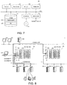
- FIG. 7 is a schematic diagram showing a hardware configuration example of the support apparatus 400 connected to the control apparatus 2 of this embodiment.
- the support apparatus 400 is achieved by using hardware in accordance with a general-purpose architecture (for example, a general-purpose PC) to execute the programs.
- a general-purpose architecture for example, a general-purpose PC
- the support apparatus 400 includes a processor 402, a main memory 404, a storage 406, an input part 408, a display part 410, an optical drive 412, and a USB controller 416. These components are connected via a processor bus 418.
- the processor 402 is formed of a CPU and the like, reads out the programs (for example, an OS 4060 and a support program 4062) stored in the storage 406 and develops the programs in the main memory 404 for execution, thereby implementing various processings described later.
- programs for example, an OS 4060 and a support program 4062
- the main memory 404 is formed of a volatile memory apparatus or the like such as a DRAM, a SRAM or the like.
- the storage 406 is formed of, for example, a non-volatile memory apparatus or the like such as a HDD, a SSD or the like.
- the support program 4062 for providing the function as the support apparatus 400 is stored.
- the input part 408 is formed of a keyboard, a mouse or the like and receives user operations.
- the display part 410 is formed of a display, various indicators, a printer and so on and outputs processing results and the like from the processor 402.
- the USB controller 416 controls, via USB connection, the data exchange with the standard control unit 100 and the like of the control apparatus 2.
- the support apparatus 400 has an optical drive 412, and from a recording medium 414 (for example, an optical recording medium such as a DVD (Digital Versatile Disc) or the like) which stores computer-readable programs in a non-transitory manner, the programs stored therein are read out to be installed in the storage 406 and the like.
- a recording medium 414 for example, an optical recording medium such as a DVD (Digital Versatile Disc) or the like
- the support program 4062 and the like executed in the support apparatus 400 may be installed via the computer-readable recording medium 414, or be installed in a form downloaded from the server apparatus and the like on the network. Besides, the functions provided by the support apparatus 400 of this embodiment may also be achieved in a form employing part of the module provided by the OS.
- FIG. 7 the configuration example is shown in which necessary functions as the support apparatus 400 are provided by the processor 402 executing the programs, but dedicated hardware circuits (for example, ASIC, FPGA or the like) may be used to implement part or all of the functions that are provided.
- dedicated hardware circuits for example, ASIC, FPGA or the like
- the HMI 500 may employ a hardware configuration mounted as a dedicated machine or employ a hardware configuration in accordance with a general-purpose architecture (for example, an industrial PC based on a general-purpose PC).
- a general-purpose architecture for example, an industrial PC based on a general-purpose PC.
- the hardware configuration similar to the support apparatus 400 as shown in the aforementioned FIG. 7 is employed.
- an application program for achieving HMI processing is installed instead of the support program 4062 in the configuration example shown in FIG. 7 .
- the server apparatus 600 can be achieved using a general-purpose file server or database server.
- the hardware configuration of such an apparatus is publicly known, and thus more detailed description is not performed.
- FIG. 8 is a schematic diagram for describing the communication method of the safety control system 1 of this embodiment.
- both the communication between the control apparatus 2 and the remote device 300 and the communication between control apparatuses 2 employ one kind of message transmission.
- connection #1 is established between the control apparatus 2A and the remote device 300-1
- a connection #2 is established between the control apparatus 2A and the remote device 300-2
- a connection #3 is established between the control apparatus 2A and the remote device 300-3
- a connection #4 is established between the control apparatus 2A and the control apparatus 2B.
- the side which functions as a communication master is also referred to as an "originator” and the side which functions as a communication slave is also referred to as a "target”.
- a data size of the data exchanged in each connection (also referred to as "data set” hereinafter) is set for the originator and the target in advance. For example, input-output data up to the predetermined data size can be allocated to one data set (that is, each connection).
- the input-output data is allocated to each data set at a predetermined data unit (also referred to as "the IO assembly” hereinafter).
- the IO assembly means variables or objects accessible from outside.
- Tag names are set in advance as identification information for specifying each datum.
- the tag name can also be regarded as a name of the object indicating each datum.
- Corresponding data can be specified by designating the tag names.
- the IO assembly may include an input assembly indicating data (input data) which is generated or collected in the target and given to the originator, and an output assembly indicating data (output data) which is generated or collected in the originator and given to the target. Furthermore, the IO assembly may include a safety input assembly consisting of input data related to function safety and a safety output assembly consisting of output data related to function safety. In the description below, unless otherwise described, the term of "the IO assembly" is used in the meaning of including at least any one of the input assembly, the output assembly, the safety input assembly, and the safety output assembly.
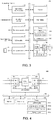
- FIG. 9A and FIG. 9B are schematic diagrams showing an example of the IO assembly in the remote device 300 of the safety control system 1 of this embodiment.
- FIG. 10 is a schematic diagram showing an example of the IO assembly in the control apparatus 2 (the safety control unit 200) of the safety control system 1 of this embodiment.
- IO assemblies 340 of a predetermined data size or number is prepared depending on the function and the like of the remote device 300.
- the data size or number of the IO assemblies 340 is predetermined corresponding to the function or the number of input-output points of the IO module 308 mounted in the remote device 300.
- the IO assemblies 340 prepared in the remote device 300 is accessible from the control apparatus 2 (the safety control unit 200) which functions as the originator.
- IO assemblies 340 (the IO assemblies #1-#4) are prepared in the remote device 300.
- Tag names 341 are set in advance for each of the four IO assemblies 340.
- all of the four IO assemblies 340 (the IO assemblies #1-#4) are allocated to the data set.
- two of the four IO assemblies 340 (the IO assemblies #1 and #2) are allocated to the data set.
- the allocation of the IO assemblies 340 allocated to the data set among the IO assemblies 340 is set for each remote device 300 by the support apparatus 400.
- the data size (number) of the IO assemblies 340 stored in the data set can be changed optionally in a predetermined limitation range.
- the control apparatus 2 may functions as the target.
- the example shown in FIG. 8 corresponds to a case in which the control apparatus 2A becomes the originator and the control apparatus 2B becomes the target (the connection #4).
- the remote device 300 is predetermined to provide specific functions, basically, the data size (number) and classification (for example, distinction between input-output purpose, input purpose, and output purpose) of the IO assemblies 340 are predetermined.
- the control apparatus 2 a plurality of input-output data and internal variables can be employed, and it is impossible to disclose all these data as the IO assemblies. Therefore, the data to be disclosed as the IO assemblies is also set corresponding to the application.
- the processor 202 executes the system program 2060 and the safety program 2066 ( FIG. 4 ), and thereby a control operation 242 is implemented. Along with the implementation of the control operation 242, values of internal data groups 244 are also updated sequentially.
- Predetermined data in the internal data groups 244 is allocated to IO assemblies 240.
- the specific data contained in the internal data groups 244 are allocated as four IO assemblies 240 (the IO assemblies #1-#4).
- Tag names 241 are set in advance for each of the four IO assemblies 240.
- one or a plurality of pre-designated IO assemblies 240 are allocated to the data set. That is, as shown in the aforementioned FIG. 9A , all of the four IO assemblies 240 may be allocated to one data set, or only part of the four IO assemblies 240 is allocated to one data set.
- the correspondence of the internal data group 244 to the IO assemblies 240 in the control apparatus 2 and selection of the IO assemblies 240 allocated to the data set in the control apparatus 2 are implemented by the support apparatus 400.
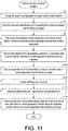
- FIG. 11 is a flowchart showing a procedure example of the setting and user program creation in the safety control system 1 of this embodiment. Each step shown in FIG. 11 is basically implemented by the processor 402 of the support apparatus 400 executing the support program 4062.
- step S2 the user designates a system configuration of the target safety control system 1 (step S2).
- step S4 the user sets the data size and the classification of the IO assembly for the control apparatus 2 (the safety control unit 200) that functions as the target (step S4).
- the processing shown in step S4 corresponds to the operation of designating the data disclosed from the control apparatus 2 that functions as the target. Therefore, the processing of step S4 can be skipped when the control apparatus 2 that functions as the target does not exist (or there is no data required to be disclosed).
- the user sets the connection between the control apparatus 2 and the remote device 300 and/or the connection between the control apparatus 2 and another control apparatus 2 (step S6). That is, the support apparatus 400 receives the connection setting which is the setting of the connection established between the control apparatus 2 and each remote device 300 (corresponding to the setting reception function).
- the user sets the correspondence of the IO assemblies contained in the connection that is set to the internal variables in the control apparatus 2 that functions as the originator (step S8). That is, the support apparatus 400 receives the setting of the variable names used for reference in the program executed in the control apparatus 2 for each datum exchanged in the connection that is set (corresponding to the setting reception function). At this time, the correspondence of the input-output data managed by the local IO unit 250 which is an example of the local device to the internal variables may also be set in parallel.
- step S10 when the control apparatus 2 that functions as the target exists, the correspondence of the IO assemblies to the internal variables is also set in the control apparatus 2 that functions as the target (step S10).
- step S12 When the aforementioned setting procedures are finished, the user creates an arbitrary user program (step S12).
- the user program created at this time may contain a code for referring to the internal variables set in step S10.
- the support apparatus 400 After the creation of the user program, the support apparatus 400 generates set data and the user program of execution form (step S14).
- the tag names to be contained in the connection setting are determined based on the correspondence of the IO assemblies to the internal variables set in step S10. That is, the support apparatus 400 determines the tag name associated with each datum based on the variable name set for each datum, and generates the connection setting that contains each tag name that is determined (corresponding to the generation function).
- the tag name set for each IO assembly may be the same as the internal variables (each variable name) set by the user, or a character string generated from each variable name by a predetermined rule may be used.
- the support apparatus 400 transmits a data form that contains the setting data and the user program of the execution form to the control apparatus 2 that functions as the originator, the remote device 300, and the control apparatus 2 that functions as the target (step S16). In this way, the support apparatus 400 transmits the connection setting received in step S2 to the control apparatus 2 and the remote device 300 involved in the connection setting (corresponding to the transmission function).
- connection setting The setting procedures of the connection setting are finished by a series of processings as mentioned above.
- FIG. 12-FIG. 18 The user interface screens shown in FIG. 12-FIG. 18 are typically presented to the user via the display part 410 of the support apparatus 400.
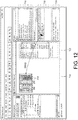
- FIG. 12 is a schematic diagram shown an example of a user interface screen 700 related to the designation of the system configuration (step S2) shown in FIG. 11 .
- the user interface screen 700 includes a system configuration field 710 that visualizes the system configuration in the creation.
- the user defines the device (hardware) included in the target safety control system 1 by a keyboard, a mouse or the like.
- the user interface screen 700 includes a device classification list box 716 and a device list box 718 as toolboxes on the right side of the screen.
- the user first selects the classification of the device to be included in the system configuration in the device classification list box 716.
- the device list box 718 one or a plurality of devices that belongs to the classification selected in the device classification list box 716 is displayed by a list.
- the user selects the desired device from the list and drags the desired device to the system configuration field 710. Accordingly, the selected device is added.
- the user interface screen 700 includes a model information text box 720 that indicates model information and the like of the selected device, and an attribute text box 722 that indicates attributes of the selected device.
- the user adds the device while confirming the content displayed in the model information text box 720.
- the attributes of the added device can be changed in the attribute text box 722.
- the user repeats the aforementioned procedures until all the devices included in the system configuration are added.
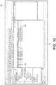
- FIG. 13 is a schematic diagram showing an example of the user interface screen 701 related to the setting of the data size and the classification of the IO assemblies (step S4) shown in FIG. 11 .
- the user interface screen 701 includes an IO assembly visualization area 724 that visualizes the IO assemblies that are allocated.
- the user defines the device (hardware) included in the target safety control system 1 by the keyboard, the mouse or the like. More specifically, in the user interface screen 701, an IO assembly list 728 indicating a series of IO assemblies that can be set to the target control apparatus 2 (the safety control unit 200) is displayed, and the user validates the setting of the IO assemblies displayed in the IO assembly list 728 by checking a checkbox 726.
- the IO assembly list 728 includes two input assemblies consisting of 16 bytes, an input assembly consisting of 8 bytes, and an output assembly consisting of 8 bytes.
- the data size and the classification of the IO assemblies displayed in the checkbox 726 may be different corresponding to the model and the like of the control apparatus 2 that is set. Besides, among one or a plurality of the IO assemblies displayed in the checkbox 726 as default, the checkbox 726 corresponding to the predetermined IO assembly may be checked.
- FIG. 14 and FIG. 15 are schematic diagrams shown an example of a user interface screen 702 related to the setting of the connection (step S6) shown in FIG. 11 .
- the user interface screen 702 includes a connection visualization area 730 that visualizes the connection that is set.
- connection visualization area 730 a connection setting 732 with a unit having "192.168.1.2" as an IP address is displayed. Moreover, the IP address of the originator is set to "192.168.1.1".
- the connection setting 732 defines the connection with another control apparatus 2 (the safety control unit 200) and includes an input-output assembly setting 734.
- the input-output assembly setting 734 it is defined that an input assembly consisting of 16 bytes is exchanged.
- the user interface screen 702 includes a target classification list box 742 and a target list box 744 as the toolboxes on the right side of the screen.
- the user first selects the classification of the unit to be set as the target of the connection to be set in the target classification list box 742.
- the target list box 744 one or a plurality of units that belongs to the classification selected in the target classification list box 742 is displayed by a list.
- the user interface screen 702 includes a model information text box 746 that indicates model information and the like of the selected unit. The user adds the device while confirming the content displayed in the model information text box 746.
- connection visualization area 730 when the user drags any unit (target) to the connection visualization area 730, the connection to the selected unit is added.
- the user interface screen 702 displays the remote devices 300 capable of establishing connection from the control apparatus 2 in a list, and receives the selection to the remote devices 300 that are displayed in a list.
- a connection setting 736 with the selected unit (in this example, the unit having "192.168.1.3" as the IP address) is automatically generated.
- the support apparatus 400 temporarily allocates the input-output data predetermined for the selected remote device 300 to the selected remote device 300.
- the user interface screen 702 receives an alteration operation from the user to the input-output data that is temporarily allocated. For example, by the operation to the checkbox corresponding to the setting of each input-output datum, validation/invalidation of the input-output data that is temporarily allocated can be switched.
- connection setting 736 defines the connection with the remote device 300 and includes the designation of the input-output data exchanged between the target control apparatus 2 and the remote device 300.
- the connection setting 736 includes input-output assembly settings 738 and 740 as the designation of the input-output data.
- an input assembly (safety input) consisting of 2 bytes is exchanged
- an output assembly (safety output) consisting of 1 byte is exchanged.
- the designation of the input-output data included in the connection setting 736 includes the setting of the size (for example, 1 byte, 2 bytes or the like) of the data that is exchanged.
- the designation of the input-output data included in the connection setting 736 also includes the setting of the classification (for example, input data, output data, safety input, safety output) of the data that is exchanged. That is, the classification of the data indicates whether the data that is exchanged is the input data transmitted from the target remote device 300 to the control apparatus 2 or the output data transmitted from the control apparatus 2 to the target remote device 300.
- the classification of the data indicates whether the data that is exchanged is the input data transmitted from the target remote device 300 to the control apparatus 2 or the output data transmitted from the control apparatus 2 to the target remote device 300.
- the number and the classification of the input-output assembly settings 738 and 740 are automatically determined corresponding to the classification and/or the model of the unit (target) added by the user.
- the input assembly (safety input) consisting of 2 bytes and the output assembly (safety output) consisting of 1 byte are automatically set corresponding to the classification and/or the model of the selected unit (target), but when another unit (target) is added, the IO assembly with a different data size and classification may be designated corresponding to the classification and/or the model of the unit that is added.
- the processing of automatically designating such an IO assembly is described later in detail.
- the user repeats the aforementioned procedures until all the connections required by the system configuration are defined.
- the selected remote device 300 and the content (the input-output assembly settings 738 and 740) of the input-output data temporarily allocated to the selected remote device 300 are associated visualized.
- FIG. 16 and FIG. 17 are schematic diagrams showing an example of a user interface screen 703 related to the correspondence of the IO assemblies contained in the connection that is set to the internal variables (step S8) shown in FIG. 11 .
- the user interface screen 703 provides a function of IO mapping to perform the correspondence of the input-output data available in the control apparatus 2 (the standard control unit 100 and/or the safety control unit 200) to the internal variables.
- the user interface screen 703 includes an IO map visualization area 750 that visualizes the correspondence of the input-output data and the IO assembly to the internal variables.
- the IO map visualization area 750 includes a local IO data column 752 and a remote IO data column 754.
- the input-output data provided by the local IO unit 250 that is connected to the standard control unit 100 and/or the safety control unit 200 via the local bus 12 is hierarchically displayed by a list.
- FIG. 16 and FIG. 17 the example (see FIG. 12 ) in which the standard control unit 100 that functions as the master controller of the local bus 12 is connected to two local IO units 250 is shown.
- the IO assemblies provided by the remote device 300 and/or another control apparatus 2 (the standard control unit 100 and/or the safety control unit 200) which is connected via the field network 4 and/or the superordinate network 6 are shown. That is, in the remote IO data column 754, the IO assemblies provided by the target which is accessible for the control apparatus 2 (the standard control unit 100 and/or the safety control unit 200) as the originator is shown.
- the remote IO data column 754 includes a safety control unit item 756 which indicates the IO assemblies provided by another control apparatus 2 (the safety control unit 200), and a remote device item 758 which indicates the IO assemblies provided by the remote device 300.
- a unit item 760 indicating the safety IO unit that is one of the local IO units 250 is developed to a lower layer. That is, an IO map 768 is displayed in association with the unit item 760. In the IO map 768, a plurality of columns is defined in association with each input port included by the target safety IO unit.
- port information 761 indicating a target signal
- R/W information 762 indicating whether the target signal is read-only or writable
- data classification information 763 indicating the data classification of the target signal
- variable information 764 indicating the variable name allocated to the target signal
- comment 765 including arbitrary information related to the target signal
- variable type information 766 indicating a variable type of a target variable
- the user can allocate an arbitrary internal variable available in the user program to each input-output datum via the user interface screen 703. As described later, by designating the internal variables defined in the user interface screen 703 in the user program that is created, during the execution, actual values (instance) of the input-output data that is designated can be used.
- an example is shown in which the safety control unit item 756 indicting another safety control unit 200 is developed to lower layers. That is, an IO map 778 is displayed in association with the safety control unit item 756. In the IO map 778, a plurality of columns is defined in association with the IO assembly provided by the target safety control unit 200.
- port information 771 indicating each element of the target IO assembly
- R/W information 772 indicating whether the target element is read-only or writable
- data classification information 773 indicating the data classification of the target element
- variable information 774 indicating the variable name allocated to the target element
- comment 775 including arbitrary information related to the target element
- variable type information 776 indicating the variable type related to the target element
- the data classification information 773 the data classification (boolean value for safety control, digit value for safety control, boolean value for standard control, digit value for standard control and so on) is set.
- variable type information 776 the data attribute of the variable (global variable, local variable and so on) is set.
- the user can allocate an arbitrary internal variable available in the user program to each element of the IO assembly via the user interface screen 703. As described later, by designating the internal variables defined in the user interface screen 703 in the user program that is created, during the execution, actual values (instance) of the IO assembly that is designated can be used.
- the internal variable (variable name) that is set for each element of the IO assembly is employed in the connection setting to generate the tag name that is set for each element of the IO assembly.
- the support apparatus 400 receives the setting of the variable names used for reference in the program executed in the control apparatus 2 for the input-output data managed by the local IO unit 250 that is an example of the local device.
- the support apparatus 400 receives the setting of the variable names used for reference in the program executed in the control apparatus 2 for each datum (the IO assembly) exchanged in the connection that is set. In this way, the setting of the variable names to the input-output data managed by the local IO unit 250 and the setting of the variable names to each datum (the IO assembly) exchanged in the connection that is set can be performed in the same screen.
- the setting items in each setting are in common.
- the allocation of variables to the input-output data provided by the local IO unit 250 and to the IO assembly provided by the remote device 300 and/or the control apparatus 2 can be substantially performed in the same aspect.
- FIG. 18 is a schematic diagram showing an example of a user interface screen 704 related to the creation of an arbitrary user program (step S12) shown in FIG. 11 .
- the user interface screen 704 includes a program visualization area 780 that visualizes the user program being edited. The user creates the arbitrary user program by the keyboard, the mouse or the like.
- the user interface screen 704 includes a component list box 782 as the toolbox on the right side of the screen.
- the user selects in the component list box 782 the component to be used in the user program and drags the component to the program visualization area 780. Then, the selected component is arranged on the dragged position or associated with an existing component. The user repeats the operation of component arrangement until the desired user program is finished.
- an example is shown in which an emergency stop function block 784 is arranged and the internal variable "CIP Originator-Instance2-Byte1-bit0" allocated to the element of the IO assembly in the user interface screen 703 shown in FIG. 17 is designate as the safety input signal of the emergency stop function block 784.
- the user creates the arbitrary user program by the operation procedures as shown in FIG. 18 .
- a build processing (a type of compiling processing) is implemented and the program having the setting information or execution form that is generated is transmitted to the target unit.
- the setting and the processing of program transmission can employ an arbitrary user interface screen and detailed description is not performed herein.
- the user interface screen 702 when the user drags the target unit to the connection visualization area 730, the target of connection object is added and the IO assembly allocated to the connection with the added target is automatically determined.
- Such a processing of automatically determining the IO assembly is implemented by referring to a predetermined IO assembly setting table and the like in the support apparatus 400.
- FIG. 19 is a schematic diagram showing an example of an IO assembly setting table 800 referred to by the support apparatus 400 of the safety control system 1 of this embodiment.
- the IO assembly setting table 800 includes a type field 802 indicating the classification and/or model of the target, an IO field 804 indicating the classification of the IO assembly to be added, and a byte field 806 indicating the data size of each IO assembly.
- the support apparatus 400 refers to the type field 802 of the IO assembly setting table 800 and extracts the classification and/or model corresponding to the classification of the added target. Then, the classification (the IO field 804) and the data size (the byte field 806) of the IO assembly corresponding to the extracted classification and/or model are extracted and determined as the IO assembly of the added target. Then, the support apparatus 400 displays the determined IO assembly in the connection visualization area 730.
- the support apparatus 400 can automatically add the IO assembly corresponding to the target to which the connection is set by referring to the IO assembly setting table 800. Accordingly, registration and the like of the IO assembly required for the connection setting can be easily performed even by the user lacking knowledge.
- control apparatus 2 and the support apparatus 400 are mutually independent configurations, but all or part of the functions of the support apparatus 400 may be incorporated into the control apparatus 2.
- the processing such as the aforementioned connection setting and so on can be implemented more easily.
- control apparatus 2 in which the standard control unit 100 and the safety control unit 200 are combined is mainly illustrated.
- the present invention is not limited hereto and it is evident that the technical ideas of the invention of this application are also applicable to the control apparatus in which a plurality of standard control units 100 is combined and the control apparatus in which a plurality of safety control units 200 is combined.
- the present invention is not limited to the standard control unit and the safety control unit and may be the combination of arbitrary control units.
- a support apparatus (400) that is directed to a control apparatus (2) network-connected with one or a plurality of remote devices (300) and includes: a first setting reception part, which receives a setting of connection established between the control apparatus and any remote device (S6); a second setting reception part, which receives a setting of a variable name used for reference in a program executed in the control apparatus for each datum exchanged in the connection that is set (S10); a generation part, which determines a tag name associated with each datum based on the variable name that is set for each datum, and generates a connection setting that contains each tag name that is determined (S14); and a transmission part, which transmits the connection setting that is generated to the control apparatus and the device which are involved in the connection setting (S16).
- the support apparatus further including a third setting reception part which receives a setting of variable names used for reference in the program executed in the control apparatus for input-output data managed by a local device (S8), wherein the reception of setting by the second setting reception part and the reception of setting by the third setting reception part can be performed in the same screen.
- a support program (4062) that is executed in a computer (400) capable of communicating with a control apparatus (2) network-connected to one or a plurality of remote devices (300), the support program making the computer execute: a step (S6) to receive a setting of connection established between the control apparatus and any remote device; a step (S10) to receive a setting of a variable name used for reference in a program executed in the control apparatus for each datum exchanged in the connection that is set; a step (S14) to determine a tag name associated with each datum based on the variable name that is set for each datum and to generate a connection setting that contains each tag name that is determined; and a step (S16) to transmit the connection setting that is generated to the control apparatus and the device which are involved in the connection setting.
- a setting method for a control system (1) which includes a control apparatus (2) and one or a plurality of remote devices (300) network-connected to the control apparatus, including: a step (S6) to receive a setting of connection established between the control apparatus and any remote device; a step (S10) to receive a setting of a variable name used for reference in a program executed in the control apparatus for each datum exchanged in the connection that is set; a step (S14) to determine a tag name associated with each datum based on the variable name that is set for each datum and to generate a connection setting that contains each tag name that is determined; and a step (S16) to transmit the connection setting that is generated to the control apparatus and the device which are involved in the connection setting.
- the connection setting between the control apparatus 2 and the remote device 300 can be facilitated.
Landscapes
- Engineering & Computer Science (AREA)
- Computer Networks & Wireless Communication (AREA)
- Signal Processing (AREA)
- General Engineering & Computer Science (AREA)
- Manufacturing & Machinery (AREA)
- Quality & Reliability (AREA)
- Physics & Mathematics (AREA)
- General Physics & Mathematics (AREA)
- Automation & Control Theory (AREA)
- Programmable Controllers (AREA)
- Computer And Data Communications (AREA)
Applications Claiming Priority (1)
| Application Number | Priority Date | Filing Date | Title |
|---|---|---|---|
| JP2018069452A JP2019179476A (ja) | 2018-03-30 | 2018-03-30 | サポート装置、サポートプログラム、設定方法 |
Publications (1)
| Publication Number | Publication Date |
|---|---|
| EP3564767A1 true EP3564767A1 (de) | 2019-11-06 |
Family
ID=65529246
Family Applications (1)
| Application Number | Title | Priority Date | Filing Date |
|---|---|---|---|
| EP19156684.3A Withdrawn EP3564767A1 (de) | 2018-03-30 | 2019-02-12 | Unterstützungsvorrichtung, unterstützungsprogramm und einstellverfahren |
Country Status (4)
| Country | Link |
|---|---|
| US (1) | US20190306250A1 (de) |
| EP (1) | EP3564767A1 (de) |
| JP (1) | JP2019179476A (de) |
| CN (1) | CN110324220A (de) |
Families Citing this family (5)
| Publication number | Priority date | Publication date | Assignee | Title |
|---|---|---|---|---|
| JP7375360B2 (ja) * | 2019-08-02 | 2023-11-08 | オムロン株式会社 | ネットワークシステム、情報処理装置、および情報処理方法 |
| JP7379948B2 (ja) * | 2019-08-30 | 2023-11-15 | オムロン株式会社 | サポート装置、サポートプログラムおよび設定方法 |
| JP7571406B2 (ja) * | 2020-07-22 | 2024-10-23 | オムロン株式会社 | 制御システムおよび制御方法 |
| US11687053B2 (en) * | 2021-03-08 | 2023-06-27 | Saudi Arabian Oil Company | Intelligent safety motor control center (ISMCC) |
| US12615275B2 (en) | 2023-06-21 | 2026-04-28 | Saudi Arabian Oil Company | Method and system for integrated cybersecurity operations |
Citations (3)
| Publication number | Priority date | Publication date | Assignee | Title |
|---|---|---|---|---|
| US6947389B1 (en) * | 2000-06-30 | 2005-09-20 | Fisher-Rosemount Systems, Inc. | Two-mode foundation fieldbus device configurator |
| EP2226693A1 (de) * | 2009-03-05 | 2010-09-08 | Siemens Aktiengesellschaft | Programmiergerät zur Projektierung einer Kommunikationsverbindung zwischen Automatisierungskomponenten in einer industriellen Automatisierungsanordnung |
| US20170262568A1 (en) * | 2016-03-14 | 2017-09-14 | Omron Corporation | Program development support device, non-transitory storage medium storing thereon computer-readable program development support program, and program development support method |
Family Cites Families (22)
| Publication number | Priority date | Publication date | Assignee | Title |
|---|---|---|---|---|
| WO1999021198A1 (fr) * | 1997-10-17 | 1999-04-29 | Jacques Clausin | Dispositif de commande proportionnelle de force delivree par un electro-aimant independante des variations des tensions d'alimentation et des entrefers |
| US7058712B1 (en) * | 2002-06-04 | 2006-06-06 | Rockwell Automation Technologies, Inc. | System and methodology providing flexible and distributed processing in an industrial controller environment |
| JP2006011511A (ja) * | 2004-06-22 | 2006-01-12 | Yokogawa Electric Corp | 複数装置のデータ相互アクセス方法および複数装置を有するシステム |
| US7433741B2 (en) * | 2005-09-30 | 2008-10-07 | Rockwell Automation Technologies, Inc. | Hybrid user interface having base presentation information with variably prominent supplemental information |
| JP2008027156A (ja) * | 2006-07-20 | 2008-02-07 | Omron Corp | シミュレーション装置 |
| JP5318111B2 (ja) * | 2007-10-24 | 2013-10-16 | ラントロニクス・インコーポレイテツド | リモートデバイスに構成情報を自動配布するための中央管理ステーションのための種々の方法および装置 |
| DE102009042354C5 (de) * | 2009-09-23 | 2017-07-13 | Phoenix Contact Gmbh & Co. Kg | Verfahren und Vorrichtung zur sicherheitsgerichteten Kommunikation im Kommunikations-Netzwerk einer Automatisierungs-Anlage |
| CN104821891B (zh) * | 2009-11-23 | 2018-11-30 | 皇家Kpn公司 | 用于远程设备管理的方法和系统 |
| US9182755B2 (en) * | 2010-08-26 | 2015-11-10 | Rockwell Automation Technologies, Inc. | Automated operator interface generation in a control system |
| DE102010048588A1 (de) * | 2010-10-18 | 2012-04-19 | Phoenix Contact Gmbh & Co. Kg | Verfahren und Vorrichtung zur Konfiguration von Netzteilnehmern |
| WO2012114444A1 (ja) * | 2011-02-21 | 2012-08-30 | 三菱電機株式会社 | エンジニアリング装置 |
| US8756041B2 (en) * | 2011-03-07 | 2014-06-17 | Rockwell Automation Technologies, Inc. | Industrial simulation using redirected I/O module configurations |
| US10037443B2 (en) * | 2011-03-07 | 2018-07-31 | Rockwell Automation Technologies, Inc. | Industrial simulation using redirected I/O module configurations |
| JP5942446B2 (ja) * | 2012-02-01 | 2016-06-29 | オムロン株式会社 | サポート装置およびサポートプログラム |
| US9054863B2 (en) * | 2012-09-04 | 2015-06-09 | Rockwell Automation Asia Pacific Business Center Pte. Ltd. | Industrial protocol system authentication and firewall |
| US9230436B2 (en) * | 2013-11-06 | 2016-01-05 | Here Global B.V. | Dynamic location referencing segment aggregation |
| US9645572B2 (en) * | 2013-11-07 | 2017-05-09 | Rockwell Automation Technologies, Inc. | Device class information support for multi-option devices |
| US9632492B2 (en) * | 2015-01-23 | 2017-04-25 | Rockwell Automation Asia Pacific Business Ctr. Pte., Ltd. | Redundant watchdog method and system utilizing safety partner controller |
| US9923993B2 (en) * | 2015-11-02 | 2018-03-20 | Rockwell Automation Technologies, Inc. | Self-describing diagnostic data for presentation on mobile devices |
| US10387392B2 (en) * | 2016-05-17 | 2019-08-20 | Rockwell Automation Technologies, Inc. | Method to automate historian configuration using controller based tag meta attribute |
| US10764255B2 (en) * | 2016-09-21 | 2020-09-01 | Rockwell Automation Technologies, Inc. | Secure command execution from a cloud monitoring system to a remote cloud agent |
| US11221606B2 (en) * | 2017-09-26 | 2022-01-11 | Honeywell International Inc. | System and method for depicting and using one logical connection with collection of input/output (I/O) modules as multiple individual logical connections |
-
2018
- 2018-03-30 JP JP2018069452A patent/JP2019179476A/ja active Pending
-
2019
- 2019-02-12 CN CN201910110639.8A patent/CN110324220A/zh active Pending
- 2019-02-12 EP EP19156684.3A patent/EP3564767A1/de not_active Withdrawn
- 2019-02-14 US US16/275,333 patent/US20190306250A1/en not_active Abandoned
Patent Citations (3)
| Publication number | Priority date | Publication date | Assignee | Title |
|---|---|---|---|---|
| US6947389B1 (en) * | 2000-06-30 | 2005-09-20 | Fisher-Rosemount Systems, Inc. | Two-mode foundation fieldbus device configurator |
| EP2226693A1 (de) * | 2009-03-05 | 2010-09-08 | Siemens Aktiengesellschaft | Programmiergerät zur Projektierung einer Kommunikationsverbindung zwischen Automatisierungskomponenten in einer industriellen Automatisierungsanordnung |
| US20170262568A1 (en) * | 2016-03-14 | 2017-09-14 | Omron Corporation | Program development support device, non-transitory storage medium storing thereon computer-readable program development support program, and program development support method |
Non-Patent Citations (1)
| Title |
|---|
| ODVA, THE COMMON INDUSTRIAL PROTOCOL, 15 March 2018 (2018-03-15), Retrieved from the Internet <URL:https://www.odva.org/ Technology-Standards/Common-Industrial-Protocol-CIP/Overview> |
Also Published As
| Publication number | Publication date |
|---|---|
| JP2019179476A (ja) | 2019-10-17 |
| US20190306250A1 (en) | 2019-10-03 |
| CN110324220A (zh) | 2019-10-11 |
Similar Documents
| Publication | Publication Date | Title |
|---|---|---|
| JP7275224B2 (ja) | I/o抽象化フィールドデバイス構成を使用したプロセスプラントの構成のためのシステム及び方法 | |
| US20190306250A1 (en) | Support apparatus, non-transitory computer-readable recording medium and setting method | |
| US11435728B2 (en) | I/O virtualization for commissioning | |
| CN113557478B (zh) | 控制器系统、支持装置及评价方法 | |
| US11165745B2 (en) | Control system, controller, and control method | |
| EP3588215B1 (de) | Steuerungssystem | |
| US20150127120A1 (en) | Device Class Information Support for Multi-Option Devices | |
| EP3564766A1 (de) | Trägervorrichtung, trägerprogramm und einstellverfahren | |
| WO2021065032A1 (ja) | 制御システム、サポート装置およびサポートプログラム | |
| JP2014035687A (ja) | エンジニアリングシステムとその監視制御方法 | |
| US10715396B2 (en) | Support apparatus, non-transitory computer readable recording medium and setting method | |
| JP6135247B2 (ja) | 情報処理装置および情報処理プログラム | |
| US12072681B2 (en) | Support device, non-transitory computer-readable recording medium recording support program, and setting method | |
| US11651006B2 (en) | Method of visualizing screen content on a data visualization system, and data visualization system for visualizing screen content | |
| EP3779614B1 (de) | Sicherheitskontrollsystem und kontrollverfahren in einem sicherheitskontrollsystem | |
| WO2019176286A1 (ja) | 制御装置、制御方法、および、制御プログラム | |
| JP3497423B2 (ja) | 制御用表示装置、制御システム、および、そのプログラムが記録された記録媒体 | |
| JP2019040550A (ja) | 制御プログラム変換装置および方法 | |
| JP2019197449A (ja) | 機器管理装置およびタグ名検証方法 |
Legal Events
| Date | Code | Title | Description |
|---|---|---|---|
| PUAI | Public reference made under article 153(3) epc to a published international application that has entered the european phase |
Free format text: ORIGINAL CODE: 0009012 |
|
| STAA | Information on the status of an ep patent application or granted ep patent |
Free format text: STATUS: REQUEST FOR EXAMINATION WAS MADE |
|
| 17P | Request for examination filed |
Effective date: 20190212 |
|
| AK | Designated contracting states |
Kind code of ref document: A1 Designated state(s): AL AT BE BG CH CY CZ DE DK EE ES FI FR GB GR HR HU IE IS IT LI LT LU LV MC MK MT NL NO PL PT RO RS SE SI SK SM TR |
|
| AX | Request for extension of the european patent |
Extension state: BA ME |
|
| RBV | Designated contracting states (corrected) |
Designated state(s): AL AT BE BG CH CY CZ DE DK EE ES FI FR GB GR HR HU IE IS IT LI LT LU LV MC MK MT NL NO PL PT RO RS SE SI SK SM TR |
|
| STAA | Information on the status of an ep patent application or granted ep patent |
Free format text: STATUS: EXAMINATION IS IN PROGRESS |
|
| 17Q | First examination report despatched |
Effective date: 20210707 |
|
| STAA | Information on the status of an ep patent application or granted ep patent |
Free format text: STATUS: THE APPLICATION IS DEEMED TO BE WITHDRAWN |
|
| 18D | Application deemed to be withdrawn |
Effective date: 20230909 |