EP3565205A1 - Procédé de transmission d'un signal de référence, procédé de détermination d'un bruit de phase, et appareils associés - Google Patents
Procédé de transmission d'un signal de référence, procédé de détermination d'un bruit de phase, et appareils associés Download PDFInfo
- Publication number
- EP3565205A1 EP3565205A1 EP17888540.6A EP17888540A EP3565205A1 EP 3565205 A1 EP3565205 A1 EP 3565205A1 EP 17888540 A EP17888540 A EP 17888540A EP 3565205 A1 EP3565205 A1 EP 3565205A1
- Authority
- EP
- European Patent Office
- Prior art keywords
- ptrs
- dmrs
- mapping relationship
- antenna
- port
- Prior art date
- Legal status (The legal status is an assumption and is not a legal conclusion. Google has not performed a legal analysis and makes no representation as to the accuracy of the status listed.)
- Granted
Links
Images




Classifications
-
- H—ELECTRICITY
- H04—ELECTRIC COMMUNICATION TECHNIQUE
- H04L—TRANSMISSION OF DIGITAL INFORMATION, e.g. TELEGRAPHIC COMMUNICATION
- H04L27/00—Modulated-carrier systems
- H04L27/26—Systems using multi-frequency codes
- H04L27/2601—Multicarrier modulation systems
- H04L27/2602—Signal structure
- H04L27/261—Details of reference signals
-
- H—ELECTRICITY
- H04—ELECTRIC COMMUNICATION TECHNIQUE
- H04B—TRANSMISSION
- H04B7/00—Radio transmission systems, i.e. using radiation field
- H04B7/02—Diversity systems; Multi-antenna system, i.e. transmission or reception using multiple antennas
- H04B7/04—Diversity systems; Multi-antenna system, i.e. transmission or reception using multiple antennas using two or more spaced independent antennas
- H04B7/0413—MIMO systems
- H04B7/0456—Selection of precoding matrices or codebooks, e.g. using matrices antenna weighting
- H04B7/046—Selection of precoding matrices or codebooks, e.g. using matrices antenna weighting taking physical layer constraints into account
- H04B7/0473—Selection of precoding matrices or codebooks, e.g. using matrices antenna weighting taking physical layer constraints into account taking constraints in layer or codeword to antenna mapping into account
-
- H—ELECTRICITY
- H04—ELECTRIC COMMUNICATION TECHNIQUE
- H04B—TRANSMISSION
- H04B7/00—Radio transmission systems, i.e. using radiation field
- H04B7/02—Diversity systems; Multi-antenna system, i.e. transmission or reception using multiple antennas
- H04B7/04—Diversity systems; Multi-antenna system, i.e. transmission or reception using multiple antennas using two or more spaced independent antennas
- H04B7/0413—MIMO systems
- H04B7/0456—Selection of precoding matrices or codebooks, e.g. using matrices antenna weighting
-
- H—ELECTRICITY
- H04—ELECTRIC COMMUNICATION TECHNIQUE
- H04B—TRANSMISSION
- H04B7/00—Radio transmission systems, i.e. using radiation field
- H04B7/02—Diversity systems; Multi-antenna system, i.e. transmission or reception using multiple antennas
- H04B7/04—Diversity systems; Multi-antenna system, i.e. transmission or reception using multiple antennas using two or more spaced independent antennas
- H04B7/0413—MIMO systems
- H04B7/0456—Selection of precoding matrices or codebooks, e.g. using matrices antenna weighting
- H04B7/0478—Special codebook structures directed to feedback optimisation
-
- H—ELECTRICITY
- H04—ELECTRIC COMMUNICATION TECHNIQUE
- H04B—TRANSMISSION
- H04B7/00—Radio transmission systems, i.e. using radiation field
- H04B7/02—Diversity systems; Multi-antenna system, i.e. transmission or reception using multiple antennas
- H04B7/04—Diversity systems; Multi-antenna system, i.e. transmission or reception using multiple antennas using two or more spaced independent antennas
- H04B7/06—Diversity systems; Multi-antenna system, i.e. transmission or reception using multiple antennas using two or more spaced independent antennas at the transmitting station
- H04B7/0686—Hybrid systems, i.e. switching and simultaneous transmission
- H04B7/0691—Hybrid systems, i.e. switching and simultaneous transmission using subgroups of transmit antennas
-
- H—ELECTRICITY
- H04—ELECTRIC COMMUNICATION TECHNIQUE
- H04L—TRANSMISSION OF DIGITAL INFORMATION, e.g. TELEGRAPHIC COMMUNICATION
- H04L25/00—Baseband systems
- H04L25/02—Details ; arrangements for supplying electrical power along data transmission lines
-
- H—ELECTRICITY
- H04—ELECTRIC COMMUNICATION TECHNIQUE
- H04L—TRANSMISSION OF DIGITAL INFORMATION, e.g. TELEGRAPHIC COMMUNICATION
- H04L25/00—Baseband systems
- H04L25/02—Details ; arrangements for supplying electrical power along data transmission lines
- H04L25/0202—Channel estimation
- H04L25/0204—Channel estimation of multiple channels
-
- H—ELECTRICITY
- H04—ELECTRIC COMMUNICATION TECHNIQUE
- H04L—TRANSMISSION OF DIGITAL INFORMATION, e.g. TELEGRAPHIC COMMUNICATION
- H04L25/00—Baseband systems
- H04L25/02—Details ; arrangements for supplying electrical power along data transmission lines
- H04L25/0202—Channel estimation
- H04L25/0224—Channel estimation using sounding signals
-
- H—ELECTRICITY
- H04—ELECTRIC COMMUNICATION TECHNIQUE
- H04L—TRANSMISSION OF DIGITAL INFORMATION, e.g. TELEGRAPHIC COMMUNICATION
- H04L27/00—Modulated-carrier systems
- H04L27/26—Systems using multi-frequency codes
-
- H—ELECTRICITY
- H04—ELECTRIC COMMUNICATION TECHNIQUE
- H04L—TRANSMISSION OF DIGITAL INFORMATION, e.g. TELEGRAPHIC COMMUNICATION
- H04L27/00—Modulated-carrier systems
- H04L27/26—Systems using multi-frequency codes
- H04L27/2601—Multicarrier modulation systems
- H04L27/2602—Signal structure
-
- H—ELECTRICITY
- H04—ELECTRIC COMMUNICATION TECHNIQUE
- H04L—TRANSMISSION OF DIGITAL INFORMATION, e.g. TELEGRAPHIC COMMUNICATION
- H04L27/00—Modulated-carrier systems
- H04L27/26—Systems using multi-frequency codes
- H04L27/2601—Multicarrier modulation systems
- H04L27/2647—Arrangements specific to the receiver only
- H04L27/2655—Synchronisation arrangements
- H04L27/2657—Carrier synchronisation
- H04L27/266—Fine or fractional frequency offset determination and synchronisation
-
- H—ELECTRICITY
- H04—ELECTRIC COMMUNICATION TECHNIQUE
- H04L—TRANSMISSION OF DIGITAL INFORMATION, e.g. TELEGRAPHIC COMMUNICATION
- H04L27/00—Modulated-carrier systems
- H04L27/26—Systems using multi-frequency codes
- H04L27/2601—Multicarrier modulation systems
- H04L27/2647—Arrangements specific to the receiver only
- H04L27/2655—Synchronisation arrangements
- H04L27/2668—Details of algorithms
- H04L27/2673—Details of algorithms characterised by synchronisation parameters
- H04L27/2675—Pilot or known symbols
-
- H—ELECTRICITY
- H04—ELECTRIC COMMUNICATION TECHNIQUE
- H04L—TRANSMISSION OF DIGITAL INFORMATION, e.g. TELEGRAPHIC COMMUNICATION
- H04L5/00—Arrangements affording multiple use of the transmission path
- H04L5/0001—Arrangements for dividing the transmission path
- H04L5/0014—Three-dimensional division
- H04L5/0023—Time-frequency-space
-
- H—ELECTRICITY
- H04—ELECTRIC COMMUNICATION TECHNIQUE
- H04L—TRANSMISSION OF DIGITAL INFORMATION, e.g. TELEGRAPHIC COMMUNICATION
- H04L5/00—Arrangements affording multiple use of the transmission path
- H04L5/003—Arrangements for allocating sub-channels of the transmission path
- H04L5/0048—Allocation of pilot signals, i.e. of signals known to the receiver
-
- H—ELECTRICITY
- H04—ELECTRIC COMMUNICATION TECHNIQUE
- H04L—TRANSMISSION OF DIGITAL INFORMATION, e.g. TELEGRAPHIC COMMUNICATION
- H04L5/00—Arrangements affording multiple use of the transmission path
- H04L5/003—Arrangements for allocating sub-channels of the transmission path
- H04L5/0048—Allocation of pilot signals, i.e. of signals known to the receiver
- H04L5/0051—Allocation of pilot signals, i.e. of signals known to the receiver of dedicated pilots, i.e. pilots destined for a single user or terminal
Definitions
- the present invention relates to the field of wireless communications, and particularly to a method and apparatus for transmitting a reference signal, and a method and apparatus for determining phase noise.
- Phase noise is a major noise that causes interference to a communication system in wireless communication
- the phase noise comes from oscillators in a transmitter and a receiver of the communication system, and may seriously affect transmission of a multi-carrier signal, so in order to reduce the influence of phase noise on the multi-carrier signal transmission, phase noise compensation can be performed on a received signal at the receiver to thereby guarantee accuracy of transmission.
- phase-tracking reference signal is introduced at the transmitter, which tracks a phase change arising from phase noise using the phase-tracking reference signal, and then the receiver performs phase noise compensation on the received signal according to the phase change.
- a multi-carrier signal transmission can include the uplink transmission and downlink transmission, and when in the downlink transmission, as illustrated in Fig.1a , 61 and 60 at the top-right corner represent different port serial numbers, where ports of a phase-tracking reference signal occupy a sub-carrier, and each phase-tracking reference signal is transmitted consecutively in a sub-frame; and the transmitter (e.g., a base station) can notify via dynamic downlink signaling the receiver (e.g., a user equipment) of the number of ports for the currently transmitted phase-tracking reference signal, e.g., two ports for transmitting the phase-tracking reference signal, or one port for transmitting the phase-tracking reference signal.
- the receiver e.g., a user equipment
- the transmitter e.g., a base station
- phase-tracking reference signal is used when the transmitter transmits user data to the receiver, and can be transmitted only after being pre-coded.
- the phase-tracking reference signal passes through the same channel as the user data and a corresponding Demodulation Reference Signal (DMRS).
- DMRS Demodulation Reference Signal
- the phase-tracking reference signal is used for calculating a phase difference between channel estimation on a symbol including the phase-tracking reference signal, and channel estimation on a symbol including the DMRS, to thereby determine a phase change arising from phase noise for channel estimation compensation and data demodulation.
- a transmitter in a multi-antenna transmitting and receiving system, includes a plurality of antenna elements or antenna ports. If these antenna elements or antenna ports have same phase noise (phase noise from the same phase noise source), then phase noise may be estimated and compensated correctly in the solution above. However if the antenna elements or the antenna ports in the transmitter have different phase noises, then there may be a plurality of phase changes over channels through which user data pass, and the different phase changes arising from the respective phase noises cannot be estimated in the solution above, so that channel estimation compensation and data demodulation cannot be performed correctly.
- Embodiments of the invention provide a method and apparatus for transmitting a reference signal, and a method and apparatus for determining phase noise, so as to address the problem in the prior art that different phase noises of different antenna elements or antenna ports of a transmitter cannot be estimated and compensated accurately.
- an embodiment of the invention provides a method for transmitting a reference signal, the method including:
- the transmitter pre-codes a data stream in such a way that weights for antenna elements or antenna ports in the other antenna groups than an antenna group corresponding to the data stream are zero; the transmitter pre-codes a DMRS in such a way that weights for antenna elements or antenna ports in the other antenna groups than an antenna group corresponding to the DMRS are zero; and the transmitter pre-codes a PTRS in such a way that weights for antenna elements or antenna ports in the other antenna groups than an antenna group corresponding to the PTRS are zero.
- the method further includes: determining, by the transmitter, a first mapping relationship between the respective PTRS ports and the respective DMRS ports, wherein in the first mapping relationship, one PTRS port is mapped to at least one DMRS port, and the PTRS port and its mapped DMRS port use a same antenna group for transmission.
- the method further includes:
- Optionally transmitting, by the transmitter, the first mapping relationship to the receiver includes:
- the method further includes: determining, by the transmitter, a second mapping relationship between the respective data streams to be transmitted and the respective DMRS ports, wherein in the second mapping relationship, one data stream is mapped to one DMRS port, and the data stream and its mapped DMRS port correspond to a same antenna group for transmission.
- the method further includes:
- Optionally transmitting, by the transmitter, the second mapping relationship to the receiver includes:
- precoder used by the transmitter for a PTRS is the same as or related to precoder used by a data stream over a sub-carrier occupied by the PTRS, the data stream corresponds to a DMRS port corresponding to the PTRS.
- precoder used by the transmitter for a DMRS is the same as or related to precoder used by a data stream over a sub-carrier occupied by the DMRS port, said data stream corresponds to the DMRS port.
- an embodiment of the invention provides a method for determining phase noise, the method including:
- the first mapping relationship is obtained by the receiver as notified by the transmitter, or the first mapping relationship is pre-agreed between the receiver and the transmitter.
- the method further includes:
- the second mapping relationship is obtained by the receiver as notified by the transmitter, or the second mapping relationship is pre-agreed between the receiver and the transmitter.
- an embodiment of the invention provides an apparatus for transmitting a reference signal, the apparatus including:
- the apparatus further includes a pre-coding unit configured:
- the apparatus further includes a first processing unit configured: to determine a first mapping relationship between the respective PTRS ports and the respective DMRS ports, wherein in the first mapping relationship, one PTRS port is mapped to at least one DMRS port, and the PTRS port and its mapped DMRS port use a same antenna group for transmission.
- a first processing unit configured: to determine a first mapping relationship between the respective PTRS ports and the respective DMRS ports, wherein in the first mapping relationship, one PTRS port is mapped to at least one DMRS port, and the PTRS port and its mapped DMRS port use a same antenna group for transmission.
- the first processing unit is further configured:
- the first processing unit configured to transmit the first mapping relationship to the receiver is configured:
- the apparatus further includes a second processing unit configured: to determine a second mapping relationship between the respective data streams to be transmitted and the respective DMRS ports, wherein in the second mapping relationship, one data stream is mapped to one DMRS port, and the data stream and its mapped DMRS port correspond to a same antenna group for transmission.
- a second processing unit configured: to determine a second mapping relationship between the respective data streams to be transmitted and the respective DMRS ports, wherein in the second mapping relationship, one data stream is mapped to one DMRS port, and the data stream and its mapped DMRS port correspond to a same antenna group for transmission.
- the second processing unit is configured:
- the second processing unit configured to transmit the second mapping relationship to the receiver is configured:
- precoder used by the apparatus for a PTRS is the same as or related to precoder used by a data stream over a sub-carrier occupied by the PTRS, the data stream corresponds to a DMRS port corresponding to the PTRS.
- precoder used by the apparatus for a DMRS is the same as or related to precoder used by a data stream over a sub-carrier occupied by the DMRS port, the data stream corresponds to the DMRS port.
- an embodiment of the invention provides an apparatus for determining phase noise, the apparatus including:
- the first mapping relationship is obtained by the apparatus as notified by the transmitter, or the first mapping relationship is pre-agreed between the apparatus and the transmitter.
- the apparatus further includes a fifth processing unit configured:
- the second mapping relationship is obtained by the processor as notified by the transmitter, or the second mapping relationship is pre-agreed between the processors and the transmitter.
- an embodiment of the invention provides an apparatus including a processor, a transceiver, and a memory, wherein the processor is configured to read and execute program in the memory to perform the method according to any one of the solutions in the first aspect.
- an embodiment of the invention provides an apparatus including a processor, a transceiver, and a memory, wherein the processor is configured to read and execute program in the memory to perform the method according to any one of the solutions in the second aspect.
- an embodiment of the invention provides a computer storage medium storing computer executable instructions configured to cause the computer to perform the method according to any one of the solutions in the first aspect.
- an embodiment of the invention provides a computer storage medium storing computer executable instructions configured to cause the computer to perform the method according to any one of the solutions in the second aspect.
- the transmitter transmits respective pre-coded user data streams respectively over their corresponding antenna groups with the same phase noise to the receiver, transmits respective pre-coded DMRSs respectively over their corresponding antenna groups with the same phase noise to the receiver, and transmits respective pre-coded PTRSs respectively over their corresponding antenna groups with the same phase noise to the receiver, where there is the same phase noise for antenna elements or antenna port elements or antenna ports in the same antenna group.
- the receiver Upon reception of the PTRSs, the receiver performs channel estimation based upon the respective received PTRSs, and determines phase changes arising from phase noise corresponding to the different antenna groups, so that even if there is different phase noise of the different antennas of the transmitter, then the receiver will determine the phase changes arising from the different phase noise accurately to thereby compensate for channel estimation results of the DMRS's corresponding to the PTRS's according to the different phase changes, and demodulate all the data transmitted over the different antenna groups accurately according to the different phase changes.
- a transmitter transmits each pre-coded user data stream to a receiver through its corresponding antenna groups with the same phase noise, transmits each pre-coded DMRS to the receiver through its corresponding antenna groups with the same phase noise, and transmits each pre-coded PTRS to the receiver through its corresponding antenna groups with the same phase noise, where antenna elements or antenna port elements or antenna ports in the same antenna group have the same phase noise.
- the receiver Upon reception of the PTRSs, the receiver performs channel estimation based upon each received PTRS, and determines phase changes arising from noise phases corresponding to the different antenna groups.
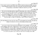
- a detailed flow of a method for determining phase noise according to an embodiment of the invention is as follows.
- a transmitter determines R number of data streams to be transmitted in the current time unit (sub-frame), which are to be transmitted on S number of antenna groups.
- the antennas are grouped into S number of groups according to their phase noise, where the antennas in the same antenna group have the same phase noise.
- an antenna group 1 includes two antennas, which are an antenna 1 and an antenna 2 respectively, and an antenna group 2 includes two antennas, which are an antenna 3 and an antenna 4 respectively, so the antenna 1 and the antenna 2 have the same phase noise, and the antenna 3 and the antenna 4 have the same phase noise.
- each data stream may correspond to one antenna group, or correspond to multiple antenna groups, where all the antenna groups corresponding to one data stream have the same phase noise.
- the data stream 1 and the data stream 2 there are two data streams, which are a data stream 1 and a data stream 2 respectively, and there are three antenna groups, which are an antenna group 1, an antenna group 2, and an antenna group 3 respectively, for example, the data stream 1 corresponds to the antenna group 3, and the data stream 2 corresponds to the antenna group 1 and the antenna group 2, so the antenna group 1 and the antenna group 2 have the same phase noise.
- the transmitter determines R number of Demodulation Reference Signal (DMRS) ports and M number of Phase-Tracking Reference Signal (PTRS) ports.
- DMRS Demodulation Reference Signal
- PTRS Phase-Tracking Reference Signal
- each DMRS port may correspond to one antenna group, or correspond to multiple antenna groups, and all the antenna groups corresponding to one DMRS port have the same phase noise.
- the transmitter determines M number of PTRS ports, where each PTRS port may correspond to one antenna group, or correspond to multiple antenna groups, and all the antenna groups corresponding to one PTRS port have the same phase noise.
- the transmitter determines a first mapping relationship between the M number of PTRS ports and the R number of DMRS ports.
- the transmitter determines a correspondence relationship between each PTRS port and each DMRS port based upon the determined M number of PTRS ports and the determined R number of DMRS ports, where one PTRS port corresponds to at least one DMRS port, and the PTRS port and its corresponding DMRS port(s) use the same antenna group for transmission.
- the DMRS port 1 and the DMRS port 2 correspond to the PTRS port 1, and the DMRS port 3, the DMRS port 4, and the DMRS port 5 correspond to the PTRS port 2, then there is a first mapping relationship between the PTRS port 1, and the DMRS port 1 and the DMRS port 2, and a first mapping relationship between the PTRS port 2, and the DMRS port 3, the DMRS port 4, and the DMRS port 5; if the antenna group 1 is used for transmission on the PTRS port 1, so the antenna group 1 is also used for transmission on the DMRS port 1 and the DMRS port 2; and for example, the antenna group 2 is used for transmission on the PTRS port 2, so the antenna group 2 is also used for transmission on the DMRS port 2, the DMRS port 4, and the DMRS port 5.
- the first mapping relationship above can be pre-agreed between the transmitter and the receiver, or can be allocated by the transmitter, and if it is allocated by the transmitter, then the transmitter further needs to transmit the first mapping relationship to the receiver via higher-layer signaling or dynamic control signaling.
- the transmitter determines a second mapping relationship between the R number of data streams to be transmitted, and the R number of DMRS ports.
- the transmitter determines the second mapping relationships based upon the determined R number of data streams and R number of DMRS ports, where one data stream corresponds to one DMRS port in the second mapping relationship, and the data stream and the DMRS port corresponding thereto corresponds to the same antenna group for transmission.
- R 3, that is, there are three data streams and three DMRS ports, and if the data stream 1 corresponds to the DMRS port 1, the data stream 2 corresponds to the DMRS port 2, and the data stream 3 corresponds to the DMRS port 3, then there is a second mapping relationship between the data stream 1 and the DMRS port 1, a second mapping relationship between the data stream 2 and the DMRS port 2, and a second mapping relationship between the data stream 3 and the DMRS port 3; and if the DMRS port 1 corresponds to the antenna group 1, the DMRS port 2 corresponds to the antenna group 2, and the DMRS port 3 corresponds to the antenna group 3, so the data stream 1 corresponds to the antenna group 1, the data stream 2 corresponds to the antenna group 2, and the data stream 3 corresponds to the antenna group 3.
- the second mapping relationship above can be pre-agreed between the transmitter and the receiver, or can be allocated by the transmitter, and if it is allocated by the transmitter, then the transmitter further needs to transmit the second mapping relationship to the receiver via higher-layer signaling or dynamic control signaling.
- the transmitter pre-codes a DMRS of each DMRS port, in an OFDM symbol including the DMRS, and transmits each pre-coded DMRS to the receiver over its corresponding antenna group.
- the transmitter pre-codes a DMRS of each DMRS port, in an OFDM symbol including the DMRS, where the transmitter pre-codes a DMRS in such a way that weights for antenna elements or antenna ports in the other antenna groups than an antenna group corresponding to the DMRS are zero.
- precoder used by the transmitter for a DMRS of a DMRS port is the same as precoder used by a data stream over a sub-carrier occupied by the DMRS port, the data stream corresponds to the DMRS port.
- the transmitter transmits each pre-coded DMRS to the receiver over one or more antenna groups corresponding thereto after pre-coding the DMRS of each DMRS port.
- the transmitter can transmit DMRS1 to the receiver over the antenna group 1 corresponding to the DMRS port 1, and transmit DMRS2 to the receiver over the antenna group 2 and the antenna group 3 corresponding to the DMRS port 2.
- the receiver receives each DMRS transmitted by the transmitter in the OFDM symbol including the DMRS, performs first channel estimation respectively based upon each received DMRS, and obtains a corresponding first channel estimation result of each DMRS.
- the receiver receives each DMRS transmitted by the transmitter in the OFDM symbol including the DMRS over one or more antenna groups corresponding to each DMRS port, performs first channel estimation respectively based upon each received DMRS, and obtains the first channel estimation result corresponding to each DMRS.
- the receiver receives two DMRSs, which are DMRS1 and DMRS2 respectively, and the receiver performs first channel estimation respectively on DMRS1 and DMRS2, and obtains a first channel estimation result 1 of DMRS1, and a first channel estimation result 2 of DMRS2.
- the transmitter pre-codes a PTRS of each PTRS port, in an OFDM symbol including the PTRS, and transmits each pre-coded PTRS to the receiver respectively over its corresponding antenna groups.
- the transmitter pre-codes a PTRS of each PTRS port, in an OFDM symbol including the PTRS, where the transmitter pre-codes a PTRS in such a way that weights for antenna elements or antenna ports in the other antenna groups than an antenna group corresponding to the PTRS are zero.
- precoder used by the transmitter for a PTRS is the same as or related to precoder used by a data stream over a sub-carrier occupied by the PTRS, the data stream corresponds to a DMRS port corresponding to the PTRS.
- precoder used for the PTRS of the PTRS port is the same as precoder used by a data stream corresponding to the DMRS port corresponding to the PTRS port, over the sub-carrier occupied the PTRS; and if the PTRS port corresponds to more than one DMRS ports, then precoder used for the PTRS of the PTRS port is a result of performing an operation on respective precoders used by data streams corresponding to the DMRS ports corresponding to the PTRS port, over the sub-carrier occupied by the PTRS.
- the transmitter transmits the respective pre-coded PTRSs to the receiver over their corresponding one or more antenna groups after pre-coding the PTRS of each PTRS port.
- the transmitter can transmit PTRS1 to the receiver over the antenna group 1 corresponding to the PTRS port 1, and transmit PTRS2 to the receiver over the antenna group 2 and the antenna group 3 corresponding to the PTRS port 2.
- the receiver receives each PTRS in the OFDM symbol including the PTRS, performs second channel estimation respectively based upon each received PTRS, and obtains a corresponding second channel estimation result of each PTRS.
- the receiver receives each PTRS transmitted by the transmitter in the OFDM symbol including the PTRS over one or more antenna groups corresponding to the each PTRS port, performs second channel estimation respectively based upon each received PTRS, and obtains the corresponding second channel estimation result of each PTRS.
- the receiver receives two PTRSs, which are PTRS 1 and PTRS2 respectively, and the receiver performs second channel estimation respectively on PTRS1 and PTRS2, and obtains a second channel estimation result 1 of PTRS1, and a second channel estimation result 2 of PTRS2.
- the receiver determines the first mapping relationship, and uses the second channel estimation result of each PTRS obtained in the OFDM symbol including the PTRS and the first channel estimation result of each DMRS obtained in the OFDM symbol including the DMRS together with the first mapping relationship to calculate a phase change, in the OFDM symbol including the PTRS, arising from phase noise of the antenna group or groups corresponding to each PTRS port respectively.
- the receiver determines the first mapping relationship, where the first mapping relationship represents a correspondence relationship between each PTRS port and each DMRS port, one PTRS port corresponds to at least one DMRS port, and the PTRS port and its corresponding DMRS port(s) uses the same antenna port group(s) for transmission.
- first mapping relationship is determined and then transmitted by the transmitter to the receiver, or can be pre-agreed between the receiver and the transmitter, where the transmitter can transmit the first mapping relationship to the receiver via higher-layer signaling or dynamic control signaling.
- the receiver uses the second channel estimation result of each PTRS obtained in the OFDM symbol including the PTRS, and the first channel estimation result of each DMRS obtained in the OFDM symbol including the DMRS to calculate the phase change, in the OFDM symbol including the PTRS, arising from phase noise of the antenna group or groups corresponding to each PTRS port respectively.
- all the DMRSs are transmitted in the third OFDM symbol in a sub-frame, and all the PTRSs are transmitted in the fourth OFDM symbol; and the PTRS port 1 corresponds to the DMRS port 1, and corresponds to the antenna group 1, and the PTRS port 2 corresponds to the DMRS port 2, and corresponds to the antenna group 2.
- the transmitter pre-codes each data streams to be transmitted, and transmits each data stream to the receiver over its corresponding antenna groups.
- the transmitter pre-codes each data stream to be transmitted, before it transmits the data stream to the receiver, where the transmitter pre-codes a data stream in such a way that weights for antenna elements or antenna ports in the other antenna groups than an antenna group corresponding to the data stream are zero. Precoder thereof can be fed back by the receiver, or can be determined by the transmitter according to uplink and downlink reciprocity.
- the transmitter transmits the respective data streams to the receiver respectively over their corresponding one or more antenna groups after pre-coding each data stream.
- the receiver receives data streams transmitted by the transmitter, determines the second mapping relationship, compensates for the first channel estimation result obtained for each DMRS port, using the phase change, in the OFDM symbol including the PTRS, of the antenna group corresponding to the DMRS port, for the data stream in the OFDM symbol including the PTRS, and demodulates the data streams using the compensated first channel estimation results based upon the second mapping relationship.
- each second mapping relationship represents a correspondence relationship between each data stream and each DMRS port, where one data stream corresponds to one DMRS port, and the data stream and its corresponding DMRS port corresponds to the same antenna group for transmission.
- the second mapping relationship is determined and then transmitted by the transmitter to the receiver, or can be pre-agreed between the receiver and the transmitter, where the transmitter can transmit the second mapping relationship to the receiver via higher-layer signaling or dynamic control signaling.
- the receiver receives each data stream transmitted by the transmitter respectively over the antenna group corresponding to the data stream.
- the receiver determines the first channel estimation result estimated on the DMRS port corresponding to each data stream, and then compensates for the first channel estimation result using the phase change arising from phase noise of the antenna group(s) corresponding to the DMRS port.
- the receiver demodulates the data streams using the compensated first channel estimation results based upon the second mapping relationship.
- the transmitter transmits reference signals (e.g., PTRSs, DMRSs, etc.) and data streams in no chronological order
- the transmitter may transmit PTRSs, DMRSs, and data streams at the same time; and correspondingly the receiver receives the reference signals or the data streams in no chronological order.
- each data stream may be subjected to phase noise in each OFDM symbol in a sub-frame, so a channel estimation result in the OFDM symbol including a DMRS cannot be used directly for demodulating data streams in the other OFDM symbols. It is thus necessary to compensate for the channel estimation result in the OFDM symbol including the DMRS based upon a phase change, arising from estimated phase noise, in an OFDM symbol including each PTRS, and to demodulate the data stream received in the corresponding OFDM symbol using the compensated channel estimation result.
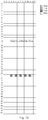
- a sub-frame configuration of reference signals (including PTRSs and DMRSs) is illustrated in Fig.3 , where one sub-frame includes 14 OFDM symbols and 12 sub-carriers; and the abscissa represents the time domain, and the ordinate represents the frequency domain.
- DMRSs are located in the third OFDM symbol, and DMRSs in an OFDM symbol are transmitted via two DMRS ports in a frequency-division multiplexing mode; and one PTRS occupies one sub-carrier, the PTRS port 1 is configured on the fifth sub-carrier, and the PTRS port 2 is configured on the fourth sub-carrier, where PTRSs are transmitted consecutively in the fourth OFDM symbol to the fourteenth OFDM symbol, where in the sub-frame above, the first OFDM symbol to the second OFDM symbol are control channels, and the remaining blank OFDM symbols are transmission channels of data streams.
- the transmitter (e.g., a base station) operates as follows.
- the first data stream to be transmitted is transmitted over the first N1 number of antennas in the transmitter
- the second data stream to be transmitted is transmitted over the last (N-N1) number of antennas in the transmitter, specifically as illustrated in Fig.4 .
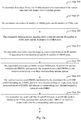
- w 1,1 k is a N 1 ⁇ 1 column vector corresponding to weights for the first N1 number of antennas in precoder used by the first data stream.
- w 2,2 k is a ( N - N 1 ) ⁇ 1 column vector corresponding to weights for the last (N-N1) number of antennas in precoder used by the second data stream.
- the DMRS port 2 corresponds to the last (N-N1) number of antennas in the transmitter
- the transmitter notifies the receiver of the first mapping relationship between the PTRS port 1 and the DMRS port 1, and between the PTRS port 2 to the DMRS port 2 via higher-layer signaling or dynamic control signaling. Also the transmitter notifies the receiver of the second mapping relationship between the first data stream and the DMRS port 1, and between the second data stream and the DMRS port 2 via higher-layer signaling or dynamic control signaling.
- the transmitter can alternatively pre-agree with the receiver on the first mapping relationship and the second mapping relationship instead of notifying the receiver via higher-layer signaling or dynamic control signaling.
- the receiver (e.g., a user equipment) operates as follows.
- Y k,l represents a received signal which is a N r ⁇ 1 column vector, where N r represents the number of receiving antenna ports; P k , l r represents phase noises at the receiver, and is a N r ⁇ N r diagonal matrix, where each element in P k , l r represents a phase noise on a receiving antenna port; H k,l represents a N r ⁇ N t channel matrix, where each element in H k,l represents a channel from an antenna port of the transmitter to an antenna port of the receiver, and N t represents the number of transmitting antenna ports; P k , l t represents noise phases at the transmitter, and is a N t ⁇ N t diagonal matrix, where each element in P k , l t represents a phase noise on a transmitting antenna port; W k,l represents a N t ⁇ N s pre-code matrix; and X k,l represents a transmission signal, and is a N s ⁇ 1
- a channel and a precoder in a sub-frame are not changed, that is, a channel matrix H k,l and a pre-coding matrix W k,l are not changed, and there are N1 elements of e j ⁇ l 0 , and (N-N1) elements of e j ⁇ l 1 , on the diagonal of a phase noise matrix of the transmitter.
- the receiver receives the DMRSs in the third OFDM symbol, and take the first receiving antenna for example, the receiver performs channel estimation using received DMRS 1 via the DMRS port 1, and obtains a channel estimation result e j ⁇ 3 0 ⁇ H 1,1 k ⁇ e j ⁇ 3 0 ⁇ w 1,1 k ; and performs channel estimation using received DMRS2 via the DMRS port 2, and obtains a channel estimation result e j ⁇ 3 0 ⁇ H 1,2 k ⁇ e j ⁇ 3 1 ⁇ w 2,2 k .
- the receiver receives the PTRSs transmitted in two PTRS ports starting with the fourth OFDM symbol, performs channel estimation using received PTRS1 via the PTRS port 1, and obtains a channel estimation result e j ⁇ l 0 ⁇ H 1,1 5 ⁇ e j ⁇ l 0 ⁇ w 1,1 5 , and performs channel estimation using received PTRS2 via the PTRS port 2, and obtains a channel estimation result e j ⁇ l 0 ⁇ H 1,2 4 ⁇ e j ⁇ l 1 ⁇ w 2,2 4 , where l ⁇ 4.
- the receiver receives the first mapping relationship notified by the transmitter via the higher-layer signaling or the dynamic control signaling, or the receiver pre-agrees the first mapping relationship with the transmitter, where in the first mapping relationship, the PTRS port 1 corresponds to the DMRS port 1, and the PTRS port 2 corresponds to the DMRS port 2.
- channel estimation results on the k-th sub-carrier in the l-th OFDM symbol on the first receiving antenna can be obtained as e j ⁇ 3 0 ⁇ H 1,1 k ⁇ e j ⁇ 3 0 ⁇ w 1,1 k ⁇ e j ⁇ l 0 and e j ⁇ 3 0 ⁇ H 1,2 k ⁇ e j ⁇ 3 1 ⁇ w 2,2 k ⁇ e j ⁇ l 1 .
- the receiver receives the second mapping relationship notified by the transmitter via the higher-layer signaling or the dynamic control signaling, or the second mapping relationship is pre-agreed between the receiver and the transmitter, where the second mapping relationship,is a one-to-one correspondence between data streams and DMRS ports; and the receiver demodulates the data stream according to the second mapping relationship, and the compensated channel estimation result of each antenna.
- Fig.5 illustrates a sub-frame configuration of reference signals (including PTRSs and DMRSs), where there are 14 OFDM symbols and 12 sub-carriers in total in a sub-frame; and the abscissa represents the time domain, and the ordinate represents the frequency domain.
- DMRSs are located in the third OFDM symbol, and DMRSs in an OFDM symbol are transmitted via three DMRS ports in a frequency-division multiplexing mode; and one PTRS occupies one sub-carrier, the PTRS port 1 is configured on the fifth sub-carrier, and the PTRS port 2 is configured on the fourth sub-carrier, where PTRSs are transmitted consecutively in the fourth OFDM symbol to the fourteenth OFDM symbol, where the first OFDM symbol to the second OFDM symbol are control channels, and the remaining blank OFDM symbols are transmission channels of data streams, in the sub-frame above.
- the transmitter (e.g., a base station) operates as follows.
- the first data stream to be transmitted is transmitted on the first N1 number of antennas in the transmitter, and the second data stream to be transmitted is transmitted on the last (N-N1) number of antennas of the transmitter, specifically as illustrated in Fig.6 .
- w 1,1 k is a N 1 ⁇ 1 column vector corresponding to weights for the first N1 number of antennas in precoder used by the first data stream.
- w 2,2 k and w 3,2 k are ( N - N 1 ) ⁇ 1 column vectors corresponding to weights for the last (N-N1) number of antennas in precoder used by the second data stream and the third data stream respectively.
- the transmitter notifies the receiver of the first mapping relationship between the PTRS port 1 and the DMRS port 1, and between the PTRS port 2 to the DMRS port 2 via higher-layer signaling or dynamic control signaling. Also the transmitter notifies the receiver of the second mapping relationship between the first data stream and the DMRS port 1, between the second data stream and the DMRS port 2, and between the third data stream and the DMRS port 3 via higher-layer signaling or dynamic control signaling.
- the transmitter can alternatively pre-agree with the receiver on the first mapping relationship and the second mapping relationship instead of notifying the receiver via higher-layer signaling or dynamic control signaling.
- the receiver (e.g., a user equipment) operates as follows.
- Y k,l represents a received signal which is a N r ⁇ 1 column vector, where N r represents the number of receiving antenna ports; P k , l r represents phase noises at the receiver, and is a N r ⁇ N r diagonal matrix, where each element in P k , l r represents a phase noise on a receiving antenna port; H k,l represents a N r ⁇ N t channel matrix, where each element in H k,l represents a channel from an antenna port of the transmitter to an antenna port of the receiver, and N t represents the number of transmitting antenna ports; P k , l t represents noise phases at the transmitter, and is a N t ⁇ N t diagonal matrix, where each element in P k , l t represents a phase noise on a transmitting antenna port; W k,l represents a N t ⁇ N s pre-code matrix; and X k,l represents a transmission signal, and is a N s ⁇ 1
- a channel and a precoder in a sub-frame is not changed, that is, a channel matrix H k,l and a pre-coding matrix W k,l are not changed, and there are N1 elements of e j ⁇ l 0 , and (N-N1) elements of e j ⁇ l 1 , on the diagonal of a phase noise matrix of the transmitter.
- the receiver receives the DMRSs in the third OFDM symbol, and taking the second receiving antenna as an example, the receiver performs channel estimation using received DMRS1 via the DMRS port 1, and obtains a channel estimation result e j ⁇ 3 1 ⁇ H 2,1 k ⁇ e j ⁇ 3 0 ⁇ w 1,1 k ; performs channel estimation using received DMRS2 via the DMRS port 2, and obtains a channel estimation result e j ⁇ 3 1 ⁇ H 2,2 k ⁇ e j ⁇ 3 1 ⁇ w 2,2 k ; and performs channel estimation using received DMRS3 via the DMRS port 3, and obtains a channel estimation result e j ⁇ 3 1 ⁇ H 2,2 k ⁇ e j ⁇ 3 1 ⁇ w 3,2 k .
- the receiver receives the PTRSs transmitted in two PTRS ports starting with the fourth OFDM symbol, performs channel estimation using received PTRS1 via the PTRS port 1, and obtains a channel estimation result e j ⁇ l 1 ⁇ H 2,1 5 ⁇ e j ⁇ l 0 ⁇ w 1,1 5 , and performs channel estimation using received PTRS2 via the PTRS port 2, and obtains a channel estimation result e j ⁇ l 1 ⁇ H 2,2 4 ⁇ e j ⁇ l 1 ⁇ w 2,2 4 + e j ⁇ l 1 ⁇ H 2,2 4 ⁇ e j ⁇ l 1 ⁇ w 3,2 4 , where l ⁇ 4.
- the receiver receives the first mapping relationship notified by the transmitter via the higher-layer signaling or the dynamic control signaling, or the first mapping relationships is pre-agreed between the receiver and the transmitter, where in the first mapping relationship, the PTRS port 1 corresponds to the DMRS port 1, and the PTRS port 2 corresponds to the DMRS port 2 and the DMRS port 3.
- channel estimation results on the k-th sub-carrier in the 1-th OFDM symbol on the second receiving antenna can be obtained as e j ⁇ 3 1 ⁇ H 2,1 k ⁇ e j ⁇ 3 0 ⁇ w 1,1 k ⁇ e j ⁇ l 0 , e j ⁇ 3 1 ⁇ H 2,2 k ⁇ e j ⁇ 3 1 ⁇ w 2,2 k ⁇ e j ⁇ l 1 , and e j ⁇ 3 1 ⁇ H 2,2 k ⁇ e j ⁇ 3 1 ⁇ w 3,2 k ⁇ e j ⁇ l 1 .
- Alike, channel estimation results on the k-th sub-carrier in the 1-th OFDM symbol on the first, third, and fourth receiving antennas can be obtained.
- the receiver receives the second mapping relationship notified by the transmitter via the higher-layer signaling or the dynamic control signaling, or the second mapping relationship is ore-agreed between the receiver and the transmitter, where the second mapping relationship is a one-to-one correspondence between the data streams and DMRS ports; and the receiver demodulates the data stream according to the second mapping relationship, and the compensated channel estimation result of each antenna.
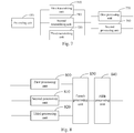
- an apparatus for transmitting a reference signal includes a first transmitting unit 700, a second transmitting unit 710, and a third transmitting unit 720.
- the first transmitting unit 700 is configured to pre-code each data stream, and then transmit each data stream over one or more antenna groups corresponding to each data stream, where antenna elements or antenna ports in the same antenna group have the same phase noise, and all antenna groups corresponding to one data stream have the same phase noise.
- the second transmitting unit 710 is configured to pre-code a Demodulation Reference Signal (DMRS) of each DMRS port, and then transmit each DMRS over corresponding one or more antenna groups, where all antenna groups corresponding to one DMRS port have a same phase noise, and one data stream corresponds to one DMRS port.
- DMRS Demodulation Reference Signal
- the third transmitting unit 730 is configured to pre-code a Phase-Tracking Reference Signal (PTRS) of each PTRS ports, and then transmit each PTRS over corresponding one or more antenna groups, where all antenna groups corresponding to one PTRS port have a same phase noise, and one PTRS port corresponds to at least one PTRS port.
- PTRS Phase-Tracking Reference Signal
- the apparatus further includes a pre-coding unit 750 configured: to pre-code a data stream in such a way that weights for antenna elements or antenna ports in the other antenna groups than an antenna group corresponding to the data stream are zero; to pre-code a DMRS in such a way that weights for antenna elements or antenna ports in the other antenna groups than an antenna group corresponding to the DMRS are zero; and to pre-code a PTRS in such a way that weights for antenna elements or antenna ports in the other antenna groups than an antenna group corresponding to the PTRS are zero.
- a pre-coding unit 750 configured: to pre-code a data stream in such a way that weights for antenna elements or antenna ports in the other antenna groups than an antenna group corresponding to the data stream are zero; to pre-code a DMRS in such a way that weights for antenna elements or antenna ports in the other antenna groups than an antenna group corresponding to the DMRS are zero; and to pre-code a PTRS in such a way that weights for antenna elements
- the apparatus further includes a first processing unit 730 configured: to determine a first mapping relationship between the respective PTRS ports and the respective DMRS ports, where in the first mapping relationship, one PTRS port is mapped to at least one DMRS port, and the PTRS port and its mapped DMRS port use a same antenna group for transmission.
- a first processing unit 730 configured: to determine a first mapping relationship between the respective PTRS ports and the respective DMRS ports, where in the first mapping relationship, one PTRS port is mapped to at least one DMRS port, and the PTRS port and its mapped DMRS port use a same antenna group for transmission.
- the first processing unit 730 is further configured: to transmit the first mapping relationship to a receiver after determining the first mapping relationship; or to pre-agree with a receiver on the first mapping relationship.
- the first processing unit 730 configured to transmit the first mapping relationship to the receiver is configured: to transmit the first mapping relationship to the receiver via higher-layer signaling; or to transmit the first mapping relationship to the receiver via dynamic control signaling.
- the apparatus further includes a second processing unit 740 configured: to determine a second mapping relationship between the respective data streams to be transmitted, and the respective DMRS ports, where in the second mapping relationship, one data stream is mapped to one DMRS port, and the data stream and its mapped DMRS port correspond to a same antenna group for transmission.
- a second processing unit 740 configured: to determine a second mapping relationship between the respective data streams to be transmitted, and the respective DMRS ports, where in the second mapping relationship, one data stream is mapped to one DMRS port, and the data stream and its mapped DMRS port correspond to a same antenna group for transmission.
- the second processing unit 740 is further configured: to transmit the second mapping relationship to a receiver after determining the second mapping relationship; or to pre-agree with a receiver on the second mapping relationship.
- the second processing unit 740 configured to transmit the second mapping relationship to the receiver is configured: to transmit the second mapping relationships to the receiver via higher-layer signaling; or to transmit the second mapping relationships to the receiver via dynamic control signaling.
- precoder used by the apparatus for a PTRS is the same as or related to precoder used by a data stream over a sub-carrier occupied by the PTRS, the data stream corresponds to a DMRS port corresponding the PTRS.
- precoder used by the apparatus for a DMRS is the same as or related to precoder used by a data stream over a sub-carrier occupied by the DMRS port, the data stream corresponding to the DMRS port.
- an apparatus for determining phase noise includes a first processing unit 800, a second processing unit 810, a third processing unit 830, and a fourth processing unit 840.
- the first processing unit 800 is configured to receive a Demodulation Reference Signal (DMRS) transmitted by a transmitter respectively over one or more antenna groups corresponding to each DMRS port, to perform first channel estimation respectively based upon each received DMRS, and to obtain a corresponding first channel estimation result of each DMRS.
- DMRS Demodulation Reference Signal
- the second processing unit 810 is configured to receive a Phase-Tracking Reference Signal (PTRS) transmitted by the transmitter respectively over one or more antenna groups corresponding to each PTRS port, to perform second channel estimation respectively based upon each received PTRS, and to obtain a corresponding second channel estimation result of each PTRS.
- PTRS Phase-Tracking Reference Signal
- the third processing unit 820 is configured to determine a first mapping relationship, where the first mapping relationship represents a correspondence relationship between the respective PTRS ports and the respective DMRS ports, one PTRS port corresponds to at least one DMRS port, and the PTRS port and its corresponding DMRS port use a same antenna group for transmission.
- the fourth processing unit 830 is configured to calculate a phase change, in a symbol including the PTRS, arising from a phase noise of the antenna groups corresponding to each PTRS port respectively using the second channel estimation result of each PTRS and the first channel estimation result of corresponding DMRS based upon the first mapping relationship.
- the first mapping relationship is obtained by the apparatus as notified by the transmitter, or the first mapping relationship is pre-agreed between the apparatus and the transmitter.
- the apparatus further includes a fifth processing unit 840 configured: to receive respective data streams transmitted by the transmitter respectively over their corresponding antenna groups; to determine a second mapping relationship, where the second mapping relationship represents a correspondence relationship between the respective data streams and the respective DMRS ports, one data stream corresponds to one DMRS port, and the data stream and its corresponding DMRS port correspond to a same antenna group for transmission; and to perform the following operations respectively on each data stream based upon the second mapping relationship: determining a first channel estimation result estimated on a DMRS port corresponding to the data stream; compensating for the first channel estimation result using a phase change arising from phase noise of an antenna group corresponding to the DMRS port; and demodulating the data stream using the compensated first channel estimation result.
- a fifth processing unit 840 configured: to receive respective data streams transmitted by the transmitter respectively over their corresponding antenna groups; to determine a second mapping relationship, where the second mapping relationship represents a correspondence relationship between the respective data streams and the respective DMRS ports, one data stream corresponds to one DMRS port
- the second mapping relationship is obtained by the apparatus as notified by the transmitter, or the second mapping relationship is pre-agreed between the apparatus and the transmitter.
- an apparatus for transmitting a reference signal includes a processor 900, a transceiver 901, and a memory 902.
- the processor 900 is configured to read and execute program in the memory 902: to transmit data streams, DMRSs, and PTRSs through the transceiver 901; to pre-code each data stream, and then transmit each data stream over corresponding one or more antenna groups, where antenna elements or antenna ports in the same antenna group have the same phase noise, and all antenna groups corresponding to one data stream have the same phase noise; to pre-code a DMRS of each DMRS port, and then transmit each DMRS over corresponding one or more antenna groups, where all antenna groups corresponding to one DMRS port have a same phase noise, and one data stream corresponds to one DMRS port; to pre-code a PTRS of each PTRS port, and then transmit each PTRS over corresponding one or more antenna groups, where all antenna groups corresponding to one PTRS port have a same phase noise, and one PTRS port corresponds to at least one PTRS port.
- the transceiver 901 is configured to transmit and receive data under the control of the processor 900.
- the processor 900 is configured: to pre-code a data stream in such a way that weights for antenna elements or antenna ports in the other antenna groups than an antenna group corresponding to the data stream are zero; to pre-code a DMRS in such a way that weights for antenna elements or antenna ports in the other antenna groups than an antenna group corresponding to the DMRS are zero; and to pre-code a PTRS in such a way that weights for antenna elements or antenna ports in the other antenna groups than an antenna group corresponding to the PTRS are zero.
- the processor 900 is configured: to determine a first mapping relationship between the respective PTRS ports and the respective DMRS ports, where in the first mapping relationship, one PTRS port is mapped to at least one DMRS port, and the PTRS port and its mapped DMRS port use a same antenna group for transmission.
- the processor 900 is configured: to transmit the first mapping relationship to a receiver after determining the first mapping relationship; or to pre-agree with a receiver on the first mapping relationship.
- the processor 900 configured to transmit the first mapping relationship to the receiver is configured: to transmit the first mapping relationship to the receiver via higher-layer signaling; or to transmit the first mapping relationship to the receiver via dynamic control signaling.
- the processor 900 is configured: to determine a second mapping relationship between the respective data streams to be transmitted and the respective DMRS ports, where in the second mapping relationship, one data stream is mapped to one DMRS port, and the data stream and its mapped DMRS port correspond to a same antenna group for transmission.
- the processor 900 is configured: to transmit the second mapping relationship to a receiver after determining the second mapping relationships; or to pre-agree with a receiver on the second mapping relationship.
- the processor 900 configured to transmit the second mapping relationship to the receiver is configured: to transmit the second mapping relationship to the receiver via higher-layer signaling; or to transmit the second mapping relationship to the receiver via dynamic control signaling.
- precoder used by the processor 900 for a PTRS is the same as or related to precoder used by a data stream over a sub-carrier occupied by the PTRS, the data stream corresponds to a DMRS port corresponding to the PTRS.
- precoder used by the processor 900 for a DMRS is the same as or related to precoder used by a data stream over a sub-carrier occupied by the DMRS port, the data stream corresponds to the DMRS port.
- the bus architecture can include any number of interconnecting buses and bridges to particularly link together various circuits including one or more processors represented by the processor 900, and one or more memories represented by the memory 920.
- the bus architecture can further link together various other circuits, e.g., a peripheral device, a manostat, a power management circuit, etc., all of which are well known in the art, so a further description thereof will be omitted in this context.
- the bus interface serves as an interface.
- the transceiver 910 can be a number of elements, e.g., a transmitter and a receiver, which are units for communication with various other devices over a transmission medium.
- an apparatus for determining phase noise includes a processor 100, a transceiver 101, a memory 102, and a user interface 103.
- the processor 100 is configured to read and execute program in the memory 102: to receive data streams, DMRSs, and PTRSs through the transceiver 101; to receive a DMRS transmitted by a transmitter respectively over one or more antenna groups corresponding to each DMRS port, to perform first channel estimation respectively based upon each received DMRS, and to obtain a corresponding first channel estimation result corresponding to each DMRS; to receive a PTRS transmitted by the transmitter respectively over one or more antenna groups corresponding to each PTRS port, to perform second channel estimation respectively based upon each received PTRS, and to obtain a corresponding second channel estimation result corresponding to each PTRS; to determine a first mapping relationship, where the first mapping relationship represents a correspondence relationship between the respective PTRS ports and the respective DMRS ports, one PTRS port corresponds to at least one DMRS port, and the PTRS port and its corresponding DMRS port use a same antenna group for transmission; and to calculate a phase change, in a symbol including the PTRS, arising
- the transceiver 101 is configured to transmit and receive data under the control of the processor 100.
- the first mapping relationship is obtained by the processor 100 as notified by the transmitter, or the first mapping relationship is pre-agreed between the processor 100 and the transmitter.
- the processor 100 is configured: to receive respective data streams transmitted by the transmitter respectively over their corresponding antenna groups; to determine a second mapping relationship, where the second mapping relationship represents a correspondence relationship between the respective data streams and the respective DMRS ports, one data stream corresponds to one DMRS port, and the data stream and its corresponding DMRS port correspond to a same antenna group for transmission; and to perform the following operations respectively on each data stream based upon the second mapping relationship: determining a first channel estimation result estimated on a DMRS port corresponding to the data stream; compensating for the first channel estimation result using a phase change arising from phase noise of an antenna group corresponding to the DMRS port; and demodulating the data stream using the compensated first channel estimation result.
- the second mapping relationship is obtained by the processor 100 as notified by the transmitter, or the second mapping relationship is pre-agreed between the processor 100 and the transmitter.
- the bus architecture can include any number of interconnecting buses and bridges to particularly link together various circuits including one or more processors represented by the processor 100, and one or more memories represented by the memory 102.
- the bus architecture can further link together various other circuits, e.g., a peripheral device, a manostat, a power management circuit, etc., all of which are well known in the art, so a further description thereof will be omitted in this context.
- the bus interface serves as an interface.
- the transceiver 101 can be a number of elements, e.g., a transmitter and a receiver, which are units for communication with various other devices over a transmission medium.
- the user interface 103 can also be an interface via which devices are connected internally and externally as needed, and the connected devices include but will not be limited to a keypad, a monitor, a speaker, a microphone, a joystick, etc.
- the processor 100 is responsible for managing the bus architecture and performing normal processes, and the memory 102 can store data for use by the processor 100 in performing the operations.
- the transmitter transmits respective pre-coded user data streams respectively over their corresponding antenna groups with the same phase noise to the receiver, transmits respective pre-coded DMRSs respectively over their corresponding antenna groups with the same phase noise to the receiver, and transmits respective pre-coded PTRSs respectively over their corresponding antenna groups with the same phase noise to the receiver, where antenna elements or antenna port elements or antenna ports in the same antenna group have the same phase noise.
- the receiver Upon reception of the PTRSs, the receiver performs channel estimation based upon the respective received PTRSs, determines phase changes arising from phase noise corresponding to the different antenna groups, and compensates for channel estimation results of DMRS ports corresponding to the different antenna groups using the phase changes arising from phase noise corresponding to the different antenna groups, and demodulates the data streams transmitted over the corresponding antenna groups using the compensated channel estimation results, so that even if there is different phase noise of the different antennas of the transmitter, then the receiver can determine the phase changes arising from the different phase noise accurately to thereby demodulate all the data transmitted over the different antenna groups accurately according to the different phase changes.
- the embodiments of the invention can be embodied as a method, a system or a computer program product. Therefore the invention can be embodied in the form of an all-hardware embodiment, an all-software embodiment or an embodiment of software and hardware in combination. Furthermore the invention can be embodied in the form of a computer program product embodied in one or more computer useable storage mediums (including but not limited to a disk memory, a CD-ROM, an optical memory, etc.) in which computer useable program codes are contained.
- a computer useable storage mediums including but not limited to a disk memory, a CD-ROM, an optical memory, etc.
- These computer program instructions can also be stored into a computer readable memory capable of directing the computer or the other programmable data processing device to operate in a specific manner so that the instructions stored in the computer readable memory create an article of manufacture including instruction means which perform the functions specified in the flow(s) of the flow chart and/or the block(s) of the block diagram.
- These computer program instructions can also be loaded onto the computer or the other programmable data processing device so that a series of operational steps are performed on the computer or the other programmable data processing device to create a computer implemented process so that the instructions executed on the computer or the other programmable device provide steps for performing the functions specified in the flow(s) of the flow chart and/or the block(s) of the block diagram.
Landscapes
- Engineering & Computer Science (AREA)
- Signal Processing (AREA)
- Computer Networks & Wireless Communication (AREA)
- Power Engineering (AREA)
- Radio Transmission System (AREA)
- Mobile Radio Communication Systems (AREA)
Applications Claiming Priority (2)
| Application Number | Priority Date | Filing Date | Title |
|---|---|---|---|
| CN201611239760.3A CN108259401B (zh) | 2016-12-28 | 2016-12-28 | 参考信号发送方法和相位噪声确定方法及相关装置 |
| PCT/CN2017/099106 WO2018120875A1 (fr) | 2016-12-28 | 2017-08-25 | Procédé de transmission d'un signal de référence, procédé de détermination d'un bruit de phase, et appareils associés |
Publications (3)
| Publication Number | Publication Date |
|---|---|
| EP3565205A1 true EP3565205A1 (fr) | 2019-11-06 |
| EP3565205A4 EP3565205A4 (fr) | 2019-12-18 |
| EP3565205B1 EP3565205B1 (fr) | 2021-02-17 |
Family
ID=62706867
Family Applications (1)
| Application Number | Title | Priority Date | Filing Date |
|---|---|---|---|
| EP17888540.6A Active EP3565205B1 (fr) | 2016-12-28 | 2017-08-25 | Procédé de transmission d'un signal de référence, procédé de détermination d'un bruit de phase, et appareils associés |
Country Status (7)
| Country | Link |
|---|---|
| US (1) | US10659119B2 (fr) |
| EP (1) | EP3565205B1 (fr) |
| JP (1) | JP6980169B2 (fr) |
| KR (1) | KR102269300B1 (fr) |
| CN (1) | CN108259401B (fr) |
| TW (1) | TWI659623B (fr) |
| WO (1) | WO2018120875A1 (fr) |
Cited By (2)
| Publication number | Priority date | Publication date | Assignee | Title |
|---|---|---|---|---|
| US20190327056A1 (en) * | 2017-01-05 | 2019-10-24 | Huawei Technologies Co., Ltd. | Reference signal sending method and communications device |
| EP4436088A3 (fr) * | 2018-11-15 | 2024-12-25 | QUALCOMM Incorporated | Détermination d'un signal de référence de démodulation |
Families Citing this family (33)
| Publication number | Priority date | Publication date | Assignee | Title |
|---|---|---|---|---|
| CN115622674B (zh) * | 2017-02-07 | 2024-12-24 | 中兴通讯股份有限公司 | 一种相位噪声导频的配置、确定方法及装置 |
| CA3032798C (fr) | 2017-03-25 | 2022-07-19 | Lg Electronics Inc. | Methode et dispositif de reception de ptrs servant a annuler le bruit dephase dans un systeme de communication sans fil |
| JP6883659B2 (ja) * | 2017-04-28 | 2021-06-09 | パナソニック インテレクチュアル プロパティ コーポレーション オブ アメリカPanasonic Intellectual Property Corporation of America | 測定装置及び測定方法 |
| EP4075711B1 (fr) | 2017-06-12 | 2024-03-06 | Panasonic Intellectual Property Corporation of America | Transmetteur, récepteur, procédé de transmission et procédé de réception |
| US10341066B2 (en) * | 2017-08-03 | 2019-07-02 | Samsung Electronics Co., Ltd. | System and method for common phase error and inter-carrier interference estimation and compensation |
| US10951290B2 (en) * | 2017-10-26 | 2021-03-16 | Apple Inc. | Channel state information report for phase tracking reference signal port selection |
| CN109803253B (zh) * | 2017-11-17 | 2020-06-23 | 维沃移动通信有限公司 | 一种信号传输方法、终端及网络设备 |
| WO2019235756A1 (fr) * | 2018-06-07 | 2019-12-12 | 엘지전자 주식회사 | Procédé de transmission ou de réception de signal de référence de suivi de phase entre un terminal et une station de base dans un système de communication sans fil, et appareil prenant le en charge |
| JP7248099B2 (ja) * | 2018-08-03 | 2023-03-29 | 日本電気株式会社 | 通信のための方法 |
| CN109257308B (zh) * | 2018-09-19 | 2021-01-05 | 中国联合网络通信集团有限公司 | 一种相位噪声估计方法及装置 |
| US10484072B1 (en) | 2018-09-28 | 2019-11-19 | At&T Intellectual Property I, L.P. | Determining channel state information in 5G wireless communication systems with phase tracking |
| CN114866211A (zh) * | 2018-10-12 | 2022-08-05 | 华为技术有限公司 | 数据传输方法和通信装置 |
| CN113438724B (zh) | 2019-03-18 | 2022-03-25 | 大唐移动通信设备有限公司 | 时钟偏移确定及其处理方法、装置、系统 |
| WO2020248280A1 (fr) * | 2019-06-14 | 2020-12-17 | Oppo广东移动通信有限公司 | Procédé de communication sans fil, dispositif de réseau et dispositif terminal |
| WO2021084333A1 (fr) * | 2019-10-31 | 2021-05-06 | Lenovo (Singapore) Pte. Ltd. | Transmission à l'aide d'un type de forme d'onde de liaison descendante adapté |
| EP4089950B1 (fr) | 2020-01-17 | 2025-04-16 | LG Electronics Inc. | Procédé de fonctionnement d'eu associé à un ptrs de liaison latérale dans un système de communication sans fil |
| CN113259275B (zh) * | 2020-02-11 | 2022-06-07 | 大唐移动通信设备有限公司 | 一种信道估计方法、装置及接收机 |
| KR20210141229A (ko) * | 2020-05-15 | 2021-11-23 | 삼성전자주식회사 | 전자 장치 및 전자 장치에서 기준 신호를 전송하는 방법 |
| WO2022016503A1 (fr) * | 2020-07-24 | 2022-01-27 | Qualcomm Incorporated | Configurations de signal de référence de suivi de phase multiple pour un équipement utilisateur |
| CN114070682B (zh) * | 2020-07-31 | 2022-10-04 | 华为技术有限公司 | 相位噪声估计方法和装置 |
| CN112398764B (zh) * | 2020-11-05 | 2021-06-29 | 上海擎昆信息科技有限公司 | 一种联合dmrs和ptrs的频偏估计方法及系统 |
| WO2022139875A1 (fr) * | 2020-12-21 | 2022-06-30 | Zeku, Inc. | Appareil et procédé de correction de bruit de phase dans des systèmes de communication sans fil |
| CN114826839B (zh) * | 2021-01-27 | 2024-11-05 | 大唐移动通信设备有限公司 | 相位噪声补偿方法、终端设备及网络设备 |
| KR20220147449A (ko) | 2021-04-27 | 2022-11-03 | 삼성전자주식회사 | 운반파 묶음을 지원하는 무선 통신 장치 및 이의 동작 방법 |
| US11601150B1 (en) | 2021-11-17 | 2023-03-07 | Ultralogic 6G, Llc | Demodulation for phase-noise mitigation in 5G and 6G |
| US11736320B2 (en) * | 2022-02-14 | 2023-08-22 | Ultralogic 6G, Llc | Multiplexed amplitude-phase modulation for 5G/6G noise mitigation |
| US12250100B2 (en) * | 2022-02-14 | 2025-03-11 | David E. Newman | Selecting a modulation scheme responsive to fault types in 5G/6G |
| JP2025524877A (ja) * | 2022-08-04 | 2025-08-01 | エルジー エレクトロニクス インコーポレイティド | 無線通信システムにおけるマルチパネル同時送信のための位相追跡参照信号の送信方法及びそのための装置 |
| US11558236B1 (en) | 2022-09-06 | 2023-01-17 | Ultralogic 6G, Llc | Single-branch reference for high-frequency phase tracking in 5G and 6G |
| US11637649B2 (en) | 2022-09-06 | 2023-04-25 | Ultralogic 6G, Llc | Phase-noise mitigation at high frequencies in 5G and 6G |
| US11799707B2 (en) | 2022-09-06 | 2023-10-24 | Ultralogic 6G, Llc | Guard-space phase-tracking reference signal for 5G and 6G networking |
| CN116132241B (zh) * | 2023-02-20 | 2024-11-29 | 东南大学 | 一种多通道无线通信系统的协作相位噪声估计方法 |
| WO2025086272A1 (fr) * | 2023-10-27 | 2025-05-01 | 华为技术有限公司 | Procédé et appareil de communication |
Family Cites Families (18)
| Publication number | Priority date | Publication date | Assignee | Title |
|---|---|---|---|---|
| US20080101497A1 (en) | 2006-10-30 | 2008-05-01 | Broadcom Corporation, A California Corporation | MIMO phase noise estimation and correction |
| US8948196B2 (en) * | 2010-05-03 | 2015-02-03 | Qualcomm Incorporated | Method and apparatus for sounding antennas in wireless communication |
| KR101348052B1 (ko) * | 2010-06-21 | 2014-01-03 | 후지쯔 가부시끼가이샤 | 기준 신호 송신 방법, 채널 품질 추정 방법, 이동국, 기지국 및 무선 통신 시스템 |
| HUE030536T2 (en) | 2010-10-11 | 2017-05-29 | Intel Corp | Upload Direction Noise Estimation for Virtual MIMO |
| CN103139115B (zh) * | 2011-11-25 | 2016-08-03 | 华为技术有限公司 | 一种干扰对齐方法、装置及系统 |
| US9231809B2 (en) * | 2012-08-17 | 2016-01-05 | Intel Corporation | Methods and arrangements for phase tracking in wireless networks |
| US9769812B2 (en) * | 2012-09-18 | 2017-09-19 | Lg Electronics Inc. | Method and apparatus for receiving system information in wireless communication system |
| US20150358061A1 (en) * | 2013-01-23 | 2015-12-10 | Telefonaktiebolaget L M Ericsson (Publ) | Radio base station and method for precoding signal |
| CN108111291B (zh) * | 2013-01-25 | 2021-08-20 | 华为技术有限公司 | 解调参考信号传输装置和计算机可读存储介质 |
| EP2768189A3 (fr) | 2013-02-15 | 2014-10-08 | Rohde & Schwarz GmbH & Co. KG | Dispositif de mesure et procédé de mesure de paramètres d'estimation conjointe |
| US10097254B2 (en) * | 2016-04-18 | 2018-10-09 | Qualcomm Incorporated | Channel state information estimation and channel information reporting |
| US10116483B2 (en) * | 2016-04-18 | 2018-10-30 | Qualcomm Incorporated | Dynamically convey information of demodulation reference signal and phase noise compensation reference signal |
| KR101910662B1 (ko) * | 2016-06-09 | 2018-10-23 | 엘지전자 주식회사 | 무선 통신 시스템에서 위상 잡음 보상 참조 신호를 송수신하기 위한 방법 및 이를 위한 장치 |
| KR102380756B1 (ko) * | 2016-08-05 | 2022-03-31 | 삼성전자 주식회사 | 무선 통신 시스템에서 위상 보상 기준 신호를 송수신하는 방법 및 장치 |
| US10595225B2 (en) * | 2016-09-13 | 2020-03-17 | Qualcomm Incorporated | Phase-noise compensation reference signal configuration reporting and signaling |
| EP3535884A1 (fr) * | 2016-11-04 | 2019-09-11 | Telefonaktiebolaget LM Ericsson (publ) | Configuration de pt-rs en fonction de paramètres de planification |
| US10411914B2 (en) * | 2016-12-14 | 2019-09-10 | Intel IP Corporation | Data detection in MIMO systems with demodulation and tracking reference signals |
| CN108259143B (zh) * | 2016-12-28 | 2020-02-28 | 电信科学技术研究院 | 一种参考信号的传输方法、发送端和接收端 |
-
2016
- 2016-12-28 CN CN201611239760.3A patent/CN108259401B/zh active Active
-
2017
- 2017-08-25 US US16/475,072 patent/US10659119B2/en active Active
- 2017-08-25 JP JP2019535819A patent/JP6980169B2/ja active Active
- 2017-08-25 WO PCT/CN2017/099106 patent/WO2018120875A1/fr not_active Ceased
- 2017-08-25 KR KR1020197022077A patent/KR102269300B1/ko active Active
- 2017-08-25 EP EP17888540.6A patent/EP3565205B1/fr active Active
- 2017-11-21 TW TW106140289A patent/TWI659623B/zh active
Cited By (4)
| Publication number | Priority date | Publication date | Assignee | Title |
|---|---|---|---|---|
| US20190327056A1 (en) * | 2017-01-05 | 2019-10-24 | Huawei Technologies Co., Ltd. | Reference signal sending method and communications device |
| US11082179B2 (en) * | 2017-01-05 | 2021-08-03 | Huawei Technologies Co., Ltd. | Reference signal sending method and communications device |
| US11764925B2 (en) | 2017-01-05 | 2023-09-19 | Huawei Technologies Co., Ltd. | Reference signal sending method and communications device |
| EP4436088A3 (fr) * | 2018-11-15 | 2024-12-25 | QUALCOMM Incorporated | Détermination d'un signal de référence de démodulation |
Also Published As
| Publication number | Publication date |
|---|---|
| TWI659623B (zh) | 2019-05-11 |
| US20190326964A1 (en) | 2019-10-24 |
| JP2020503782A (ja) | 2020-01-30 |
| TW201824763A (zh) | 2018-07-01 |
| KR102269300B1 (ko) | 2021-06-24 |
| CN108259401A (zh) | 2018-07-06 |
| EP3565205A4 (fr) | 2019-12-18 |
| KR20190097265A (ko) | 2019-08-20 |
| WO2018120875A1 (fr) | 2018-07-05 |
| US10659119B2 (en) | 2020-05-19 |
| JP6980169B2 (ja) | 2021-12-15 |
| EP3565205B1 (fr) | 2021-02-17 |
| CN108259401B (zh) | 2020-09-15 |
Similar Documents
| Publication | Publication Date | Title |
|---|---|---|
| US10659119B2 (en) | Method for transmitting a reference signal, method for determining phase noise and related apparatuses | |
| WO2018202206A1 (fr) | Procédés et appareil d'acquisition d'informations d'état de canal associés à la réciprocité de canal | |
| US9094064B2 (en) | Systems and methods for beamforming in a massive MIMO system | |
| US10862644B2 (en) | Method and apparatus for phase compensation using phase-tracking reference signal | |
| RU2527930C2 (ru) | Способ и устройство предварительного кодирования на основе опорных сигналов демодуляции смешанного мультиплексирования | |
| US8913674B2 (en) | Method and apparatus for transmitting and receiving codebook subset restriction bitmap | |
| CN107371250B (zh) | 指令的发送方法及装置、指令的接收方法及装置 | |
| WO2018028657A1 (fr) | Procédé d'envoi de données, et procédé, appareil et système d'envoi de signalisation | |
| EP3681054A1 (fr) | Procédé de transmission à antennes multiples, terminal et station de base | |
| CN110971275A (zh) | 一种上行传输方法、上行传输的调度方法和设备 | |
| KR20130122646A (ko) | 채널 상태를 리포팅하는 방법 및 장치 | |
| KR20140016874A (ko) | 송신 장치, 수신 장치, 송신 방법 및 수신 방법 | |
| CN106856461A (zh) | 一种干扰估计方法和设备 | |
| CN108259145A (zh) | 一种数据传输方法、发送装置及接收装置 | |
| CN111182631B (zh) | 一种上行传输方法和设备 | |
| CN105917592B (zh) | 信息处理装置、网络节点和信息处理方法 | |
| CN108418662B (zh) | 一种参考信号的发送方法、接收方法及相关设备 | |
| CN111316692A (zh) | 信道状态信息的反馈方法、通信装置和系统 | |
| CN106105121B (zh) | 用于在大规模mimo系统中获取下行数据的方法与设备 | |
| CN112866153B (zh) | 干扰消除的方法、装置及系统 |
Legal Events
| Date | Code | Title | Description |
|---|---|---|---|
| STAA | Information on the status of an ep patent application or granted ep patent |
Free format text: STATUS: THE INTERNATIONAL PUBLICATION HAS BEEN MADE |
|
| PUAI | Public reference made under article 153(3) epc to a published international application that has entered the european phase |
Free format text: ORIGINAL CODE: 0009012 |
|
| STAA | Information on the status of an ep patent application or granted ep patent |
Free format text: STATUS: REQUEST FOR EXAMINATION WAS MADE |
|
| 17P | Request for examination filed |
Effective date: 20190703 |
|
| AK | Designated contracting states |
Kind code of ref document: A1 Designated state(s): AL AT BE BG CH CY CZ DE DK EE ES FI FR GB GR HR HU IE IS IT LI LT LU LV MC MK MT NL NO PL PT RO RS SE SI SK SM TR |
|
| AX | Request for extension of the european patent |
Extension state: BA ME |
|
| XX | Miscellaneous (additional remarks) |
Free format text: DER ANMELDER HAT EINEN TEXT ZUM ZWECKE DER ANPASSUNG DER UEBERSETZUNG AN DIE ANMELDUNG IN IHRER URSPRUENGLICHEN FASSUNG EINGEREICHT (ART. 14 (2) EPUE).THE APPLICANT HAS FILED A TEXT WITH WHICH IT IS INTENDED TO BRING THE TRANSLATION INTO CONFORMITY WITH THE APPLICATION AS FILED (ART. 14(2) EPC).LE DEMANDEUR A DEPOSE UN TEXTE DESTINE A RENDRE LA TRADUCTION CONFORME AU TEXTE DE LA DEMANDE TELLE QU'ELLE A ETE DEPOSEE (ART. 14(2) CBE). |
|
| A4 | Supplementary search report drawn up and despatched |
Effective date: 20191118 |
|
| RIC1 | Information provided on ipc code assigned before grant |
Ipc: H04B 7/06 20060101ALI20191112BHEP Ipc: H04B 7/0456 20170101ALI20191112BHEP Ipc: H04L 27/26 20060101AFI20191112BHEP Ipc: H04L 5/00 20060101ALI20191112BHEP |
|
| DAV | Request for validation of the european patent (deleted) | ||
| DAX | Request for extension of the european patent (deleted) | ||
| GRAP | Despatch of communication of intention to grant a patent |
Free format text: ORIGINAL CODE: EPIDOSNIGR1 |
|
| STAA | Information on the status of an ep patent application or granted ep patent |
Free format text: STATUS: GRANT OF PATENT IS INTENDED |
|
| INTG | Intention to grant announced |
Effective date: 20201016 |
|
| GRAS | Grant fee paid |
Free format text: ORIGINAL CODE: EPIDOSNIGR3 |
|
| GRAA | (expected) grant |
Free format text: ORIGINAL CODE: 0009210 |
|
| STAA | Information on the status of an ep patent application or granted ep patent |
Free format text: STATUS: THE PATENT HAS BEEN GRANTED |
|
| AK | Designated contracting states |
Kind code of ref document: B1 Designated state(s): AL AT BE BG CH CY CZ DE DK EE ES FI FR GB GR HR HU IE IS IT LI LT LU LV MC MK MT NL NO PL PT RO RS SE SI SK SM TR |
|
| REG | Reference to a national code |
Ref country code: GB Ref legal event code: FG4D |
|
| XX | Miscellaneous (additional remarks) |
Free format text: DER ANMELDER HAT EINEN TEXT ZUM ZWECKE DER ANPASSUNG DER UEBERSETZUNG AN DIE ANMELDUNG IN IHRER URSPRUENGLICHEN FASSUNG EINGEREICHT (ART. 14 (2) EPUE).THE APPLICANT HAS FILED A TEXT WITH WHICH IT IS INTENDED TO BRING THE TRANSLATION INTO CONFORMITY WITH THE APPLICATION AS FILED (ART. 14(2) EPC).LE DEMANDEUR A DEPOSE UN TEXTE DESTINE A RENDRE LA TRADUCTION CONFORME AU TEXTE DE LA DEMANDE TELLE QU'ELLE A ETE DEPOSEE (ART. 14(2) CBE). |
|
| REG | Reference to a national code |
Ref country code: CH Ref legal event code: EP |
|
| REG | Reference to a national code |
Ref country code: DE Ref legal event code: R096 Ref document number: 602017033018 Country of ref document: DE |
|
| REG | Reference to a national code |
Ref country code: AT Ref legal event code: REF Ref document number: 1362978 Country of ref document: AT Kind code of ref document: T Effective date: 20210315 |
|
| REG | Reference to a national code |
Ref country code: IE Ref legal event code: FG4D |
|
| REG | Reference to a national code |
Ref country code: LT Ref legal event code: MG9D |
|
| REG | Reference to a national code |
Ref country code: NL Ref legal event code: MP Effective date: 20210217 |
|
| PG25 | Lapsed in a contracting state [announced via postgrant information from national office to epo] |
Ref country code: HR Free format text: LAPSE BECAUSE OF FAILURE TO SUBMIT A TRANSLATION OF THE DESCRIPTION OR TO PAY THE FEE WITHIN THE PRESCRIBED TIME-LIMIT Effective date: 20210217 Ref country code: FI Free format text: LAPSE BECAUSE OF FAILURE TO SUBMIT A TRANSLATION OF THE DESCRIPTION OR TO PAY THE FEE WITHIN THE PRESCRIBED TIME-LIMIT Effective date: 20210217 Ref country code: GR Free format text: LAPSE BECAUSE OF FAILURE TO SUBMIT A TRANSLATION OF THE DESCRIPTION OR TO PAY THE FEE WITHIN THE PRESCRIBED TIME-LIMIT Effective date: 20210518 Ref country code: NO Free format text: LAPSE BECAUSE OF FAILURE TO SUBMIT A TRANSLATION OF THE DESCRIPTION OR TO PAY THE FEE WITHIN THE PRESCRIBED TIME-LIMIT Effective date: 20210517 Ref country code: PT Free format text: LAPSE BECAUSE OF FAILURE TO SUBMIT A TRANSLATION OF THE DESCRIPTION OR TO PAY THE FEE WITHIN THE PRESCRIBED TIME-LIMIT Effective date: 20210617 Ref country code: BG Free format text: LAPSE BECAUSE OF FAILURE TO SUBMIT A TRANSLATION OF THE DESCRIPTION OR TO PAY THE FEE WITHIN THE PRESCRIBED TIME-LIMIT Effective date: 20210517 Ref country code: LT Free format text: LAPSE BECAUSE OF FAILURE TO SUBMIT A TRANSLATION OF THE DESCRIPTION OR TO PAY THE FEE WITHIN THE PRESCRIBED TIME-LIMIT Effective date: 20210217 |
|
| REG | Reference to a national code |
Ref country code: AT Ref legal event code: MK05 Ref document number: 1362978 Country of ref document: AT Kind code of ref document: T Effective date: 20210217 |
|
| REG | Reference to a national code |
Ref country code: DE Ref legal event code: R081 Ref document number: 602017033018 Country of ref document: DE Owner name: DATANG MOBILE COMMUNICATIONS EQUIPMENT CO., LT, CN Free format text: FORMER OWNER: CHINA ACADEMY OF TELECOMMUNICATIONS TECHNOLOGY, BEIJING, CN |
|
| PG25 | Lapsed in a contracting state [announced via postgrant information from national office to epo] |
Ref country code: LV Free format text: LAPSE BECAUSE OF FAILURE TO SUBMIT A TRANSLATION OF THE DESCRIPTION OR TO PAY THE FEE WITHIN THE PRESCRIBED TIME-LIMIT Effective date: 20210217 Ref country code: NL Free format text: LAPSE BECAUSE OF FAILURE TO SUBMIT A TRANSLATION OF THE DESCRIPTION OR TO PAY THE FEE WITHIN THE PRESCRIBED TIME-LIMIT Effective date: 20210217 Ref country code: PL Free format text: LAPSE BECAUSE OF FAILURE TO SUBMIT A TRANSLATION OF THE DESCRIPTION OR TO PAY THE FEE WITHIN THE PRESCRIBED TIME-LIMIT Effective date: 20210217 Ref country code: RS Free format text: LAPSE BECAUSE OF FAILURE TO SUBMIT A TRANSLATION OF THE DESCRIPTION OR TO PAY THE FEE WITHIN THE PRESCRIBED TIME-LIMIT Effective date: 20210217 Ref country code: SE Free format text: LAPSE BECAUSE OF FAILURE TO SUBMIT A TRANSLATION OF THE DESCRIPTION OR TO PAY THE FEE WITHIN THE PRESCRIBED TIME-LIMIT Effective date: 20210217 |
|
| PG25 | Lapsed in a contracting state [announced via postgrant information from national office to epo] |
Ref country code: IS Free format text: LAPSE BECAUSE OF FAILURE TO SUBMIT A TRANSLATION OF THE DESCRIPTION OR TO PAY THE FEE WITHIN THE PRESCRIBED TIME-LIMIT Effective date: 20210617 |
|
| PG25 | Lapsed in a contracting state [announced via postgrant information from national office to epo] |
Ref country code: CZ Free format text: LAPSE BECAUSE OF FAILURE TO SUBMIT A TRANSLATION OF THE DESCRIPTION OR TO PAY THE FEE WITHIN THE PRESCRIBED TIME-LIMIT Effective date: 20210217 Ref country code: EE Free format text: LAPSE BECAUSE OF FAILURE TO SUBMIT A TRANSLATION OF THE DESCRIPTION OR TO PAY THE FEE WITHIN THE PRESCRIBED TIME-LIMIT Effective date: 20210217 Ref country code: AT Free format text: LAPSE BECAUSE OF FAILURE TO SUBMIT A TRANSLATION OF THE DESCRIPTION OR TO PAY THE FEE WITHIN THE PRESCRIBED TIME-LIMIT Effective date: 20210217 Ref country code: SM Free format text: LAPSE BECAUSE OF FAILURE TO SUBMIT A TRANSLATION OF THE DESCRIPTION OR TO PAY THE FEE WITHIN THE PRESCRIBED TIME-LIMIT Effective date: 20210217 |
|
| REG | Reference to a national code |
Ref country code: GB Ref legal event code: 732E Free format text: REGISTERED BETWEEN 20211007 AND 20211013 |
|
| REG | Reference to a national code |
Ref country code: DE Ref legal event code: R097 Ref document number: 602017033018 Country of ref document: DE |
|
| PG25 | Lapsed in a contracting state [announced via postgrant information from national office to epo] |
Ref country code: RO Free format text: LAPSE BECAUSE OF FAILURE TO SUBMIT A TRANSLATION OF THE DESCRIPTION OR TO PAY THE FEE WITHIN THE PRESCRIBED TIME-LIMIT Effective date: 20210217 Ref country code: SK Free format text: LAPSE BECAUSE OF FAILURE TO SUBMIT A TRANSLATION OF THE DESCRIPTION OR TO PAY THE FEE WITHIN THE PRESCRIBED TIME-LIMIT Effective date: 20210217 Ref country code: DK Free format text: LAPSE BECAUSE OF FAILURE TO SUBMIT A TRANSLATION OF THE DESCRIPTION OR TO PAY THE FEE WITHIN THE PRESCRIBED TIME-LIMIT Effective date: 20210217 |
|
| PLBE | No opposition filed within time limit |
Free format text: ORIGINAL CODE: 0009261 |
|
| STAA | Information on the status of an ep patent application or granted ep patent |
Free format text: STATUS: NO OPPOSITION FILED WITHIN TIME LIMIT |
|
| 26N | No opposition filed |
Effective date: 20211118 |
|
| PG25 | Lapsed in a contracting state [announced via postgrant information from national office to epo] |
Ref country code: AL Free format text: LAPSE BECAUSE OF FAILURE TO SUBMIT A TRANSLATION OF THE DESCRIPTION OR TO PAY THE FEE WITHIN THE PRESCRIBED TIME-LIMIT Effective date: 20210217 Ref country code: ES Free format text: LAPSE BECAUSE OF FAILURE TO SUBMIT A TRANSLATION OF THE DESCRIPTION OR TO PAY THE FEE WITHIN THE PRESCRIBED TIME-LIMIT Effective date: 20210217 |
|
| PG25 | Lapsed in a contracting state [announced via postgrant information from national office to epo] |
Ref country code: SI Free format text: LAPSE BECAUSE OF FAILURE TO SUBMIT A TRANSLATION OF THE DESCRIPTION OR TO PAY THE FEE WITHIN THE PRESCRIBED TIME-LIMIT Effective date: 20210217 |
|
| REG | Reference to a national code |
Ref country code: CH Ref legal event code: PL |
|
| PG25 | Lapsed in a contracting state [announced via postgrant information from national office to epo] |
Ref country code: MC Free format text: LAPSE BECAUSE OF FAILURE TO SUBMIT A TRANSLATION OF THE DESCRIPTION OR TO PAY THE FEE WITHIN THE PRESCRIBED TIME-LIMIT Effective date: 20210217 |
|
| REG | Reference to a national code |
Ref country code: BE Ref legal event code: MM Effective date: 20210831 |
|
| PG25 | Lapsed in a contracting state [announced via postgrant information from national office to epo] |
Ref country code: LI Free format text: LAPSE BECAUSE OF NON-PAYMENT OF DUE FEES Effective date: 20210831 Ref country code: CH Free format text: LAPSE BECAUSE OF NON-PAYMENT OF DUE FEES Effective date: 20210831 |
|
| PG25 | Lapsed in a contracting state [announced via postgrant information from national office to epo] |
Ref country code: IS Free format text: LAPSE BECAUSE OF FAILURE TO SUBMIT A TRANSLATION OF THE DESCRIPTION OR TO PAY THE FEE WITHIN THE PRESCRIBED TIME-LIMIT Effective date: 20210617 Ref country code: LU Free format text: LAPSE BECAUSE OF NON-PAYMENT OF DUE FEES Effective date: 20210825 |
|
| PG25 | Lapsed in a contracting state [announced via postgrant information from national office to epo] |
Ref country code: IE Free format text: LAPSE BECAUSE OF NON-PAYMENT OF DUE FEES Effective date: 20210825 Ref country code: BE Free format text: LAPSE BECAUSE OF NON-PAYMENT OF DUE FEES Effective date: 20210831 |
|
| P01 | Opt-out of the competence of the unified patent court (upc) registered |
Effective date: 20230512 |
|
| PG25 | Lapsed in a contracting state [announced via postgrant information from national office to epo] |
Ref country code: IT Free format text: LAPSE BECAUSE OF FAILURE TO SUBMIT A TRANSLATION OF THE DESCRIPTION OR TO PAY THE FEE WITHIN THE PRESCRIBED TIME-LIMIT Effective date: 20210217 Ref country code: CY Free format text: LAPSE BECAUSE OF FAILURE TO SUBMIT A TRANSLATION OF THE DESCRIPTION OR TO PAY THE FEE WITHIN THE PRESCRIBED TIME-LIMIT Effective date: 20210217 |
|
| PG25 | Lapsed in a contracting state [announced via postgrant information from national office to epo] |
Ref country code: HU Free format text: LAPSE BECAUSE OF FAILURE TO SUBMIT A TRANSLATION OF THE DESCRIPTION OR TO PAY THE FEE WITHIN THE PRESCRIBED TIME-LIMIT; INVALID AB INITIO Effective date: 20170825 |
|
| PG25 | Lapsed in a contracting state [announced via postgrant information from national office to epo] |
Ref country code: MK Free format text: LAPSE BECAUSE OF FAILURE TO SUBMIT A TRANSLATION OF THE DESCRIPTION OR TO PAY THE FEE WITHIN THE PRESCRIBED TIME-LIMIT Effective date: 20210217 |
|
| PG25 | Lapsed in a contracting state [announced via postgrant information from national office to epo] |
Ref country code: MT Free format text: LAPSE BECAUSE OF FAILURE TO SUBMIT A TRANSLATION OF THE DESCRIPTION OR TO PAY THE FEE WITHIN THE PRESCRIBED TIME-LIMIT Effective date: 20210217 |
|
| PGFP | Annual fee paid to national office [announced via postgrant information from national office to epo] |
Ref country code: DE Payment date: 20250820 Year of fee payment: 9 |
|
| PGFP | Annual fee paid to national office [announced via postgrant information from national office to epo] |
Ref country code: GB Payment date: 20250820 Year of fee payment: 9 |
|
| PGFP | Annual fee paid to national office [announced via postgrant information from national office to epo] |
Ref country code: FR Payment date: 20250828 Year of fee payment: 9 |
|
| PG25 | Lapsed in a contracting state [announced via postgrant information from national office to epo] |
Ref country code: TR Free format text: LAPSE BECAUSE OF FAILURE TO SUBMIT A TRANSLATION OF THE DESCRIPTION OR TO PAY THE FEE WITHIN THE PRESCRIBED TIME-LIMIT Effective date: 20210217 |