EP3565670B1 - Installation de traitement - Google Patents
Installation de traitement Download PDFInfo
- Publication number
- EP3565670B1 EP3565670B1 EP19703956.3A EP19703956A EP3565670B1 EP 3565670 B1 EP3565670 B1 EP 3565670B1 EP 19703956 A EP19703956 A EP 19703956A EP 3565670 B1 EP3565670 B1 EP 3565670B1
- Authority
- EP
- European Patent Office
- Prior art keywords
- flap
- unit
- bearing
- clamping
- conveyor
- Prior art date
- Legal status (The legal status is an assumption and is not a legal conclusion. Google has not performed a legal analysis and makes no representation as to the accuracy of the status listed.)
- Active
Links
Images


Classifications
-
- B—PERFORMING OPERATIONS; TRANSPORTING
- B02—CRUSHING, PULVERISING, OR DISINTEGRATING; PREPARATORY TREATMENT OF GRAIN FOR MILLING
- B02C—CRUSHING, PULVERISING, OR DISINTEGRATING IN GENERAL; MILLING GRAIN
- B02C21/00—Disintegrating plant with or without drying of the material
- B02C21/02—Transportable disintegrating plant
-
- B—PERFORMING OPERATIONS; TRANSPORTING
- B02—CRUSHING, PULVERISING, OR DISINTEGRATING; PREPARATORY TREATMENT OF GRAIN FOR MILLING
- B02C—CRUSHING, PULVERISING, OR DISINTEGRATING IN GENERAL; MILLING GRAIN
- B02C23/00—Auxiliary methods or auxiliary devices or accessories specially adapted for crushing or disintegrating not provided for in preceding groups or not specially adapted to apparatus covered by a single preceding group
- B02C23/02—Feeding devices
-
- B—PERFORMING OPERATIONS; TRANSPORTING
- B02—CRUSHING, PULVERISING, OR DISINTEGRATING; PREPARATORY TREATMENT OF GRAIN FOR MILLING
- B02C—CRUSHING, PULVERISING, OR DISINTEGRATING IN GENERAL; MILLING GRAIN
- B02C23/00—Auxiliary methods or auxiliary devices or accessories specially adapted for crushing or disintegrating not provided for in preceding groups or not specially adapted to apparatus covered by a single preceding group
- B02C23/08—Separating or sorting of material, associated with crushing or disintegrating
- B02C23/10—Separating or sorting of material, associated with crushing or disintegrating with separator arranged in discharge path of crushing or disintegrating zone
-
- B—PERFORMING OPERATIONS; TRANSPORTING
- B02—CRUSHING, PULVERISING, OR DISINTEGRATING; PREPARATORY TREATMENT OF GRAIN FOR MILLING
- B02C—CRUSHING, PULVERISING, OR DISINTEGRATING IN GENERAL; MILLING GRAIN
- B02C23/00—Auxiliary methods or auxiliary devices or accessories specially adapted for crushing or disintegrating not provided for in preceding groups or not specially adapted to apparatus covered by a single preceding group
- B02C23/08—Separating or sorting of material, associated with crushing or disintegrating
- B02C23/16—Separating or sorting of material, associated with crushing or disintegrating with separator defining termination of crushing or disintegrating zone, e.g. screen denying egress of oversize material
-
- B—PERFORMING OPERATIONS; TRANSPORTING
- B02—CRUSHING, PULVERISING, OR DISINTEGRATING; PREPARATORY TREATMENT OF GRAIN FOR MILLING
- B02C—CRUSHING, PULVERISING, OR DISINTEGRATING IN GENERAL; MILLING GRAIN
- B02C21/00—Disintegrating plant with or without drying of the material
- B02C21/02—Transportable disintegrating plant
- B02C21/026—Transportable disintegrating plant self-propelled
Definitions
- the invention relates to a processing plant, in particular a crushing plant, in particular a rock crusher for natural stone processing and for the recycling of demolition materials, with a filling unit which can be filled with a material to be crushed.
- a sieve unit is arranged in the conveying direction after the filling unit and can be set in oscillatory motion by means of a vibration exciter.
- a first part of the material supplied is fed to a breaking unit via the sieving unit, and a further part is sieved out in the sieving unit.
- the screened-out part of the material is fed to a conveyor unit in a bypass position by means of a flap that can be adjusted about a swivel axis, either past a crushing unit conveyor to a crusher discharge conveyor, or is conveyed out of a working area of the processing system in a conveying position by means of a conveyor device.
- Bearing sections of a bearing are coupled to opposite sides of the flap and are rotatably mounted on the conveyor unit.
- CA1042404 A shows a corresponding processing plant, according to the preamble of claim 1.
- Such crushing plants are used to crush rock material and are used either as mobile or as stationary plants.
- the material to be broken is filled into the system via the filling unit.
- Excavators are usually used for this.
- the material to be shredded is conveyed to the sieving unit by a conveyor.
- the sieve unit can have different designs. Designs are known in which the sieve unit forms a simple conveyor trough which is provided with openings in order to achieve a sieving effect (grate trough). Furthermore, designs are known in the prior art in which a screen deck is used as a circular or elliptical oscillator. One or more additional screens are installed below a conveyor trough. The rock material is fed to a crushing unit via a conveyor.
- the crushing unit can be a jaw crusher.
- the upstream unit grate gutter or sieve
- part of the supplied material is screened out, this screened-out fraction is bypassed in the bypass unit so that it does not burden the crusher.
- Sidebands are usually used for this.
- the user now has the option of choosing whether to drive one or the other mode of operation. To do this, he must adjust the adjustable flap of the conveyor to either the bypass position or the conveyor position.
- the flap must be adjustable, in particular rotatable between the swivel positions (the bypass position and the conveying position), on the conveying unit.
- bearing receptacles are provided on the conveyor unit in the prior art, in which the bearing sections of the flap are rotatably mounted.
- the bearing has a play in the range of one or more 1/10 mm.
- the vibrations of the flap together with the sieve unit during operation the bearings can deflect over time.
- it has proven to be problematic to securely and reliably fix the flap in one of the pivot positions relative to the conveyor unit over a longer period of time.
- screw connections for fixing the flap in one of the swivel positions often become loose.
- the present invention is therefore based on the object of improving the availability and operational reliability of the processing plant, in particular with regard to the adjustable flap that swings together with the sieve unit.
- At least one releasable clamping section is assigned to at least one of the bearing sections, which has a clamping effect on the assigned bearing section and fixes it in a pivoting position of the flap relative to the conveyor unit, so that the Flap is rotatably held in the pivot position relative to the conveyor unit.
- At least one of the clamping sections assigned to a bearing section is held in a rotationally fixed manner on the conveyor unit, so that the clamping section or sections assigned to a bearing section form a bearing seat for the bearing section.
- the clamping section acts in a clamping manner on the at least one bearing section
- the bearing section is held in a rotationally secured manner by means of frictional engagement, so that the flap is fixed relative to the conveying unit in the current pivot position about the pivot axis.
- the at least one with the least one clamping section provided bearing then no longer has any bearing play and a knocking out of the bearing during the operational use of the processing plant is reliably and reliably prevented.
- the clamping of the at least one bearing section by the at least one releasable clamping section preferably acts on the bearing section in the radial direction from the outside.
- the clamping it would also be conceivable for the clamping to act on the bearing section in the radial direction from the inside.
- the bearing section could, for example, have a cylindrical opening inside, in which the at least one clamping section is arranged.
- a single clamping section for example in the form of a clamping ring, can be assigned to a bearing section, the inner circumference of which can be reduced by means of suitable clamping means, for example in the form of at least one screw, in order to generate the clamping action acting on the bearing section, so that the clamping section can also be used its inner circumference clampingly engages around the outer circumference of the bearing section.
- suitable clamping means for example in the form of screws, which act between adjacent clamping sections, the inner circumference of the clamping ring can be reduced and the clamping sections can be clamped around the outer circumference of the bearing section.
- the clamping forces of the at least one clamping section preferably act on the associated bearing section in a plane that is perpendicular to the pivot axis of the flap. It has been shown that such a clamping securing of the flap relative to the delivery unit is considerably more robust with respect to oscillations and vibrations than the previously used securing devices, for example by means of pure screw connections and positive locking.
- the flap has a profile section, the central axis of which forms the pivot axis of the flap and the bearing sections of the bearing are coupled to the longitudinal ends thereof.
- the profile section can be broken through by longitudinal struts be passed through, which form a support structure for stabilizing and / or stiffening the flap.
- the profile section can be fixed to the longitudinal struts, for example welded.
- the bearing sections are welded to the ends of the profile section or fastened in a rotationally fixed manner in some other way.
- the adjustable conveyor unit has two mutually spaced fastening sections, between which the flap is pivotally held, the fastening sections being fastened to the sieve unit. It can in particular be provided here that the fastening sections are fastened to opposite side walls of the sieve unit. Bushings for the bearing sections of the flap can be formed in the fastening sections.
- the fastening sections of the conveyor unit are preferably attached to opposite side walls of the sieve unit via flange sections which are formed on the one hand on the side walls of the sieve unit and on the other hand on the fastening sections.
- the corresponding flange sections are simply brought into contact and fastened to one another using suitable fastening means, for example using screws and nuts. Flanging the fastening sections on the side walls of the sieve unit enables particularly simple assembly and disassembly or particularly simple exchange of the conveyor unit.
- the at least one bearing section be assigned two clamping sections, a first clamping section being fastened on the outside to one of the fastening sections and designed to receive the bearing section.
- the other clamping section is arranged on a side of the bearing section opposite the first clamping section and can be detachably fastened to the first clamping section, so that the bearing section can be fixed in a pivoted position of the flap relative to the conveyor unit and the flap in the pivoted position relative to the conveyor unit is held against rotation.
- the clamping sections assigned to a bearing section are preferably arranged on the outside of the fastening sections, so that they can be easily reached by a user from the outside in order to be able to quickly and easily generate or release the clamping effect of the clamping sections on the assigned bearing section.
- the respective clamping sections assigned to one of the bearing sections can be detachably fastened to one another in order to grip around the bearing section arranged therebetween.
- fasten the clamping sections to one another by means of screws, so that the bearing section is clamped between the clamping sections by tightening the screws, so that the flap is held in a rotationally fixed manner in the pivoted position relative to the conveyor unit.
- the at least one bearing section has a substantially circular outer circumference and the at least one clamping section has a circular arc-shaped inner circumference.
- the inner circumference of the clamping sections can also comprise a plurality of flat segments which, strung together, form an approximately circular arc-shaped inner circumference. The same applies to the outer circumference of the bearing section. In this way, the clamping section or sections can be clamped over a large area on the respectively associated bearing section.
- the flap in a desired pivoting position relative to the delivery unit in addition to the clamping sections in a different manner, for example by means of a positive fit.
- it can additionally be provided, in order to hold the flap on the vibrating sieve unit securely in the respective pivoted position, that at least one locking section with at least one locking receptacle is attached to the flap.
- the at least one locking section is rotatably connected to the flap.
- the locking section or sections can be fixed in the bypass position and / or the conveying position on fixed fastening elements by means of a positive fit.
- a preferred embodiment of the invention is such that the flap has a central region, which is followed by bends on both sides laterally transverse to the conveying direction, and that the sieve unit has a conveying trough which is formed, at least in regions, by a limp component, for example a band made of rubber or plastic to which the flap is placed with its underside in the bypass position.
- a limp component for example a band made of rubber or plastic to which the flap is placed with its underside in the bypass position.
- the conveyor trough can be easily shaped into a trough-like shape.
- the conveyor trough collects the goods to be transported in the middle of the conveyor trough and directs it to the flap.
- the flap with its central area and its laterally connected angled sections, approximates the groove-shaped geometry of the limp component and thus ensures that the screened material is clearly derived.
- the flap is underpinned by means of a support structure which is formed by longitudinal struts and cross struts, the flap is of a particularly light and stable construction.
- a particularly preferred embodiment of the invention provides that the adjustable conveying unit has a conveying element in the conveying direction behind the flap, which in the bypass position of the flap connects to the conveying area of the flap.
- the conveying element is underpinned by means of a supporting structure which is formed by one or more support struts (e.g. longitudinal struts and transverse struts), the conveying element is of a light and stable construction.
- a supporting structure which is formed by one or more support struts (e.g. longitudinal struts and transverse struts)
- the conveying element is of a light and stable construction.
- the flap and / or the conveying element have a sheet metal section which is preferably underpinned by the supporting structure on its underside.
- the flap and / or the conveying element it would be conceivable for the flap and / or the conveying element to have a material section made of a pliable material, in particular rubber or plastic, which is preferably underpinned by the supporting structure on its underside.
- the material section made of flexible material has the particular advantage that, due to the oscillations and vibrations of the conveying unit and the flap or conveying element that moves with it, it can be set into particularly strong and abrupt vibrations, which effectively fix the fine screened material on the surface of the flap or the conveying element prevent.
- the limp material section can rest directly on the supporting structure or on the sheet metal section applied thereon.
- At least one stiffening element is present in or on the material section.
- the flap or the conveying element can be brought into the desired shape and held in this shape by the stiffening element or elements.
- the center area and the angled portions adjoining it laterally can be formed by the support structure and / or the stiffening element or elements in the flap or the conveying element, so that they emulate the trough-like geometry of the conveying trough.
- a further preferred embodiment of the invention is such that the flap and / or the conveying element has a central region, to which bends are connected on both sides laterally transversely to the conveying direction, the material section consisting of a flexible material of the flap or the conveying element in the manner of a drum covering on the outside of the bends along the Direction of conveyance is clamped.
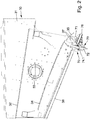
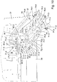
- FIG 1 shows a mobile crushing plant 10, as is typically used for crushing rock material or other mineral material.
- This Mobile crushing plant 10 has a machine chassis which is supported by two running gear designed as chain drives.
- the crushing plant 10 is equipped with a filling unit 20, which is usually designed as a funnel-shaped feed unit.
- the crushing plant 10 can be filled with the material to be shredded via this filling unit 20.
- the filling unit 20 has a conveyor on the bottom, in particular a grate gutter or, as in the present case, a conveyor belt.
- the material to be comminuted is conveyed to a sieving unit 30 via this conveying device.
- a vibration exciter 38 is assigned to the sieving unit 30 and can be designed as an eccentric drive. With this vibration exciter 38, the sieving unit 30 can be set in vibration in order to subject the conveyed material to a sieving process.
- the vibration exciter 38 not only vibrates the sieving unit 30 for sieving purposes, but in connection with the inclined arrangement of the individual sieve decks, a transport effect is also achieved, as in the case of a vibration conveyor.
- the crushing unit 40 is designed in the form of a jaw crusher. This crushing unit 40 has two crushing jaws which form a converging gap. The material to be shredded is conveyed into this gap area.
- the crushing unit 40 has a fixed crushing jaw and a movable crushing jaw. The movable crushing jaw is driven by an eccentric drive 41.
- the coarse rock material is broken in the converging gap. At the bottom, the broken and crushed rock material leaves the crushing unit 40 and falls onto a crusher discharge conveyor 60 due to gravity.
- the crusher discharge conveyor 60 is designed as an endlessly rotating conveyor belt. The crushed rock material is discharged via the crusher discharge conveyor 60 and piled up next to the crushing plant 10.
- the material coming from the filling unit 20 is passed through a sieve 32 (eg top sieve deck) in the sieving unit 30.
- a sieve 32 eg top sieve deck
- rock parts which, because of their size, do not have to be sent through the crushing unit 40, since they already have a size which corresponds approximately to the size of the rock which is broken by the crushing unit 40.
- a part of this sifted rock fraction is fed directly onto the crusher discharge conveyor 60, namely in the bypass past the crusher unit 40.
- Below the sieve 32 there is now another sieve deck 34 in the sieving unit 30. This screen deck 34 screens a further, fine fraction from the material that has already been screened.
- the sieve unit 30 has two side walls 31 which are arranged at a distance from one another.
- the conveying area for the rock material is formed between the two side walls 31.
- the illustration shows that at least one of the side walls 31 has a receptacle 33 for the vibration exciter 38.
- the vibration energy of the vibration exciter 38 can thus be introduced into the side wall 31.
- a different arrangement of the vibration exciter 38 is also conceivable, but it should be provided that the vibration energy from the vibration exciter 38 is introduced into the sieving unit 30 so that the sieving unit 30 vibrates with the frequency and amplitude of the vibration exciter 38.
- the sieve 32 is held between the two side walls 31 in the upper region of the sieve unit 30.
- the sieve deck 34 is arranged below the sieve 32.
- a conveying area results between the screen 32 and the screen deck 34.
- a conveying area is delimited above the sieve 32 by means of the two side walls 31 and the sieve 32.
- a further conveying area results below the screen deck 34.
- This conveyor area is delimited on the bottom side by a conveyor trough 36.
- the conveyor trough 36 can be designed as a limp component, for example made of rubber or plastic, the longitudinal extent of the conveyor trough 36 extending from the left side of the sieving unit 30 to the adjustable conveyor unit 70.
- the screen deck 34 can be extended by means of a discharge surface 35.
- the discharge surface 35 adjoins the screen deck 34 in the conveying direction in the form of a descending step, so that no barrier arises in the conveying direction.
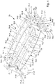
- the adjustable conveyor unit 70 has a flap 72 and a conveyor element 76.
- the flap 72 can be pivoted about a pivot axis 74.1.
- an operating position is shown in which the flap 72 is in a pivoted conveying position.
- the fine fraction fraction screened out from the screen deck 34 is fed onto the discharge belt 50 by means of the flap 72.
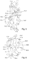
- Figure 3 shows a further operating position of the flap 72, which represents the bypass position. In this pivoted position, the screened fine rock material coming from the conveyor trough 36 is guided onto the conveyor element 76 via the flap 72. The fine rock material then falls from the conveying element 76 onto the crusher discharge conveyor 60.
- the side walls 31 have screw receptacles 37 in the region of the adjustable conveyor unit 70. These are used for fastening the adjustable conveyor unit 70 to the side walls 31 by means of fastening screws 71.6.
- the adjustable conveyor unit 70 can thus be attached to the sieve unit 30.
- the conveyor unit 70 is preferably flanged to the sieve unit 30 by means of flange sections, as will be explained in more detail below.
- the adjustable conveyor unit 70 has two lateral fastening sections 71, which can be designed as sheet metal sections. Both the flap 72 and the conveying element 76 are arranged between the two fastening sections 71.
- the conveyor unit 70 is flanged to the sieve unit 30.
- flange sections 71.7, 71.8 are formed on the opposite side walls 31 of the sieve unit 30 and on the fastening sections 71 of the conveyor unit 70.
- the flange sections 71.7, 71.8 are in detail in the Figures 5 and 6 shown.
- the flap 72 can be formed by a sheet metal section 72.4 as a stamped and bent part. It has a central region 72.1, to which bends 72.2 are connected on both sides. Facing the center area 72.1, the bends 72.2 have bends 72.3. A trough-shaped geometry of the conveying trough 36 is simulated via the laterally set bends 72.2 and the central region 72.1.
- a support structure 73 is arranged below the flap 72. This support structure 73 has interconnected longitudinal struts 73.1 and cross struts 73.2, 73.3. The flap 72 is underpinned with the support structure 73, so that a stable, lightweight construction is realized.
- a material section 72.5 made of a pliable material for example in the form of a material web made of rubber or plastic.
- This embodiment is, for example, in the Figures 5 and 7 to 10 shown.
- the material section 72.5 can be clamped in the manner of a drum covering on the outer sides of the folds 72.3, so that the material section 72.5, especially in the middle area 72.1 and in the area of the bends 72.2, can be set into particularly strong vibrations when the conveyor unit 70 is together with the sieve unit 30 swings in order to prevent clumping and jamming of the conveyed material arranged thereon.
- the support structure 73 it is also conceivable that at least one stiffening element (not shown) is present in or on the material section 72.5.
- the stiffening element or elements can be made of plastic or metal, for example.
- the flap 72 can be brought into the desired shape and held in this shape by the stiffening element or elements.
- the central region 72.1 and the bends 72.2 which adjoin it laterally can be formed by the support structure 73 and / or the stiffening element or elements in the flap 72, so that they emulate the trough-like geometry of the conveyor trough 36.
- the longitudinal struts 73.1 can have openings through which a profile section 74 is passed.
- the profile section 74 can be fixed to the longitudinal struts 73.1, for example welded.
- the profile section 74 forms with its central longitudinal axis the pivot axis 74.1 of the flap 72.
- bearing sections 75.1 of a bearing 75 are attached to the profile section 74, as is the case here Figure 5 reveals.
- the bearing sections 75.1 can, like shown to be formed by circular disks.
- the bearing sections 75.1 are welded to the ends of the profile section 74 or fastened in a rotationally fixed manner in some other way.
- Locking sections 77.1, 77.2 with locking receptacle 77.3 can be attached either to the bearing sections 75.1 or the support structure 73 or the flap 72.
- each of the bearing sections 75.1 is assigned two clamping sections 80.1, 80.2.
- clamping sections 80.1, 80.2 are held together by means of screws 80.3 and nuts 80.4. If the screws 80.3 or nuts 80.4 are loosened to such an extent that the clamping sections 80.1, 80.2 are held together, but their inner circumference does not abut the outer circumference of the bearing sections 75.1, the clamping sections 80.1, 80.2 are located in a so-called. Bearing position and form inventory for the warehouse sections 75.1.
- the flap 72 can be rotated about the pivot axis 74.1 into one of the pivot positions.
- the clamping sections 80.1, 80.2 reach a securing position in which an inner circumference formed by the clamping sections 80.1, 80.2 is reduced, so that the clamping sections 80.1, 80.2 have a clamping effect on the bearing sections 75.1 and the flap 72 in the swivel position relative to the conveyor unit 70.
- the clamping sections 80.1, 80.2 thus form bearing mounts with adjustable bearing play.
- the bearing play can be reduced to a minimum in the securing position, so that knocking out of the bearings 75 during the operational use of the crushing plant 10 is practically impossible.
- an additional securing of the flap 72 can be provided.
- the additional securing takes place, for example, by using positioning elements 71.5 which are brought into engagement with the locking receptacles 77.3 in the respective pivoted position.
- the positioning elements 71.5 are designed as fastening screws which are inserted through screw receptacles 71.3, 71.4 of the fastening sections 71 and are screwed into the locking receptacles 77.3 designed as threaded receptacles.
- one or more, preferably two, positioning elements 71.5 secure the assignment of the flap 72 to the fastening sections 71 for each swivel position.
- the bearing sections 75.1 can be fixed by means of the releasable clamping sections 80.1, 80.2 in a pivoted position of the flap 72 relative to the conveyor unit 70 or the fastening sections 71, so that the flap 72 is held in a rotationally fixed manner relative to the conveyor unit 70.
- additional securing of the bearing sections 75.1 by means of the locking sections 77.1, 77.2 with the locking receptacles 77.3 and the positioning elements 71.5 can be dispensed with.
- each of the bearing sections 75.1 is assigned two clamping sections 80.1, 80.2, a first clamping section 80.1 of a bearing 75 being fastened to one of the fastening sections 71 and designed to receive the bearing section 75.1, and the other clamping section 80.2 on one of the First clamping section 80.1 opposite side of the bearing section 75.1 is arranged and releasably attachable to the first clamping section 75.1, so that the bearing section 75.1 can be clamped between the two clamping sections 80.1, 80.2 in their securing position.
- the bearing section 75.1 is in a pivoted position of the flap 72 relative to the Conveyor unit 70 can be fixed and the flap 72 is rotatably held in the pivoting position relative to the conveyor unit 70.
- This clamping securing of the flap 72 relative to the fastening sections 71 has proven to be particularly suitable for the large vibrations occurring during the operation of the crushing plant 10.
- the first clamping section 80.1 is fastened to the fastening section 71, for example by means of welding.
- the second clamping section 80.2 can, for example, be detachably fastened to the first clamping section 80.1 by means of the screws 80.3.
- the screws 80.3 can be passed through corresponding openings in the clamping sections 80.1, 80.2 and secured with the nuts 80.4.
- a distance between the clamping sections 80.1, 80.2 can be reduced in the manner of brackets or clamps. In this way, the bearing sections 75.1 can be clamped between the clamping sections 80.1, 80.2.
- the bearing sections 75.1 have a substantially circular outer circumference and the clamping sections 80.1, 80.2 each have a circular arc-shaped inner circumference.
- the inner circumference of the clamping sections 80.1, 80.2 can also comprise a plurality of flat segments which, strung together, form an approximately circular arc-shaped inner circumference. In this way, the clamping sections 80.1, 80.2 can rest on the bearing sections 75.1 over a large area.
- At least one of the bearing sections 75.1 has an actuating element 75.2, which is non-rotatably connected to the bearing section 75.1 and thus to the flap 72.
- the actuating element 75.2 can be formed, for example, by a hexagon.
- the actuating element 75.2 can be accessed with a tool.
- the actuating element 75.2 can be adjusted with the tool and with it the flap 72 in order to pivot it between the bypass position and the conveying position.
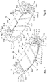
- the conveying element 76 is also fastened to the two fastening sections 71.
- the conveying element 76 can consist of a sheet metal section 78.8 as a stamped and bent part be made. It has a central region 76.1, to which bends 76.2 are connected laterally. Facing the central area 76.1, bends 76.3 are bent away from the bends 76.2.
- the bevels 76.3 have fastening receptacles 76.6, such as Figure 4 reveals.
- the conveying element 76 can then be connected to the fastening sections 71 by means of suitable fastening elements, for example screws 76.7.
- the conveyor element 76 therefore fixes the two fastening sections 71 at the desired distance from one another. With the central region 76.1 and the two bends 76.2, the conveying element 76 simulates the trough-shaped geometry of the flap 72 or the conveying trough 36.
- a material section 76.9 made of a pliable material for example a material web made of rubber or plastic, can rest at least in some areas.
- This embodiment is, for example, in the Figures 9 and 10 shown.
- the material section 76.9 can be clamped in the manner of a drum covering on the outer sides of the folds 76.3, so that the material section 76.9, especially in the central area 76.1 and in the area of the bends 76.2, can be set into particularly strong vibrations when the conveyor unit 70 is together with the sieve unit 30 swings in order to prevent clumping and jamming of the conveyed material arranged thereon.
- the material section 76.9 is provided from the limp material instead of the sheet metal section 76.8 and rests directly on the support structure 76.4, 76.5 of the conveying element 76.
- the material web 76.9 is clamped and held on the outside at the folds 76.3 and lies only in the middle area 76.1 and in the area of the bends 76.2 on the support structure 76.4, 76.5.
- the support structure 76.4, 76.5 or additionally it is also conceivable that at least one stiffening element (not shown) is present in or on the material section 76.9.
- the stiffening element or elements can be made of plastic or metal, for example.
- the conveying element 76 can be brought into the desired shape and held in this shape.
- the central region 76.1 and the bends 76.2 which adjoin it laterally can be formed by the support structure 76.4, 76.5 and / or the stiffening element or elements in the conveying element 76, so that they emulate the trough-like geometry of the flap 72 or the conveying trough 36.
- connection between the clamping sections 80.1, 80.2 is released in order to release the clamping holder of the bearing sections 75.1.
- a suitable tool is then brought into engagement with the actuating element 75.2.
- the flap 72 can then be rotated until it is in the Figures 2 and 8th shown pivot position reached.
- the released clamping sections 80.1, 80.2 serve as bearing mounts.
- the conveying path between the conveying trough 36 and the conveying element 76 is interrupted.
- the material stream coming from the conveyor trough 36 is now passed directly onto the discharge belt 50.
- the flap 72 blocks the path between the conveying trough 36 and the conveying element 76 and, for this purpose, also protrudes a little above these components.
Landscapes
- Engineering & Computer Science (AREA)
- Food Science & Technology (AREA)
- Combined Means For Separation Of Solids (AREA)
- Crushing And Pulverization Processes (AREA)
Claims (15)
- Installation de traitement, notamment installation de broyage (10), en particulier broyeur de roche, comprenant une unité de remplissage (20) pouvant être remplie d'un matériau à broyer,
dans le sens de transport après l'unité de remplissage (20) ou dans l'unité de remplissage (20), est disposée une unité de tamisage (30),
l'unité de tamisage (30) pouvant être amenée à osciller à l'aide d'un générateur de vibrations (38),
par l'intermédiaire de l'unité de tamisage (30), une première partie du matériau fourni étant acheminée vers une unité de traitement, en particulier un groupe de broyage (40) et une autre partie du matériau fourni étant tamisée dans l'unité de tamisage (30),
la partie tamisée du produit pouvant être acheminée au moyen d'un volet (72) d'une unité de transport (70) réglable autour d'un axe de pivotement (74.1), sélectivement dans une partie de dérivation sur l'unité de traitement, en particulier sur le groupe de broyage (40), devant un dispositif de transport, en particulier un transporteur de déchargement de broyeur (60) ou est déchargée dans une position de transport au moyen d'un transporteur (50) depuis une zone de travail de l'installation de traitement,
des sections de palier (75.1) d'un palier (75) couplées sur des côtés opposés du volet (72) étant montées à rotation sur l'unité de transport (70),
caractérisée en ce qu'
au moins une section de serrage détachable (80.1, 80.2) est associée à au moins une des sections de palier (75.1), qui agit par serrage sur la section de palier associée (75.1) et la fixe dans une position de pivotement du volet (72) par rapport à l'unité de transport (70), de sorte que le volet (72) dans la position de pivotement soit maintenu solidaire en rotation par rapport à l'unité de transport (70). - Installation de traitement selon la revendication 1,
caractérisée en ce qu'
le volet (72) présente une section profilée (74) dont l'axe central forme l'axe de pivotement (74.1) et à ses extrémités longitudinales sont couplés les sections (75.1) du palier (75). - Installation de traitement selon la revendication 1 ou 2,
caractérisée en ce qu'
l'unité de transport réglable (70) présente deux sections de fixation (71) espacées l'une de l'autre, dans chacune desquelles un passage (71.2) est formé pour l'une des sections de palier (75.1), de sorte que le volet (72) soit maintenu en pivotement entre les sections de fixation (71) autour de l'axe de pivotement (74.1), les sections de fixation (71) étant fixées à l'unité de tamisage (30). - Installation de traitement selon la revendication 3,
caractérisée en ce qu'
les sections de fixation (71) sont raccordées sur les parois latérales opposées (31) de l'unité de tamisage (30) par les sections de bride (71.7, 71.8) formées sur les parois latérales (31) et les sections de fixation (71). - Installation de traitement selon la revendication 3 ou 4,
caractérisée en ce qu'
deux sections de serrage (80.1, 80.2) sont associées à ladite section de palier (75.1), une première section de serrage (80.1) étant fixée à l'une des sections de fixation (71) et conçue pour loger la section de palier (75.1) et l'autre section de serrage (80.2) étant disposée sur un côté de la section de palier (75.1) en regard de la première section de serrage (80.1) et peut être fixée amovible sur la première section de serrage (80.1) de sorte que la section de palier (75.1) puisse être bloquée par rapport à l'unité de transport (70) dans une position de pivotement du volet (72) et que le volet (72) soit maintenu solidaire en rotation dans la position de pivotement par rapport à l'unité de transport (70). - Installation de traitement selon la revendication 5,
caractérisée en ce qu'
les sections de serrage (80.1, 80.2) associées chacune à une des sections de palier (75.1) sont fixées les unes aux autres au moyen de vis (80.3) et la section de palier (75.1) est serrée par les vis (80.3) entre les sections de serrage (80.1, 80.2), de sorte que le volet (72) soit maintenu solidaire en rotation dans la position de pivotement par rapport à l'unité de transport (70). - Installation de traitement selon l'une des revendications 1 à 6,
caractérisée en ce qu'
ladite section de palier (75.1) a une circonférence extérieure sensiblement circulaire et ladite section de serrage (80.1, 80.2) a une circonférence intérieure arquée. - Installation de traitement selon l'une des revendications 1 à 7,
caractérisée en ce qu'
le volet (72) présente une région centrale (72.1) contiguë des deux côtés à des courbures (72.2) transversalement à la direction de transport et en ce que l'unité de tamisage (30) présente un canal de transport (36) qui est, au moins à certains endroits, constitué d'un composant souple, par exemple une bande de caoutchouc, sur lequel le volet (72) est appliqué, sa face inférieure étant en position de dérivation. - Installation de traitement selon l'une des revendications 1 à 8,
caractérisée en ce qu'
le volet (72) est étayé au moyen d'une structure de support (73) formée par des entretoises longitudinales (73.1) et des entretoises transversales (73.2, 73.3). - Installation de traitement selon l'une des revendications 1 à 9,
caractérisée en ce qu'
l'unité de transport réglable (70) présente un élément de transport (76) dans la direction de transport derrière le volet (72) qui, dans la position de dérivation du volet (72), est adjacent à une région de transport du volet (72). - Installation de traitement selon la revendication 10,
caractérisée en ce qu'
l'élément de transport (76) est étayé au moyen d'une structure de support qui est formée par une ou plusieurs entretoises de support, en particulier des entretoises transversales (76.4) et/ou des entretoises longitudinales (76.5). - Installation de traitement selon la revendication 9 ou 11,
caractérisée en ce qu'
le volet (72) et/ou l'élément de transport (76) présentent une section en tôle (72.4 ; 76.8), qui est de préférence étayée sur sa face inférieure par la structure de support (73 ; 73.1, 73.2, 73.3 ; 76.4, 76.5). - Installation de traitement selon la revendication 9 ou 11,
caractérisée en ce qu'
le volet (72) et/ou l'élément de transport (76) présentent une section de matériau (72.5 ; 76.9) constituée d'un matériau souple, en particulier de caoutchouc ou de plastique, qui est de préférence étayé sur sa face inférieure par la structure de support (73 ; 73.1, 73.2, 73.3 ; 76.4, 76.5) et/ou en ce qu'au moins un élément raidisseur est présent dans ou sur la section de matériau (72.5 ; 76.9). - Installation de traitement selon la revendication 12,
caractérisée en ce qu'
le volet (72) et/ou l'élément de transport (76) présentent une section de matériau (72.5 ; 76.9) constituée d'un matériau souple, en particulier de caoutchouc ou de plastique, qui est étayée sur sa face inférieure par la section en tôle (72.4 ; 76.8). - Installation de traitement selon l'une des revendications 1 à 14,
caractérisée en ce qu'
sur le volet (72) une ou plusieurs sections de blocage (77.1, 77.2) sont couplées à au moins un logement de blocage (77.3) qui peuvent être bloquées en position de dérivation et/ou en position de transport sur des éléments de fixation fixes (71.3).
Applications Claiming Priority (2)
| Application Number | Priority Date | Filing Date | Title |
|---|---|---|---|
| DE102018106177.3A DE102018106177A1 (de) | 2018-03-16 | 2018-03-16 | Aufbereitungsanlage |
| PCT/EP2019/051707 WO2019174802A1 (fr) | 2018-03-16 | 2019-01-24 | Installation de traitement |
Publications (2)
| Publication Number | Publication Date |
|---|---|
| EP3565670A1 EP3565670A1 (fr) | 2019-11-13 |
| EP3565670B1 true EP3565670B1 (fr) | 2020-02-12 |
Family
ID=65351998
Family Applications (1)
| Application Number | Title | Priority Date | Filing Date |
|---|---|---|---|
| EP19703956.3A Active EP3565670B1 (fr) | 2018-03-16 | 2019-01-24 | Installation de traitement |
Country Status (5)
| Country | Link |
|---|---|
| US (1) | US11325132B2 (fr) |
| EP (1) | EP3565670B1 (fr) |
| CN (1) | CN111788004A (fr) |
| DE (1) | DE102018106177A1 (fr) |
| WO (1) | WO2019174802A1 (fr) |
Families Citing this family (2)
| Publication number | Priority date | Publication date | Assignee | Title |
|---|---|---|---|---|
| DE102022118032B3 (de) * | 2022-07-19 | 2023-08-10 | Kleemann Gmbh | Mobile Gesteinsverarbeitungsvorrichtung mit verbesserter Planung einer diskontinuierlichen Materialaufgabe |
| DE102022118036B3 (de) | 2022-07-19 | 2023-08-10 | Kleemann Gmbh | Gesteinsverarbeitungsvorrichtung mit verbesserter Planung des Orts einer Materialaufgabe innerhalb eines Materialpuffers |
Family Cites Families (17)
| Publication number | Priority date | Publication date | Assignee | Title |
|---|---|---|---|---|
| US3409235A (en) * | 1968-11-05 | John N Quinn | Portable crushing plant | |
| US1673465A (en) * | 1927-07-05 | 1928-06-12 | Wilson L Mclaughlin | Pulverizing machine |
| US2155393A (en) * | 1933-06-16 | 1939-04-25 | Pennsylvania Crusher Co | Crusher frame |
| US2317852A (en) * | 1941-01-16 | 1943-04-27 | Baldwin Locomotive Works | Elevator |
| US2962983A (en) * | 1956-09-25 | 1960-12-06 | Unitcast Corp | Railway hopper car door locks |
| US3073536A (en) * | 1959-06-22 | 1963-01-15 | Johnson Welding & Equipment Co | Portable crushing plant |
| US3620350A (en) * | 1969-12-11 | 1971-11-16 | Mcdowell Wellman Eng Co | Bulk material flow control apparatus |
| CA1042404A (fr) | 1974-07-02 | 1978-11-14 | John N. Quinn | Installation de concassage |
| US4105544A (en) * | 1977-04-26 | 1978-08-08 | Stevick Ronald A | Gravel processing system |
| CN201889289U (zh) * | 2010-11-12 | 2011-07-06 | 中国瑞林工程技术有限公司 | 手动转换漏斗 |
| CA2817300A1 (fr) * | 2012-06-21 | 2013-12-21 | Laitram, L.L.C. | Organe d'alimentation traversant pour un appareil de traitement |
| US9205459B2 (en) * | 2012-08-28 | 2015-12-08 | Terex Usa, Llc | Vibrating screen deck deflector systems and methods |
| CN203778134U (zh) * | 2014-04-29 | 2014-08-20 | 刘荆宇 | 多级分筛环锤调节式破碎机 |
| CN205128048U (zh) * | 2015-10-15 | 2016-04-06 | 广元壮牛农牧科技有限公司 | 一种饲料破碎机 |
| CN205363143U (zh) * | 2015-12-18 | 2016-07-06 | 天津市庆鑫祥科技发展有限公司 | 一种户外管道焊接工装 |
| CH712095A1 (de) * | 2016-02-04 | 2017-08-15 | Ferag Ag | Laufwagen für ein Fördersystem und Fördersystem mit Laufwagen. |
| AT518405B1 (de) * | 2016-07-19 | 2017-10-15 | Man Truck & Bus Österreich Gesmbh | Fahrerhauslagerung für ein kippbares Fahrerhaus eines Nutzfahrzeugs |
-
2018
- 2018-03-16 DE DE102018106177.3A patent/DE102018106177A1/de not_active Withdrawn
-
2019
- 2019-01-24 CN CN201980016392.1A patent/CN111788004A/zh active Pending
- 2019-01-24 WO PCT/EP2019/051707 patent/WO2019174802A1/fr not_active Ceased
- 2019-01-24 US US16/971,458 patent/US11325132B2/en active Active
- 2019-01-24 EP EP19703956.3A patent/EP3565670B1/fr active Active
Non-Patent Citations (1)
| Title |
|---|
| None * |
Also Published As
| Publication number | Publication date |
|---|---|
| WO2019174802A1 (fr) | 2019-09-19 |
| EP3565670A1 (fr) | 2019-11-13 |
| CN111788004A (zh) | 2020-10-16 |
| DE102018106177A1 (de) | 2019-09-19 |
| US11325132B2 (en) | 2022-05-10 |
| US20210031209A1 (en) | 2021-02-04 |
Similar Documents
| Publication | Publication Date | Title |
|---|---|---|
| DE102012110361B4 (de) | Vorrichtung zum Sortieren | |
| EP3714981B1 (fr) | Installation de traitement, en particulier installation de concassage, en particulier concasseur | |
| EP3630361B1 (fr) | Installation de traitement | |
| EP1638702A2 (fr) | Tamiseur a tambour | |
| DE202008003553U1 (de) | Schwingsiebmaschine | |
| DE19601262A1 (de) | Trockensiebsystem mit Fördereinrichtung zur Trennung von Sand & Kies | |
| EP4308314B1 (fr) | Appareil de séparation de matériau d'alimentation | |
| EP3565670B1 (fr) | Installation de traitement | |
| WO2003066219A1 (fr) | Broyeur a machoires pourvu d'un arbre de commande traversant | |
| EP1577023B1 (fr) | Machine à tamiser pour tambours de diamètres différents | |
| EP3750632B1 (fr) | Unité de distribution pour une installation de traitement, en particulier une installation de broyage ou de criblage | |
| EP3228393A1 (fr) | Dispositif de tamisage | |
| DE102018112902B4 (de) | Abstreifelement zum Abstreifen von außen an einer Hohltrommel einer Vorrichtung zum Trennen von miteinander vermischten Stoffen unterschiedlicher Fließfähigkeit anliegenden Stoffresten sowie Vorrichtung mit einem solchen Abstreifelement | |
| DE4210881A1 (de) | Vibrationssiebmaschine, insbesondere zum Klassieren von sehr unterschiedlichem Aufbereitungsgut wie Haldenmaterial aus Müll und/oder Bauschuttdeponien | |
| DE3834381A1 (de) | Vorrichtung zum zerkleinern und aufbereiten von grosskoernigem material | |
| EP3760322A1 (fr) | Dispositif de transport de dosage destiné au transport et au dosage d'un mélange solide | |
| DE102021119918B4 (de) | Aufbereitungsanlage | |
| DE10053845A1 (de) | Verbesserungen für Siebkästen | |
| AT398392B (de) | Siebvorrichtung, insbesondere zum sortieren von abfallmaterial | |
| DE2701341A1 (de) | Siebmaschine zur trennung von siebschwierigen materialien | |
| DE3219289C2 (de) | Zerkleinerungsvorrichtung | |
| DE102024120878B3 (de) | Siebmaschine | |
| DE3403818A1 (de) | Siebvorrichtung | |
| DE2757527A1 (de) | Vorrichtung zur verbesserung des fliessverhaltens von schwerfliessendem schuettgut | |
| DE102024135219A1 (de) | Brechersiebeinheit |
Legal Events
| Date | Code | Title | Description |
|---|---|---|---|
| STAA | Information on the status of an ep patent application or granted ep patent |
Free format text: STATUS: UNKNOWN |
|
| STAA | Information on the status of an ep patent application or granted ep patent |
Free format text: STATUS: THE INTERNATIONAL PUBLICATION HAS BEEN MADE |
|
| PUAI | Public reference made under article 153(3) epc to a published international application that has entered the european phase |
Free format text: ORIGINAL CODE: 0009012 |
|
| STAA | Information on the status of an ep patent application or granted ep patent |
Free format text: STATUS: REQUEST FOR EXAMINATION WAS MADE |
|
| 17P | Request for examination filed |
Effective date: 20190618 |
|
| AK | Designated contracting states |
Kind code of ref document: A1 Designated state(s): AL AT BE BG CH CY CZ DE DK EE ES FI FR GB GR HR HU IE IS IT LI LT LU LV MC MK MT NL NO PL PT RO RS SE SI SK SM TR |
|
| AX | Request for extension of the european patent |
Extension state: BA ME |
|
| GRAP | Despatch of communication of intention to grant a patent |
Free format text: ORIGINAL CODE: EPIDOSNIGR1 |
|
| STAA | Information on the status of an ep patent application or granted ep patent |
Free format text: STATUS: GRANT OF PATENT IS INTENDED |
|
| INTG | Intention to grant announced |
Effective date: 20191115 |
|
| GRAS | Grant fee paid |
Free format text: ORIGINAL CODE: EPIDOSNIGR3 |
|
| GRAA | (expected) grant |
Free format text: ORIGINAL CODE: 0009210 |
|
| STAA | Information on the status of an ep patent application or granted ep patent |
Free format text: STATUS: THE PATENT HAS BEEN GRANTED |
|
| AK | Designated contracting states |
Kind code of ref document: B1 Designated state(s): AL AT BE BG CH CY CZ DE DK EE ES FI FR GB GR HR HU IE IS IT LI LT LU LV MC MK MT NL NO PL PT RO RS SE SI SK SM TR |
|
| DAV | Request for validation of the european patent (deleted) | ||
| DAX | Request for extension of the european patent (deleted) | ||
| REG | Reference to a national code |
Ref country code: GB Ref legal event code: FG4D Free format text: NOT ENGLISH |
|
| REG | Reference to a national code |
Ref country code: CH Ref legal event code: EP Ref country code: CH Ref legal event code: NV Representative=s name: DENNEMEYER AG, CH |
|
| REG | Reference to a national code |
Ref country code: AT Ref legal event code: REF Ref document number: 1231389 Country of ref document: AT Kind code of ref document: T Effective date: 20200215 |
|
| REG | Reference to a national code |
Ref country code: IE Ref legal event code: FG4D Free format text: LANGUAGE OF EP DOCUMENT: GERMAN |
|
| REG | Reference to a national code |
Ref country code: DE Ref legal event code: R096 Ref document number: 502019000005 Country of ref document: DE |
|
| REG | Reference to a national code |
Ref country code: FI Ref legal event code: FGE |
|
| REG | Reference to a national code |
Ref country code: SE Ref legal event code: TRGR |
|
| PG25 | Lapsed in a contracting state [announced via postgrant information from national office to epo] |
Ref country code: NO Free format text: LAPSE BECAUSE OF FAILURE TO SUBMIT A TRANSLATION OF THE DESCRIPTION OR TO PAY THE FEE WITHIN THE PRESCRIBED TIME-LIMIT Effective date: 20200512 Ref country code: RS Free format text: LAPSE BECAUSE OF FAILURE TO SUBMIT A TRANSLATION OF THE DESCRIPTION OR TO PAY THE FEE WITHIN THE PRESCRIBED TIME-LIMIT Effective date: 20200212 |
|
| REG | Reference to a national code |
Ref country code: LT Ref legal event code: MG4D |
|
| REG | Reference to a national code |
Ref country code: NL Ref legal event code: MP Effective date: 20200212 |
|
| PG25 | Lapsed in a contracting state [announced via postgrant information from national office to epo] |
Ref country code: HR Free format text: LAPSE BECAUSE OF FAILURE TO SUBMIT A TRANSLATION OF THE DESCRIPTION OR TO PAY THE FEE WITHIN THE PRESCRIBED TIME-LIMIT Effective date: 20200212 Ref country code: GR Free format text: LAPSE BECAUSE OF FAILURE TO SUBMIT A TRANSLATION OF THE DESCRIPTION OR TO PAY THE FEE WITHIN THE PRESCRIBED TIME-LIMIT Effective date: 20200513 Ref country code: BG Free format text: LAPSE BECAUSE OF FAILURE TO SUBMIT A TRANSLATION OF THE DESCRIPTION OR TO PAY THE FEE WITHIN THE PRESCRIBED TIME-LIMIT Effective date: 20200512 Ref country code: IS Free format text: LAPSE BECAUSE OF FAILURE TO SUBMIT A TRANSLATION OF THE DESCRIPTION OR TO PAY THE FEE WITHIN THE PRESCRIBED TIME-LIMIT Effective date: 20200612 Ref country code: LV Free format text: LAPSE BECAUSE OF FAILURE TO SUBMIT A TRANSLATION OF THE DESCRIPTION OR TO PAY THE FEE WITHIN THE PRESCRIBED TIME-LIMIT Effective date: 20200212 |
|
| PG25 | Lapsed in a contracting state [announced via postgrant information from national office to epo] |
Ref country code: NL Free format text: LAPSE BECAUSE OF FAILURE TO SUBMIT A TRANSLATION OF THE DESCRIPTION OR TO PAY THE FEE WITHIN THE PRESCRIBED TIME-LIMIT Effective date: 20200212 |
|
| PG25 | Lapsed in a contracting state [announced via postgrant information from national office to epo] |
Ref country code: SK Free format text: LAPSE BECAUSE OF FAILURE TO SUBMIT A TRANSLATION OF THE DESCRIPTION OR TO PAY THE FEE WITHIN THE PRESCRIBED TIME-LIMIT Effective date: 20200212 Ref country code: RO Free format text: LAPSE BECAUSE OF FAILURE TO SUBMIT A TRANSLATION OF THE DESCRIPTION OR TO PAY THE FEE WITHIN THE PRESCRIBED TIME-LIMIT Effective date: 20200212 Ref country code: CZ Free format text: LAPSE BECAUSE OF FAILURE TO SUBMIT A TRANSLATION OF THE DESCRIPTION OR TO PAY THE FEE WITHIN THE PRESCRIBED TIME-LIMIT Effective date: 20200212 Ref country code: ES Free format text: LAPSE BECAUSE OF FAILURE TO SUBMIT A TRANSLATION OF THE DESCRIPTION OR TO PAY THE FEE WITHIN THE PRESCRIBED TIME-LIMIT Effective date: 20200212 Ref country code: DK Free format text: LAPSE BECAUSE OF FAILURE TO SUBMIT A TRANSLATION OF THE DESCRIPTION OR TO PAY THE FEE WITHIN THE PRESCRIBED TIME-LIMIT Effective date: 20200212 Ref country code: PT Free format text: LAPSE BECAUSE OF FAILURE TO SUBMIT A TRANSLATION OF THE DESCRIPTION OR TO PAY THE FEE WITHIN THE PRESCRIBED TIME-LIMIT Effective date: 20200705 Ref country code: LT Free format text: LAPSE BECAUSE OF FAILURE TO SUBMIT A TRANSLATION OF THE DESCRIPTION OR TO PAY THE FEE WITHIN THE PRESCRIBED TIME-LIMIT Effective date: 20200212 Ref country code: EE Free format text: LAPSE BECAUSE OF FAILURE TO SUBMIT A TRANSLATION OF THE DESCRIPTION OR TO PAY THE FEE WITHIN THE PRESCRIBED TIME-LIMIT Effective date: 20200212 Ref country code: SM Free format text: LAPSE BECAUSE OF FAILURE TO SUBMIT A TRANSLATION OF THE DESCRIPTION OR TO PAY THE FEE WITHIN THE PRESCRIBED TIME-LIMIT Effective date: 20200212 |
|
| REG | Reference to a national code |
Ref country code: DE Ref legal event code: R097 Ref document number: 502019000005 Country of ref document: DE |
|
| PLBE | No opposition filed within time limit |
Free format text: ORIGINAL CODE: 0009261 |
|
| STAA | Information on the status of an ep patent application or granted ep patent |
Free format text: STATUS: NO OPPOSITION FILED WITHIN TIME LIMIT |
|
| 26N | No opposition filed |
Effective date: 20201113 |
|
| PG25 | Lapsed in a contracting state [announced via postgrant information from national office to epo] |
Ref country code: PL Free format text: LAPSE BECAUSE OF FAILURE TO SUBMIT A TRANSLATION OF THE DESCRIPTION OR TO PAY THE FEE WITHIN THE PRESCRIBED TIME-LIMIT Effective date: 20200212 |
|
| PG25 | Lapsed in a contracting state [announced via postgrant information from national office to epo] |
Ref country code: MC Free format text: LAPSE BECAUSE OF FAILURE TO SUBMIT A TRANSLATION OF THE DESCRIPTION OR TO PAY THE FEE WITHIN THE PRESCRIBED TIME-LIMIT Effective date: 20200212 |
|
| PG25 | Lapsed in a contracting state [announced via postgrant information from national office to epo] |
Ref country code: LU Free format text: LAPSE BECAUSE OF NON-PAYMENT OF DUE FEES Effective date: 20210124 |
|
| REG | Reference to a national code |
Ref country code: BE Ref legal event code: MM Effective date: 20210131 |
|
| PG25 | Lapsed in a contracting state [announced via postgrant information from national office to epo] |
Ref country code: IE Free format text: LAPSE BECAUSE OF NON-PAYMENT OF DUE FEES Effective date: 20210124 |
|
| PG25 | Lapsed in a contracting state [announced via postgrant information from national office to epo] |
Ref country code: BE Free format text: LAPSE BECAUSE OF NON-PAYMENT OF DUE FEES Effective date: 20210131 |
|
| PG25 | Lapsed in a contracting state [announced via postgrant information from national office to epo] |
Ref country code: CY Free format text: LAPSE BECAUSE OF FAILURE TO SUBMIT A TRANSLATION OF THE DESCRIPTION OR TO PAY THE FEE WITHIN THE PRESCRIBED TIME-LIMIT Effective date: 20200212 |
|
| PG25 | Lapsed in a contracting state [announced via postgrant information from national office to epo] |
Ref country code: HU Free format text: LAPSE BECAUSE OF FAILURE TO SUBMIT A TRANSLATION OF THE DESCRIPTION OR TO PAY THE FEE WITHIN THE PRESCRIBED TIME-LIMIT; INVALID AB INITIO Effective date: 20190124 |
|
| PG25 | Lapsed in a contracting state [announced via postgrant information from national office to epo] |
Ref country code: SI Free format text: LAPSE BECAUSE OF FAILURE TO SUBMIT A TRANSLATION OF THE DESCRIPTION OR TO PAY THE FEE WITHIN THE PRESCRIBED TIME-LIMIT Effective date: 20200212 |
|
| PG25 | Lapsed in a contracting state [announced via postgrant information from national office to epo] |
Ref country code: MK Free format text: LAPSE BECAUSE OF FAILURE TO SUBMIT A TRANSLATION OF THE DESCRIPTION OR TO PAY THE FEE WITHIN THE PRESCRIBED TIME-LIMIT Effective date: 20200212 |
|
| PG25 | Lapsed in a contracting state [announced via postgrant information from national office to epo] |
Ref country code: TR Free format text: LAPSE BECAUSE OF FAILURE TO SUBMIT A TRANSLATION OF THE DESCRIPTION OR TO PAY THE FEE WITHIN THE PRESCRIBED TIME-LIMIT Effective date: 20200212 |
|
| PG25 | Lapsed in a contracting state [announced via postgrant information from national office to epo] |
Ref country code: MT Free format text: LAPSE BECAUSE OF FAILURE TO SUBMIT A TRANSLATION OF THE DESCRIPTION OR TO PAY THE FEE WITHIN THE PRESCRIBED TIME-LIMIT Effective date: 20200212 |
|
| REG | Reference to a national code |
Ref country code: CH Ref legal event code: U11 Free format text: ST27 STATUS EVENT CODE: U-0-0-U10-U11 (AS PROVIDED BY THE NATIONAL OFFICE) Effective date: 20260201 |
|
| PGFP | Annual fee paid to national office [announced via postgrant information from national office to epo] |
Ref country code: SE Payment date: 20260121 Year of fee payment: 8 |
|
| PGFP | Annual fee paid to national office [announced via postgrant information from national office to epo] |
Ref country code: GB Payment date: 20260122 Year of fee payment: 8 |
|
| PGFP | Annual fee paid to national office [announced via postgrant information from national office to epo] |
Ref country code: DE Payment date: 20260120 Year of fee payment: 8 |
|
| PGFP | Annual fee paid to national office [announced via postgrant information from national office to epo] |
Ref country code: AT Payment date: 20260119 Year of fee payment: 8 |
|
| PGFP | Annual fee paid to national office [announced via postgrant information from national office to epo] |
Ref country code: FI Payment date: 20260120 Year of fee payment: 8 Ref country code: IT Payment date: 20260130 Year of fee payment: 8 |
|
| PGFP | Annual fee paid to national office [announced via postgrant information from national office to epo] |
Ref country code: FR Payment date: 20260121 Year of fee payment: 8 |
|
| PGFP | Annual fee paid to national office [announced via postgrant information from national office to epo] |
Ref country code: CH Payment date: 20260201 Year of fee payment: 8 |