EP3566733B1 - Medikamentenverabreichungsvorrichtung - Google Patents
Medikamentenverabreichungsvorrichtung Download PDFInfo
- Publication number
- EP3566733B1 EP3566733B1 EP19181670.1A EP19181670A EP3566733B1 EP 3566733 B1 EP3566733 B1 EP 3566733B1 EP 19181670 A EP19181670 A EP 19181670A EP 3566733 B1 EP3566733 B1 EP 3566733B1
- Authority
- EP
- European Patent Office
- Prior art keywords
- rotator
- medicament
- contactor
- housing
- distal
- Prior art date
- Legal status (The legal status is an assumption and is not a legal conclusion. Google has not performed a legal analysis and makes no representation as to the accuracy of the status listed.)
- Active
Links
Images





Classifications
-
- A—HUMAN NECESSITIES
- A61—MEDICAL OR VETERINARY SCIENCE; HYGIENE
- A61M—DEVICES FOR INTRODUCING MEDIA INTO, OR ONTO, THE BODY; DEVICES FOR TRANSDUCING BODY MEDIA OR FOR TAKING MEDIA FROM THE BODY; DEVICES FOR PRODUCING OR ENDING SLEEP OR STUPOR
- A61M5/00—Devices for bringing media into the body in a subcutaneous, intra-vascular or intramuscular way; Accessories therefor, e.g. filling or cleaning devices, arm rests
- A61M5/178—Syringes
- A61M5/20—Automatic syringes, e.g. with automatically actuated piston rod, with automatic needle injection, filling automatically
- A61M5/2033—Spring-loaded one-shot injectors with or without automatic needle insertion
-
- A—HUMAN NECESSITIES
- A61—MEDICAL OR VETERINARY SCIENCE; HYGIENE
- A61M—DEVICES FOR INTRODUCING MEDIA INTO, OR ONTO, THE BODY; DEVICES FOR TRANSDUCING BODY MEDIA OR FOR TAKING MEDIA FROM THE BODY; DEVICES FOR PRODUCING OR ENDING SLEEP OR STUPOR
- A61M5/00—Devices for bringing media into the body in a subcutaneous, intra-vascular or intramuscular way; Accessories therefor, e.g. filling or cleaning devices, arm rests
- A61M5/178—Syringes
- A61M5/31—Details
- A61M5/3146—Priming, e.g. purging, reducing backlash or clearance
-
- A—HUMAN NECESSITIES
- A61—MEDICAL OR VETERINARY SCIENCE; HYGIENE
- A61M—DEVICES FOR INTRODUCING MEDIA INTO, OR ONTO, THE BODY; DEVICES FOR TRANSDUCING BODY MEDIA OR FOR TAKING MEDIA FROM THE BODY; DEVICES FOR PRODUCING OR ENDING SLEEP OR STUPOR
- A61M5/00—Devices for bringing media into the body in a subcutaneous, intra-vascular or intramuscular way; Accessories therefor, e.g. filling or cleaning devices, arm rests
- A61M5/178—Syringes
- A61M5/20—Automatic syringes, e.g. with automatically actuated piston rod, with automatic needle injection, filling automatically
- A61M2005/2006—Having specific accessories
- A61M2005/2013—Having specific accessories triggering of discharging means by contact of injector with patient body
-
- A—HUMAN NECESSITIES
- A61—MEDICAL OR VETERINARY SCIENCE; HYGIENE
- A61M—DEVICES FOR INTRODUCING MEDIA INTO, OR ONTO, THE BODY; DEVICES FOR TRANSDUCING BODY MEDIA OR FOR TAKING MEDIA FROM THE BODY; DEVICES FOR PRODUCING OR ENDING SLEEP OR STUPOR
- A61M5/00—Devices for bringing media into the body in a subcutaneous, intra-vascular or intramuscular way; Accessories therefor, e.g. filling or cleaning devices, arm rests
- A61M5/178—Syringes
- A61M5/20—Automatic syringes, e.g. with automatically actuated piston rod, with automatic needle injection, filling automatically
- A61M2005/2073—Automatic syringes, e.g. with automatically actuated piston rod, with automatic needle injection, filling automatically preventing premature release, e.g. by making use of a safety lock
-
- A—HUMAN NECESSITIES
- A61—MEDICAL OR VETERINARY SCIENCE; HYGIENE
- A61M—DEVICES FOR INTRODUCING MEDIA INTO, OR ONTO, THE BODY; DEVICES FOR TRANSDUCING BODY MEDIA OR FOR TAKING MEDIA FROM THE BODY; DEVICES FOR PRODUCING OR ENDING SLEEP OR STUPOR
- A61M5/00—Devices for bringing media into the body in a subcutaneous, intra-vascular or intramuscular way; Accessories therefor, e.g. filling or cleaning devices, arm rests
- A61M5/178—Syringes
- A61M5/24—Ampoule syringes, i.e. syringes with needle for use in combination with replaceable ampoules or cartridges, e.g. automatic
- A61M5/2455—Ampoule syringes, i.e. syringes with needle for use in combination with replaceable ampoules or cartridges, e.g. automatic with sealing means to be broken or opened
- A61M5/2466—Ampoule syringes, i.e. syringes with needle for use in combination with replaceable ampoules or cartridges, e.g. automatic with sealing means to be broken or opened by piercing without internal pressure increase
- A61M2005/247—Ampoule syringes, i.e. syringes with needle for use in combination with replaceable ampoules or cartridges, e.g. automatic with sealing means to be broken or opened by piercing without internal pressure increase with fixed or steady piercing means, e.g. piercing under movement of ampoule
-
- A—HUMAN NECESSITIES
- A61—MEDICAL OR VETERINARY SCIENCE; HYGIENE
- A61M—DEVICES FOR INTRODUCING MEDIA INTO, OR ONTO, THE BODY; DEVICES FOR TRANSDUCING BODY MEDIA OR FOR TAKING MEDIA FROM THE BODY; DEVICES FOR PRODUCING OR ENDING SLEEP OR STUPOR
- A61M5/00—Devices for bringing media into the body in a subcutaneous, intra-vascular or intramuscular way; Accessories therefor, e.g. filling or cleaning devices, arm rests
- A61M5/178—Syringes
- A61M5/20—Automatic syringes, e.g. with automatically actuated piston rod, with automatic needle injection, filling automatically
- A61M5/206—Automatic syringes, e.g. with automatically actuated piston rod, with automatic needle injection, filling automatically with automatic needle insertion
-
- A—HUMAN NECESSITIES
- A61—MEDICAL OR VETERINARY SCIENCE; HYGIENE
- A61M—DEVICES FOR INTRODUCING MEDIA INTO, OR ONTO, THE BODY; DEVICES FOR TRANSDUCING BODY MEDIA OR FOR TAKING MEDIA FROM THE BODY; DEVICES FOR PRODUCING OR ENDING SLEEP OR STUPOR
- A61M5/00—Devices for bringing media into the body in a subcutaneous, intra-vascular or intramuscular way; Accessories therefor, e.g. filling or cleaning devices, arm rests
- A61M5/178—Syringes
- A61M5/31—Details
- A61M5/32—Needles; Details of needles pertaining to their connection with syringe or hub; Accessories for bringing the needle into, or holding the needle on, the body; Devices for protection of needles
- A61M5/3202—Devices for protection of the needle before use, e.g. caps
- A61M5/3204—Needle cap removers, i.e. devices to dislodge protection cover from needle or needle hub, e.g. deshielding devices
-
- A—HUMAN NECESSITIES
- A61—MEDICAL OR VETERINARY SCIENCE; HYGIENE
- A61M—DEVICES FOR INTRODUCING MEDIA INTO, OR ONTO, THE BODY; DEVICES FOR TRANSDUCING BODY MEDIA OR FOR TAKING MEDIA FROM THE BODY; DEVICES FOR PRODUCING OR ENDING SLEEP OR STUPOR
- A61M5/00—Devices for bringing media into the body in a subcutaneous, intra-vascular or intramuscular way; Accessories therefor, e.g. filling or cleaning devices, arm rests
- A61M5/178—Syringes
- A61M5/31—Details
- A61M5/32—Needles; Details of needles pertaining to their connection with syringe or hub; Accessories for bringing the needle into, or holding the needle on, the body; Devices for protection of needles
- A61M5/3205—Apparatus for removing or disposing of used needles or syringes, e.g. containers; Means for protection against accidental injuries from used needles
- A61M5/321—Means for protection against accidental injuries by used needles
- A61M5/3243—Means for protection against accidental injuries by used needles being axially-extensible, e.g. protective sleeves coaxially slidable on the syringe barrel
- A61M5/326—Fully automatic sleeve extension, i.e. in which triggering of the sleeve does not require a deliberate action by the user
Definitions
- the present invention relates to a medicament delivery device displaying a high degree of safety, security and readiness.
- a large number of medicament delivery devices for self-administration have been developed the last decades. Many of these devices utilize injection needles that penetrate the skin of the patient for delivery of a dose.
- Some devices have automatic mechanisms for penetration and subsequent injection of medicament. While providing a degree of automation and less manual handling by the patient, some persons feel uneasy using such devices, for instance when they cannot fully control penetration and/or injection.
- syringes as medicament containers where an injection needle is an integral part of the container.
- the distal end of the injection needle is in constant contact with the medicament and the needle is tubular, i.e. there is a small passage through the needle.
- medicament cartridges which have a neck or connection portion at one end of the container, where the neck portion often is arranged with a penetrable wall, a septum.
- a suitable injection needle is then connected to the neck portion, where the connection members may comprise threads, bayonet fittings, luer locks, just to mention a few.
- the advantage is that the interior of the medicament container, or cartridge, and its contents are sealed off from the environment until an injection needle is attached and the septum is pierced.
- a drawback of this solution is that a user or patient has to perform assembly steps in order to attach the injection needle to the cartridge, which may be difficult for some persons who suffer from reduced manual dexterity, etc. Also, if there is an emergency situation where a patient or user needs his/her medication quickly, assembly steps may be very disturbing and stressful. Further, attachment of an injection needle to a cartridge most often requires a subsequent placement of the assembled needle/cartridge in a medicament delivery device since it is much easier to perform the assembly outside the medicament delivery device. Thus, further handling steps are required before the device is ready to deliver a dose.
- document WO 2012/022810 discloses a device where an injection needle having a proximal pointed end and a distal pointed end is arranged inside a device, and wherein a medicament cartridge is brought in contact with the distal pointed end when the device is to be used.
- both ends of the injection needle are kept sterile by protective sheaths. These sheaths are pierced and compressed during use of the device.
- a drawback of this device is that the handling sequence is not optimal.
- '810 describes that a penetration step with the proximal end of the injection needle is performed before the distal end penetrates the septum of the cartridge.
- a contactor is pushed in the distal direction, exposing the injection needle.
- the end of the penetration should then first trigger a penetration of the septum and should then trigger a subsequent release of the plunger rod for expelling a dose of medicament.
- the safety aspects are minimal in that only a cover has to be removed before the device is ready and active.
- WO 2012/025639 discloses a number of embodiments of a device comprising an injection needle with both distal and proximal pointed ends, wherein a medicament container is pierced only when the device is to be used.
- the document does not deal with any enhanced safety aspects and some of the embodiments do not have any means for shielding or protecting the injection needle before or after use.
- document US 7,794,432 discloses a medicament delivery device provided with a safety mechanism in the form of a safety pin arranged at a distal end of the device.
- the safety pin is designed to engage a collet of a power pack such that it prevents the end of the collet from compressing, in turn preventing actuation of the device.
- the safety pin is removed whereby the device is ready for actuation.
- the safety pin of '432 is a simple blocking member that does not perform any other actions than preventing compression of the collet. When removed, the collet could be compressed by rough handling of the device, leading to unintentional premature dose delivery. Further, the device of '432 is arranged with a conventional medicament container, leading to the above mentioned problems.
- WO 2012/003516 A2 discloses a medicament delivery device comprising a housing, a delivery member connected to the housing, the delivery member including an injection needle having a proximal pointed end and a distal pointed end. A drive mechanism is capable of acting on the medicament container for priming and for expelling a dose of medicament.
- distal when the term “distal” is used, this refers to the direction pointing away from the dose delivery site.
- distal part/end this refers to the part/end of the delivery device, or the parts/ends of the members thereof, which under use of the medicament delivery device is/are located furthest away from the dose delivery site.
- proximal when the term “proximal” is used, this refers to the direction pointing to the dose delivery site.
- proximal part/end when the term “proximal part/end” is used, this refers to the part/end of the delivery device, or the parts/ends of the members thereof, which under use of the medicament delivery device is/are located closest to the dose delivery site.
- the terms “longitudinal”, “longitudinally”, “axial”, or “axially”, refer to a direction, or an axis, through the device or components thereof in the direction of the longest extension of the device or the component.
- the term “lateral”, with or without “axis”, refers to a direction or an axis through the device or components thereof in a direction generally perpendicular to the longitudinal direction.
- the aim of the present invention is to remedy the drawbacks of the state of the art medicament delivery devices. This aim is solved by a device according to the features of the independent patent claim. Preferable embodiments of the invention form the subject of the dependent patent claims.
- a medicament delivery device comprising a housing having a proximal and a distal end, arranged to accommodate a medicament container.
- a drive mechanism is arranged in the device, capable of acting on the medicament container for priming and for expelling a dose of medicament through a delivery member.
- the device further comprises an activator mechanism configured to interact with the drive mechanism, such that a first interaction between the activator mechanism and the drive mechanism causes the container to move towards the delivery member wherein the container is primed and such that a subsequent second interaction between the activator mechanism and the drive mechanism causes a dose of medicament to be expelled through the delivery member.
- the activator mechanism is configured such that the second interaction is prevented from being achieved until the first interaction is achieved.
- the activator mechanism comprises a contactor operably arranged to the housing at a proximal end thereof; a rotator operably arranged inside the housing and operably connected to the contactor and to the drive mechanism; and a safety member operably arranged to the housing at a distal end thereof and operably connected to the rotator.
- the activator mechanism comprises a contactor slidably arranged to the housing at a proximal end thereof; a rotator rotatably arranged inside the housing and operably connected to the contactor and to the drive mechanism; and a safety member releasably arranged to the housing at a distal end thereof and operably connected to the rotator.
- the activator mechanism comprises a contactor rotationaly locked and slidably arranged to the housing at a proximal end thereof; a rotator slidably locked and rotatably arranged inside the housing and operably connected to the contactor and to the drive mechanism; and a safety member rotatably locked and releasably arranged to the housing at a distal end thereof and operably connected to the rotator.
- a rotator is intended to comprise a generally tubular or barrel-shaped body that can be turned inside the housing or the like in order to perform a number of functions.
- the rotator may be arranged with a number of inner and outer ledges, ridges, guide members or the like that may either control the movement of the rotator and/or the movement of other components and mechanisms interacting with the rotator.
- ledges there may be protrusions, tongues, wedge-shaped ridges and the like components.
- the contactor is axially movable in relation to the housing between an extended position in which the delivery member is hidden and protected by the contactor and a retracted position in which the delivery member is exposed.
- the contactor is longitudinally movable and prevented to be rotated in relation to the housing.
- the contactor and the rotator are arranged to interact with each other such that the rotator prevents the contactor from being moved from the extended position to the retracted position, until the safety member forces the rotator to rotate, i.e. until the safety member is removed.
- This ensures that the device is not activated prematurely to priming.
- the safety member is in place on the device, this is an indication that the device has not been used.
- the device is arranged such that the safety member may not be re-attached after removal.
- the first interaction is an interaction between the rotator and the drive mechanism caused by an interaction between the safety member and the rotator, whereby removal of the safety member causes a rotation of the rotator such that the drive mechanism may act on the container for priming the container.
- the second interaction is preferably a further interaction between the contactor and the rotator causing a further interaction between the rotator and the drive mechanism, whereby movement of the contactor from the extended to the retracted position causes a further rotation of the rotator such that the drive mechanism may further act on the container for expelling a dose of medicament through the delivery member.
- the drive mechanism may preferably comprise a plunger rod and a force member 108 having predetermined load force configured to act on the plunger rod, wherein the plunger rod is operably connected to the rotator such that turning of the rotator by the safety member causes a release of the plunger rod.
- the force member is pre-tensioned arranged to the plunger rod.
- the force member may be any suitable member that is capable of moving the plunger rod.
- the force member may thus be a compression spiral spring, a gas spring, a resilient material member, a clock spring, just to mention a few.
- the plunger rod may comprise a number of first contact members, and that the rotator comprises a number of inner guiding members interacting with the first contact members for holding the plunger rod in an initial state, an intermediate state and in a final state depending on the rotational angle of the rotator.
- Each of the inner guiding members comprises a first inner longitudinal section, a first inner transversal and circumferential section, an inner inclined section, second inner longitudinal section, a second inner transversal and circumferential section, third inner longitudinal section, and a third inner transversal and circumferential section. Having these features, a number of different functions may be included and performed by a very few number of components. In particular the combined steps of priming and expelling a dose of medicament with an intermediate stop position are readily achieved with the rotator.
- the plunger rod is held in the initial state due to the interaction between each of the first contact members of the plunger rod and each of the first inner transversal and circumferential sections of the inner guiding members on the inner surface of the rotator until the rotator is turned when the safety member is removed.
- the contactor is operably connected to the rotator such as to turn the rotator and thus the contactor preferably comprises a number of third contact members, and the rotator preferably further comprises second outer guiding members arranged to interact with the third contact members of the contactor.
- Each of the second outer guiding members preferably comprises a first outer longitudinal section, a first outer transversal and circumferential section, a second outer longitudinal section, an outer inclined section, a third outer longitudinal section, and a fourth outer longitudinal section which is parallel with the first and second outer longitudinal sections.
- each of the third contact members of the contactor is arranged to interact with each of the first outer transversal and circumferential sections of the second outer guiding members on the outer surface of the rotator such that the contactor is locked from movement until the rotator is turned when the safety member is removed.
- This feature ensures that the delivery member i.e. injection needle is prevented to be accessed until the device is ready for use.
- the safety member preferably comprises second contact members arranged to cooperate with first outer guiding members on the rotator capable of, upon removal of the safety member, turning the rotator a certain rotational angle such that the plunger rod is released from the initial state to an intermediate state for priming the container.
- the plunger rod is preferably held in the intermediate state due to the interaction between each of the first contact members of the plunger rod and each of the second inner transversal and circumferential sections of the inner guiding members on the inner surface of the rotator.
- the first outer guiding members on the rotator prevent re-connection of the safety member after removal of the safety member and the turning of the rotator. This gives an indication that the device is already primed.
- the third contact members are arranged to interact with the outer inclined sections whereby movement of the contactor from the extended position to the retracted position causes the further rotation of the rotator a certain rotational angle such that the plunger rod is released from the intermediate state to a final state, expelling a dose of medicament through the delivery member.
- the plunger rod is held in the final state due to the interaction between each of the first contact members of the plunger rod and each of the third inner transversal and circumferential section of the inner guiding members on the inner surface of the rotator.
- the rotator may preferably comprise first lock members arranged to interact with the third contact members of the contactor such that the contactor is locked from axial movement after the dose of medicament is expelled through the delivery member and the contactor is moved from the retracted to the extended position. This ensures that the delivery member i.e. injection needle is covered by the contactor and is not accessible. This avoids unintentional sticks or other injuries caused by the delivery member.
- the delivery member is an injection needle assembly fixedly connected to the housing, wherein the injection needle assembly comprises a hub wherein an injection needle is arranged with a proximal pointed end and a distal pointed end, and wherein the distal pointed end and the proximal pointed end are surrounded and covered with respective protective sheaths.
- the injection needle is protected from contamination before use, and is also kept sterile.
- the protective sheath covering the distal end is configured to be pierced and compressed during movement of the medicament container.
- the protective sheath covering the proximal end is configured to be pierced and compressed during movement of the contactor from the extended to the retracted position such that the proximal pointed end of the injection needle is exposed.
- the device may further comprise a medicament container holder arranged movable inside the housing and arranged to accommodate the medicament container.
- the drive mechanism may be operably connected to, upon activation, move the medicament container holder from a position in non-contact with the injection needle, to a position where the injection needle creates a passage into the medicament container.
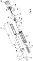
- the exemplary medicament delivery device shown in the drawings comprises a generally elongated housing having proximal and distal ends, a delivery member 40 connected to the housing; a medicament container 84 operably arranged within the housing; a drive mechanism capable of acting on the medicament container for priming and for expelling a dose of medicament; wherein the device further comprises an activator mechanism configured to interact with the drive mechanism, such that a first interaction between the activator mechanism and the drive mechanism causes the container to move towards the delivery member wherein the container is primed and such that a subsequent second interaction between the activator mechanism and the drive mechanism causes a dose of medicament to be expelled through the delivery member.
- the activator mechanism is configured such that the second interaction is prevented to be achieved until the first interaction is achieved as it will be explained below.
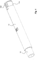
- the housing comprises a tubular first housing part 10, Fig. 1 , being open at both ends and a second housing part 114 attached to the distal end of the first housing part. These two housing parts may be considered as one component.
- the activator mechanism comprises a contactor 12 operably arranged to the housing at a proximal end thereof; a rotator 82 operably arranged inside the housing and operably connected to the contactor 12 and to the drive mechanism; and a safety member 128 operably arranged to the housing at a distal end thereof and operably connected to the rotator.
- the contactor is axially movable in relation to the housing between an extended position in which the delivery member is hidden and protected by the contactor and a retracted position in which the delivery member is exposed.
- the contactor and the rotator are arranged to interact with each other such that the rotator prevents the contactor from being moved from the extended position to the retracted position, until the first interaction is completed.
- the first interaction is an interaction between the rotator and the drive mechanism caused by an interaction between the safety member and the rotator, whereby removal of the safety member 128 causes a rotation of the rotator 82 such that the drive mechanism may act on the container for priming the container. This interaction will be explained below in detail.
- the contactor 12 is in the embodiment shown as a delivery member cover.
- the contactor 12 comprises a generally tubular proximal part 14 having a transversal proximal end wall 16, Fig. 2 .
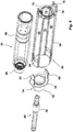
- Two longitudinally extending arms 18, Fig. 4 extend towards the distal end from the tubular part 14.
- Each of the extending arms 18 has an outer surface with a curvature that generally corresponds to the inner surface of the first housing part 10, whereby the contactor is slidable in the longitudinal direction in relation to the first housing part.
- the outer surfaces of the arms 18 are arranged with guide ribs 20, Fig. 4 , which guide ribs 20 are intended to fit into longitudinally extending grooves 22 on the inner surface of the first housing part 10, Fig.
- the contactor 12 is guided during longitudinal sliding of the contactor 12 in relation to the first housing part 10 and prevent a rotation of the contactor in relation to the housing.
- the contactor is arranged within the housing such that the tubular part 14 protrudes from the proximal end of the housing.
- the contactor 12 is further arranged with two generally radially flexing tongues 24, Fig. 4 , one on each arm and with the free ends facing the proximal end of the contactor 12.
- the tongues 24 are arranged such that they have a certain inclination somewhat inwards in their free un-tensioned state.
- the transversal end wall 16 of the contactor is further provided with a centrally positioned passage 26, Fig. 2 , through which a delivery member, such as an injection needle, may pass when the device is used, as will be described.
- the contactor comprises a number of third contact members 30.
- Each of the arms 18 of the contactor 12 is arranged with a third contact member 30 which may be a protrusion, Fig. 4 , on inner surfaces thereof at a distal end area of the arms.
- the delivery member 40 is an injection needle assembly comprising a hub 38 wherein an injection needle is arranged with a proximal pointed end 42 and a distal pointed end 44 and wherein the distal pointed end 44 and the proximal pointed end 42 are surrounded and covered with respective protective sheaths 48, 46, Fig. 5 .
- the hub 38 has further a proximally directed ledge and a distally directed ledge and the sheaths 46, 48 are of a suitable flexible material such as rubber or silicone and press-fit on the ledges of the hub 38, for protecting the needle and for keeping the needle sterile before use.
- the injection needle assembly is fixedly connected to the housing.
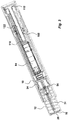
- a contactor force member 31 which may be a compression spiral spring, is pre-tensioned arranged with a proximal end in contact with a distally directed surface of the transversal end wall 16 for urging the contactor 12 in the proximal direction.
- the distal end of the contactor force member 31 is in contact with a delivery member holder 32, Fig. 5 , arranged in the first housing part 10.
- the delivery member holder 32 has a first section 34 with a generally tubular shape with distal and proximal openings. The proximal opening is arranged with a circumferential ledge 36. Inside the first section 34, the hub 38 may be positioned. The hub 38 is shaped to fit into the first section 34, preferably with some friction.
- the delivery member holder 32 is fixedly attached to the first housing part. Alternatively the first housing and the delivery member holder 32 are integral.
- a second section 50 of the delivery member holder 32 is also generally tubular and designed such that the distal pointed end 44 of the injection needle 40 protrudes into the interior of the second section 50.
- the diameter of the second section 50 is chosen such that a neck portion 52 of a proximal section 54 of a medicament container holder 56, Fig. 6 , may fit therein.
- the proximal section 54 of the medicament container holder comprises a circular end wall 58 with two distally extending tongues 60, where the tongues 60 are arranged to be flexible in the radial direction.
- the free ends of the tongues are arranged with radially outwardly extending ledges 62, which ledges 62 have a wedge-shape as seen in Fig. 7 .
- the ledges 62 of the tongues 60 are designed to fit into recesses 64, Fig. 6 , arranged in a proximal area of an elongated second section 66 of the medicament container holder 56 such as to connect the two sections with each other.
- the second section 66 is arranged with two diametrically positioned first wall sections 68 extending from the neck portion and having dimensions and curvature generally corresponding to the inner surface of the first housing part 10.
- the first wall sections 68 are attached to diametrically positioned second wall sections 70 having dimension such that the arms 18 of the contactor 12 can be accommodated.
- the distal ends of the first and second wall sections are attached to an end wall 72, which end wall 72 is arranged with a central passage 74.
- the end wall 72 is arranged with generally inwardly directed protrusions 76 positioned diametrically with respect to each other.
- the medicament container holder is designed to accommodate the medicament container 84, Fig. 6 , provided with a neck portion 86, which neck portion fits into the neck portion 52 of the medicament container holder 56, and is sealed off by a flexible membrane, a septum. The distal end of the medicament container is sealed off by a movable stopper 88.
- each loop comprises a radial inwardly extending protrusion or ledge.
- Each of the radial inwardly extending protrusion or ledge is arranged such that it may be inter-connected with radial outwardly extending protrusions 80 on an outer surface of the rotator 82, Fig. 7 , such that the medicament container holder 56 is held in an initial position in which the medicament container holder 56 with its container is placed such that there is a distance between the distal pointed end 44 of the injection needle 40 and the neck portion of the medicament container, Fig. 3 .
- the contactor 12 In order for the contactor 12 not to be pushed out from the housing in the proximal direction by the contactor force member 31, it is held in position by the tongues 24 of the arms of the contactor being in contact with a distal annular surface of the delivery member holder 32, as seen in Fig. 3 .
- the second interaction is a further interaction between the contactor and the rotator causing a further interaction between the rotator and the drive mechanism, whereby movement of the contactor from the extended to the retracted position causes a further rotation of the rotator 82 such that the drive mechanism may further act on the container for expelling a dose of medicament through the delivery member.
- This second interaction will be explained below in detail.
- the rotator 82 is a sleeve-shaped member having an outer and an inner surface.
- the outer surface of the rotator 82 is arranged with a number of outer guiding members of different functions.
- the outer surface of the rotator 82 is arranged with first outer guiding members 94, Fig. 7 , which are transversal circumferential ledges located at a distal end of the rotator 82, and are arranged with cut-outs 96 at two diametrical positions, which cut-outs 96 have a certain width.
- the functions of the first outer guiding members 94 and cut-outs 96 will be explained below.
- the rotator is operably connected to the housing.
- the rotator is rotatably and slidably locked to the housing, more preferably to the second housing part.
- the rotator further comprises on it outer surface holding members 93 which are preferably radial outwardly protrusions or ledges configured to interact with corresponding holding members which are preferably radial inwardly protrusions or ledges 115 on the inner surface of the second housing part such that the rotator may rotate in relation to said housing but is prevented to be longitudinally movable.
- Each second outer guiding member 90 comprises a first outer longitudinal section 90 I , a first outer transversal and circumferential section 90 II , a second outer longitudinal section 90 III , an outer inclined section 90 IV , a third outer longitudinal section 90 V , and a fourth outer longitudinal section 90 VI which is parallel with the first, second and third outer longitudinal sections.
- the first outer longitudinal section 90 I is connected to the first outer transversal and circumferential section 90 II .
- This section is then connected to the second outer longitudinal section 90 III , which in turn emerges into the outer inclined section 90 IV continuing in the third outer longitudinal section 90 V .
- the fourth outer longitudinal section 90 VI is parallel with the first, second and third outer longitudinal sections.
- first lock member 92 Adjacent this fourth outer longitudinal section is a first lock member 92 which is a generally radially flexing tongue having a free end pointing in the proximal direction.
- the shape of the tongue 92 as seen in a side view of Fig. 7 is generally a wedge.
- the inner surface of the rotator 82 is arranged with a number of inner guiding members 100 which may be two sets of ledge sections, Fig. 8 .
- Each inner guiding member 100 comprises a first inner longitudinal section 100 I , a first inner transversal and circumferential section 100 II , an inner inclined section 100 III , second inner longitudinal section 100 IV , a second inner transversal and circumferential section 100 V , third inner longitudinal section 100 VI , and a third inner transversal and circumferential section 100 VII .
- the first inner longitudinal section 100 I is connected to the first inner transversal and circumferential section 100 II .
- This section is in turn connected to the inner inclined section 100 III which is inclined with respect to the longitudinal direction.
- the inner inclined section 100 III is connected to the second inner longitudinal section 100 IV , which in turn is connected to the second inner transversal and circumferential section 100 V .
- This section is in turn connected to the third inner longitudinal section 100 VI , which terminates with the third inner transversal and circumferential section 100 VII .
- a long inner longitudinal section 100 VIII extending in the proximal direction is connected to the third inner transversal and circumferential section 100 VII .
- the two ledge sections are placed diametrically opposed on the inner surface of the rotator.
- the plunger rod 102 is initially positioned such that a proximal end thereof is in contact with the stopper 88 of the medicament container 84.
- the plunger rod 102 comprises a number of first contact members 104 which may be two generally radially outwardly extending protrusions. These first contact members 104 are intended to interact with the inner guiding members 100 on the inner surface of the rotator 82.
- the plunger rod 102 is further arranged with two longitudinally extending grooves 106.
- the plunger rod is a hollow rod and inside the plunger rod 102 a force member 108 is positioned, also comprised in the drive mechanism, Figs. 2 and 3 .
- the force member 108 is in the embodiment shown as a compression spiral spring having a proximal end in contact with an end wall 110 at the proximal end of the plunger rod. A distal end of the force member 108 is in contact with a wall section 112 of the second housing part 114, Fig. 4 .
- the force member 108 is pre-tensioned and has a predetermined load force configured to act on the plunger rod.
- the first contact members 104 of the plunger rod 102 are configured to interact with the inner guiding members 100 of the rotator 82 for holding the plunger rod in an initial state, an intermediate state and in a final state depending on the rotational position of the rotator 82.
- the second housing part 114 is intended to be connected to the distal end of the first housing part and is arranged with two proximally directed arms 116, where each arm is arranged with a generally radially flexible tongue 118, having a free end in the distal direction.
- the tongues 118 are arranged with outwardly directed ledges, which ledges are intended to fit into cut-outs 120 on a distal area of the first housing part 10, for locking the two housing parts together.
- the end wall 112 of the second housing part 114 is arranged with a proximally directed spring guide rod 122, intended to guide and support the force member 108.
- the end wall 112 of the second housing part 114 is further arranged with a number of passages 124, in the embodiment shown two passages arranged diametrically.
- the outer surface of the second housing part is further arranged with two diametrically opposed recesses 126.
- the safety member 128 is releasibly attached to the second housing part. It comprises an end wall 130. On the end wall 130, two proximally directed grip panels 132 are arranged, which grip panels 132 are intended to fit into the recesses 126 of the second housing part 114.
- the safety member 128 further comprises second contact members 134, which are two arms attached to the end wall 130, also being directed in the proximal direction. These second contact members 134 are intended to fit into the passages 124 of the second housing part 114 and in the cut-outs 96 of first outer guiding members 94 of the rotator 82.
- the second contact members 134 are arranged with side edges 136 having a curved shape as seen in Fig. 4 , providing a side-directed protrusion. The function of the shape of the second contact members will be explained below.
- the device is intended to function as follows.
- the device When delivered to the user, the device is preferably assembled and ready to use.
- the delivery member 40 here an injection needle is fitted into the holder 32 of the first housing part 10 and a medicament container 84 has been placed in the medicament container holder 56.
- the medicament container holder 56 with its container is placed such that there is a distance between the distal pointed end 44 of the injection needle 40 and the neck portion of the medicament container, Fig. 3 .
- the safety member 128 is attached to the second housing part 114.
- the contactor 12 is in the extended position urged by the contactor force member 31.
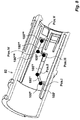
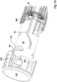
- the contactor 12 is locked from being moved from the extended to the retracted position in relation to the first housing part due to the interaction between the third contact members 30 of the contactor 12 and the first outer transversal and circumferential section 90 II of the second outer guiding members 90 on the outer surface of the rotator 82, as seen in Fig. 10 , wherein the first outer transversal and circumferential section 90 II will function as a blocking member.
- the plunger rod 102 is held in the initial state due to the interaction between each of the first contact members 104 of the plunger rod 102 and each of the first inner transversal and circumferential sections 100 II of the inner guiding members 100 on the inner surface of the rotator 82 as seen in Fig. 8 , pos. I. until the rotator 82 is turned when the safety member 128 is removed.
- the safety member 128 When the device is to be used, the safety member 128 is removed from the device by a user gripping the grip panels 132 and longitudinally pulling the safety member 128 in the distal direction. Thereby the second contact members 134 are also longitudinally moved in the distal direction and the curved side surfaces 136 which are in contact with an end surface of the first outer guiding members 94 as seen in Fig. 10 , forces the rotator 82 to rotate a certain rotational angle.
- the rotation of the rotator 82 when removing the safety member 128 causes the first contact members 104 of the plunger rod 102 to be released or to be moved from the initial state where they leave the contact with the first inner transversal and circumferential section 100 II of the inner guiding member 100 on the inner surface of the rotator 82 and come in contact with the inner inclined section 100 III as seen in Fig. 8 , pos. II.
- the plunger rod 102 is then forced to move proximally by the force member 108, and the contact with the inner inclined surface 100 III will cause the rotator 82 to rotate a further angle such that the radial inwardly extending protrusions or ledges of the loops 78 are released from the radial outwardly extending protrusions 80 on the outer surface of the rotator 82.
- the plunger rod 102 act with a force on the stopper 88 of the medicament container 84 such that the medicament container 84 and the medicament container holder 56 move as a unit in the proximal direction.
- this movement now causes the distal pointed end 44 of the injection needle 40 to first penetrate the protective sheath 48 and then a septum at the neck portion of the medicament container 84, while compressing the protective sheath 48 surrounding the distal end of the needle, Fig. 11 .
- the movement of the plunger rod 102 is stopped when the first contact members 104 hit the second inner transversal and circumferential section 100 V , Fig. 8 , pos. III.
- the plunger rod 102 has moved from the initial state to the intermediate state.
- the plunger rod 102 is held in the intermediate state due to the interaction between each of the first contact members 104 of the plunger rod 102 and each of the second inner transversal and circumferential sections 100 V of the inner guiding members 100 on the inner surface of the rotator 82.
- the rotation of the rotator 82 causes the first outer guiding members 94 to move to a position in front of the passages 124 of the second housing part. Any attempts to reintroduce the second contact members 134 of the safety member 128 into the passages 124 of the second housing part 114 are thereby prevented.
- the first outer guiding members 94 on the rotator prevent re-connection of the safety member 128 after removal of the safety member and turning of the rotator.
- the next step is then to perform a manual penetration or semi-penetration such that the contactor moves in relation to the delivery member to expose the proximal pointed end 42 of the injection needle.
- the transversal end wall 16 of the contactor is positioned on a delivery site i.e. an injection site and the contactor 12 is thereby pressed against the delivery site, whereby the contactor 12 will be moved, relative to the housing, in the distal direction from the extended position to the retracted position whereby the contactor force member 31 is compressed.
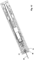
- the proximal end of the injection needle will then penetrate the proximal protective sheath 46 and pass through the passage 26 on the transversal end wall 16 of the contactor and into the tissue of a user, Fig. 12 .
- each of the third contact members 30 of the contactor 12 will first pass along each of the second outer longitudinal sections 90 III and then come in contact with each of the outer inclined sections 90 IV , Fig. 7 , pos. III.
- This further rotation allows the plunger rod to move from the intermediate state in which the plunger rod is held due to the interaction between each of the first contact members 104 of the plunger rod 102 and each of the second inner transversal and circumferential sections 100 V of the inner guiding members 100 on the inner surface of the rotator 82, to a final state in which the plunger rod is prevented from moving further due to the interaction between each of the first contact members 104 of the plunger rod 102 and each of third inner transversal and circumferential section 100 VII of the inner guiding members 100 on the inner surface of the rotator 82.
- This movement causes the stopper 88 of the medicament container 84 to be moved in the proximal direction, from pos. IV to pos. V, whereby a dose of medicament is expelled through the delivery member 40 at the delivery site.
- the delivery is stopped when the first contact members 104 of the plunger rod 102 are moved in contact with the third inner transversal and circumferential section 100 VII , Fig. 8 , pos. V.
- the device may then be removed from the delivery site whereby the contactor force member 31 will urge the contactor 12 in the proximal direction, relative to the housing, from the retracted position to the extended position.
- the third contact members 30 of the contactor will move axially along the rotator, Fig. 7 , until they pass the first lock members 92 of the rotator, pos. V, Fig. 7 .
- the lock members 92 will flex radially inwards as the third contact members pass from pos. IV to pos. V. Afterwards they will flex back and their wedge shape prevents the contactor 12 from being moved again in the distal direction from the extended to the retracted position.
- the delivery member 40 i.e. an injection needle, is hidden and protected inside the contactor, preventing any accidental needle sticks.
- the device may now be discarded.
Landscapes
- Health & Medical Sciences (AREA)
- Engineering & Computer Science (AREA)
- Hematology (AREA)
- Anesthesiology (AREA)
- Biomedical Technology (AREA)
- Heart & Thoracic Surgery (AREA)
- Vascular Medicine (AREA)
- Life Sciences & Earth Sciences (AREA)
- Animal Behavior & Ethology (AREA)
- General Health & Medical Sciences (AREA)
- Public Health (AREA)
- Veterinary Medicine (AREA)
- Infusion, Injection, And Reservoir Apparatuses (AREA)
- Environmental & Geological Engineering (AREA)
Claims (5)
- Medikamentenverabreichungsvorrichtung, umfassend:- ein Gehäuse (10, 114) mit einem proximalen Ende und einem distalen Ende,- ein Verabreichungselement, das mit dem Gehäuse verbunden ist, wobei das Verabreichungselement eine Injektionsnadel (40) mit einem proximalen spitzen Ende (42) und einem distalen spitzen Ende (44) einschließt;- einen Medikamentenbehälter (84), der betriebsfähig innerhalb des Gehäuses angeordnet ist;- einen Antriebsmechanismus (102, 108), der eine Kolbenstange (102) umfasst und zum Einwirken auf den Medikamentenbehälter (84) zum Bereitmachen und zum Abgeben einer Medikamentendosis fähig ist;dadurch gekennzeichnet, dass die Vorrichtung ferner umfasst:einen Betätigungselementmechanismus, der dazu konfiguriert ist, mit dem Antriebsmechanismus zu interagieren;wobei der Betätigungselementmechanismus ein Drehelement (82) einschließt, das betriebsfähig innerhalb des Gehäuses (10, 114) angeordnet ist; ein Sicherheitselement (128), das entfernbar an dem distalen Ende des Gehäuses angeordnet und betriebsfähig mit dem Drehelement (82) verbunden ist;wobei das Sicherheitselement (128) zweite Kontaktelemente (134) umfasst, die mit Seitenkanten (136) mit einer gekrümmten Form angeordnet sind;wobei ein Entfernen des Sicherheitselements (128) durch Ziehen in eine distale Richtung bewirkt, dass gekrümmte Seitenoberflächen (136), die mit einer Oberfläche am Ende eines ersten äußeren Führungselements (94) des Drehelements (82) in Kontakt stehen, eine Drehung des Drehelements (82) erzwingen, was bewirkt, dass sich erste Kontaktelemente (104) der Kolbenstange (102) aus einem Ausgangszustand bewegen, in dem sie einen Kontakt mit einem ersten inneren Quer- und Umfangsabschnitt (100II) eines inneren Führungselements (100) auf der Innenoberfläche des Drehelements (82) aufgeben und mit einem inneren geneigten Abschnitt (100III) des inneren Führungselements (100III) in Kontakt kommen, so dass der Antriebsmechanismus (102, 108) den Medikamentenbehälter (84) und einen Medikamentenbehälterhalter (56) als eine Einheit in der proximalen Richtung zu dem distalen spitzen Ende (44) der Injektionsnadel (40) bewegt, um zuerst die Schutzhülle (48) und dann ein Septum an dem Halsabschnitt des Medikamentenbehälters (84) zu durchdringen, während eine Schutzhülle (48), die das distale Ende der Nadel umgibt, zusammengedrückt wird.
- Medikamentenverabreichungsvorrichtung nach Anspruch 1, wobei der Antriebsmechanismus umfasst: eine Kolbenstange (102) und ein Kraftelement (108) mit einer vorbestimmten Belastungskraft, das dazu konfiguriert ist, auf die Kolbenstange einzuwirken.
- Medikamentenverabreichungsvorrichtung nach Anspruch 1, wobei jedes der inneren Führungselemente (100) ferner einen ersten inneren Längsabschnitt (100I), einen zweiten inneren Längsabschnitt (100IV), einen zweiten inneren Quer- und Umfangsabschnitt (100V), einen dritten inneren Längsabschnitt (100VI) und einen dritten inneren Quer- und Umfangsabschnitt (100VII) umfasst.
- Medikamentenverabreichungsvorrichtung nach Anspruch 1, wobei das Sicherheitselement (128) zweite Kontaktelemente (134) umfasst, die dazu angeordnet sind, mit ersten äußeren Führungselementen (94) an dem Drehelement (82) zusammenzuwirken, die nach dem Entfernen des Sicherheitselements (128) zum Drehen des Drehelements (82) um einen bestimmten Drehwinkel fähig sind, sodass die Kolbenstange aus dem Ausgangszustand in einen Zwischenzustand freigegeben wird, und den Medikamentenbehälter zu dem distalen spitzen Endes der Injektionsnadel (40) zu bewegen, um zuerst die Schutzhülle (48) und dann ein Septum an dem Halsabschnitt des Medikamentenbehälters (84) zu durchdringen, während die Schutzhülle 48, die das distale Ende der Nadel umgibt, zusammengedrückt wird.
- Medikamentenverabreichungsvorrichtung nach einem der vorstehenden Ansprüche, wobei das proximale spitze Ende (42) und das distale spitze Ende (44) von jeweiligen Schutzhüllen (48, 46) umgeben und bedeckt sind.
Applications Claiming Priority (4)
| Application Number | Priority Date | Filing Date | Title |
|---|---|---|---|
| US201261745053P | 2012-12-21 | 2012-12-21 | |
| SE1251499 | 2012-12-21 | ||
| EP13814065.2A EP2934628B1 (de) | 2012-12-21 | 2013-12-06 | Medikamentenabgabevorrichtung |
| PCT/EP2013/075789 WO2014095424A1 (en) | 2012-12-21 | 2013-12-06 | Medicament delivery device |
Related Parent Applications (2)
| Application Number | Title | Priority Date | Filing Date |
|---|---|---|---|
| EP13814065.2A Division EP2934628B1 (de) | 2012-12-21 | 2013-12-06 | Medikamentenabgabevorrichtung |
| EP13814065.2A Division-Into EP2934628B1 (de) | 2012-12-21 | 2013-12-06 | Medikamentenabgabevorrichtung |
Publications (2)
| Publication Number | Publication Date |
|---|---|
| EP3566733A1 EP3566733A1 (de) | 2019-11-13 |
| EP3566733B1 true EP3566733B1 (de) | 2021-06-02 |
Family
ID=50977623
Family Applications (2)
| Application Number | Title | Priority Date | Filing Date |
|---|---|---|---|
| EP19181670.1A Active EP3566733B1 (de) | 2012-12-21 | 2013-12-06 | Medikamentenverabreichungsvorrichtung |
| EP13814065.2A Active EP2934628B1 (de) | 2012-12-21 | 2013-12-06 | Medikamentenabgabevorrichtung |
Family Applications After (1)
| Application Number | Title | Priority Date | Filing Date |
|---|---|---|---|
| EP13814065.2A Active EP2934628B1 (de) | 2012-12-21 | 2013-12-06 | Medikamentenabgabevorrichtung |
Country Status (12)
| Country | Link |
|---|---|
| US (5) | US9987436B2 (de) |
| EP (2) | EP3566733B1 (de) |
| JP (1) | JP6139697B2 (de) |
| KR (1) | KR101745226B1 (de) |
| CN (1) | CN104968381B (de) |
| AU (1) | AU2013361831B2 (de) |
| BR (1) | BR112015014658A2 (de) |
| CA (1) | CA2895586C (de) |
| IL (1) | IL239527A0 (de) |
| RU (1) | RU2621413C2 (de) |
| TW (1) | TWI569835B (de) |
| WO (1) | WO2014095424A1 (de) |
Families Citing this family (76)
| Publication number | Priority date | Publication date | Assignee | Title |
|---|---|---|---|---|
| EP2399635A1 (de) | 2010-06-28 | 2011-12-28 | Sanofi-Aventis Deutschland GmbH | Automatischer Injektor |
| EP3566733B1 (de) * | 2012-12-21 | 2021-06-02 | SHL Medical AG | Medikamentenverabreichungsvorrichtung |
| US10799630B2 (en) | 2014-12-19 | 2020-10-13 | Amgen Inc. | Drug delivery device with proximity sensor |
| US10585107B2 (en) * | 2015-02-06 | 2020-03-10 | Bd Kiestra B.V. | Dish rotation directly driven from transport belt |
| EP3064239A1 (de) * | 2015-03-05 | 2016-09-07 | Carebay Europe Ltd. | Wirkstoffverabreichungsvorrichtung mit Informationsbereitstellungssystem |
| US10363373B2 (en) | 2015-04-24 | 2019-07-30 | Shl Medical Ag | Medicament delivery device |
| US20200384209A1 (en) * | 2015-04-24 | 2020-12-10 | Shl Medical Ag | Drive mechanism |
| WO2016169719A1 (en) * | 2015-04-24 | 2016-10-27 | Carebay Europe Ltd | Drive mechanism |
| DK3310413T3 (en) * | 2015-06-19 | 2019-04-23 | Shl Medical Ag | Drug delivery device |
| CN108025144B (zh) | 2015-07-23 | 2020-12-01 | 艾斯曲尔医疗公司 | 可变单次剂量注射器 |
| WO2017029032A1 (en) * | 2015-08-19 | 2017-02-23 | Carebay Europe Ltd | Variable single dose medicament delivery device |
| WO2017060017A1 (en) * | 2015-10-05 | 2017-04-13 | Carebay Europe Ltd | Medicament delivery training device |
| USD819200S1 (en) | 2015-11-06 | 2018-05-29 | Amgen Inc. | Autoinjector with removable cap |
| JP7026614B2 (ja) * | 2015-11-27 | 2022-02-28 | サノフィ-アベンティス・ドイチュラント・ゲゼルシャフト・ミット・ベシュレンクテル・ハフツング | 薬剤注射デバイス |
| USD822198S1 (en) | 2015-12-09 | 2018-07-03 | Amgen Inc. | Autoinjector with removable autoinjector cap |
| GB2545266B (en) | 2015-12-11 | 2018-08-08 | Oval Medical Tech Limited | Autoinjector with retracting needle |
| EP3184134A1 (de) | 2015-12-21 | 2017-06-28 | Carebay Europe Ltd. | Rohrförmiger rotator für eine medikamentenabgabevorrichtung und medikamentenausgabevorrichtung mit selbigem |
| USD814022S1 (en) * | 2016-04-20 | 2018-03-27 | Amgen Inc. | Autoinjector with removable cap |
| USD819198S1 (en) | 2016-04-28 | 2018-05-29 | Amgen Inc. | Autoinjector with removable cap |
| USD830539S1 (en) | 2016-05-02 | 2018-10-09 | Amgen Inc. | Autoinjector |
| EP3458128B1 (de) * | 2016-05-18 | 2020-07-01 | SHL Medical AG | Verarbreichungsmechanismus für eine medikamentenabgabesystem |
| US10328205B2 (en) * | 2016-07-07 | 2019-06-25 | Shl Medical Ag | Drug delivery device with pneumatic power pack |
| US10967128B2 (en) | 2016-07-14 | 2021-04-06 | Shl Medical Ag | Administration mechanism for a medicament delivery device |
| CN109475693B (zh) * | 2016-07-19 | 2022-07-22 | 赛诺菲 | 药剂注射器装置 |
| EP3315153A1 (de) * | 2016-10-25 | 2018-05-02 | Sanofi-Aventis Deutschland GmbH | Medikamenteninjektionsvorrichtung |
| KR102110292B1 (ko) * | 2017-01-20 | 2020-05-14 | 엘.쥐.피. 테크노로지 홀딩스 엘엘씨 | 자동 주사기 장치 |
| USD827128S1 (en) | 2017-03-14 | 2018-08-28 | Amgen Inc. | Handheld drug delivery device |
| CN110545863B (zh) * | 2017-04-25 | 2021-06-01 | 群康生技股份有限公司 | 注射笔 |
| USD834182S1 (en) * | 2017-06-20 | 2018-11-20 | Genesis Cosmetics LLC | Syringe |
| JP1629611S (de) * | 2017-10-25 | 2019-04-15 | ||
| WO2019086371A1 (en) * | 2017-10-30 | 2019-05-09 | Sanofi | Injector device |
| EP3492124A1 (de) | 2017-12-01 | 2019-06-05 | Sanofi | Injektorvorrichtung |
| CN109984815B (zh) * | 2017-12-31 | 2022-05-10 | 江苏风和医疗器材股份有限公司 | 一种无芯穿刺器 |
| JP7184910B2 (ja) * | 2018-02-16 | 2022-12-06 | ベクトン ディキンソン フランス | 医薬品組成物で充填された医療用容器を支持するための医療用注射デバイス |
| CN112218670A (zh) * | 2018-04-11 | 2021-01-12 | 赛诺菲 | 药物递送装置 |
| USD926967S1 (en) * | 2018-05-22 | 2021-08-03 | Sanofi | Injection device |
| EP4603124A3 (de) | 2018-06-08 | 2025-11-12 | Antares Pharma, Inc. | Injektor mit automatischer insertion |
| CA3204309C (en) | 2018-07-24 | 2026-04-28 | Antares Pharma, Inc. | Formulations for naloxone hyrdochloride injection |
| USD926975S1 (en) * | 2018-09-27 | 2021-08-03 | Phc Holdings Corporation | Cartridge for medicine injector |
| GB2577549B (en) * | 2018-09-28 | 2021-08-04 | Owen Mumford Ltd | Injection device with commit feature |
| KR102541325B1 (ko) * | 2018-12-20 | 2023-06-13 | 에스에이치엘 메디컬 아게 | 약물 전달 장치 |
| KR102607293B1 (ko) | 2019-02-26 | 2023-11-29 | 벡톤 디킨슨 프랑스 | 자동 주사 장치용 강성 바늘 쉴드 분리기 |
| CN113474028B (zh) | 2019-02-26 | 2023-07-14 | 贝克顿迪金森法国公司 | 带有针盖的自动注射器 |
| CN116421826B (zh) | 2019-02-26 | 2026-06-16 | 贝克顿迪金森法国公司 | 药物递送装置 |
| MX2021010055A (es) | 2019-02-26 | 2021-09-21 | Becton Dickinson France | Autoinyector con indicador de audio. |
| WO2020210513A1 (en) * | 2019-04-09 | 2020-10-15 | Battelle Memorial Institute | Autoinjectors having advanced release and sound features |
| USD1010811S1 (en) | 2019-09-30 | 2024-01-09 | Amgen Inc. | Handheld drug delivery device |
| PT4037735T (pt) | 2019-09-30 | 2025-10-27 | Amgen Inc | Dispositivo de entrega de fármacos |
| AU2020357708B2 (en) * | 2019-09-30 | 2025-06-26 | Amgen Inc. | Drug delivery device and methods of delivering a drug |
| EP4058102B1 (de) * | 2019-11-11 | 2025-10-01 | SHL Medical AG | Medikamentenverabreichungsvorrichtung |
| WO2021115706A1 (en) * | 2019-12-09 | 2021-06-17 | Shl Medical Ag | Assembly, cassette and medicament delivery device |
| USD1030040S1 (en) | 2020-01-14 | 2024-06-04 | Amgen Inc. | Handheld drug delivery device |
| USD1030041S1 (en) | 2020-01-14 | 2024-06-04 | Amgen Inc. | Handheld drug delivery device |
| EP4093464B1 (de) * | 2020-01-24 | 2025-07-23 | SHL Medical AG | Behälterhalteranordnung für medikamentenverabreichungsvorrichtung sowie medikamentenabgabevorrichtung |
| USD956211S1 (en) | 2020-02-28 | 2022-06-28 | Amgen Inc. | Handheld drug delivery device |
| EP4232125B1 (de) * | 2020-10-21 | 2026-02-18 | SHL Medical AG | Anordnung für eine medikamentenabgabevorrichtung |
| CN116419770A (zh) * | 2020-10-21 | 2023-07-11 | 康迈德有限公司 | 药物递送系统 |
| USD974547S1 (en) | 2020-11-05 | 2023-01-03 | Amgen Inc. | Handheld drug delivery device |
| JP2021500643S (ja) | 2020-11-05 | 2022-12-27 | 注射器 | |
| USD973866S1 (en) | 2020-11-05 | 2022-12-27 | Amgen Inc. | Handheld drug delivery device |
| USD985118S1 (en) | 2021-03-10 | 2023-05-02 | Amgen Inc. | Handheld drug delivery device |
| USD985116S1 (en) | 2021-03-10 | 2023-05-02 | Amgen Inc. | Handheld drug delivery device |
| USD985117S1 (en) | 2021-03-10 | 2023-05-02 | Amgen Inc. | Handheld drug delivery device |
| USD985119S1 (en) | 2021-03-30 | 2023-05-02 | Amgen Inc. | Handheld drug delivery device |
| WO2023006907A1 (en) | 2021-07-28 | 2023-02-02 | Shl Medical Ag | Apparatus for administration of medicine including monitoring and user feedback |
| US20250001067A1 (en) | 2021-07-28 | 2025-01-02 | Shl Medical Ag | Apparatus for large volume medication administration |
| JP7866045B2 (ja) * | 2021-10-14 | 2026-05-26 | エスエイチエル・メディカル・アーゲー | 薬剤送達デバイスカセットユニットのサブアッセンブリ、および、サブアッセンブリを含む薬剤送達デバイスカセットユニットを動作させる方法 |
| US20240416036A1 (en) * | 2021-10-22 | 2024-12-19 | Shl Medical Ag | Disposable cassette front module |
| EP4475912A1 (de) * | 2022-02-09 | 2024-12-18 | SHL Medical AG | Rotator für eine medikamentenabgabevorrichtung |
| US20260151571A1 (en) * | 2022-11-04 | 2026-06-04 | Shl Medical Ag | Medicament delivery device |
| WO2024170326A1 (en) * | 2023-02-13 | 2024-08-22 | Shl Medical Ag | A subassembly of a medicament delivery device |
| KR102694740B1 (ko) * | 2023-03-29 | 2024-08-14 | 주식회사 비에스엘 | 자동 약물 주입 장치 |
| WO2025233134A1 (en) * | 2024-05-10 | 2025-11-13 | Shl Medical Ag | A sub-assembly of a medicament delivery device |
| WO2026088018A1 (en) * | 2024-10-21 | 2026-04-30 | Phillips-Medisize Llc | Auto injector using a cartridge and sterile needle, and cassette system with cartridge |
| WO2026087211A1 (en) * | 2024-10-24 | 2026-04-30 | Shl Medical Ag | A sub-assembly of a medicament delivery device |
| WO2026112328A1 (en) * | 2024-11-22 | 2026-05-28 | Sanofi Pasteur Inc. | An intranasal medicament delivery system |
Family Cites Families (29)
| Publication number | Priority date | Publication date | Assignee | Title |
|---|---|---|---|---|
| RU2003351C1 (ru) * | 1991-06-26 | 1993-11-30 | Липов Борис Петрович; Сафронов Игорь Николаевич | Инъектор |
| US5540664A (en) * | 1993-05-27 | 1996-07-30 | Washington Biotech Corporation | Reloadable automatic or manual emergency injection system |
| US5658259A (en) * | 1995-10-19 | 1997-08-19 | Meridian Medical Technologies, Inc. | Dental cartridge assembly auto-injector with protective needle cover |
| CZ302178B6 (cs) * | 1999-07-27 | 2010-12-01 | Pharma Consult Ges. M. B. H. | Zarízení k automatickému injekcnímu vstrikování tekutin |
| US6387078B1 (en) * | 2000-12-21 | 2002-05-14 | Gillespie, Iii Richard D. | Automatic mixing and injecting apparatus |
| US7449012B2 (en) | 2004-08-06 | 2008-11-11 | Meridian Medical Technologies, Inc. | Automatic injector |
| EP1814616A1 (de) * | 2004-11-04 | 2007-08-08 | Sid Technologies Llc | Automatisches injektionsgerät |
| EP3002019B1 (de) * | 2004-11-24 | 2021-06-09 | SHL Medical AG | Injektionsvorrichtung |
| US20110226646A1 (en) * | 2004-12-06 | 2011-09-22 | Wyrick Ronald E | Kits Containing Medicine Injection Devices And Containers |
| NZ554828A (en) * | 2004-12-06 | 2010-07-30 | Washington Biotech Corp | Medicine injection devices and methods |
| WO2007131013A1 (en) | 2006-05-03 | 2007-11-15 | Antares Pharma, Inc. | Two-stage reconstituting injector |
| EP2121083A2 (de) * | 2007-02-01 | 2009-11-25 | PA Knowledge Limited | Automatisches injektionsgerät und adapter zur abdeckung der nadel des automatischen injektionsgeräts |
| GB0705388D0 (en) * | 2007-03-21 | 2007-04-25 | Medical House Plc The | Improved autoinjector |
| EP2237817B1 (de) * | 2007-11-14 | 2019-02-13 | SHL Group AB | Automatisches injektionsgerät mit aktiv ausgelöstem spritzenrückzug |
| GB2461087B (en) * | 2008-06-19 | 2012-09-26 | Cilag Gmbh Int | Injection device |
| EP2362795B1 (de) * | 2008-09-29 | 2018-04-25 | Becton Dickinson France | Automatische injektionsvorrichtung |
| US8579865B2 (en) * | 2009-03-20 | 2013-11-12 | Antares Pharma, Inc. | Hazardous agent injection system |
| AU2011224884B2 (en) * | 2010-03-09 | 2013-08-15 | Shl Medical Ag | Medicament delivery device |
| IT1398501B1 (it) * | 2010-03-10 | 2013-03-01 | Menarini Int Operations Lu Sa | Dispositivo autoiniettore di due dosi di farmaco |
| WO2011126439A1 (en) * | 2010-04-07 | 2011-10-13 | Shl Group Ab | Medicament delivery device |
| CA2804156A1 (en) * | 2010-07-02 | 2012-01-05 | Itero Biopharmaceuticals, Inc. | Preservative-free follicle stimulating hormone solution delivery device |
| CN103118723B (zh) * | 2010-08-19 | 2017-03-22 | 诺沃—诺迪斯克有限公司 | 具有针罩、衰减机构和可听和触觉反馈的用于手动针插入的医疗自动注射装置 |
| US9233209B2 (en) * | 2010-08-27 | 2016-01-12 | Novo Nordisk A/S | Medical injection device |
| TWI464003B (zh) * | 2010-11-18 | 2014-12-11 | 瑞健集團股份有限公司 | 藥物輸送裝置 |
| GB201020475D0 (en) * | 2010-12-02 | 2011-01-19 | Oval Medical Technologies Ltd | Delivery mechanism for an autoinjector |
| JP5767341B2 (ja) * | 2011-01-11 | 2015-08-19 | エス・ホー・エル・グループ・アクチボラゲットShl Group Ab | 薬剤送達装置 |
| EP2489387A1 (de) * | 2011-02-18 | 2012-08-22 | Sanofi-Aventis Deutschland GmbH | Automatischer Injektor |
| KR101664632B1 (ko) * | 2011-09-27 | 2016-10-24 | 에스에이치엘 그룹 에이비 | 최초 로크된 상태, 중간 프라이밍 상태, 및 약물 주입 상태를 갖는 약물 주입 장치 |
| EP3566733B1 (de) * | 2012-12-21 | 2021-06-02 | SHL Medical AG | Medikamentenverabreichungsvorrichtung |
-
2013
- 2013-12-06 EP EP19181670.1A patent/EP3566733B1/de active Active
- 2013-12-06 CA CA2895586A patent/CA2895586C/en active Active
- 2013-12-06 WO PCT/EP2013/075789 patent/WO2014095424A1/en not_active Ceased
- 2013-12-06 US US14/654,520 patent/US9987436B2/en active Active
- 2013-12-06 EP EP13814065.2A patent/EP2934628B1/de active Active
- 2013-12-06 BR BR112015014658A patent/BR112015014658A2/pt not_active IP Right Cessation
- 2013-12-06 JP JP2015548351A patent/JP6139697B2/ja not_active Expired - Fee Related
- 2013-12-06 RU RU2015129522A patent/RU2621413C2/ru active
- 2013-12-06 KR KR1020157019756A patent/KR101745226B1/ko not_active Expired - Fee Related
- 2013-12-06 AU AU2013361831A patent/AU2013361831B2/en not_active Ceased
- 2013-12-06 CN CN201380072316.5A patent/CN104968381B/zh not_active Expired - Fee Related
- 2013-12-17 TW TW102146674A patent/TWI569835B/zh not_active IP Right Cessation
-
2015
- 2015-06-18 IL IL239527A patent/IL239527A0/en unknown
-
2018
- 2018-05-31 US US15/994,398 patent/US10874804B2/en active Active
-
2020
- 2020-11-17 US US16/950,638 patent/US11779710B2/en active Active
-
2023
- 2023-07-10 US US18/220,128 patent/US12527920B2/en active Active
-
2025
- 2025-12-16 US US19/421,356 patent/US20260216446A1/en active Pending
Also Published As
| Publication number | Publication date |
|---|---|
| JP2016500321A (ja) | 2016-01-12 |
| IL239527A0 (en) | 2015-08-31 |
| BR112015014658A2 (pt) | 2017-07-11 |
| US9987436B2 (en) | 2018-06-05 |
| JP6139697B2 (ja) | 2017-05-31 |
| EP2934628B1 (de) | 2019-09-25 |
| EP3566733A1 (de) | 2019-11-13 |
| CA2895586C (en) | 2018-01-09 |
| RU2621413C2 (ru) | 2017-06-05 |
| US12527920B2 (en) | 2026-01-20 |
| CN104968381A (zh) | 2015-10-07 |
| RU2015129522A (ru) | 2017-01-27 |
| TWI569835B (zh) | 2017-02-11 |
| WO2014095424A1 (en) | 2014-06-26 |
| US20150335829A1 (en) | 2015-11-26 |
| CA2895586A1 (en) | 2014-06-26 |
| TW201433326A (zh) | 2014-09-01 |
| US20180272073A1 (en) | 2018-09-27 |
| KR101745226B1 (ko) | 2017-06-20 |
| AU2013361831B2 (en) | 2016-08-11 |
| US20210069428A1 (en) | 2021-03-11 |
| US11779710B2 (en) | 2023-10-10 |
| KR20150097784A (ko) | 2015-08-26 |
| AU2013361831A1 (en) | 2015-07-09 |
| US20230347070A1 (en) | 2023-11-02 |
| EP2934628A1 (de) | 2015-10-28 |
| CN104968381B (zh) | 2017-07-04 |
| US10874804B2 (en) | 2020-12-29 |
| US20260216446A1 (en) | 2026-07-30 |
Similar Documents
| Publication | Publication Date | Title |
|---|---|---|
| US12527920B2 (en) | Medicament delivery device | |
| EP1932558B1 (de) | Autoinjektor | |
| CN102939123B (zh) | 药物输送装置 | |
| EP3104909B1 (de) | Automatische injektionsvorrichtung | |
| EP2750739B1 (de) | Medizinische abgabevorrichtung mit einem anfänglichen verriegelungsstatus, zwischenfüllstatus und medikamentenabgabestatus | |
| EP2665503B1 (de) | Vorrichtung zur medikamentenverabreichung | |
| CN105025954B (zh) | 自动注射装置 | |
| EP2326367B1 (de) | Arzneiabgabevorrichtung mit mischmechanismus | |
| TWI576128B (zh) | 藥物輸送裝置 | |
| EP2978471B1 (de) | Medikamentenabgabevorrichtung mit einem verriegelungsmechanismus | |
| EP3481464B1 (de) | Medikamentenabgabevorrichtung mit pneumatischer einheit | |
| CN107438442B (zh) | 药物输送装置 | |
| EP4360679A1 (de) | Spritzenanordnung zur verwendung bei der arzneimittelabgabe | |
| EP4389175A1 (de) | Sicherheitsanordnung zur montage an einer spritze | |
| WO2024227740A1 (en) | Medicament delivery device |
Legal Events
| Date | Code | Title | Description |
|---|---|---|---|
| PUAI | Public reference made under article 153(3) epc to a published international application that has entered the european phase |
Free format text: ORIGINAL CODE: 0009012 |
|
| STAA | Information on the status of an ep patent application or granted ep patent |
Free format text: STATUS: THE APPLICATION HAS BEEN PUBLISHED |
|
| AC | Divisional application: reference to earlier application |
Ref document number: 2934628 Country of ref document: EP Kind code of ref document: P |
|
| AK | Designated contracting states |
Kind code of ref document: A1 Designated state(s): AL AT BE BG CH CY CZ DE DK EE ES FI FR GB GR HR HU IE IS IT LI LT LU LV MC MK MT NL NO PL PT RO RS SE SI SK SM TR |
|
| STAA | Information on the status of an ep patent application or granted ep patent |
Free format text: STATUS: REQUEST FOR EXAMINATION WAS MADE |
|
| 17P | Request for examination filed |
Effective date: 20200505 |
|
| RBV | Designated contracting states (corrected) |
Designated state(s): AL AT BE BG CH CY CZ DE DK EE ES FI FR GB GR HR HU IE IS IT LI LT LU LV MC MK MT NL NO PL PT RO RS SE SI SK SM TR |
|
| GRAP | Despatch of communication of intention to grant a patent |
Free format text: ORIGINAL CODE: EPIDOSNIGR1 |
|
| STAA | Information on the status of an ep patent application or granted ep patent |
Free format text: STATUS: GRANT OF PATENT IS INTENDED |
|
| RIC1 | Information provided on ipc code assigned before grant |
Ipc: A61M 5/31 20060101ALI20210215BHEP Ipc: A61M 5/20 20060101AFI20210215BHEP Ipc: A61M 5/24 20060101ALN20210215BHEP Ipc: A61M 5/32 20060101ALN20210215BHEP |
|
| RIC1 | Information provided on ipc code assigned before grant |
Ipc: A61M 5/20 20060101AFI20210308BHEP Ipc: A61M 5/31 20060101ALI20210308BHEP Ipc: A61M 5/24 20060101ALN20210308BHEP Ipc: A61M 5/32 20060101ALN20210308BHEP |
|
| INTG | Intention to grant announced |
Effective date: 20210323 |
|
| RIN1 | Information on inventor provided before grant (corrected) |
Inventor name: GIAMBATTISTA, LUCIO Inventor name: BENDEK, ANTONIO Inventor name: DANIEL, MATTIAS Inventor name: KARLSSON, SEBASTIAN |
|
| GRAS | Grant fee paid |
Free format text: ORIGINAL CODE: EPIDOSNIGR3 |
|
| GRAA | (expected) grant |
Free format text: ORIGINAL CODE: 0009210 |
|
| STAA | Information on the status of an ep patent application or granted ep patent |
Free format text: STATUS: THE PATENT HAS BEEN GRANTED |
|
| REG | Reference to a national code |
Ref country code: CH Ref legal event code: EP |
|
| AC | Divisional application: reference to earlier application |
Ref document number: 2934628 Country of ref document: EP Kind code of ref document: P |
|
| AK | Designated contracting states |
Kind code of ref document: B1 Designated state(s): AL AT BE BG CH CY CZ DE DK EE ES FI FR GB GR HR HU IE IS IT LI LT LU LV MC MK MT NL NO PL PT RO RS SE SI SK SM TR |
|
| REG | Reference to a national code |
Ref country code: GB Ref legal event code: FG4D |
|
| REG | Reference to a national code |
Ref country code: AT Ref legal event code: REF Ref document number: 1397849 Country of ref document: AT Kind code of ref document: T Effective date: 20210615 |
|
| REG | Reference to a national code |
Ref country code: IE Ref legal event code: FG4D |
|
| REG | Reference to a national code |
Ref country code: DE Ref legal event code: R096 Ref document number: 602013077830 Country of ref document: DE |
|
| REG | Reference to a national code |
Ref country code: LT Ref legal event code: MG9D |
|
| PG25 | Lapsed in a contracting state [announced via postgrant information from national office to epo] |
Ref country code: FI Free format text: LAPSE BECAUSE OF FAILURE TO SUBMIT A TRANSLATION OF THE DESCRIPTION OR TO PAY THE FEE WITHIN THE PRESCRIBED TIME-LIMIT Effective date: 20210602 Ref country code: HR Free format text: LAPSE BECAUSE OF FAILURE TO SUBMIT A TRANSLATION OF THE DESCRIPTION OR TO PAY THE FEE WITHIN THE PRESCRIBED TIME-LIMIT Effective date: 20210602 Ref country code: LT Free format text: LAPSE BECAUSE OF FAILURE TO SUBMIT A TRANSLATION OF THE DESCRIPTION OR TO PAY THE FEE WITHIN THE PRESCRIBED TIME-LIMIT Effective date: 20210602 Ref country code: BG Free format text: LAPSE BECAUSE OF FAILURE TO SUBMIT A TRANSLATION OF THE DESCRIPTION OR TO PAY THE FEE WITHIN THE PRESCRIBED TIME-LIMIT Effective date: 20210902 |
|
| REG | Reference to a national code |
Ref country code: NL Ref legal event code: MP Effective date: 20210602 |
|
| REG | Reference to a national code |
Ref country code: AT Ref legal event code: MK05 Ref document number: 1397849 Country of ref document: AT Kind code of ref document: T Effective date: 20210602 |
|
| PG25 | Lapsed in a contracting state [announced via postgrant information from national office to epo] |
Ref country code: GR Free format text: LAPSE BECAUSE OF FAILURE TO SUBMIT A TRANSLATION OF THE DESCRIPTION OR TO PAY THE FEE WITHIN THE PRESCRIBED TIME-LIMIT Effective date: 20210903 Ref country code: LV Free format text: LAPSE BECAUSE OF FAILURE TO SUBMIT A TRANSLATION OF THE DESCRIPTION OR TO PAY THE FEE WITHIN THE PRESCRIBED TIME-LIMIT Effective date: 20210602 Ref country code: PL Free format text: LAPSE BECAUSE OF FAILURE TO SUBMIT A TRANSLATION OF THE DESCRIPTION OR TO PAY THE FEE WITHIN THE PRESCRIBED TIME-LIMIT Effective date: 20210602 Ref country code: NO Free format text: LAPSE BECAUSE OF FAILURE TO SUBMIT A TRANSLATION OF THE DESCRIPTION OR TO PAY THE FEE WITHIN THE PRESCRIBED TIME-LIMIT Effective date: 20210902 Ref country code: SE Free format text: LAPSE BECAUSE OF FAILURE TO SUBMIT A TRANSLATION OF THE DESCRIPTION OR TO PAY THE FEE WITHIN THE PRESCRIBED TIME-LIMIT Effective date: 20210602 Ref country code: RS Free format text: LAPSE BECAUSE OF FAILURE TO SUBMIT A TRANSLATION OF THE DESCRIPTION OR TO PAY THE FEE WITHIN THE PRESCRIBED TIME-LIMIT Effective date: 20210602 |
|
| PG25 | Lapsed in a contracting state [announced via postgrant information from national office to epo] |
Ref country code: RO Free format text: LAPSE BECAUSE OF FAILURE TO SUBMIT A TRANSLATION OF THE DESCRIPTION OR TO PAY THE FEE WITHIN THE PRESCRIBED TIME-LIMIT Effective date: 20210602 Ref country code: PT Free format text: LAPSE BECAUSE OF FAILURE TO SUBMIT A TRANSLATION OF THE DESCRIPTION OR TO PAY THE FEE WITHIN THE PRESCRIBED TIME-LIMIT Effective date: 20211004 Ref country code: NL Free format text: LAPSE BECAUSE OF FAILURE TO SUBMIT A TRANSLATION OF THE DESCRIPTION OR TO PAY THE FEE WITHIN THE PRESCRIBED TIME-LIMIT Effective date: 20210602 Ref country code: SM Free format text: LAPSE BECAUSE OF FAILURE TO SUBMIT A TRANSLATION OF THE DESCRIPTION OR TO PAY THE FEE WITHIN THE PRESCRIBED TIME-LIMIT Effective date: 20210602 Ref country code: AT Free format text: LAPSE BECAUSE OF FAILURE TO SUBMIT A TRANSLATION OF THE DESCRIPTION OR TO PAY THE FEE WITHIN THE PRESCRIBED TIME-LIMIT Effective date: 20210602 Ref country code: CZ Free format text: LAPSE BECAUSE OF FAILURE TO SUBMIT A TRANSLATION OF THE DESCRIPTION OR TO PAY THE FEE WITHIN THE PRESCRIBED TIME-LIMIT Effective date: 20210602 Ref country code: SK Free format text: LAPSE BECAUSE OF FAILURE TO SUBMIT A TRANSLATION OF THE DESCRIPTION OR TO PAY THE FEE WITHIN THE PRESCRIBED TIME-LIMIT Effective date: 20210602 Ref country code: ES Free format text: LAPSE BECAUSE OF FAILURE TO SUBMIT A TRANSLATION OF THE DESCRIPTION OR TO PAY THE FEE WITHIN THE PRESCRIBED TIME-LIMIT Effective date: 20210602 Ref country code: EE Free format text: LAPSE BECAUSE OF FAILURE TO SUBMIT A TRANSLATION OF THE DESCRIPTION OR TO PAY THE FEE WITHIN THE PRESCRIBED TIME-LIMIT Effective date: 20210602 |
|
| PGFP | Annual fee paid to national office [announced via postgrant information from national office to epo] |
Ref country code: GB Payment date: 20211104 Year of fee payment: 9 Ref country code: FR Payment date: 20211125 Year of fee payment: 9 |
|
| PGFP | Annual fee paid to national office [announced via postgrant information from national office to epo] |
Ref country code: CH Payment date: 20211116 Year of fee payment: 9 |
|
| REG | Reference to a national code |
Ref country code: DE Ref legal event code: R097 Ref document number: 602013077830 Country of ref document: DE |
|
| PLBE | No opposition filed within time limit |
Free format text: ORIGINAL CODE: 0009261 |
|
| STAA | Information on the status of an ep patent application or granted ep patent |
Free format text: STATUS: NO OPPOSITION FILED WITHIN TIME LIMIT |
|
| PG25 | Lapsed in a contracting state [announced via postgrant information from national office to epo] |
Ref country code: DK Free format text: LAPSE BECAUSE OF FAILURE TO SUBMIT A TRANSLATION OF THE DESCRIPTION OR TO PAY THE FEE WITHIN THE PRESCRIBED TIME-LIMIT Effective date: 20210602 |
|
| 26N | No opposition filed |
Effective date: 20220303 |
|
| PG25 | Lapsed in a contracting state [announced via postgrant information from national office to epo] |
Ref country code: AL Free format text: LAPSE BECAUSE OF FAILURE TO SUBMIT A TRANSLATION OF THE DESCRIPTION OR TO PAY THE FEE WITHIN THE PRESCRIBED TIME-LIMIT Effective date: 20210602 |
|
| PG25 | Lapsed in a contracting state [announced via postgrant information from national office to epo] |
Ref country code: MC Free format text: LAPSE BECAUSE OF FAILURE TO SUBMIT A TRANSLATION OF THE DESCRIPTION OR TO PAY THE FEE WITHIN THE PRESCRIBED TIME-LIMIT Effective date: 20210602 Ref country code: IT Free format text: LAPSE BECAUSE OF FAILURE TO SUBMIT A TRANSLATION OF THE DESCRIPTION OR TO PAY THE FEE WITHIN THE PRESCRIBED TIME-LIMIT Effective date: 20210602 |
|
| REG | Reference to a national code |
Ref country code: BE Ref legal event code: MM Effective date: 20211231 |
|
| PG25 | Lapsed in a contracting state [announced via postgrant information from national office to epo] |
Ref country code: LU Free format text: LAPSE BECAUSE OF NON-PAYMENT OF DUE FEES Effective date: 20211206 Ref country code: IE Free format text: LAPSE BECAUSE OF NON-PAYMENT OF DUE FEES Effective date: 20211206 |
|
| PG25 | Lapsed in a contracting state [announced via postgrant information from national office to epo] |
Ref country code: BE Free format text: LAPSE BECAUSE OF NON-PAYMENT OF DUE FEES Effective date: 20211231 |
|
| P01 | Opt-out of the competence of the unified patent court (upc) registered |
Effective date: 20230425 |
|
| PG25 | Lapsed in a contracting state [announced via postgrant information from national office to epo] |
Ref country code: CY Free format text: LAPSE BECAUSE OF FAILURE TO SUBMIT A TRANSLATION OF THE DESCRIPTION OR TO PAY THE FEE WITHIN THE PRESCRIBED TIME-LIMIT Effective date: 20210602 |
|
| PG25 | Lapsed in a contracting state [announced via postgrant information from national office to epo] |
Ref country code: HU Free format text: LAPSE BECAUSE OF FAILURE TO SUBMIT A TRANSLATION OF THE DESCRIPTION OR TO PAY THE FEE WITHIN THE PRESCRIBED TIME-LIMIT; INVALID AB INITIO Effective date: 20131206 |
|
| REG | Reference to a national code |
Ref country code: CH Ref legal event code: PL |
|
| GBPC | Gb: european patent ceased through non-payment of renewal fee |
Effective date: 20221206 |
|
| PG25 | Lapsed in a contracting state [announced via postgrant information from national office to epo] |
Ref country code: LI Free format text: LAPSE BECAUSE OF NON-PAYMENT OF DUE FEES Effective date: 20221231 Ref country code: GB Free format text: LAPSE BECAUSE OF NON-PAYMENT OF DUE FEES Effective date: 20221206 Ref country code: CH Free format text: LAPSE BECAUSE OF NON-PAYMENT OF DUE FEES Effective date: 20221231 |
|
| PG25 | Lapsed in a contracting state [announced via postgrant information from national office to epo] |
Ref country code: FR Free format text: LAPSE BECAUSE OF NON-PAYMENT OF DUE FEES Effective date: 20221231 |
|
| PG25 | Lapsed in a contracting state [announced via postgrant information from national office to epo] |
Ref country code: MK Free format text: LAPSE BECAUSE OF FAILURE TO SUBMIT A TRANSLATION OF THE DESCRIPTION OR TO PAY THE FEE WITHIN THE PRESCRIBED TIME-LIMIT Effective date: 20210602 |
|
| PG25 | Lapsed in a contracting state [announced via postgrant information from national office to epo] |
Ref country code: TR Free format text: LAPSE BECAUSE OF FAILURE TO SUBMIT A TRANSLATION OF THE DESCRIPTION OR TO PAY THE FEE WITHIN THE PRESCRIBED TIME-LIMIT Effective date: 20210602 |
|
| PG25 | Lapsed in a contracting state [announced via postgrant information from national office to epo] |
Ref country code: MT Free format text: LAPSE BECAUSE OF FAILURE TO SUBMIT A TRANSLATION OF THE DESCRIPTION OR TO PAY THE FEE WITHIN THE PRESCRIBED TIME-LIMIT Effective date: 20210602 |
|
| PGFP | Annual fee paid to national office [announced via postgrant information from national office to epo] |
Ref country code: DE Payment date: 20251229 Year of fee payment: 13 |