EP3567748B1 - Planungsvorrichtung und planungsverfahren - Google Patents
Planungsvorrichtung und planungsverfahren Download PDFInfo
- Publication number
- EP3567748B1 EP3567748B1 EP17895421.0A EP17895421A EP3567748B1 EP 3567748 B1 EP3567748 B1 EP 3567748B1 EP 17895421 A EP17895421 A EP 17895421A EP 3567748 B1 EP3567748 B1 EP 3567748B1
- Authority
- EP
- European Patent Office
- Prior art keywords
- orbiting satellite
- satellite
- earth station
- candidate
- orbiting
- Prior art date
- Legal status (The legal status is an assumption and is not a legal conclusion. Google has not performed a legal analysis and makes no representation as to the accuracy of the status listed.)
- Active
Links
Images



Classifications
-
- H—ELECTRICITY
- H04—ELECTRIC COMMUNICATION TECHNIQUE
- H04B—TRANSMISSION
- H04B7/00—Radio transmission systems, i.e. using radiation field
- H04B7/14—Relay systems
- H04B7/15—Active relay systems
- H04B7/185—Space-based or airborne stations; Stations for satellite systems
- H04B7/195—Non-synchronous stations
-
- H—ELECTRICITY
- H04—ELECTRIC COMMUNICATION TECHNIQUE
- H04B—TRANSMISSION
- H04B7/00—Radio transmission systems, i.e. using radiation field
- H04B7/14—Relay systems
- H04B7/15—Active relay systems
- H04B7/155—Ground-based stations
-
- H—ELECTRICITY
- H04—ELECTRIC COMMUNICATION TECHNIQUE
- H04B—TRANSMISSION
- H04B7/00—Radio transmission systems, i.e. using radiation field
- H04B7/14—Relay systems
- H04B7/15—Active relay systems
- H04B7/185—Space-based or airborne stations; Stations for satellite systems
- H04B7/1851—Systems using a satellite or space-based relay
-
- H—ELECTRICITY
- H04—ELECTRIC COMMUNICATION TECHNIQUE
- H04B—TRANSMISSION
- H04B7/00—Radio transmission systems, i.e. using radiation field
- H04B7/14—Relay systems
- H04B7/15—Active relay systems
- H04B7/185—Space-based or airborne stations; Stations for satellite systems
- H04B7/1851—Systems using a satellite or space-based relay
- H04B7/18513—Transmission in a satellite or space-based system
-
- H—ELECTRICITY
- H04—ELECTRIC COMMUNICATION TECHNIQUE
- H04B—TRANSMISSION
- H04B7/00—Radio transmission systems, i.e. using radiation field
- H04B7/14—Relay systems
- H04B7/15—Active relay systems
- H04B7/185—Space-based or airborne stations; Stations for satellite systems
- H04B7/1851—Systems using a satellite or space-based relay
- H04B7/18515—Transmission equipment in satellites or space-based relays
-
- H—ELECTRICITY
- H04—ELECTRIC COMMUNICATION TECHNIQUE
- H04B—TRANSMISSION
- H04B7/00—Radio transmission systems, i.e. using radiation field
- H04B7/14—Relay systems
- H04B7/15—Active relay systems
- H04B7/185—Space-based or airborne stations; Stations for satellite systems
- H04B7/1853—Satellite systems for providing telephony service to a mobile station, i.e. mobile satellite service
- H04B7/18539—Arrangements for managing radio, resources, i.e. for establishing or releasing a connection
- H04B7/18541—Arrangements for managing radio, resources, i.e. for establishing or releasing a connection for handover of resources
-
- H—ELECTRICITY
- H04—ELECTRIC COMMUNICATION TECHNIQUE
- H04B—TRANSMISSION
- H04B7/00—Radio transmission systems, i.e. using radiation field
- H04B7/14—Relay systems
- H04B7/15—Active relay systems
- H04B7/185—Space-based or airborne stations; Stations for satellite systems
- H04B7/1853—Satellite systems for providing telephony service to a mobile station, i.e. mobile satellite service
- H04B7/18545—Arrangements for managing station mobility, i.e. for station registration or localisation
- H04B7/18547—Arrangements for managing station mobility, i.e. for station registration or localisation for geolocalisation of a station
- H04B7/18554—Arrangements for managing station mobility, i.e. for station registration or localisation for geolocalisation of a station using the position provided by an existing geolocalisation system
-
- H—ELECTRICITY
- H04—ELECTRIC COMMUNICATION TECHNIQUE
- H04B—TRANSMISSION
- H04B7/00—Radio transmission systems, i.e. using radiation field
- H04B7/14—Relay systems
- H04B7/15—Active relay systems
- H04B7/185—Space-based or airborne stations; Stations for satellite systems
- H04B7/18578—Satellite systems for providing broadband data service to individual earth stations
- H04B7/1858—Arrangements for data transmission on the physical system, i.e. for data bit transmission between network components
-
- H—ELECTRICITY
- H04—ELECTRIC COMMUNICATION TECHNIQUE
- H04W—WIRELESS COMMUNICATION NETWORKS
- H04W36/00—Hand-off or reselection arrangements
- H04W36/0005—Control or signalling for completing the hand-off
- H04W36/0083—Determination of parameters used for hand-off, e.g. generation or modification of neighbour cell lists
- H04W36/00838—Resource reservation for handover
Definitions
- the present invention relates to a scheduler apparatus and a scheduling method that determine a satellite to which an earth station that communicates with a plurality of satellites is directed.
- Earth observation satellites that photograph the surface of the earth by using a synthetic aperture radar (SAR) or optical lenses are operated on an orbit around the earth, in addition to communication satellites that communicate with communication terminals on the earth.
- SAR synthetic aperture radar
- an earth station keeps following, that is, tracking an orbiting satellite that passes through a visible range thereof, thereby being able to establish a feeder link with the orbiting satellite.
- the number of communication satellites that is, the number of orbiting satellites being operated is increased with an increase of communication demand, a plurality of orbiting satellites may pass through the visible range of the earth station, and this makes it difficult to use the operating method of the earth station described above.
- US2016323800A1 relates to handoff of a user terminal in communication with a satellite network portal through a satellite.
- a satellite network portal and a user terminal use a satellite handoff information to determine when to handoff the user terminal from one cell to another and/or from one satellite to another.
- a user terminal sends capability information, location information, or other information to a satellite network portal whereby, based on this information, the satellite network portal generates the satellite handoff information and/or selects a handoff procedure for the user terminal.
- handoff of a user terminal to a different satellite involves the user terminal conducting satellite signal measurements and sending a measurement message to the satellite network portal.
- the satellite network portal generates new satellite handoff information as a result of receiving a measurement message.
- Patent Literature 1 discloses a technique of, in a satellite communication system constituted by a plurality of quasi-zenith satellites, deriving the time required for switching a satellite to be tracked from the coordinates of the respective satellites, and selecting the satellite to be tracked such that the downtime of an earth station is minimized.
- Patent Literature 1 Japanese Patent Application Laid-open No. 2004-140721
- a satellite to be tracked next by an earth station is determined only by using, as an index, the elongation between a satellite being tracked and a satellite that is a candidate of a tracking-switching destination. Therefore, in a case where a satellite being operated is a low earth orbit (LEO) satellite that travels at a low angle of elevation, at which the rain attenuation amount is large, for a longer time than a quasi-zenith satellite, there is a problem in that, in some cases, the throughput of the earth station is not improved even when the tracked satellite is switched.
- LEO low earth orbit
- the present invention has been achieved in view of the above problem, and an object of the present invention is to provide a scheduler apparatus that can efficiently operate an earth station.
- the scheduler apparatus includes a calculation unit configured to derive, for each second orbiting satellite candidate of a plurality of second orbiting satellite candidates, a switching timing at which an earth station switches a directed satellite from a first orbiting satellite to the second orbiting satellite candidate on a basis of a time required for switching from the first orbiting satellite to the second orbiting satellite candidate, a future expected throughput between the earth station and the first orbiting satellite, and a future expected throughput between the earth station and the second orbiting satellite candidate, and determine a second orbiting satellite on a basis of the switching timing and a maximum throughput between the earth station and each second orbiting satellite candidate, wherein the first orbiting satellite is an orbiting satellite to which the earth station is currently directed, and each second orbiting satellite candidate is an orbiting satellite which is a candidate for the second orbiting satellite that is an orbiting satellite to which an earth station is directed next; and an interface configured to transmit information on the second orbiting satellite determined by the
- the scheduler apparatus according to the present invention has an effect where it is possible to efficiently operate an earth station.
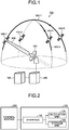
- FIG. 1 is a schematic diagram illustrating an example of a satellite system 700 configured by applying a scheduler apparatus 100 according to an embodiment of the present invention.
- the satellite system 700 includes the scheduler apparatus 100, a control station 200, an earth station 300, and satellites 400-1 to 400-N.
- the value of N is a natural number equal to or more than two.
- the satellites 400-1 to 400-N are artificial satellites such as communication satellites that provide communication services, optical satellites that observe the earth, or SAR satellites. Further, the satellites 400-1 to 400-N are orbiting satellites each orbiting on either of satellite orbits 500-1 and 500-2. In FIG.
- the satellite 400-1 to which a beam 600 is radiated from the earth station 300 can transmit data to the earth station 300.
- the satellites 400-1 to 400-N may be called satellites 400 when these satellites are not distinguished from one another, and the satellite orbits 500-1 and 500-2 may be called satellite orbits 500 when these orbits are not distinguished from each other.
- the satellite system 700 illustrated in FIG. 1 although the earth station 300, the control station 200, and the scheduler apparatus 100 are separate apparatuses from one another, this configuration is merely an example, and these apparatuses can be implemented as one apparatus.
- the configuration of the satellite system 700 illustrated in FIG. 1 is merely an example, and the number of the satellites 400, the number of the satellite orbits 500, and the number of the earth stations 300 are not limited to those in the configuration illustrated in FIG. 1 .
- the configuration of the satellite system 700 may be such that the satellite system 700 includes a data relay satellite on a geostationary orbit and the data relay satellite relays a data signal transmitted from the satellite 400 to transmit the signal to the earth station 300.
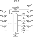
- FIG. 2 is a block diagram illustrating an example configuration of the scheduler apparatus 100 according to the present embodiment.
- the scheduler apparatus 100 includes an interface 110 that transmits and receives information to and from the control station 200 present outside the scheduler apparatus 100; a calculation unit 120 that determines the satellite 400 to which the earth station 300 is directed; and a storage unit 130 that stores information.
- the scheduler apparatus 100 in the satellite system 700 determines the satellite 400 to which the earth station 300 is directed, that is, the satellite 400 with which the earth station 300 communicates.
- the control station 200 controls the earth station 300 and the satellite 400.
- the control station 200 transmits, to the earth station 300 and the satellite 400, control information such as scheduling information output from the scheduler apparatus 100.
- FIG. 3 is a block diagram illustrating an example configuration of the satellite 400-1 according to the present embodiment. Because the satellites 400-1 to 400-N have an identical configuration to one another, the satellite 400-1 is described as an example.
- the satellite 400-1 includes reception antennas 401-1 to 401-4 receiving signals from the earth station 300 or a terminal (not illustrated) on the surface of the earth; transmission antennas 402-1 to 402-4 transmitting signals to the earth station 300 or a terminal (not illustrated) on the surface of the earth; and a telemetry-signal transmission antenna 403 that transmits a telemetry signal indicating an internal state of the satellite 400-1.
- the satellite 400-1 also includes phase shifters 404-1 to 404-4 each adjusting the phase of the signal transmitted from an associated one of the transmission antennas 402-1 to 402-4; a relay 405 that relays signals between the reception antennas 401-1 to 401-4 and the transmission antennas 402-1 to 402-4; and a telemetry-signal generation unit 406 that generates a telemetry signal.
- the satellite 400-1 further includes a buffer 407 that temporarily stores therein signals received by the reception antennas 401-1 to 401-4 and a control unit 408 that controls the relay 405 and the phase shifters 404-1 to 404-4.
- the reception antennas 401-1 to 401-4 may be called reception antennas 401 when these antennas are not distinguished from one another
- the transmission antennas 402-1 to 402-4 may be called transmission antennas 402 when these antennas are not distinguished from one another
- the phase shifters 404-1 to 404-4 may be called phase shifters 404 when these shifters are not distinguished from one another.
- the relay 405 is configured to include a filter, an amplifier, a demultiplexer, a switch, and a multiplexer, for example.
- the relay 405 may be configured to further include a modulator and a demodulator in addition to the filter and the like described above so as to allow regenerative relaying.
- the relay 405 is an existing satellite-borne relay.
- the buffer 407 is not an essential component in the satellite 400-1.
- the satellite 400-1 may have a configuration in which the reception antennas 401 and the relay 405 are directly connected to each other.
- the satellite 400-1 includes the buffer 407
- the satellite system 700 can be configured such that an optical line is used between the satellite 400 and the earth station 300 and between the satellite 400 and a data relay satellite or both an optical line and a wireless line are used between them.
- the configuration of each apparatus is varied depending on the mode of line between the apparatuses. However, the mode of line between the apparatuses is not specifically limited to any mode in the present embodiment.
- the transmission antennas 402 are phased array antennas.
- the satellite 400-1 can change the radiating direction of the signal transmitted from the transmission antenna 402, that is, the phased array antenna.
- the satellite 400-1 may be configured to include a general antenna and a movable reflecting mirror in place of the phase shifter 404 and the transmission antenna 402, that is, the phased array antenna, and change the radiating direction of a signal transmitted from the general antenna by changing the orientation of the reflecting mirror.
- the control unit 408 controls the phase shifter 404 in accordance with a control signal transmitted from the earth station 300, such as a control signal indicating the radiating direction of the signal transmitted from the transmission antenna 402, thereby changing the radiating direction of the signal to be transmitted.
- the telemetry-signal generation unit 406 generates, as internal information on the satellite 400-1, information on the data accumulation amount that indicates the amount of data accumulated in the buffer 407, for example.
- the telemetry-signal generation unit 406 transmits a telemetry signal including the generated internal information on the satellite 400-1 from the telemetry-signal transmission antenna 403 to the earth station 300.
- the telemetry-signal generation unit 406 may generate data type information indicating the type of data accumulated in the buffer 407 as the internal information and transmit the data type information in a state included in the telemetry signal. Further, the telemetry signal generation unit 406 may transmit two pieces of information, that is, the data accumulation amount and the type of data in a state included in the telemetry signal.
- the scheduler apparatus 100 is an apparatus that determines the satellite 400 to which the earth station 300 is directed on the basis of, for example, the amount of the accumulated data in the buffer 407 included in a telemetry signal that is transmitted from the satellite 400 and is acquired via the earth station 300 and the control station 200 and coordinate data of all the satellites 400 stored in advance in the storage unit 130.
- the scheduler apparatus 100 determines the satellite 400 to which the earth station 300 is directed and the timing at which the earth station 300 switches the directed satellite 400 such that the throughput of data received by the earth station 300 from the satellite 400 is maximized.
- the scheduler apparatus 100 generates a control signal indicating the satellite 400 to which the earth station 300 is directed and including the switching timing at which the earth station 300 switches the directed satellite 400, and transmits the control signal to the earth station 300.
- the earth station 300 uses the control signal received by the earth station itself and transmits the control signal to the satellite 400.
- the scheduler apparatus 100 does not necessarily need to store coordinate data of the satellites 400 in the storage unit 130 in advance. For example, in a case where the satellite 400 includes coordinate data of itself in a telemetry signal and transmits the telemetry signal to the earth station 300 regularly, it is possible that the scheduler apparatus 100 acquires the telemetry signal from the earth station 300 via the control station 200 and acquires the coordinate data of the satellite 400 from the telemetry signal.
- the method of acquiring the coordinate data of the satellite 400 by the scheduler apparatus 100 is not limited to those described above, and may be any appropriate method in accordance with its implementation.
- control signal indicating the satellite 400 to which the earth station 300 is directed
- the control signal has an appropriate format in accordance with the configuration of the satellite 400, while taking into consideration a control signal for controlling the phase shifter 404 of the satellite 400, a control signal for controlling the orientation of the reflecting mirror of the satellite 400, or the like.
- FIG. 4 is a flowchart illustrating an example of a process in which, in a case where the earth station 300 switches the directed satellite 400, the scheduler apparatus 100 according to the present embodiment determines the satellite 400 to which the earth station 300 is directed next and determines the timing at which the earth station 300 switches the directed satellite 400.
- the flowchart illustrated in FIG. 4 is merely an example, and the scheduler apparatus 100 may perform respective processes in a different order within a scope that an equivalent processing result can be obtained.
- the calculation unit 120 acquires, from the storage unit 130, position information on the satellite 400-1 to a satellite 400-M stored in advance (Step S1001).
- the calculation unit 120 may acquire telemetry signals from the earth station 300 and acquire the position information on the satellites 400-1 to 400-M from the telemetry signals.
- the value of M is a natural number equal to or more than two and equal to or less than N that satisfies a condition that the number of satellites 400 passing through the visible range of the earth station 300 until the satellite 400-1 moves out of that visible range is M-1.
- a satellite 400-2 to the satellite 400-M are the satellites 400 that pass through the visible range of the earth station 300 until the satellite 400-1 moves out of the visible range. It is also assumed that the satellite 400-1 is a first orbiting satellite, the satellites 400-2 to 400-M are second orbiting satellite candidates, and the satellite 400 which is among the satellites 400-2 to 400-M and to which the earth station 300 directed to the satellite 400-1 is directed next is a second orbiting satellite.
- the earth station 300 stores therein information on the data accumulation amounts stored in the buffers 407 of the satellites 400-1 to 400-M due to the telemetry signals received from the satellites 400-1 to 400-M.
- the calculation unit 120 acquires the data accumulation amounts stored in the buffers 407 in the satellites 400-1 to 400-M from the earth station 300 (Step S1002) .
- the calculation unit 120 acquires the amount of rain attenuation in the earth station 300 (Step S1003).
- the calculation unit 120 may derive the amount of rain attenuation on the basis of information on rainfall around the earth station 300, stored in advance in the storage unit 130, and the angle of elevation of the earth station 300 directed to the satellite 400-1, or may derive the amount of rain attenuation by using a pilot signal for indicating the rainfall state, the pilot signal being transmitted to the earth station 300 from the satellite 400-1.
- the calculation unit 120 derives an expected throughput in a case where the earth station 300 continues to be directed to the satellite 400-1 to which the earth station 300 is currently directed until the satellite 400-1 moves out of the visible range of the earth station 300, on the basis of the position information on the satellite 400-1 acquired at Step S1001 and the amount of rain attenuation in the earth station 300 acquired at Step S1003 (Step S1004) .
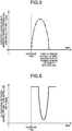
- FIG. 5 is a diagram illustrating an example of an expected throughput derived by the calculation unit 120 of the scheduler apparatus 100 according to the present embodiment in a case where the earth station 300 continues to be directed to the satellite 400-1 to which the earth station 300 is currently directed.
- the horizontal axis represents time and the vertical axis represents the magnitude of the throughput.
- the time period during which the calculation unit 120 derives an expected throughput in a case where the earth station 300 continues to be directed to the satellite 400-1 is from the current time to the time at which the satellite 400-1 moves out of the visible range of the earth station 300.
- the calculation unit 120 stores the derived expected throughput in the storage unit 130.
- the calculation unit 120 performs a process of a loop 1 (L1) to determine the timing at which the earth station 300 switches the directed satellite from the satellite 400-1 to which the earth station 300 is currently directed to another satellite 400, that is, any of the satellites 400-2 to 400-M.
- the loop 1 is a process repeated by the calculation unit 120, where the number of repetitions is equal to the number of the satellites 400 that pass through the visible range of the earth station 300 until the satellite 400-1 moves out of the visible range and is M-1 in this example.
- the calculation unit 120 selects one satellite 400-m from the satellites 400-2 to 400-M before starting the process of the loop 1.
- the value of m is a natural number equal to or more than two and equal to or less than M.
- the calculation unit 120 derives the elongation between the satellite 400-1 and the selected satellite 400-m as viewed from the earth station 300 (Step S1005).
- FIG. 6 is a diagram illustrating an example of the elongation that is derived by the calculation unit 120 of the scheduler apparatus 100 according to the present embodiment and is formed by the satellite 400-1 to which the earth station 300 is currently directed and the selected satellite 400-m as viewed from the earth station 300.
- the horizontal axis represents time and the vertical axis represents the magnitude of the elongation between the satellite 400-1 and the satellite 400-m as viewed from the earth station 300.
- the time at which the elongation is minimum means the time at which the satellite 400-1 and the satellite 400-m are closest to each other.
- the time at which the elongation is minimum is the time at which the time period required for switching is the shortest when the earth station 300 changes the directed satellite 400 from the satellite 400-1 to the satellite 400-m.
- the calculation unit 120 stores the derived elongation in the storage unit 130. When obtaining the elongation, the calculation unit 120 may use position information on the satellites 400-1 to 400-M stored in advance in the storage unit 130 or may use position information on the satellites 400-1 to 400-M included in telemetry signals.
- the calculation unit 120 derives an expected throughput in a case where the earth station 300 is directed to the satellite 400-m on the basis of the position information on the satellite 400-m, the angle of elevation of the earth station 300 obtained from the position information, and the amount of rain attenuation in the earth station 300 (Step S1006).
- FIG. 7 is a diagram illustrating an example of an expected throughput derived by the calculation unit 120 of the scheduler apparatus 100 according to the present embodiment in a case where the earth station 300 is directed to the selected satellite 400-m.
- the calculation unit 120 stores, in the storage unit 130, the expected throughput that has been derived. Because the earth station 300 is currently directed to the satellite 400-1, the earth station 300 cannot receive a pilot signal for notifying the earth station 300 of the rainfall state directly from the satellite 400-m.
- the calculation unit 120 may obtain the amount of rain attenuation in a case where the earth station 300 is directed to the satellite 400-m, from the rainfall state included in a pilot signal that the earth station 300 received from the satellite 400-1 and the elongation between the satellite 400-1 and the satellite 400-m or from rainfall information stored in advance in the storage unit 130 and the elongation between the satellite 400-1 and the satellite 400-m.
- the calculation unit 120 derives the switching timing of the directed satellite 400 at which the throughput of the earth station 300 is maximum on the basis of the expected throughput in a case where the earth station 300 continues to be directed to the satellite 400-1 derived at Step S1004, the elongation between the satellite 400-1 and the satellite 400-m derived at Step S1005, and the expected throughput in a case where the earth station 300 is directed to the satellite 400-m derived at Step S1006 (Step S1007).
- the calculation unit 120 derives, as the switching timing of the directed satellite 400, the timing at which the total value of the time integral value of the expected throughput in a case where the earth station 300 continues to be directed to the satellite 400-1 derived at Step S1004 and the time integral value of the expected throughput in a case where the earth station 300 is directed to the satellite 400-m derived at Step S1006 is maximum, for example.
- the calculation unit 120 estimates the amount of data that the earth station 300 can finally receive, and then determines the timing at which the maximum throughput is obtained in the earth station 300.
- FIG. 8 is a schematic diagram illustrating a method of deriving, by the calculation unit 120 of the scheduler apparatus 100 according to the present embodiment, the timing at which the earth station 300 switches a directed satellite.
- the thick line part denotes the throughput that the earth station 300 obtains from the satellite 400-1 and the satellite 400-m
- the time integral value of the thick line part represents the total value of the capacity of data received by the earth station 300 from the satellite 400-1 and the satellite 400-m.
- the time during which the throughput of the earth station 300 is zero represents the time required for switching from the satellite 400-1 to the satellite 400-m by the earth station 300.
- the earth station 300 cannot receive data either from the satellite 400-1 or the satellite 400-m.
- the calculation unit 120 derives the time integral value of the throughput for all the conceivable switching timings in a round-robin manner, and can select one of all the switching timings, at which the time integral value of the throughput is maximum, as the timing of switching the directed satellite.
- the method of deriving the switching timing is not limited thereto.
- the calculation unit 120 can determine the time required for switching on the basis of the elongation derived at Step S1005, that is, the position information on the satellite 400-1 and the satellite 400-m.
- the calculation unit 120 selects an unselected satellite 400-m from the satellites 400-2 to 400-M.
- the calculation unit 120 performs the process of the loop 1 on all the candidates of the satellite 400 to which the earth station 300 is directed next, that is, the satellites 400-2 to 400-M.
- the calculation unit 120 derives the switching timing at which the throughput of the earth station 300 is maximum and the maximum throughput obtained in a case where the directed satellite 400 is switched at that switching timing, for each of the satellites 400-2 to 400-M.
- the calculation unit 120 determines, among the satellites 400-2 to 400-M, the satellite 400 to which the earth station 300 switches a directed satellite from the satellite 400-1, on the basis of the switching timing and the maximum throughput for each candidate of the satellite 400 to which the earth station 300 is directed next, that is, each of the satellites 400-2 to 400-M, derived in the process of the loop 1 (Step S1008).
- the calculation unit 120 determines the satellite 400 to which the earth station 300 directed to the satellite 400-1 is directed next and the switching timing at which the earth station 300 switches a directed satellite from the satellite 400-1 to the satellite 400 to which the earth station 300 is directed next, on the basis of the times required for switching by the earth station 300 from the satellite 400-1 to the satellites 400-2 to 400-M, a future expected throughout between the earth station 300 and the satellite 400-1, and a future expected throughput between the earth station 300 and each of the satellites 400-2 to 400-M.
- the calculation unit 120 can determine the satellite 400 to which the earth station 300 is directed next and the switching timing by various methods. For example, the calculation unit 120 may simply select the satellite 400 that provides the maximum throughput and the timing of switching to that satellite 400. Further, the calculation unit 120 may select, as the satellite 400 to which the earth station 300 is directed next, the satellite 400 in which the data accumulation amount is maximum on the basis of the data accumulation amount in the buffer 407 of each satellite 400 acquired at Step S1002. The calculation unit 120 determines the directed satellite 400 while taking the data accumulation amount in the buffer 407 of each satellite 400 into consideration.
- the calculation unit 120 may select the satellite 400 that relays data with a higher priority as the satellite 400 to which the earth station 300 is directed next, on the basis of the data type.
- the calculation unit 120 determines the directed satellite 400 while taking the priority of data accumulated in the buffer 407 of each satellite 400 into consideration. Further, the calculation unit 120 may select the satellite 400 to which the earth station 300 is directed next by using a plurality of elements described above including the magnitude of the throughput, the data accumulation amount, and the data type.
- the calculation unit 120 generates a control signal indicating the satellite 400 selected at Step S1008 to which the earth station 300 is directed next and including the timing of switching to that satellite 400 (Step S1009).
- the control signal is a signal indicating the satellite 400 and the radiating angle of the earth station 300, for example.
- the control signal can have various formats in accordance with the configurations of the satellite 400 and the earth station 300.
- the calculation unit 120 can generate a control signal in a format of control information for determining the satellite 400 and the direction of a beam from the earth station 300 for each time.
- the interface 110 then transmits the control signal generated by the calculation unit 120 at Step S1009 to the earth station 300 and the satellites 400-1 to 400-M (Step S1010). It suffices that the interface 110 transmits the control signal to the earth station 300 via the control station 200 through a land line or the like. Further, as for the control signal to the satellite 400-1, the interface 110 may transmit the control signal via the earth station 300 that is directed to the satellite 400-1. As for the control signal to each of the satellites 400-2 to 400-M, in a case where there is an earth station that is other than the earth station 300 and is directed to the satellite, the interface 110 may transmit the control signal via that earth station.
- the interface 110 transmits the control signals to the satellites 400-2 to 400-M via the data relay satellite.
- the interface 110 can transmit the control signals by various methods in accordance with the network configuration of the satellite system 700. In the flowchart of FIG. 4 , it is assumed that the process in the calculation unit 120 is a calculating step and the process in the interface 110 is a transmitting step.
- FIG. 9 is a sequence diagram illustrating signals transmitted and received in a process in which the scheduler apparatus 100 according to the present embodiment determines the satellite 400 to which the earth station 300 is directed next and the timing of switching the directed satellite 400. While it is conceivable that the processes in the flowchart illustrated in FIG. 4 are performed by the scheduler apparatus 100 in accordance with the sequence diagram illustrated in FIG. 9 , this is not a limitation.
- the scheduler apparatus 100 determines the satellite 400 to which the earth station 300 is directed next and the switching timing and generates a control signal, immediately after acquiring position information and rain attenuation information. Alternatively, the scheduler apparatus 100 may determine the satellite 400 to which the earth station 300 is directed next and the switching timing and generate the control signal with any period.
- the calculation unit 120 takes into account only a satellite 400 to which the earth station 300 is directed next, this is not a limitation. In an environment where change of the rain attenuation amount over time is small, such as when it is fine weather, the calculation unit 120 may take up to the second next or the third next switching destination satellite 400 to which the earth station 300 is directed into consideration and determine the satellite 400 that is a switching destination and the switching timing such that the maximum throughput of the earth station 300 is obtained.
- the satellite system 700 can include a plurality of earth stations 300 as described above.
- the calculation unit 120 may derive the amount of rain attenuation in each of the earth stations 300 on the basis of information on the rainfall state included in a pilot signal received from the satellite 400, and determine the earth station 300 the amount of rain attenuation of which is small as the earth station 300 to which the satellite 400 transmits data.
- the satellite 400 can transmit data to the earth station 300 the amount of rain attenuation of which is small.
- the interface 110 is implemented by an interface circuit and the like.
- the interface circuit is a network interface card, for example.
- the storage unit 130 is implemented by a memory.
- the calculation unit 120 is implemented by a processing circuit. That is, the scheduler apparatus 100 includes a processing circuit that determines the satellite 400 to which the earth station 300 is directed next and the timing of switching the directed satellite 400.
- the processing circuit may be a central processing unit (CPU) that executes a program stored in a memory and the memory, or may be dedicated hardware.
- FIG. 10 is a diagram illustrating an example of a case where a processing circuit of the scheduler apparatus 100 according to the present embodiment is configured from a CPU and a memory.
- a network interface card 91 implements the interface 110 described above.
- the processing circuit is configured from a CPU 92 and a memory 93
- functions of the processing circuit of the scheduler apparatus 100 are implemented by software, firmware, or a combination of software and firmware.
- the software or the firmware is described as a program and is stored in the memory 93.
- the functions of the processing circuit are implemented by the CPU 92 reading and executing the program stored in the memory 93.
- the processing circuit includes the memory 93 for storing therein programs, which will eventually execute determination of the satellite 400 to which the earth station 300 is directed next and the timing of switching the directed satellite 400. Further, it can be said that these programs cause a computer to perform a procedure and a method of the scheduler apparatus 100.
- the CPU 92 may be a processing device, a calculation device, a microprocessor, a microcomputer, a processor, a digital signal processor (DSP), or the like.
- the memory 93 corresponds to a nonvolatile or volatile semiconductor memory such as a random access memory (RAM), a read only memory (ROM), a flash memory, an erasable programmable memory (EPROM), or an eclectically EPROM (EEPROM), a magnetic disk, a flexible disk, an optical disk, a compact disk, a mini disk, or a digital versatile disc (DVD).
- RAM random access memory
- ROM read only memory
- EPROM erasable programmable memory
- EEPROM eclectically EPROM
- the memory 93 may be common to a memory that implements the storage unit 130.
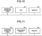
- FIG. 11 is a diagram illustrating an example of a case where the processing circuit of the scheduler apparatus 100 according to the present embodiment is configured by dedicated hardware.
- a processing circuit 94 illustrated in FIG. 11 corresponds to, for example, a single circuit, a composite circuit, a programmed processor, a parallel programmed processor, an application specific integrated circuit (ASIC), an field programmable gate array (FPGA), or a combination of these elements.
- the respective functions of the scheduler apparatus 100 can be realized by the processing circuit 94 for each function independently or can be realized by the processing circuit 94 collectively.
- the processing circuit can realize the respective functions described above by dedicated hardware, software, firmware, or a combination of these elements.
- the calculation unit 120 determines the satellite 400 to which the earth station 300 is directed next and the timing of switching a directed satellite to the next satellite 400, on the basis of position information on the satellites 400 and the amount of rain attenuation in the earth station 300 in such a manner that the throughput of the earth station 300 is maximized.
Landscapes
- Engineering & Computer Science (AREA)
- Computer Networks & Wireless Communication (AREA)
- Signal Processing (AREA)
- Physics & Mathematics (AREA)
- Astronomy & Astrophysics (AREA)
- Aviation & Aerospace Engineering (AREA)
- General Physics & Mathematics (AREA)
- Radio Relay Systems (AREA)
Claims (12)
- Zeitplanungsvorrichtung (100), umfassend:eine Berechnungseinheit (120), die eingerichtet ist, für jeden zweiten umlaufenden Satelliten-Kandidaten (400-2 bis 400-M) einer Vielzahl von zweiten umlaufenden Satelliten-Kandidaten (400-2 bis 400-M) einen Umschaltzeitpunkt, zu dem eine Bodenstation (300) einen gerichteten Satelliten von einem ersten umlaufenden Satelliten (400-1) zu dem zweiten umlaufenden Satelliten-Kandidaten (400-2 bis 400-M) umschaltet auf Grundlage einer Zeit, die für das Umschalten von dem ersten umlaufenden Satelliten (400-1) zu dem zweiten umlaufenden Satelliten-Kandidaten (400-2 bis 400-M) erforderlich ist, eines zukünftigen erwarteten Durchsatzes zwischen der Bodenstation (300) und dem ersten umlaufenden Satelliten (400-1) und eines zukünftigen erwarteten Durchsatzes zwischen der Bodenstation (300) und dem zweiten umlaufenden Satelliten-Kandidaten (400-2 bis 400-M), abzuleiten, und einen zweiten umlaufenden Satelliten auf Grundlage des Umschaltzeitpunkts und eines maximalen Durchsatzes zwischen der Bodenstation (300) und jedem zweiten umlaufenden Satelliten-Kandidaten (400-2 bis 400-M) zu bestimmen, wobei der erste umlaufende Satellit (400-1) ein umlaufender Satellit ist, auf den die Bodenstation (300) aktuell gerichtet ist, und jeder zweite umlaufende Satelliten-Kandidat ein umlaufender Satellit ist, der ein Kandidat für den zweiten umlaufenden Satelliten ist, der ein umlaufender Satellit ist, auf den eine Bodenstation (300) als nächstes gerichtet ist; undeine Schnittstelle (110), die eingerichtet ist, Informationen zu dem zweiten durch die Berechnungseinheit (120) bestimmten umlaufenden Satelliten und den durch die Berechnungseinheit (120) abgeleiteten Umschaltzeitpunkt, der dem zweiten umlaufenden Satelliten entspricht, an die Bodenstation (300) zu übertragen.
- Zeitplanungsvorrichtung (100) nach Anspruch 1, wobei die Berechnungseinheit (120) eingerichtet ist, einen zukünftigen erwarteten Durchsatz zwischen der Bodenstation (300) und dem umlaufenden Satelliten auf Grundlage von Positionsinformationen zu dem umlaufenden Satelliten und einer Regenabschwächungsmenge in der Bodenstation (300) für jeden umlaufenden Satelliten zu bestimmen.
- Zeitplanungsvorrichtung (100) nach Anspruch 1 oder 2, wobei die Berechnungseinheit (120) eingerichtet ist, die zum Umschalten erforderliche Zeit auf Grundlage von Positionsinformationen zu dem ersten umlaufenden Satelliten (400-1) und Positionsinformationen zu dem zweiten umlaufenden Satelliten-Kandidaten (400-2 bis 400-M) zu bestimmen.
- Zeitplanungsvorrichtung (100) nach einem der Ansprüche 1 bis 3, wobei die Schnittstelle (110) eingerichtet ist, die Informationen zu dem umlaufenden Satelliten und dem Umschaltzeitpunkt als Steuerungsinformationen zum Bestimmen des umlaufenden Satelliten und einer Richtung eines Strahls von der Bodenstation (300) für jede Zeit zu übertragen.
- Zeitplanungsvorrichtung (100) nach Anspruch 2, ferner umfassend eine Speichereinheit (130), die eingerichtet ist, Informationen zu einer Niederschlagsmenge zu speichern, wobei
die Berechnungseinheit (120) eingerichtet ist, die Regenabschwächungsmenge in der Bodenstation (300) für jeden umlaufenden Satelliten auf Grundlage der Informationen zu der Niederschlagsmenge und eines Höhenwinkels der Bodenstation (300) in Bezug auf den umlaufenden Satelliten abzuleiten. - Zeitplanungsvorrichtung (100) nach Anspruch 2, wobei die Berechnungseinheit (120) eingerichtet ist, die Regenabschwächungsmenge in der Bodenstation (300) für jeden umlaufenden Satelliten auf Grundlage von Informationen zu einem Niederschlagszustand, der in einem Pilotsignal enthalten ist, das durch die Bodenstation (300) von dem ersten umlaufenden Satelliten (400-1) empfangen wird, und eines Höhenwinkels der Bodenstation (300) in Bezug auf den umlaufenden Satelliten abzuleiten.
- Zeitplanungsvorrichtung (100) nach einem der Ansprüche 1 bis 6, wobei die Berechnungseinheit (120) eingerichtet ist, den Umschaltzeitpunkt auf Grundlage eines Zeitintegralwerts des zukünftigen erwarteten Durchsatzes zwischen der Bodenstation (300) und dem ersten umlaufenden Satelliten (400-1) und eines Zeitintegralwerts des zukünftigen erwarteten Durchsatzes zwischen der Bodenstation (300) und dem zweiten umlaufenden Satelliten-Kandidaten (400-2 bis 400-M) abzuleiten.
- Zeitplanungsvorrichtung (100) nach Anspruch 7, wobei die Berechnungseinheit (120) eingerichtet ist, als den Umschaltzeitpunkt einen Zeitpunkt abzuleiten, zu dem ein Gesamtwert des Zeitintegralwerts des zukünftigen erwarteten Durchsatzes zwischen der Bodenstation (300) und dem ersten umlaufenden Satelliten (400-1) und des Zeitintegralwerts des zukünftigen erwarteten Durchsatzes zwischen der Bodenstation (300) und dem zweiten umlaufenden Satelliten-Kandidaten (400-2 bis 400-M) maximal ist.
- Zeitplanungsvorrichtung (100) nach Anspruch 8, wobei die Berechnungseinheit (120) eingerichtet ist, für jeden zweiten umlaufenden Satelliten-Kandidaten (400-2 bis 400-M) einen maximalen Gesamtwert des Zeitintegralwerts des zukünftigen erwarteten Durchsatzes zwischen der Bodenstation (300) und dem ersten umlaufenden Satelliten (400-1) und des Zeitintegralwerts des zukünftigen erwarteten Durchsatzes zwischen der Bodenstation (300) und dem zweiten umlaufenden Satelliten-Kandidaten (400-2 bis 400-M) abzuleiten und den zweiten umlaufenden Satelliten-Kandidaten (400-2 bis 400-M), mit dem der maximale Gesamtwert maximal ist, als den zweiten umlaufenden Satelliten zu bestimmen.
- Zeitplanungsvorrichtung (100) nach Anspruch 8, wobei
in einem Modus, in dem ein Netzwerk eine Vielzahl von Bodenstationen (300) umfasst, die Berechnungseinheit (120) eingerichtet ist, eine Regenabschwächungsmenge in der Vielzahl von Bodenstationen (300) auf Grundlage von Informationen über einen Niederschlagszustand, der in einem von dem umlaufenden Satelliten empfangenen Pilotsignal enthalten ist, abzuleiten, und eine Bodenstation (300), in der eine Regenabschwächungsmenge klein ist, als eine Bodenstation (300) bestimmt, die ein Ziel von Daten ist, die von dem umlaufenden Satelliten übertragen werden. - Zeitplanungsverfahren, umfassend:einen Berechnungsschritt des Ableitens, für jeden zweiten umlaufenden Satelliten-Kandidaten (400-2 bis 400-M) einer Vielzahl von zweiten umlaufenden Satelliten-Kandidaten (400-2 bis 400-M), einen Umschaltzeitpunkt, zu dem eine Bodenstation (300) einen gerichteten Satelliten von einem ersten umlaufenden Satelliten (400-1) zu dem zweiten umlaufenden Satelliten-Kandidaten (400-2 bis 400-M) umschaltet auf Grundlage einer Zeit, die für das Umschalten von dem ersten umlaufenden Satelliten (400-1) zu dem zweiten umlaufenden Satelliten-Kandidaten (400-2 bis 400-M) erforderlich ist, eines zukünftigen erwarteten Durchsatzes zwischen der Bodenstation (300) und dem ersten umlaufenden Satelliten (400-1), und eines zukünftigen erwarteten Durchsatzes zwischen der Bodenstation (300) und dem zweiten umlaufenden Satelliten-Kandidaten (400-2 bis 400-M), und des Bestimmens eines zweiten umlaufenden Satelliten auf Grundlage des Umschaltzeitpunkts und eines maximalen Durchsatzes zwischen der Bodenstation (300) und jedem zweiten umlaufenden Satelliten-Kandidaten (400-2 bis 400-M), wobei der erste umlaufende Satellit (400-1) ein umlaufender Satellit ist, auf den die Bodenstation (300) aktuell gerichtet ist, und jeder zweite umlaufende Satelliten-Kandidat ein umlaufender Satellit ist, der ein Kandidat für den zweiten umlaufenden Satelliten ist, der ein umlaufender Satellit ist, auf den eine Bodenstation (300) als nächstes gerichtet ist, wo der Berechnungsschritt durch eine Berechnungseinheit (120) durchgeführt wird; undeinen Übertragungsschritt des Übertragens von Informationen zu dem zweiten im Berechnungsschritt bestimmten umlaufenden Satelliten und den im Berechnungsschritt abgeleiteten Umschaltzeitpunkt, der dem zweiten umlaufenden Satelliten entspricht, an die Bodenstation (300), wo der Übertragungsschritt durch eine Schnittstelle (110) durchgeführt wird.
- Computerlesbares Aufzeichnungsmedium einer Zeitplanungsvorrichtung (100), wobei das Aufzeichnungsmedium darin ein Programm speichert, um einen Prozessor zu veranlassen, auszuführen: einen Prozess des: Ableitens, für jeden zweiten umlaufenden Satelliten-Kandidaten (400-2 bis 400-M) einer Vielzahl von zweiten umlaufenden Satelliten-Kandidaten (400-2 bis 400-M), eines Umschaltzeitpunkts, zu dem eine Bodenstation (300) einen gerichteten Satelliten von einem ersten umlaufenden Satelliten (400-1) zu dem zweiten umlaufenden Satelliten-Kandidaten (400-2 bis 400-M) umschaltet auf Grundlage einer Zeit, die für das Umschalten von dem ersten umlaufenden Satelliten (400-1) zu dem zweiten umlaufenden Satelliten-Kandidaten (400-2 bis 400-M) erforderlich ist, eines zukünftigen erwarteten Durchsatzes zwischen der Bodenstation (300) und dem ersten umlaufenden Satelliten (400-1), und eines zukünftigen erwarteten Durchsatzes zwischen der Bodenstation (300) und dem zweiten umlaufenden Satelliten-Kandidaten (400-2 bis 400-M), und Bestimmens eines zweiten umlaufenden Satelliten auf Grundlage des Umschaltzeitpunkts und eines maximalen Durchsatzes zwischen der Bodenstation (300) und jedem zweiten umlaufenden Satelliten-Kandidaten (400-2 bis 400-M), wobei der erste umlaufende Satellit (400-1) ein umlaufender Satellit ist, auf den die Bodenstation (300) aktuell gerichtet ist, und jeder zweite umlaufende Satelliten-Kandidat ein umlaufender Satellit ist, der ein Kandidat für den zweiten umlaufenden Satelliten ist, der ein umlaufender Satellit ist, auf den eine Bodenstation (300) als nächstes gerichtet ist.
Applications Claiming Priority (1)
| Application Number | Priority Date | Filing Date | Title |
|---|---|---|---|
| PCT/JP2017/004240 WO2018142618A1 (ja) | 2017-02-06 | 2017-02-06 | スケジューラ装置およびスケジューリング方法 |
Publications (3)
| Publication Number | Publication Date |
|---|---|
| EP3567748A1 EP3567748A1 (de) | 2019-11-13 |
| EP3567748A4 EP3567748A4 (de) | 2020-01-15 |
| EP3567748B1 true EP3567748B1 (de) | 2021-03-24 |
Family
ID=63039444
Family Applications (1)
| Application Number | Title | Priority Date | Filing Date |
|---|---|---|---|
| EP17895421.0A Active EP3567748B1 (de) | 2017-02-06 | 2017-02-06 | Planungsvorrichtung und planungsverfahren |
Country Status (5)
| Country | Link |
|---|---|
| US (1) | US10727935B2 (de) |
| EP (1) | EP3567748B1 (de) |
| JP (1) | JP6524361B2 (de) |
| CA (1) | CA3050860C (de) |
| WO (1) | WO2018142618A1 (de) |
Families Citing this family (4)
| Publication number | Priority date | Publication date | Assignee | Title |
|---|---|---|---|---|
| US10863404B2 (en) * | 2018-11-20 | 2020-12-08 | Hughes Network Systems, Llc | Satellite load balancing |
| JP7436194B2 (ja) * | 2019-12-06 | 2024-02-21 | キヤノン電子株式会社 | 衛星追尾システム、衛星追尾方法、およびプログラム |
| US20210320715A1 (en) * | 2020-04-10 | 2021-10-14 | John Moroney | Hybrid dual-band satellite communication system |
| CN114476131B (zh) * | 2021-11-09 | 2023-03-10 | 浙江时空道宇科技有限公司 | 一种卫星测控调度方法、装置及存储介质 |
Family Cites Families (19)
| Publication number | Priority date | Publication date | Assignee | Title |
|---|---|---|---|---|
| US6377208B2 (en) * | 1997-02-21 | 2002-04-23 | Hughes Electronics Corporation | Method and system for determining a position of a transceiver unit utilizing two-way ranging in a polystatic satellite configuration |
| US5946603A (en) * | 1997-04-25 | 1999-08-31 | Motorola, Inc. | Method and apparatus to respond to a blockage environment in a communication system |
| WO1998051022A1 (en) * | 1997-05-02 | 1998-11-12 | Uscx | High latitude geostationary satellite system |
| JP2000315972A (ja) * | 1999-05-06 | 2000-11-14 | Nec Corp | 衛星通信システム及びそのハンドオーバ処理方法 |
| JP2003318794A (ja) * | 2002-04-26 | 2003-11-07 | Hitachi Ltd | 人工衛星からの信号の受信方法,人工衛星からの信号の受信装置,送信方法及び人工衛星と情報を授受する情報システム |
| JP2004140721A (ja) | 2002-10-21 | 2004-05-13 | Hitachi Ltd | 人工衛星を利用した信号の受信方法、サービスの提供方法、人工衛星の制御方法、および受信端末ならびに人工衛星を制御する装置 |
| KR100705579B1 (ko) * | 2005-08-01 | 2007-04-10 | 삼성전자주식회사 | 복합망을 이용한 핸드오프 구현 시스템 및 그 방법 |
| US20070135040A1 (en) * | 2005-12-12 | 2007-06-14 | Draim John E | Methods for effecting seamless handover and enhancing capacity in elliptical orbit satellite communications systems |
| JP2014053751A (ja) * | 2012-09-07 | 2014-03-20 | Takeshi Hatsuda | 複数衛星間の動的切り替えを行うサテライトダイバーシティ(D・Sat−D)方式 |
| US8712321B1 (en) * | 2013-01-07 | 2014-04-29 | Viasat, Inc. | Satellite fleet deployment |
| EP3120467B1 (de) * | 2014-03-19 | 2019-02-20 | Hughes Network Systems, LLC | Vorrichtung und verfahren zur effizienten übergabe für leo-satellitensysteme |
| US20170127323A1 (en) * | 2014-04-27 | 2017-05-04 | Novelsat Ltd. | Handover between satellites using a single modem |
| US9888426B2 (en) | 2015-05-01 | 2018-02-06 | Qualcomm Incorporated | Handoff for satellite communication |
| WO2017048339A1 (en) * | 2015-06-16 | 2017-03-23 | King Abdulaziz City Of Science And Technology | Systems and methods for remote sensing of the earth from space |
| US10177837B2 (en) * | 2015-06-17 | 2019-01-08 | Hughes Network Systems, Llc | Approaches for high speed global packet data services for LEO/MEO satellite systems |
| US9681337B2 (en) * | 2015-08-05 | 2017-06-13 | Qualcomm Incorporated | Satellite-to-satellite handoff in satellite communications system |
| US10476583B2 (en) * | 2015-08-13 | 2019-11-12 | Viasat, Inc. | Managed time division duplexed baseband signaling |
| US10244453B2 (en) * | 2015-10-13 | 2019-03-26 | Qualcomm Incorporated | Method and apparatus for inter-satellite handovers in low-earth orbit (LEO) satellite systems |
| JP6937750B2 (ja) * | 2015-10-28 | 2021-09-22 | ワールドビュー・サテライツ・リミテッド | 増大した通信容量を有する衛星システムおよび衛星システムの容量を増大させるための方法 |
-
2017
- 2017-02-06 EP EP17895421.0A patent/EP3567748B1/de active Active
- 2017-02-06 WO PCT/JP2017/004240 patent/WO2018142618A1/ja not_active Ceased
- 2017-02-06 CA CA3050860A patent/CA3050860C/en active Active
- 2017-02-06 US US16/476,355 patent/US10727935B2/en active Active
- 2017-02-06 JP JP2018565228A patent/JP6524361B2/ja active Active
Non-Patent Citations (1)
| Title |
|---|
| None * |
Also Published As
| Publication number | Publication date |
|---|---|
| JP6524361B2 (ja) | 2019-06-05 |
| WO2018142618A1 (ja) | 2018-08-09 |
| US20200044731A1 (en) | 2020-02-06 |
| EP3567748A4 (de) | 2020-01-15 |
| EP3567748A1 (de) | 2019-11-13 |
| JPWO2018142618A1 (ja) | 2019-07-11 |
| US10727935B2 (en) | 2020-07-28 |
| CA3050860A1 (en) | 2018-08-09 |
| CA3050860C (en) | 2019-12-24 |
Similar Documents
| Publication | Publication Date | Title |
|---|---|---|
| JP7060585B2 (ja) | 衛星通信システムにおける近隣セルリスト | |
| EP3332489B1 (de) | Übergabe von satellit zu satellit in einem satellitenkommunikationssystem | |
| EP3567748B1 (de) | Planungsvorrichtung und planungsverfahren | |
| US11044008B2 (en) | Systems for mitigating service interrupts in satellite systems | |
| US12401414B2 (en) | Method for handover of satellite base station, terminal, satellite base station, and storage medium | |
| EP4087156A1 (de) | Verfahren, vorrichtung und medium zur verarbeitung eines satellitenstrahlversatzes | |
| WO2018125334A9 (en) | Method and system for dealing with antenna blockage in a low earth orbit constellation | |
| US20230396330A1 (en) | Beam selection in non-terrestrial networks | |
| KR102613223B1 (ko) | 반구형태의 안테나 어레이를 포함하는 저궤도 위성신호 송수신 시스템 및 그 방법 | |
| US20260039374A1 (en) | Communication control apparatus, communication control method, communication control program, communication control system, communication relay satellite, and satellite system | |
| CN116867013A (zh) | 卫星基站切换的方法、卫星基站和存储介质 | |
| CN110890915A (zh) | 用于与多个航天器进行并发通信的地基天线 | |
| AU2017218619A1 (en) | Antenna array for aeronautical communications | |
| JP4575182B2 (ja) | 衛星通信用端末及び管理局 | |
| WO2023027675A1 (en) | System and method for cell handover from non-terrestrial networks to terrestrial networks | |
| JPWO2017013698A1 (ja) | ビーム配置装置およびビーム配置方法 | |
| WO2026053619A1 (ja) | 情報処理装置、情報処理方法、及びプログラム | |
| RU2673060C1 (ru) | Спутниковый ретранслятор | |
| JPH08331033A (ja) | 衛星及び地上通信回線の設定方法、移動局の位置決定と登録方法 | |
| HK1249971B (zh) | 卫星通信系统中的卫星到卫星切换的方法及用户终端 |
Legal Events
| Date | Code | Title | Description |
|---|---|---|---|
| STAA | Information on the status of an ep patent application or granted ep patent |
Free format text: STATUS: THE INTERNATIONAL PUBLICATION HAS BEEN MADE |
|
| PUAI | Public reference made under article 153(3) epc to a published international application that has entered the european phase |
Free format text: ORIGINAL CODE: 0009012 |
|
| STAA | Information on the status of an ep patent application or granted ep patent |
Free format text: STATUS: REQUEST FOR EXAMINATION WAS MADE |
|
| 17P | Request for examination filed |
Effective date: 20190704 |
|
| AK | Designated contracting states |
Kind code of ref document: A1 Designated state(s): AL AT BE BG CH CY CZ DE DK EE ES FI FR GB GR HR HU IE IS IT LI LT LU LV MC MK MT NL NO PL PT RO RS SE SI SK SM TR |
|
| AX | Request for extension of the european patent |
Extension state: BA ME |
|
| A4 | Supplementary search report drawn up and despatched |
Effective date: 20191213 |
|
| RIC1 | Information provided on ipc code assigned before grant |
Ipc: H04B 7/155 20060101AFI20191209BHEP Ipc: H04B 7/185 20060101ALI20191209BHEP Ipc: H04W 36/00 20090101ALI20191209BHEP |
|
| STAA | Information on the status of an ep patent application or granted ep patent |
Free format text: STATUS: EXAMINATION IS IN PROGRESS |
|
| DAV | Request for validation of the european patent (deleted) | ||
| DAX | Request for extension of the european patent (deleted) | ||
| 17Q | First examination report despatched |
Effective date: 20200512 |
|
| GRAP | Despatch of communication of intention to grant a patent |
Free format text: ORIGINAL CODE: EPIDOSNIGR1 |
|
| STAA | Information on the status of an ep patent application or granted ep patent |
Free format text: STATUS: GRANT OF PATENT IS INTENDED |
|
| INTG | Intention to grant announced |
Effective date: 20200918 |
|
| GRAS | Grant fee paid |
Free format text: ORIGINAL CODE: EPIDOSNIGR3 |
|
| GRAA | (expected) grant |
Free format text: ORIGINAL CODE: 0009210 |
|
| STAA | Information on the status of an ep patent application or granted ep patent |
Free format text: STATUS: THE PATENT HAS BEEN GRANTED |
|
| AK | Designated contracting states |
Kind code of ref document: B1 Designated state(s): AL AT BE BG CH CY CZ DE DK EE ES FI FR GB GR HR HU IE IS IT LI LT LU LV MC MK MT NL NO PL PT RO RS SE SI SK SM TR |
|
| REG | Reference to a national code |
Ref country code: GB Ref legal event code: FG4D |
|
| REG | Reference to a national code |
Ref country code: CH Ref legal event code: EP |
|
| REG | Reference to a national code |
Ref country code: IE Ref legal event code: FG4D |
|
| REG | Reference to a national code |
Ref country code: AT Ref legal event code: REF Ref document number: 1375566 Country of ref document: AT Kind code of ref document: T Effective date: 20210415 Ref country code: DE Ref legal event code: R096 Ref document number: 602017035475 Country of ref document: DE |
|
| REG | Reference to a national code |
Ref country code: LT Ref legal event code: MG9D |
|
| PG25 | Lapsed in a contracting state [announced via postgrant information from national office to epo] |
Ref country code: BG Free format text: LAPSE BECAUSE OF FAILURE TO SUBMIT A TRANSLATION OF THE DESCRIPTION OR TO PAY THE FEE WITHIN THE PRESCRIBED TIME-LIMIT Effective date: 20210624 Ref country code: FI Free format text: LAPSE BECAUSE OF FAILURE TO SUBMIT A TRANSLATION OF THE DESCRIPTION OR TO PAY THE FEE WITHIN THE PRESCRIBED TIME-LIMIT Effective date: 20210324 Ref country code: GR Free format text: LAPSE BECAUSE OF FAILURE TO SUBMIT A TRANSLATION OF THE DESCRIPTION OR TO PAY THE FEE WITHIN THE PRESCRIBED TIME-LIMIT Effective date: 20210625 Ref country code: HR Free format text: LAPSE BECAUSE OF FAILURE TO SUBMIT A TRANSLATION OF THE DESCRIPTION OR TO PAY THE FEE WITHIN THE PRESCRIBED TIME-LIMIT Effective date: 20210324 Ref country code: NO Free format text: LAPSE BECAUSE OF FAILURE TO SUBMIT A TRANSLATION OF THE DESCRIPTION OR TO PAY THE FEE WITHIN THE PRESCRIBED TIME-LIMIT Effective date: 20210624 |
|
| PG25 | Lapsed in a contracting state [announced via postgrant information from national office to epo] |
Ref country code: RS Free format text: LAPSE BECAUSE OF FAILURE TO SUBMIT A TRANSLATION OF THE DESCRIPTION OR TO PAY THE FEE WITHIN THE PRESCRIBED TIME-LIMIT Effective date: 20210324 Ref country code: LV Free format text: LAPSE BECAUSE OF FAILURE TO SUBMIT A TRANSLATION OF THE DESCRIPTION OR TO PAY THE FEE WITHIN THE PRESCRIBED TIME-LIMIT Effective date: 20210324 Ref country code: SE Free format text: LAPSE BECAUSE OF FAILURE TO SUBMIT A TRANSLATION OF THE DESCRIPTION OR TO PAY THE FEE WITHIN THE PRESCRIBED TIME-LIMIT Effective date: 20210324 |
|
| REG | Reference to a national code |
Ref country code: NL Ref legal event code: MP Effective date: 20210324 |
|
| REG | Reference to a national code |
Ref country code: AT Ref legal event code: MK05 Ref document number: 1375566 Country of ref document: AT Kind code of ref document: T Effective date: 20210324 |
|
| PG25 | Lapsed in a contracting state [announced via postgrant information from national office to epo] |
Ref country code: NL Free format text: LAPSE BECAUSE OF FAILURE TO SUBMIT A TRANSLATION OF THE DESCRIPTION OR TO PAY THE FEE WITHIN THE PRESCRIBED TIME-LIMIT Effective date: 20210324 |
|
| PG25 | Lapsed in a contracting state [announced via postgrant information from national office to epo] |
Ref country code: SM Free format text: LAPSE BECAUSE OF FAILURE TO SUBMIT A TRANSLATION OF THE DESCRIPTION OR TO PAY THE FEE WITHIN THE PRESCRIBED TIME-LIMIT Effective date: 20210324 Ref country code: AT Free format text: LAPSE BECAUSE OF FAILURE TO SUBMIT A TRANSLATION OF THE DESCRIPTION OR TO PAY THE FEE WITHIN THE PRESCRIBED TIME-LIMIT Effective date: 20210324 Ref country code: LT Free format text: LAPSE BECAUSE OF FAILURE TO SUBMIT A TRANSLATION OF THE DESCRIPTION OR TO PAY THE FEE WITHIN THE PRESCRIBED TIME-LIMIT Effective date: 20210324 Ref country code: CZ Free format text: LAPSE BECAUSE OF FAILURE TO SUBMIT A TRANSLATION OF THE DESCRIPTION OR TO PAY THE FEE WITHIN THE PRESCRIBED TIME-LIMIT Effective date: 20210324 Ref country code: EE Free format text: LAPSE BECAUSE OF FAILURE TO SUBMIT A TRANSLATION OF THE DESCRIPTION OR TO PAY THE FEE WITHIN THE PRESCRIBED TIME-LIMIT Effective date: 20210324 |
|
| PG25 | Lapsed in a contracting state [announced via postgrant information from national office to epo] |
Ref country code: IS Free format text: LAPSE BECAUSE OF FAILURE TO SUBMIT A TRANSLATION OF THE DESCRIPTION OR TO PAY THE FEE WITHIN THE PRESCRIBED TIME-LIMIT Effective date: 20210724 Ref country code: PL Free format text: LAPSE BECAUSE OF FAILURE TO SUBMIT A TRANSLATION OF THE DESCRIPTION OR TO PAY THE FEE WITHIN THE PRESCRIBED TIME-LIMIT Effective date: 20210324 Ref country code: PT Free format text: LAPSE BECAUSE OF FAILURE TO SUBMIT A TRANSLATION OF THE DESCRIPTION OR TO PAY THE FEE WITHIN THE PRESCRIBED TIME-LIMIT Effective date: 20210726 Ref country code: SK Free format text: LAPSE BECAUSE OF FAILURE TO SUBMIT A TRANSLATION OF THE DESCRIPTION OR TO PAY THE FEE WITHIN THE PRESCRIBED TIME-LIMIT Effective date: 20210324 Ref country code: RO Free format text: LAPSE BECAUSE OF FAILURE TO SUBMIT A TRANSLATION OF THE DESCRIPTION OR TO PAY THE FEE WITHIN THE PRESCRIBED TIME-LIMIT Effective date: 20210324 |
|
| REG | Reference to a national code |
Ref country code: DE Ref legal event code: R097 Ref document number: 602017035475 Country of ref document: DE |
|
| PG25 | Lapsed in a contracting state [announced via postgrant information from national office to epo] |
Ref country code: ES Free format text: LAPSE BECAUSE OF FAILURE TO SUBMIT A TRANSLATION OF THE DESCRIPTION OR TO PAY THE FEE WITHIN THE PRESCRIBED TIME-LIMIT Effective date: 20210324 Ref country code: AL Free format text: LAPSE BECAUSE OF FAILURE TO SUBMIT A TRANSLATION OF THE DESCRIPTION OR TO PAY THE FEE WITHIN THE PRESCRIBED TIME-LIMIT Effective date: 20210324 Ref country code: DK Free format text: LAPSE BECAUSE OF FAILURE TO SUBMIT A TRANSLATION OF THE DESCRIPTION OR TO PAY THE FEE WITHIN THE PRESCRIBED TIME-LIMIT Effective date: 20210324 |
|
| PLBE | No opposition filed within time limit |
Free format text: ORIGINAL CODE: 0009261 |
|
| STAA | Information on the status of an ep patent application or granted ep patent |
Free format text: STATUS: NO OPPOSITION FILED WITHIN TIME LIMIT |
|
| PG25 | Lapsed in a contracting state [announced via postgrant information from national office to epo] |
Ref country code: SI Free format text: LAPSE BECAUSE OF FAILURE TO SUBMIT A TRANSLATION OF THE DESCRIPTION OR TO PAY THE FEE WITHIN THE PRESCRIBED TIME-LIMIT Effective date: 20210324 |
|
| 26N | No opposition filed |
Effective date: 20220104 |
|
| PG25 | Lapsed in a contracting state [announced via postgrant information from national office to epo] |
Ref country code: IS Free format text: LAPSE BECAUSE OF FAILURE TO SUBMIT A TRANSLATION OF THE DESCRIPTION OR TO PAY THE FEE WITHIN THE PRESCRIBED TIME-LIMIT Effective date: 20210724 |
|
| PG25 | Lapsed in a contracting state [announced via postgrant information from national office to epo] |
Ref country code: MC Free format text: LAPSE BECAUSE OF FAILURE TO SUBMIT A TRANSLATION OF THE DESCRIPTION OR TO PAY THE FEE WITHIN THE PRESCRIBED TIME-LIMIT Effective date: 20210324 |
|
| REG | Reference to a national code |
Ref country code: CH Ref legal event code: PL |
|
| REG | Reference to a national code |
Ref country code: BE Ref legal event code: MM Effective date: 20220228 |
|
| PG25 | Lapsed in a contracting state [announced via postgrant information from national office to epo] |
Ref country code: LU Free format text: LAPSE BECAUSE OF NON-PAYMENT OF DUE FEES Effective date: 20220206 |
|
| PG25 | Lapsed in a contracting state [announced via postgrant information from national office to epo] |
Ref country code: LI Free format text: LAPSE BECAUSE OF NON-PAYMENT OF DUE FEES Effective date: 20220228 Ref country code: IT Free format text: LAPSE BECAUSE OF FAILURE TO SUBMIT A TRANSLATION OF THE DESCRIPTION OR TO PAY THE FEE WITHIN THE PRESCRIBED TIME-LIMIT Effective date: 20210324 Ref country code: IE Free format text: LAPSE BECAUSE OF NON-PAYMENT OF DUE FEES Effective date: 20220206 Ref country code: CH Free format text: LAPSE BECAUSE OF NON-PAYMENT OF DUE FEES Effective date: 20220228 |
|
| PG25 | Lapsed in a contracting state [announced via postgrant information from national office to epo] |
Ref country code: BE Free format text: LAPSE BECAUSE OF NON-PAYMENT OF DUE FEES Effective date: 20220228 |
|
| P01 | Opt-out of the competence of the unified patent court (upc) registered |
Effective date: 20230512 |
|
| REG | Reference to a national code |
Ref country code: DE Ref legal event code: R084 Ref document number: 602017035475 Country of ref document: DE |
|
| REG | Reference to a national code |
Ref country code: GB Ref legal event code: 746 Effective date: 20240328 |
|
| PG25 | Lapsed in a contracting state [announced via postgrant information from national office to epo] |
Ref country code: MK Free format text: LAPSE BECAUSE OF FAILURE TO SUBMIT A TRANSLATION OF THE DESCRIPTION OR TO PAY THE FEE WITHIN THE PRESCRIBED TIME-LIMIT Effective date: 20210324 Ref country code: CY Free format text: LAPSE BECAUSE OF FAILURE TO SUBMIT A TRANSLATION OF THE DESCRIPTION OR TO PAY THE FEE WITHIN THE PRESCRIBED TIME-LIMIT Effective date: 20210324 |
|
| PG25 | Lapsed in a contracting state [announced via postgrant information from national office to epo] |
Ref country code: HU Free format text: LAPSE BECAUSE OF FAILURE TO SUBMIT A TRANSLATION OF THE DESCRIPTION OR TO PAY THE FEE WITHIN THE PRESCRIBED TIME-LIMIT; INVALID AB INITIO Effective date: 20170206 |
|
| PG25 | Lapsed in a contracting state [announced via postgrant information from national office to epo] |
Ref country code: TR Free format text: LAPSE BECAUSE OF FAILURE TO SUBMIT A TRANSLATION OF THE DESCRIPTION OR TO PAY THE FEE WITHIN THE PRESCRIBED TIME-LIMIT Effective date: 20210324 |
|
| PG25 | Lapsed in a contracting state [announced via postgrant information from national office to epo] |
Ref country code: MT Free format text: LAPSE BECAUSE OF FAILURE TO SUBMIT A TRANSLATION OF THE DESCRIPTION OR TO PAY THE FEE WITHIN THE PRESCRIBED TIME-LIMIT Effective date: 20210324 |
|
| PGFP | Annual fee paid to national office [announced via postgrant information from national office to epo] |
Ref country code: GB Payment date: 20241227 Year of fee payment: 9 |
|
| PGFP | Annual fee paid to national office [announced via postgrant information from national office to epo] |
Ref country code: FR Payment date: 20241231 Year of fee payment: 9 |
|
| PGFP | Annual fee paid to national office [announced via postgrant information from national office to epo] |
Ref country code: DE Payment date: 20241231 Year of fee payment: 9 |