EP3568117B1 - Belastungsresistente membran für geschlossenes system - Google Patents
Belastungsresistente membran für geschlossenes system Download PDFInfo
- Publication number
- EP3568117B1 EP3568117B1 EP18702015.1A EP18702015A EP3568117B1 EP 3568117 B1 EP3568117 B1 EP 3568117B1 EP 18702015 A EP18702015 A EP 18702015A EP 3568117 B1 EP3568117 B1 EP 3568117B1
- Authority
- EP
- European Patent Office
- Prior art keywords
- membrane
- central axis
- distal portion
- distal
- slit
- Prior art date
- Legal status (The legal status is an assumption and is not a legal conclusion. Google has not performed a legal analysis and makes no representation as to the accuracy of the status listed.)
- Active
Links
Images







Classifications
-
- A—HUMAN NECESSITIES
- A61—MEDICAL OR VETERINARY SCIENCE; HYGIENE
- A61J—CONTAINERS SPECIALLY ADAPTED FOR MEDICAL OR PHARMACEUTICAL PURPOSES; DEVICES OR METHODS SPECIALLY ADAPTED FOR BRINGING PHARMACEUTICAL PRODUCTS INTO PARTICULAR PHYSICAL OR ADMINISTERING FORMS; DEVICES FOR ADMINISTERING FOOD OR MEDICINES ORALLY; BABY COMFORTERS; DEVICES FOR RECEIVING SPITTLE
- A61J1/00—Containers specially adapted for medical or pharmaceutical purposes
- A61J1/14—Details; Accessories therefor
- A61J1/20—Arrangements for transferring or mixing fluids, e.g. from vial to syringe
- A61J1/2003—Accessories used in combination with means for transfer or mixing of fluids, e.g. for activating fluid flow, separating fluids, filtering fluid or venting
- A61J1/202—Separating means
- A61J1/2044—Separating means having slits
-
- A—HUMAN NECESSITIES
- A61—MEDICAL OR VETERINARY SCIENCE; HYGIENE
- A61J—CONTAINERS SPECIALLY ADAPTED FOR MEDICAL OR PHARMACEUTICAL PURPOSES; DEVICES OR METHODS SPECIALLY ADAPTED FOR BRINGING PHARMACEUTICAL PRODUCTS INTO PARTICULAR PHYSICAL OR ADMINISTERING FORMS; DEVICES FOR ADMINISTERING FOOD OR MEDICINES ORALLY; BABY COMFORTERS; DEVICES FOR RECEIVING SPITTLE
- A61J1/00—Containers specially adapted for medical or pharmaceutical purposes
- A61J1/14—Details; Accessories therefor
- A61J1/1406—Septums, pierceable membranes
-
- A—HUMAN NECESSITIES
- A61—MEDICAL OR VETERINARY SCIENCE; HYGIENE
- A61J—CONTAINERS SPECIALLY ADAPTED FOR MEDICAL OR PHARMACEUTICAL PURPOSES; DEVICES OR METHODS SPECIALLY ADAPTED FOR BRINGING PHARMACEUTICAL PRODUCTS INTO PARTICULAR PHYSICAL OR ADMINISTERING FORMS; DEVICES FOR ADMINISTERING FOOD OR MEDICINES ORALLY; BABY COMFORTERS; DEVICES FOR RECEIVING SPITTLE
- A61J1/00—Containers specially adapted for medical or pharmaceutical purposes
- A61J1/14—Details; Accessories therefor
- A61J1/20—Arrangements for transferring or mixing fluids, e.g. from vial to syringe
- A61J1/2003—Accessories used in combination with means for transfer or mixing of fluids, e.g. for activating fluid flow, separating fluids, filtering fluid or venting
- A61J1/2006—Piercing means
- A61J1/201—Piercing means having one piercing end
-
- A—HUMAN NECESSITIES
- A61—MEDICAL OR VETERINARY SCIENCE; HYGIENE
- A61J—CONTAINERS SPECIALLY ADAPTED FOR MEDICAL OR PHARMACEUTICAL PURPOSES; DEVICES OR METHODS SPECIALLY ADAPTED FOR BRINGING PHARMACEUTICAL PRODUCTS INTO PARTICULAR PHYSICAL OR ADMINISTERING FORMS; DEVICES FOR ADMINISTERING FOOD OR MEDICINES ORALLY; BABY COMFORTERS; DEVICES FOR RECEIVING SPITTLE
- A61J1/00—Containers specially adapted for medical or pharmaceutical purposes
- A61J1/14—Details; Accessories therefor
- A61J1/20—Arrangements for transferring or mixing fluids, e.g. from vial to syringe
- A61J1/2003—Accessories used in combination with means for transfer or mixing of fluids, e.g. for activating fluid flow, separating fluids, filtering fluid or venting
- A61J1/2048—Connecting means
-
- A—HUMAN NECESSITIES
- A61—MEDICAL OR VETERINARY SCIENCE; HYGIENE
- A61J—CONTAINERS SPECIALLY ADAPTED FOR MEDICAL OR PHARMACEUTICAL PURPOSES; DEVICES OR METHODS SPECIALLY ADAPTED FOR BRINGING PHARMACEUTICAL PRODUCTS INTO PARTICULAR PHYSICAL OR ADMINISTERING FORMS; DEVICES FOR ADMINISTERING FOOD OR MEDICINES ORALLY; BABY COMFORTERS; DEVICES FOR RECEIVING SPITTLE
- A61J1/00—Containers specially adapted for medical or pharmaceutical purposes
- A61J1/14—Details; Accessories therefor
- A61J1/20—Arrangements for transferring or mixing fluids, e.g. from vial to syringe
- A61J1/2096—Combination of a vial and a syringe for transferring or mixing their contents
-
- A—HUMAN NECESSITIES
- A61—MEDICAL OR VETERINARY SCIENCE; HYGIENE
- A61M—DEVICES FOR INTRODUCING MEDIA INTO, OR ONTO, THE BODY; DEVICES FOR TRANSDUCING BODY MEDIA OR FOR TAKING MEDIA FROM THE BODY; DEVICES FOR PRODUCING OR ENDING SLEEP OR STUPOR
- A61M5/00—Devices for bringing media into the body in a subcutaneous, intra-vascular or intramuscular way; Accessories therefor, e.g. filling or cleaning devices, arm-rests
- A61M5/14—Infusion devices, e.g. infusing by gravity; Blood infusion; Accessories therefor
- A61M5/1413—Modular systems comprising interconnecting elements
-
- A—HUMAN NECESSITIES
- A61—MEDICAL OR VETERINARY SCIENCE; HYGIENE
- A61J—CONTAINERS SPECIALLY ADAPTED FOR MEDICAL OR PHARMACEUTICAL PURPOSES; DEVICES OR METHODS SPECIALLY ADAPTED FOR BRINGING PHARMACEUTICAL PRODUCTS INTO PARTICULAR PHYSICAL OR ADMINISTERING FORMS; DEVICES FOR ADMINISTERING FOOD OR MEDICINES ORALLY; BABY COMFORTERS; DEVICES FOR RECEIVING SPITTLE
- A61J1/00—Containers specially adapted for medical or pharmaceutical purposes
- A61J1/14—Details; Accessories therefor
- A61J1/20—Arrangements for transferring or mixing fluids, e.g. from vial to syringe
-
- A—HUMAN NECESSITIES
- A61—MEDICAL OR VETERINARY SCIENCE; HYGIENE
- A61M—DEVICES FOR INTRODUCING MEDIA INTO, OR ONTO, THE BODY; DEVICES FOR TRANSDUCING BODY MEDIA OR FOR TAKING MEDIA FROM THE BODY; DEVICES FOR PRODUCING OR ENDING SLEEP OR STUPOR
- A61M5/00—Devices for bringing media into the body in a subcutaneous, intra-vascular or intramuscular way; Accessories therefor, e.g. filling or cleaning devices, arm-rests
- A61M5/14—Infusion devices, e.g. infusing by gravity; Blood infusion; Accessories therefor
- A61M5/162—Needle sets, i.e. connections by puncture between reservoir and tube ; Connections between reservoir and tube
Definitions
- the present disclosure relates generally to systems for closed system transfer of fluids. More particularly, the present disclosure relates to systems for closed transfer of fluids having stress resistant membranes that provide leak-proof sealing during fluid transfer from a first container or device to a second container or device.
- Health care providers reconstituting, transporting, and administering hazardous medications, such as cancer treatment medications, can put themselves at risk of exposure to these medications and present a major hazard in the health care environment. For example, nurses treating cancer patients risk being exposed to chemotherapy drugs and their toxic effects. Unintentional chemotherapy exposure can affect the nervous system, impair the reproductive system, and bring an increased risk of developing blood cancers in the future. In order to reduce the risk of health care providers being exposed to toxic drugs, a closed transfer of these drugs during reconstituting, transporting, and administering becomes important.
- Some drugs must be dissolved or diluted before they are administered, which involves transferring a solvent from a first container to a second container, such as a sealed vial containing the drug in powder or liquid form, by means of a needle. Drugs may be inadvertently released into the atmosphere in gas form or by way of aerosolization, during the withdrawal of the needle from the vial and while the needle is inside the vial if any pressure differential between the interior of the vial and the surrounding atmosphere exists. It would be advantageous to provide a system for closed transfer of fluids that provide leak-proof sealing during fluid transfer from the first container to the second container. US2010147402 describes a system known from the prior art.
- the present disclosure provides a system for closed transfer of fluids from a first container to a second container.
- the system has a stress resistant membrane that provides a leak-proof sealing during fluid transfer from the first container to the second container.
- a membrane for use in connection with a closed system transfer device has a body with a proximal portion opposite a distal portion along a central axis and a skirt extending radially outward from the distal portion such that a lip is formed at a transition between the proximal portion and the distal portion.
- the membrane further has at least one well recessed in the distal portion and extending from a distal end of the distal portion in a proximal direction, thereby forming a channel within the distal portion.
- the channel has an open first end, a closed bottom end, and a pair of sidewalls extending between the first end and the second end.
- At least one slit extends through at least a portion of the body in a direction of a plane aligned along or parallel to the central axis.
- the at least one well may be continuous in a circumferential direction about the central axis.
- the at least one well may be discontinuous in a circumferential direction about the central axis.
- the at least one well may have an annular shape.
- the at least one well may have a plurality of wells with each well positioned at a different radius away from the central axis.
- the at least one well may have a plurality of wells positioned at a same radius away from the central axis and separated from each other by at least one connecting rib.
- the at least one slit may extend through at least a portion of the distal portion of the body in a direction along the central axis.
- the at least one slit may be configured to be opened by a cannula during penetration of the cannula through the membrane and to close upon withdrawal of the cannula from the membrane.
- the at least one slit may be positioned on a raised area that protrudes distally from the distal portion of the distal end.
- the raised area may be arcuately shaped with an apex at the central axis of the membrane.
- the at least one slit may be a pair of slits intersecting each other at a midpoint of each slit.
- the at least one slit may be three slits connected to one another at one of their end points.
- the slits may intersect at a perpendicular angle.
- the slits may be arranged such that the cannula penetrates the slits through an intersection point of the slits.
- a retention ring may protrude in a distal direction from the distal portion of the distal end.
- the retention ring may be continuous in a circumferential direction about the central axis.
- the retention ring may be discontinuous in a circumferential direction about the central axis.
- the retention ring may have an annular shape.
- the proximal portion and the distal portion may be monolithically formed together.
- the body may be symmetrical about the central axis.
- the lip may be substantially perpendicular to the central axis.
- a proximal end of the proximal portion may have a convex surface or a planar surface.
- a distal end of the distal portion may have a convex surface or a planar surface.
- An outer perimeter of the proximal portion may have a radiused edge.
- a system for closed transfer of fluids may have a syringe adapter including a housing having a first end and a second end, with the first end configured to be secured to a first container, a cannula having a first end and a second end, the second end positioned within the housing, and a membrane having a body with a proximal portion opposite a distal portion along a central axis and a skirt extending radially outward from the distal end such that a lip is formed at a transition between the proximal portion and the distal portion.
- the membrane may have at least one well recessed in a proximal direction from a distal end of the distal portion, thereby forming a channel within the distal portion having an open first end, a closed bottom end, and a pair of sidewalls extending between the first end and the second end.
- the membrane may have at least one slit extending through at least a portion of the body in a direction along the central axis.
- the system may further have a second component having a second membrane.
- proximal shall refer to a part or direction located away or furthest from a patient and toward or closest to a clinician (upstream), while distal shall refer to a part or direction towards or located nearest to a patient and away or further from a clinician (downstream).
- a drug substance is used herein in an illustrative, non-limiting manner to refer to any substance injectable into the body of a patient for any purpose.
- Reference to a patient may be to any being, human or animal.
- Reference to a clinician may be to any person or thing giving treatment, e.g., a nurse, doctor, machine intelligence, caregiver, or even self-treatment.
- the present disclosure is directed to various systems 10 for the closed transfer of fluids.
- the system 10 includes a stress resistant membrane that provides leak-proof sealing during fluid transfer from a first container or device to a second container or device.
- the system 10 provides substantially leak-proof sealing during transfer of a fluid from a first container or device, such as a vial, to a second container or device, such as a syringe, IV bag, or patient IV line.
- the leak-proof sealing of various examples of the system 10 substantially prevents leakage of both gas and liquid during use of the system 10.
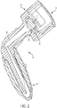
- one example of a system 10 for the closed transfer of fluids includes a connector 12 which provides a leak-proof seal throughout a drug transfer procedure.
- a connector 12 which provides a leak-proof seal throughout a drug transfer procedure.
- Various aspects of the connector 12 are described in U.S. Patent Application Publication No. 2014/0074038 .
- the connector 12 is configured for connecting to an intravenous line (not shown) inserted into a bloodstream of a patient.
- the connector 12 comprises a PhaSealTM connector which is compatible with a Becton Dickinson PhaSealTM System available from Becton, Dickinson and Company of Franklin Lakes, N.J.
- the connector 12 comprises a connector which is compatible with other closed system drug transfer devices.
- the connector 12 has a distal end 14 configured for connecting to an intravenous line, such as by a luer-type fitting.
- a proximal end 16 of the connector 12 is configured for connecting to an injector (not shown), such that drugs from the injector may be delivered to a patient.
- the connector 12 defines a passageway 18 (shown in FIG. 1B ) between the distal end 14 and the proximal end 16.
- the passageway 18 may be substantially linear, such as shown in FIG. 1B .
- the passageway 18 may be L-shaped.
- the passageway 18 and/or an overall shape of the connector 12 may have any other shape.
- the connector 12 further includes a seal arrangement positioned within the passageway 18.
- the seal arrangement includes a membrane 34.
- the membrane 34 extends across the passageway 18 and is retained axially from moving within the passageway 18.
- the membrane 34 includes a body 100 having a proximal portion 102 and a distal portion 104.
- the membrane 34 is retained within a membrane seat 20 between the distal end 14 and the proximal end 16.
- the membrane 34 is retained within the membrane seat 20 by a lip 22 that engages at least a portion of the proximal portion 102 of the membrane 34.
- a needle (not shown) of the injector is configured to extend through the membrane 34 from the proximal end 102 toward the distal end 104 during a drug transfer procedure.
- a distal end of the cannula is configured to pierce the membrane 34 and extend through the membrane 34.
- the membrane 34 is configured to engage and seal an intermediate portion of the cannula to maintain a sealed and leak-free connection between the connector 12 and the injector.
- the membrane 34 has features that are configured to improve the resealing qualities after the penetration of the needle.
- various examples of the membrane 34, discussed herein have features that are configured to minimize coring (generation of particles during cannula penetration).
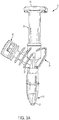
- one example of a system 10 for the closed transfer of fluids includes an infusion adapter 24 configured to securely connect to an intravenous bag in a leak-proof manner for use in a drug transfer procedure.
- an infusion adapter 24 configured to securely connect to an intravenous bag in a leak-proof manner for use in a drug transfer procedure.
- the infusion adapter 24 has a PhaSeal connector which is compatible with a Becton Dickinson PhaSealTM System available from Becton, Dickinson and Company of Franklin Lakes, N.J.
- the infusion adapter 24 comprises a connector which is compatible with other closed system drug transfer devices.
- the infusion adapter 24 includes a connection portion 26 located at a distal end 28, a first port 30 located at a first port end 32, and a second port 35 located at a second port end 36.
- the connection portion 26 includes an anchor component and a fluid channel 40 (shown in FIG. 3B ).
- the first port 30 includes a first port fluid channel 42 and the second port 35 includes a second port fluid channel 44.
- the fluid channel 40 of the connection portion 26 is in fluid communication with the first port fluid channel 42 of the first port 30 such that a fluid may flow into the infusion adapter 24 at the first port 30, travel through the first port fluid channel 42 to the fluid channel 40 of the connection portion 26 and out the distal end 28 of the infusion adapter 24.
- the fluid channel 40 of the connection portion 26 is also in fluid communication with the second port fluid channel 44 of the second port 35 such that a fluid may flow into the infusion adapter 24 at the distal end 28 of the connection portion 26, travel through the fluid channel 40 to the second port fluid channel 44 and out the second port 35 of the infusion adapter 24.
- the infusion adapter 24 may comprise a generally Y-shape. Further, it is contemplated that the infusion adapter 24 may be made available in a variety of shapes and sizes as long as the first port 30 is spaced a distance from the second port 35 so that the first port 30 may be connected to a syringe assembly containing a medication fluid and the second port 35 may be connected to an intravenous line that is adapted for connection to a bloodstream of a patient.
- the infusion adapter 24 may comprise a generally T-shape.
- the infusion adapter 24 further includes a seal arrangement positioned within the first port fluid channel 42.
- the seal arrangement includes the membrane 34, such as the membrane 34 described herein with reference to FIGS. 1A-1B .
- the membrane 34 extends across the first port fluid channel 42 and is retained axially from moving within the first port fluid channel 42.
- the membrane 34 is retained within a membrane seat 20 of the first port fluid channel 42.
- the membrane 34 is retained within the membrane seat 20 by a lip 22 that engages at least a portion of the proximal portion of the membrane 34.
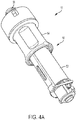
- one example of a system 10 for the closed transfer of fluids includes an injector 50.
- the injector 50 has a tubular body 52, an outer sleeve 54, and an adapter 56.
- the injector 50 is configured to establish fluid communication between a first medical container and a second medical container or between a medical container and a further device, such as a vial adapter.
- Commonly used medical fluid containers include syringes, vials, cartridges, fluid containing bags, medical lines, or similar structures and conduits for holding medical fluids such as drugs, solvents, and diluents.
- the injector 50 is used to establish fluid communication between the containers so that a user may inject fluid from one container to the other or may draw fluid from one container to the other.
- the injector 50 also includes a structure for locking the device to the first and/or second medical containers and to maintain the connection between the connector and container.
- Fluid communication between the medical containers is established by moving the outer sleeve 54 from a first position in which a portion of the tubular body 52 extends from the outer sleeve 54, to a second, engaged position in which the outer sleeve 54 encloses the tubular body 52.
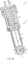
- the tubular body 52 further includes a needle 58 (shown in FIG. 4B ) extending longitudinally through the tubular body 52 from its proximal end to the distal end.
- the needle 58 defines a lumen which provides a fluid path through the tubular body 52.
- the needle 58 is formed from medical grade metal or other material capable of being sharpened to a tip 59 that is capable of piercing the sealing arrangement, such as the membrane 34.
- the needle 58 has a first position in which it is entirely enclosed within the tubular body 52 and a second, exposed position where the needle 58 is forced through the membrane 34 and brought into contact with the second medical container or vial adapter.
- the membrane 34 extends across the inner cavity of the tubular body 52 and is retained axially from moving within the tubular body 52.
- the membrane 34 is retained within a membrane seat 20 of the tubular body 52.
- the membrane 34 is retained within the membrane seat 20 by a lip 22 that engages at least a portion of the proximal portion of the membrane 34.
- the protector 60 includes a body 62 having a first side 64 and a second side 66, a piercing member 68 (shown in FIG. 5B ) extending from the second side 66 of the body 62, and a removable sleeve 70 surrounding the piercing member 68.
- the protector 60 is configured to transfer fluid from a fluid container having a sealing member, such as a vial, a bottle, or a bag.
- the body 62 includes a first connecting portion 72 extending from the first side 64 of the body 62.
- the first connecting portion 72 is configured to attach the protector 60 to a syringe adapter or other suitable device or container to allow removal or insertion of fluid into the fluid container.
- the protector 60 further includes a pressure equalization arrangement 74 that is configured to equalize the pressure within the container during fluid transfer through the use of an expansible chamber 76.
- the piercing member 68 defines a longitudinal vent channel 78 and a vent opening 80 extending from the distal end of the piercing member 68 toward the proximal end of the piercing member 68.
- the vent opening 80 is in fluid communication with the longitudinal vent channel 78.
- the longitudinal vent channel 78 extends through the body 62 of the protector 60 and is in fluid communication with the expansible chamber 76 of the pressure equalization arrangement 74.
- the longitudinal vent channel 78 and the pressure equalization arrangement 74 is utilized to regulate the pressure within the fluid container and contains the medicament and any vapor thereof within the protector 60 and within the fluid container.
- the pressure equalization arrangement 74 may be the balloon or membrane arrangement shown in U.S. Pat. No. 8,523,838 , although other suitable pressure equalization arrangements may be utilized, such as, but not limited to, a filtered vent exit.
- the protector 60 further includes a longitudinal fluid channel 82 extending through the body 62 and in fluid communication with the first connecting portion 72.
- the first connecting portion 72 may include a seal arrangement positioned to seal the interior of the first connecting portion 72, such as the longitudinal fluid channel 82.
- the seal arrangement includes the membrane 34, such as the membrane 34 described herein with reference to FIGS. 1A- 1B.
- the membrane 34 extends across an inner cavity of the first connecting portion 72 and is retained axially from moving within the tubular body 52.
- the membrane 34 is retained within a membrane seat 20 of the tubular body 52.
- the membrane 34 is retained within the membrane seat 20 by a lip 22 that engages at least a portion of the proximal portion 102 of the membrane 34.
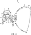
- the lip 22 is folded over the membrane 34 in a radially inward direction after the membrane 34 engages a distal end of the membrane seat 20. In some examples, the lip 22 is folded over the membrane 34 from a first position (shown in FIG. 5C ) to a second position (shown in FIG. 5B ) in a radially inward direction after the membrane 34 engages a distal end of the membrane seat 20. In this manner, the membrane 34 can be retained axially. In addition, at least a portion of an outer perimeter of the membrane 34 may be bonded with at least a portion of an inner perimeter of the membrane seat 20 to radially bond the membrane 34. For example, the membrane 34 may be ultrasonically welded to the membrane seat 20.
- the membrane 34 includes a body 100 having a proximal portion 102 and a distal portion 104.
- the proximal portion 102 and the distal portion 104 are monolithically formed together to define the body 100 as a single, unitary structure.
- the proximal portion 102 and the distal portion 104 may be formed separately and subsequently joined together in a separable or non-separable manner.
- the body 100 is substantially symmetrical about a central axis 106 extending through a central portion of the proximal portion 102 and the distal portion 104.
- the proximal portion 102 and the distal portion 104 may have a substantially circular cross-section across the central axis 106.
- the membrane 34 may be manufactured from an elastomeric material, such as a thermoplastic elastomer material, or isoprene.
- the body 100 may have a skirt 107 extending radially outward from the distal portion 104 such that a lip 108 is formed between the proximal portion 102 and the distal portion 104.
- the lip 108 may be defined by a proximal surface 110 of the distal portion 104.
- the lip 108 defines an engagement surface such that the body 100 of the membrane 34 can engage at least a portion of the system 10, such as at least a portion of the membrane seat 20.
- the lip 108 may be substantially perpendicular relative to the central axis 106.
- the lip 108 may be angled at a non-orthogonal angle relative to the central axis 106.
- the lip 108 may have a planar surface, a non-planar surface, or a combination thereof.
- a proximal surface 112 of the proximal portion 102 may have a dome-shaped or convex surface with its apex aligned with the central axis 106.
- the proximal surface 112 of the proximal portion 102 may have a substantially planar surface or a frusto-conical surface.
- the proximal surface 112 of the proximal portion 102 may have a non-planar surface comprised of one or more linear and/or non-linear sections.
- the outer perimeter of the proximal surface 112 of the proximal portion 102 may have a radiused edge 114 that transitions to a sidewall 116 of the proximal portion 102.
- the sidewall 116 is joined with the proximal surface 110 of the distal portion 104.
- the proximal portion 102 and the distal portion 104 may be aligned coaxially such that the central axis 106 extends through a center of both portions.
- a central axis of the proximal portion 102 may be offset relative to a central axis of the distal portion 104.
- the distal portion 104 may have at least one well 120 recessed in a proximal direction from a distal surface 140 of the distal portion 104.
- the at least one well 120 may be formed as a channel that is recessed into the body of the distal portion 104.
- the at least one well 120 has a first end 122 separated from a second end 124 by a pair of sidewalls 126.
- the first end 122 is open, while the second end 124 is closed.
- the sidewalls 126 are spaced apart from each other by a distance W, which defines a width of the at least one well 120.
- the at least one well 120 may be continuous in a circumferential direction about the central axis 106 at a radius R away from the central axis 106 to define an annular shape.
- the at least one well 120 may have a continuous, non-circular shape, such as an oval shape, rectangular shape, or other polygonal shape.
- a plurality of continuous wells 120 may be provided at different radii away from the central axis 106.
- the at least one well 120 may extend over a portion of a full circumference about the central axis 106 at a radius R away from the central axis 106. In this manner, terminal ends of the well 120 are separated from each other by the body of the distal portion 104 to define an interrupted annular shape.
- the at least one well 120 may have an interrupted, non-circular shape, such as an interrupted oval shape, rectangular shape, or other polygonal shape.
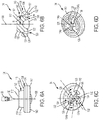
- a plurality of wells 120 may be provided. All of the wells 120 may be provided at a same radius R away from the central axis 106. In some examples, at least one of the plurality of wells 120 may be provided at a radius that is larger or smaller than the radius R of the remaining wells 120. With reference to FIGS. 6C-6D , each of the plurality of wells 120 may extend over an angular extension ⁇ of a full circumference about the central axis 106 to define a length of the well 120. The wells 120 may have an equal or unequal angular extension ⁇ . Each of the plurality of wells 120 may be separated from adjoining wells 120 by a connecting rib 128.
- Each connecting rib 128 may have an equal or unequal angular extent between adjacent wells 120. In other examples, at least one well 120 may have an unequal angular extension ⁇ between adjacent wells 120.
- the connecting ribs 128 bridge the gap between a central portion 130 of the body 100 and an outer portion 132 of the body 100 due to the presence of one or more wells 120. In this manner, dimensional stability of the membrane body 100 is retained after the cannula, such as the needle 58 shown in FIG. 4B , is retracted from the membrane 34.
- the at least one well 120 is configured to reduce compression of the membrane 34 in certain circumstances, such as during ultrasonic welding of the membrane 34 with at least one component of the system 10. Without intending to be bound by theory, it has been found through experimentation that ultrasonic welding of the membrane 34 with the housing 16 may result in a localized compression of the membrane material within the membrane body 100, thereby affecting how easily the needle 58 can penetrate the membrane 34.
- the at least one well 120 isolates the central portion 130 of the body 100 from the outer portion 132 that radially surrounds the central portion 130 by creating a space therebetween. In this manner, any material compression that may occur due to welding of an outer periphery of the membrane 34 will be localized to the outer portion 132 without affecting the central portion 130.
- the needle 58 can freely penetrate the body 100 of the membrane 34.
- the at least one well 120 allows for a radial expansion of the central portion 130 during penetration of the needle 58 without a corresponding expansion of the outer portion 132. In this manner, the at least one well 120 absorbs the deformation of the central portion 130 of the membrane 34 to minimize or eliminate coring during penetration of the needle 58.
- the membrane 34 has at least one slit 134 extending through at least a portion of the body 100.
- the at least one slit 134 extends through at least a portion of the distal portion 104 of the body 100 in a direction along the central axis 106 (shown in FIGS. 6A-6B ).
- the at least one slit 134 extends through the entire distal portion 104 of the body 100 and at least a portion of the proximal portion 102 in a direction along the central axis 106.
- the at least one slit 134 extends through the entire body 100 of the membrane 34 in a direction along the central axis 106.
- the axial extent of the at least one slit 134 in a direction along the central axis 106 reduces the length that the distal end 30 of the needle 58 must penetrate through the body 100 of the membrane 34, thereby reducing or eliminating the possibility of coring (removal of material from the body 100 of the membrane 34).
- the at least one slit 134 is desirably oriented such that the needle 58 penetrates through the slit 134 during insertion of the needle 58 through the membrane 34.
- the needle 58 may partition the at least one slit 134 as the needle 58 is inserted through the membrane 34 by flexing the body 100 of the membrane 34 into an open position. After withdrawing the needle 58 from the membrane 34, the at least one slit 134 is configured to close back to its original position without any deformation of the body 100 of the membrane 34. In this manner, the at least one slit 134 creates a hydraulic seal to prevent passage of liquid or gas through the membrane 34. In some examples, such as shown in FIG.
- the at least one slit 134 may be substantially linear, curved, or a combination thereof, such that the slit 134 bisects the central portion 130 in half at the location of the slit 134.
- the slit 134 may have a rounded shape when viewed in a cross-sectional plane of the membrane 34 along the central axis 106.
- the slit 134 may be positioned on a raised area 142 that protrudes distally from a distal surface 140 of the distal portion 104.
- the raised area 142 may have an arcuate shape with an apex intersecting the central axis 106.
- the shape of the raised area 142 desirably corresponds to the shape of the slit 134.
- the raised area 142 may also be linear along its longitudinal length with an arcuate cross-sectional profile in a plane parallel to the plane of the central axis 106.
- the at least one slit 134 may be substantially cross-shaped with a pair of slits 134a, 134b intersecting at an approximate midpoint thereof.
- the pair of slits 134a, 134b may be oriented at substantially right angles relative to each other, or the pair of slits 134a, 134b may intersect at acute or obtuse angles.
- Each slit 134a, 134b may extend through at least a portion of the distal portion 104 of the body 100 in a direction along the central axis 106.
- Each slit 134a, 134b may be substantially linear, curved, or a combination thereof.
- the slits 134a, 134b are desirably oriented such that the needle 58 penetrates through an intersection point 136 of the pair of slits 134a, 134b during insertion of the needle 58 through the membrane 34.
- the at least one slit 134 may be substantially Y-shaped with three individual slits 134a, 134b, 134c connected to one another at one of their end points.
- the slits 134a, 134b, 134c may be oriented such that the slits 134a, 134b, 134c intersect at equal or unequal angles therebetween.
- Each slit 134a, 134b, 134c may extend through at least a portion of the distal portion 104 of the body 100 in a direction along the central axis 106.
- Each slit 134a, 134b, 134c may be substantially linear, curved, or a combination thereof.
- the slits 134a, 134b, 134c are desirably oriented such that the needle 58 penetrates through an intersection point 136 of the slits 134a, 134b, 134c during insertion of the needle 58 through the membrane 34.
- the membrane 34 may have a retention ring 138 that protrudes distally from a distal surface 140 of the distal portion 104.
- the retention ring 138 is configured to maintain the membrane 34 in its position within the housing 16.
- the retention ring 138 is shaped to engage a corresponding groove (not shown) on the housing 16.
- the retention ring 138 may have a substantially semi-circular shape in cross section taken along a plane extending in a direction of the central axis 106.
- the retention ring 138 may be formed as a continuous ring centered around the central axis 106.
- the retention ring 138 may be discontinuous, such that it does not fully extend around the central axis 106.
- the retention ring 138 may be segmented, such that the retention ring 138 is comprised of two or more disconnected segments.
- the membrane 34 is shown in accordance with various examples.
- the components of the membrane 34 shown in FIGS. 7A-7E are substantially similar to the components of the membrane 34 described herein with reference to FIGS. 6A-6D .
- Reference numerals in FIGS. 7A-7E are used to illustrate identical components of the corresponding reference numerals in FIGS. 6A-6D .
- the membrane 34 generally shown in FIGS. 6A-6D is applicable to the aspect of the present disclosure shown in FIGS. 7A-7E , only the relative differences between the membrane 34 generally shown in FIGS. 6A-6D and the membrane 34 generally shown in FIGS. 7A-7E are discussed hereinafter.
- the membrane 34 in the examples shown in FIGS. 7A-7E has the body 100 with the proximal portion 102 and the distal portion 104 monolithically formed together and symmetrical about the central axis 106.
- the distal portion 104 has a skirt 107 such that a lip 108 is formed between the proximal portion 102 and the distal portion 104 as a substantially planar surface.
- the proximal surface 112 of the proximal portion 102 has a substantially planar surface with the radiused edge 114 that transitions to the sidewall 116 of the proximal portion 102.
- the distal surface 140 of the distal portion 104 is substantially planar ( FIGS. 7B-7D ), or curved ( FIG. 7A ).
- the membrane 34 has at least one slit 134 extending through the body 100 of the membrane 34 in a direction along the central axis 106.
- the distal portion 104 has a well 120 recessed in a proximal direction from a distal surface 140 of the distal portion 104.
- the well 120 has a first end 122 separated from a second end 124 by a pair of sidewalls 126.
- the second end 124 is rounded while the sidewalls 126 are curved such that the width W between the sidewalls 126 changes (i.e., increases or decreases) in a direction from the first end 122 toward the second end 124.
- the second end 124 of the well 120 is angled such that the second end 124 tapers toward the central axis 106 in a distal-to-proximal direction.
- the pair of sidewalls 126 has a first sidewall 126a and a second sidewall 126b , with the first sidewall 126a extending in a direction substantially parallel to a direction of the central axis 106, and the second sidewall 126b extending at an angle relative to the first sidewall 126a such that the second sidewall 126b tapers away from the central axis 106 in a distal-to-proximal direction.
- the central portion 130 of the distal portion 104 can be co-planar with the outer portion 132 ( FIG.
- the well 120 is substantially V-shaped with the second end 124 positioned at a central portion of the membrane 34 and aligned with the central axis 106.
- the sidewalls 126 have a plurality of linear segments.
- the membrane 34 is shown in accordance with additional examples.
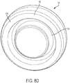
- the distal portion 104 of the membrane 34 may have at least one well 120 recessed in a proximal direction from a distal surface 140 of the distal portion 104.
- the at least one well 120 may be formed as a channel that is recessed into the body of the distal portion 104.
- the at least one well 120 may be continuous in a circumferential direction about the central axis 106 (shown in FIG. 6B ) at a radius R away from the central axis 106 to define an annular shape.
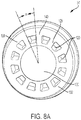
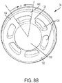
- the at least one well 120 may extend over a portion of a full circumference about the central axis 106 at a radius R away from the central axis 106. In this manner, terminal ends of the well 120 are separated from each other by the body of the distal portion 104 to define an interrupted annular shape. In the examples shown in FIGS.
- each of the plurality of wells 120 may extend over an angular extension ⁇ of a full circumference about the central axis 106 to define a length of the well 120.
- the wells 120 may have an equal or unequal angular extension ⁇ .
- Each of the plurality of wells 120 may be separated from adjoining wells 120 by a connecting rib 128.
- the connecting ribs 128 bridge the gap between a central portion 130 of the body 100 and an outer portion 132 of the body 100 due to the presence of one or more wells 120. In this manner, dimensional stability of the membrane body 100 is retained after the cannula, such as the needle 58 shown in FIG. 4B , is retracted from the membrane 34.
Landscapes
- Health & Medical Sciences (AREA)
- Life Sciences & Earth Sciences (AREA)
- Animal Behavior & Ethology (AREA)
- General Health & Medical Sciences (AREA)
- Public Health (AREA)
- Veterinary Medicine (AREA)
- Pharmacology & Pharmacy (AREA)
- Physics & Mathematics (AREA)
- Fluid Mechanics (AREA)
- Engineering & Computer Science (AREA)
- Vascular Medicine (AREA)
- Anesthesiology (AREA)
- Biomedical Technology (AREA)
- Heart & Thoracic Surgery (AREA)
- Hematology (AREA)
- Infusion, Injection, And Reservoir Apparatuses (AREA)
- Medical Preparation Storing Or Oral Administration Devices (AREA)
- Registering, Tensioning, Guiding Webs, And Rollers Therefor (AREA)
- Sealing Devices (AREA)
- Superconductors And Manufacturing Methods Therefor (AREA)
- Surgical Instruments (AREA)
Claims (17)
- Membran (34) zur Verwendung in Verbindung mit einer Transfervorrichtung mit geschlossenem System, wobei die Membran (34) Folgendes aufweist:einen Körper (100) mit einem proximalen Abschnitt (102) entgegengesetzt zu einem distalen Abschnitt (104) entlang einer Mittelachse (106);eine Schürze (107), die sich radial nach außen von dem distalen Abschnitt (104) erstreckt, so dass eine Lippe (108) an einem Übergang zwischen dem proximalen Abschnitt (102) und dem distalen Abschnitt (104) ausgebildet ist;dadurch gekennzeichnet, dass die Membran (34) ferner Folgendes aufweist:mindestens eine Vertiefung (120), die in dem distalen Abschnitt (104) ausgenommen ist und sich von einem distalen Ende des distalen Abschnitts (104) in eine proximale Richtung erstreckt, wodurch ein Kanal in dem distalen Abschnitt (104) gebildet wird, wobei der Kanal ein offenes erstes Ende (122), ein geschlossenes unteres Ende (124) und ein Paar von Seitenwänden (126) aufweist, die sich zwischen dem ersten Ende (122) und dem zweiten Ende (124) erstrecken; undmindestens einen Schlitz (134), der sich durch mindestens einen Abschnitt des Körpers (100) in eine Richtung einer Ebene erstreckt, die entlang oder parallel zu der Mittelachse (106) ausgerichtet ist.
- Membran (34) nach Anspruch 1, wobei die mindestens eine Vertiefung (120) in einer Umfangsrichtung um die Mittelachse (106) kontinuierlich oder diskontinuierlich ist.
- Membran (34) nach Anspruch 1, wobei die mindestens eine Vertiefung (120) ringförmig ausgebildet ist.
- Membran (34) nach Anspruch 1, wobei die mindestens eine Vertiefung (120) mehrere Vertiefungen (120) aufweist, wobei jede Vertiefung in einem anderen Radius von der Mittelachse (106) entfernt positioniert ist oder in einem gleichen Radius von der Mittelachse (106) entfernt positioniert ist und durch mindestens eine Verbindungsrippe (128) voneinander getrennt ist.
- Membran (34) nach Anspruch 1, wobei sich der mindestens eine Schlitz (134) durch mindestens einen Abschnitt des distalen Abschnitts (104) des Körpers (100) in eine Richtung entlang der Mittelachse (106) erstreckt.
- Membran (34) nach Anspruch 1, wobei der mindestens eine Schlitz (134) derart ausgestaltet ist, dass er durch eine Kanüle (58) während des Eindringens der Kanüle (58) durch die Membran (34) geöffnet wird und beim Herausziehen der Kanüle (58) aus der Membran (34) geschlossen wird.
- Membran (34) nach Anspruch 1, wobei der mindestens eine Schlitz (134) auf einem erhöhten Bereich positioniert ist, der distal von dem distalen Abschnitt (104) des distalen Endes hervorragt, wobei der erhöhte Bereich vorzugsweise bogenförmig ausgebildet ist mit einem Scheitel an der Mittelachse (106) der Membran (34).
- Membran (34) nach Anspruch 1, wobei der mindestens eine Schlitz (134) aus einem Paar von Schlitzen (134a, 134b) besteht, die einander an einem Mittelpunkt jedes Schlitzes schneiden, oder wobei der mindestens eine Schlitz (134) aus drei Schlitzen (134a, 134b, 134c) besteht, die an einem ihrer Endpunkte miteinander verbunden sind.
- Membran (34) nach Anspruch 8, wobei sich die Schlitze in einem senkrechten Winkel schneiden.
- Membran (34) nach Anspruch 1, wobei die Schlitze derart angeordnet sind, dass die Kanüle (58) die Schlitze durch einen Schnittpunkt der Schlitze durchdringt.
- Membran (34) nach Anspruch 1, ferner mit einem Rückhaltering (138), der in eine distale Richtung von dem distalen Abschnitt (104) des distalen Endes hervorragt, wobei der Rückhaltering (138) vorzugsweise ringförmig ausgebildet ist.
- Membran (34) nach Anspruch 11, wobei der Rückhaltering (138) in einer Umfangsrichtung um die Mittelachse (106) kontinuierlich oder diskontinuierlich ist.
- Membran (34) nach Anspruch 1, wobei der proximale Abschnitt (102) und der distale Abschnitt (104) zusammen monolithisch ausgebildet sind.
- Membran (34) nach Anspruch 1, wobei der Körper (100) um die Mittelachse (106) herum symmetrisch ist und/oder wobei die Lippe (108) im Wesentlichen senkrecht zu der Mittelachse (106) ist.
- Membran (34) nach Anspruch 1, wobei ein proximales Ende des proximalen Abschnitts (102) eine konvexe oder planare Oberfläche aufweist.
- Membran (34) nach Anspruch 1, wobei ein distales Ende des distalen Abschnitts (104) eine konvexe oder planare Oberfläche aufweist.
- Membran (34) nach Anspruch 1, wobei ein Außenumfang des proximalen Abschnitts (102) eine gerundete Kante (114) aufweist.
Applications Claiming Priority (2)
| Application Number | Priority Date | Filing Date | Title |
|---|---|---|---|
| US201762445393P | 2017-01-12 | 2017-01-12 | |
| PCT/US2018/013274 WO2018132540A1 (en) | 2017-01-12 | 2018-01-11 | Closed system stress resistant membrane |
Publications (2)
| Publication Number | Publication Date |
|---|---|
| EP3568117A1 EP3568117A1 (de) | 2019-11-20 |
| EP3568117B1 true EP3568117B1 (de) | 2021-03-03 |
Family
ID=61074596
Family Applications (1)
| Application Number | Title | Priority Date | Filing Date |
|---|---|---|---|
| EP18702015.1A Active EP3568117B1 (de) | 2017-01-12 | 2018-01-11 | Belastungsresistente membran für geschlossenes system |
Country Status (10)
| Country | Link |
|---|---|
| US (2) | US12290491B2 (de) |
| EP (1) | EP3568117B1 (de) |
| JP (2) | JP7066723B2 (de) |
| CN (1) | CN110325165B (de) |
| AU (1) | AU2018207411B2 (de) |
| BR (1) | BR112019014384B1 (de) |
| CA (1) | CA3049913A1 (de) |
| ES (1) | ES2857819T3 (de) |
| IL (1) | IL267972B2 (de) |
| WO (1) | WO2018132540A1 (de) |
Families Citing this family (11)
| Publication number | Priority date | Publication date | Assignee | Title |
|---|---|---|---|---|
| US7547300B2 (en) | 2006-04-12 | 2009-06-16 | Icu Medical, Inc. | Vial adaptor for regulating pressure |
| WO2013025946A1 (en) | 2011-08-18 | 2013-02-21 | Icu Medical, Inc. | Pressure-regulating vial adaptors |
| WO2013142618A1 (en) | 2012-03-22 | 2013-09-26 | Icu Medical, Inc. | Pressure-regulating vial adaptors |
| US9089475B2 (en) | 2013-01-23 | 2015-07-28 | Icu Medical, Inc. | Pressure-regulating vial adaptors |
| AU2014290124B2 (en) | 2013-07-19 | 2019-05-09 | Icu Medical, Inc. | Pressure-regulating fluid transfer systems and methods |
| CA2953229C (en) | 2014-06-20 | 2024-01-02 | Icu Medical, Inc. | Pressure-regulating vial adaptors |
| CA3012733C (en) | 2016-01-29 | 2023-09-12 | Icu Medical, Inc. | Pressure-regulating vial adaptors |
| JP7063891B2 (ja) | 2016-09-30 | 2022-05-09 | アイシーユー・メディカル・インコーポレーテッド | バイアルアダプタ |
| EP3672681B1 (de) * | 2017-08-22 | 2024-09-25 | Roche Diabetes Care GmbH | Selbst-dichtendes septum |
| CN115103660A (zh) * | 2020-01-09 | 2022-09-23 | 贝克顿·迪金森公司 | 药物转移装置 |
| JP2023512802A (ja) * | 2020-02-05 | 2023-03-29 | ベクトン・ディキンソン・アンド・カンパニー | 静脈内ラインをプライミングするためのシステムおよび方法 |
Family Cites Families (29)
| Publication number | Priority date | Publication date | Assignee | Title |
|---|---|---|---|---|
| US5242393A (en) * | 1992-06-18 | 1993-09-07 | Becton, Dickinson And Company | Valved blunt cannula injection site |
| US7033339B1 (en) * | 1998-05-29 | 2006-04-25 | Becton Dickinson And Company (Part Interest) | Self sealing luer receiving stopcock |
| DE19500460A1 (de) * | 1995-01-10 | 1996-07-11 | Pohl Gmbh & Co Kg | Anordnung an Infusionsflaschen oder dergleichen |
| US5921264A (en) * | 1997-08-28 | 1999-07-13 | Paradis; Joseph R. | Swabbable needleless valve |
| US6030582A (en) * | 1998-03-06 | 2000-02-29 | Levy; Abner | Self-resealing, puncturable container cap |
| US20110130740A1 (en) * | 1998-03-06 | 2011-06-02 | Abner Levy | Medication Bottle for Use with Oral Syringe |
| BR9910754A (pt) | 1998-05-29 | 2001-07-03 | Lawrence A Lynn | Receptor luer e método para transferência de fluido |
| DE10223560B4 (de) * | 2002-05-27 | 2006-01-19 | Fresenius Kabi Deutschland Gmbh | Konnektor für medizinische Flüssigkeiten enthaltende Verpackungen und Verpackung für medizinische Flüssigkeiten |
| SE526165C2 (sv) * | 2003-04-23 | 2005-07-19 | Hugo Nilsson | Självstängande utmatningsanordning för vätska |
| KR20070086939A (ko) | 2003-07-09 | 2007-08-27 | 가부시키가이샤 제이.에무.에스 | 혼합 주사 포트 |
| MX2009013567A (es) * | 2007-06-12 | 2010-02-17 | Becton Dickinson Co | Conjunto de jeringa incluyendo un mecanismo de prevención de reutilización. |
| US8523838B2 (en) * | 2008-12-15 | 2013-09-03 | Carmel Pharma Ab | Connector device |
| FR2948861B1 (fr) * | 2009-08-07 | 2013-08-30 | Chanel Parfums Beaute | Dispositif de produit cosmetique presentant un orifice de distribution |
| IT1403656B1 (it) * | 2011-01-28 | 2013-10-31 | Frattini Paolo Giuseppe Gobbi | Connettore a chiusura ermetica, perforabile senza ago ed automaticamente richiudibile a tenuta, per tubi flessibili destinati alla raccolta e all'erogazione di soluzioni liquide ad uso farmacologico e/o nutrizionale. |
| EP2554214A1 (de) * | 2011-08-04 | 2013-02-06 | B. Braun Melsungen AG | Nadelfreier Stecker mit einer faltbaren stabilen Membran und zugehöriges Verfahren |
| JP6174576B2 (ja) * | 2012-05-31 | 2017-08-02 | 学校法人近畿大学 | 曝露防止用キャップ |
| US10406344B2 (en) | 2012-09-11 | 2019-09-10 | Becton Dickinson and Company Limited | Adapter cap for drug transfer assembly |
| WO2014046271A1 (ja) * | 2012-09-21 | 2014-03-27 | 二プロ株式会社 | 医療用コネクタとその製造方法 |
| CN107929858B (zh) | 2012-11-30 | 2021-03-12 | 贝克顿迪金森有限公司 | 用于药品输送组件的输注适配器 |
| US9724269B2 (en) | 2012-11-30 | 2017-08-08 | Becton Dickinson and Company Ltd. | Connector for fluid communication |
| US10543150B2 (en) * | 2012-12-28 | 2020-01-28 | Jms Co., Ltd. | Vial shield |
| WO2014145313A2 (en) * | 2013-03-15 | 2014-09-18 | Dr. Py Institute, Llc | Controlled non-classified filling device and method |
| US9919826B2 (en) | 2013-09-23 | 2018-03-20 | Becton Dickinson and Company Ltd. | Piercing member for container access device |
| CN110448461B (zh) * | 2014-04-21 | 2022-07-01 | 贝克顿迪金森有限公司 | 带有断开反馈机构的注射器适配器 |
| CN106470657B (zh) | 2014-04-21 | 2020-03-17 | 贝克顿迪金森有限公司 | 用于封闭式转移流体的系统 |
| JP6824042B2 (ja) * | 2015-01-21 | 2021-02-03 | 株式会社大塚製薬工場 | ポートの製造方法、及び薬液バッグの製造方法 |
| CA2975046C (en) * | 2015-01-30 | 2023-09-19 | Becton, Dickinson And Company | Pen needle hub with a patient contact surface |
| MY188947A (en) * | 2015-03-23 | 2022-01-14 | Jms Co Ltd | Adapter |
| CA3002966A1 (en) * | 2015-09-15 | 2017-03-23 | Dr. Py Institute Llc | Septum that decontaminates by interaction with penetrating element |
-
2018
- 2018-01-11 EP EP18702015.1A patent/EP3568117B1/de active Active
- 2018-01-11 US US15/868,123 patent/US12290491B2/en active Active
- 2018-01-11 ES ES18702015T patent/ES2857819T3/es active Active
- 2018-01-11 AU AU2018207411A patent/AU2018207411B2/en active Active
- 2018-01-11 BR BR112019014384-0A patent/BR112019014384B1/pt active IP Right Grant
- 2018-01-11 CN CN201880013258.1A patent/CN110325165B/zh active Active
- 2018-01-11 WO PCT/US2018/013274 patent/WO2018132540A1/en not_active Ceased
- 2018-01-11 IL IL267972A patent/IL267972B2/en unknown
- 2018-01-11 JP JP2019538121A patent/JP7066723B2/ja active Active
- 2018-01-11 CA CA3049913A patent/CA3049913A1/en active Pending
-
2022
- 2022-04-27 JP JP2022073280A patent/JP7258202B2/ja active Active
-
2025
- 2025-04-01 US US19/097,113 patent/US20250228743A1/en active Pending
Non-Patent Citations (1)
| Title |
|---|
| None * |
Also Published As
| Publication number | Publication date |
|---|---|
| JP2020503971A (ja) | 2020-02-06 |
| US20180193227A1 (en) | 2018-07-12 |
| US20250228743A1 (en) | 2025-07-17 |
| BR112019014384B1 (pt) | 2023-04-11 |
| WO2018132540A1 (en) | 2018-07-19 |
| IL267972B1 (en) | 2023-06-01 |
| EP3568117A1 (de) | 2019-11-20 |
| ES2857819T3 (es) | 2021-09-29 |
| AU2018207411A1 (en) | 2019-08-01 |
| CA3049913A1 (en) | 2018-07-19 |
| JP7066723B2 (ja) | 2022-05-13 |
| BR112019014384A2 (pt) | 2020-02-11 |
| US12290491B2 (en) | 2025-05-06 |
| IL267972B2 (en) | 2023-10-01 |
| CN110325165B (zh) | 2022-05-17 |
| IL267972A (en) | 2019-09-26 |
| JP7258202B2 (ja) | 2023-04-14 |
| AU2018207411B2 (en) | 2023-04-13 |
| JP2022097585A (ja) | 2022-06-30 |
| CN110325165A (zh) | 2019-10-11 |
Similar Documents
| Publication | Publication Date | Title |
|---|---|---|
| US20250228743A1 (en) | Closed System Stress Resistant Membrane | |
| US12514977B2 (en) | Infusion adapter | |
| US11154457B2 (en) | Fluid transfer device and packaging therefor | |
| JP6189951B2 (ja) | 均圧化を有する医療用バイアルアクセス器具、および、閉鎖式薬物移送システム | |
| JP7807422B2 (ja) | 吸引アセンブリ付きシリンジアダプタ | |
| EP0930056A2 (de) | Universelles Verbindungsstück | |
| CN111867546B (zh) | 用于流体的密闭式系统转移的连接布置 | |
| US10888496B2 (en) | Medicament vial assembly | |
| CN108289787A (zh) | 具有装配小瓶保留弹性部件的液体药物转移装置 |
Legal Events
| Date | Code | Title | Description |
|---|---|---|---|
| STAA | Information on the status of an ep patent application or granted ep patent |
Free format text: STATUS: UNKNOWN |
|
| STAA | Information on the status of an ep patent application or granted ep patent |
Free format text: STATUS: THE INTERNATIONAL PUBLICATION HAS BEEN MADE |
|
| PUAI | Public reference made under article 153(3) epc to a published international application that has entered the european phase |
Free format text: ORIGINAL CODE: 0009012 |
|
| STAA | Information on the status of an ep patent application or granted ep patent |
Free format text: STATUS: REQUEST FOR EXAMINATION WAS MADE |
|
| 17P | Request for examination filed |
Effective date: 20190812 |
|
| AK | Designated contracting states |
Kind code of ref document: A1 Designated state(s): AL AT BE BG CH CY CZ DE DK EE ES FI FR GB GR HR HU IE IS IT LI LT LU LV MC MK MT NL NO PL PT RO RS SE SI SK SM TR |
|
| AX | Request for extension of the european patent |
Extension state: BA ME |
|
| DAV | Request for validation of the european patent (deleted) | ||
| DAX | Request for extension of the european patent (deleted) | ||
| GRAP | Despatch of communication of intention to grant a patent |
Free format text: ORIGINAL CODE: EPIDOSNIGR1 |
|
| STAA | Information on the status of an ep patent application or granted ep patent |
Free format text: STATUS: GRANT OF PATENT IS INTENDED |
|
| INTG | Intention to grant announced |
Effective date: 20200811 |
|
| GRAS | Grant fee paid |
Free format text: ORIGINAL CODE: EPIDOSNIGR3 |
|
| GRAA | (expected) grant |
Free format text: ORIGINAL CODE: 0009210 |
|
| STAA | Information on the status of an ep patent application or granted ep patent |
Free format text: STATUS: THE PATENT HAS BEEN GRANTED |
|
| AK | Designated contracting states |
Kind code of ref document: B1 Designated state(s): AL AT BE BG CH CY CZ DE DK EE ES FI FR GB GR HR HU IE IS IT LI LT LU LV MC MK MT NL NO PL PT RO RS SE SI SK SM TR |
|
| REG | Reference to a national code |
Ref country code: GB Ref legal event code: FG4D |
|
| REG | Reference to a national code |
Ref country code: AT Ref legal event code: REF Ref document number: 1366413 Country of ref document: AT Kind code of ref document: T Effective date: 20210315 Ref country code: CH Ref legal event code: EP |
|
| REG | Reference to a national code |
Ref country code: DE Ref legal event code: R096 Ref document number: 602018013361 Country of ref document: DE |
|
| REG | Reference to a national code |
Ref country code: IE Ref legal event code: FG4D |
|
| REG | Reference to a national code |
Ref country code: LT Ref legal event code: MG9D |
|
| PG25 | Lapsed in a contracting state [announced via postgrant information from national office to epo] |
Ref country code: BG Free format text: LAPSE BECAUSE OF FAILURE TO SUBMIT A TRANSLATION OF THE DESCRIPTION OR TO PAY THE FEE WITHIN THE PRESCRIBED TIME-LIMIT Effective date: 20210603 Ref country code: GR Free format text: LAPSE BECAUSE OF FAILURE TO SUBMIT A TRANSLATION OF THE DESCRIPTION OR TO PAY THE FEE WITHIN THE PRESCRIBED TIME-LIMIT Effective date: 20210604 Ref country code: FI Free format text: LAPSE BECAUSE OF FAILURE TO SUBMIT A TRANSLATION OF THE DESCRIPTION OR TO PAY THE FEE WITHIN THE PRESCRIBED TIME-LIMIT Effective date: 20210303 Ref country code: HR Free format text: LAPSE BECAUSE OF FAILURE TO SUBMIT A TRANSLATION OF THE DESCRIPTION OR TO PAY THE FEE WITHIN THE PRESCRIBED TIME-LIMIT Effective date: 20210303 Ref country code: LT Free format text: LAPSE BECAUSE OF FAILURE TO SUBMIT A TRANSLATION OF THE DESCRIPTION OR TO PAY THE FEE WITHIN THE PRESCRIBED TIME-LIMIT Effective date: 20210303 Ref country code: NO Free format text: LAPSE BECAUSE OF FAILURE TO SUBMIT A TRANSLATION OF THE DESCRIPTION OR TO PAY THE FEE WITHIN THE PRESCRIBED TIME-LIMIT Effective date: 20210603 |
|
| REG | Reference to a national code |
Ref country code: NL Ref legal event code: MP Effective date: 20210303 |
|
| REG | Reference to a national code |
Ref country code: AT Ref legal event code: MK05 Ref document number: 1366413 Country of ref document: AT Kind code of ref document: T Effective date: 20210303 |
|
| PG25 | Lapsed in a contracting state [announced via postgrant information from national office to epo] |
Ref country code: SE Free format text: LAPSE BECAUSE OF FAILURE TO SUBMIT A TRANSLATION OF THE DESCRIPTION OR TO PAY THE FEE WITHIN THE PRESCRIBED TIME-LIMIT Effective date: 20210303 Ref country code: PL Free format text: LAPSE BECAUSE OF FAILURE TO SUBMIT A TRANSLATION OF THE DESCRIPTION OR TO PAY THE FEE WITHIN THE PRESCRIBED TIME-LIMIT Effective date: 20210303 Ref country code: RS Free format text: LAPSE BECAUSE OF FAILURE TO SUBMIT A TRANSLATION OF THE DESCRIPTION OR TO PAY THE FEE WITHIN THE PRESCRIBED TIME-LIMIT Effective date: 20210303 Ref country code: LV Free format text: LAPSE BECAUSE OF FAILURE TO SUBMIT A TRANSLATION OF THE DESCRIPTION OR TO PAY THE FEE WITHIN THE PRESCRIBED TIME-LIMIT Effective date: 20210303 |
|
| REG | Reference to a national code |
Ref country code: ES Ref legal event code: FG2A Ref document number: 2857819 Country of ref document: ES Kind code of ref document: T3 Effective date: 20210929 |
|
| PG25 | Lapsed in a contracting state [announced via postgrant information from national office to epo] |
Ref country code: NL Free format text: LAPSE BECAUSE OF FAILURE TO SUBMIT A TRANSLATION OF THE DESCRIPTION OR TO PAY THE FEE WITHIN THE PRESCRIBED TIME-LIMIT Effective date: 20210303 |
|
| PG25 | Lapsed in a contracting state [announced via postgrant information from national office to epo] |
Ref country code: EE Free format text: LAPSE BECAUSE OF FAILURE TO SUBMIT A TRANSLATION OF THE DESCRIPTION OR TO PAY THE FEE WITHIN THE PRESCRIBED TIME-LIMIT Effective date: 20210303 Ref country code: CZ Free format text: LAPSE BECAUSE OF FAILURE TO SUBMIT A TRANSLATION OF THE DESCRIPTION OR TO PAY THE FEE WITHIN THE PRESCRIBED TIME-LIMIT Effective date: 20210303 Ref country code: SM Free format text: LAPSE BECAUSE OF FAILURE TO SUBMIT A TRANSLATION OF THE DESCRIPTION OR TO PAY THE FEE WITHIN THE PRESCRIBED TIME-LIMIT Effective date: 20210303 Ref country code: AT Free format text: LAPSE BECAUSE OF FAILURE TO SUBMIT A TRANSLATION OF THE DESCRIPTION OR TO PAY THE FEE WITHIN THE PRESCRIBED TIME-LIMIT Effective date: 20210303 |
|
| PG25 | Lapsed in a contracting state [announced via postgrant information from national office to epo] |
Ref country code: IS Free format text: LAPSE BECAUSE OF FAILURE TO SUBMIT A TRANSLATION OF THE DESCRIPTION OR TO PAY THE FEE WITHIN THE PRESCRIBED TIME-LIMIT Effective date: 20210703 Ref country code: PT Free format text: LAPSE BECAUSE OF FAILURE TO SUBMIT A TRANSLATION OF THE DESCRIPTION OR TO PAY THE FEE WITHIN THE PRESCRIBED TIME-LIMIT Effective date: 20210705 Ref country code: SK Free format text: LAPSE BECAUSE OF FAILURE TO SUBMIT A TRANSLATION OF THE DESCRIPTION OR TO PAY THE FEE WITHIN THE PRESCRIBED TIME-LIMIT Effective date: 20210303 Ref country code: RO Free format text: LAPSE BECAUSE OF FAILURE TO SUBMIT A TRANSLATION OF THE DESCRIPTION OR TO PAY THE FEE WITHIN THE PRESCRIBED TIME-LIMIT Effective date: 20210303 |
|
| REG | Reference to a national code |
Ref country code: DE Ref legal event code: R097 Ref document number: 602018013361 Country of ref document: DE |
|
| PLBE | No opposition filed within time limit |
Free format text: ORIGINAL CODE: 0009261 |
|
| STAA | Information on the status of an ep patent application or granted ep patent |
Free format text: STATUS: NO OPPOSITION FILED WITHIN TIME LIMIT |
|
| PG25 | Lapsed in a contracting state [announced via postgrant information from national office to epo] |
Ref country code: AL Free format text: LAPSE BECAUSE OF FAILURE TO SUBMIT A TRANSLATION OF THE DESCRIPTION OR TO PAY THE FEE WITHIN THE PRESCRIBED TIME-LIMIT Effective date: 20210303 Ref country code: DK Free format text: LAPSE BECAUSE OF FAILURE TO SUBMIT A TRANSLATION OF THE DESCRIPTION OR TO PAY THE FEE WITHIN THE PRESCRIBED TIME-LIMIT Effective date: 20210303 |
|
| 26N | No opposition filed |
Effective date: 20211206 |
|
| PG25 | Lapsed in a contracting state [announced via postgrant information from national office to epo] |
Ref country code: SI Free format text: LAPSE BECAUSE OF FAILURE TO SUBMIT A TRANSLATION OF THE DESCRIPTION OR TO PAY THE FEE WITHIN THE PRESCRIBED TIME-LIMIT Effective date: 20210303 |
|
| PG25 | Lapsed in a contracting state [announced via postgrant information from national office to epo] |
Ref country code: IS Free format text: LAPSE BECAUSE OF FAILURE TO SUBMIT A TRANSLATION OF THE DESCRIPTION OR TO PAY THE FEE WITHIN THE PRESCRIBED TIME-LIMIT Effective date: 20210703 |
|
| PG25 | Lapsed in a contracting state [announced via postgrant information from national office to epo] |
Ref country code: MC Free format text: LAPSE BECAUSE OF FAILURE TO SUBMIT A TRANSLATION OF THE DESCRIPTION OR TO PAY THE FEE WITHIN THE PRESCRIBED TIME-LIMIT Effective date: 20210303 |
|
| REG | Reference to a national code |
Ref country code: CH Ref legal event code: PL |
|
| REG | Reference to a national code |
Ref country code: BE Ref legal event code: MM Effective date: 20220131 |
|
| PG25 | Lapsed in a contracting state [announced via postgrant information from national office to epo] |
Ref country code: LU Free format text: LAPSE BECAUSE OF NON-PAYMENT OF DUE FEES Effective date: 20220111 |
|
| PG25 | Lapsed in a contracting state [announced via postgrant information from national office to epo] |
Ref country code: BE Free format text: LAPSE BECAUSE OF NON-PAYMENT OF DUE FEES Effective date: 20220131 |
|
| PG25 | Lapsed in a contracting state [announced via postgrant information from national office to epo] |
Ref country code: LI Free format text: LAPSE BECAUSE OF NON-PAYMENT OF DUE FEES Effective date: 20220131 Ref country code: CH Free format text: LAPSE BECAUSE OF NON-PAYMENT OF DUE FEES Effective date: 20220131 |
|
| PG25 | Lapsed in a contracting state [announced via postgrant information from national office to epo] |
Ref country code: IE Free format text: LAPSE BECAUSE OF NON-PAYMENT OF DUE FEES Effective date: 20220111 |
|
| PG25 | Lapsed in a contracting state [announced via postgrant information from national office to epo] |
Ref country code: MK Free format text: LAPSE BECAUSE OF FAILURE TO SUBMIT A TRANSLATION OF THE DESCRIPTION OR TO PAY THE FEE WITHIN THE PRESCRIBED TIME-LIMIT Effective date: 20210303 Ref country code: CY Free format text: LAPSE BECAUSE OF FAILURE TO SUBMIT A TRANSLATION OF THE DESCRIPTION OR TO PAY THE FEE WITHIN THE PRESCRIBED TIME-LIMIT Effective date: 20210303 |
|
| PG25 | Lapsed in a contracting state [announced via postgrant information from national office to epo] |
Ref country code: HU Free format text: LAPSE BECAUSE OF FAILURE TO SUBMIT A TRANSLATION OF THE DESCRIPTION OR TO PAY THE FEE WITHIN THE PRESCRIBED TIME-LIMIT; INVALID AB INITIO Effective date: 20180111 |
|
| PG25 | Lapsed in a contracting state [announced via postgrant information from national office to epo] |
Ref country code: MT Free format text: LAPSE BECAUSE OF FAILURE TO SUBMIT A TRANSLATION OF THE DESCRIPTION OR TO PAY THE FEE WITHIN THE PRESCRIBED TIME-LIMIT Effective date: 20210303 |
|
| PG25 | Lapsed in a contracting state [announced via postgrant information from national office to epo] |
Ref country code: TR Free format text: LAPSE BECAUSE OF FAILURE TO SUBMIT A TRANSLATION OF THE DESCRIPTION OR TO PAY THE FEE WITHIN THE PRESCRIBED TIME-LIMIT Effective date: 20210303 |
|
| PGFP | Annual fee paid to national office [announced via postgrant information from national office to epo] |
Ref country code: GB Payment date: 20251219 Year of fee payment: 9 |
|
| PGFP | Annual fee paid to national office [announced via postgrant information from national office to epo] |
Ref country code: FR Payment date: 20251218 Year of fee payment: 9 |
|
| PGFP | Annual fee paid to national office [announced via postgrant information from national office to epo] |
Ref country code: ES Payment date: 20260202 Year of fee payment: 9 |
|
| PGFP | Annual fee paid to national office [announced via postgrant information from national office to epo] |
Ref country code: DE Payment date: 20251217 Year of fee payment: 9 |
|
| PGFP | Annual fee paid to national office [announced via postgrant information from national office to epo] |
Ref country code: IT Payment date: 20260107 Year of fee payment: 9 |