EP3568239B1 - Presse à cartouche - Google Patents
Presse à cartouche Download PDFInfo
- Publication number
- EP3568239B1 EP3568239B1 EP18700876.8A EP18700876A EP3568239B1 EP 3568239 B1 EP3568239 B1 EP 3568239B1 EP 18700876 A EP18700876 A EP 18700876A EP 3568239 B1 EP3568239 B1 EP 3568239B1
- Authority
- EP
- European Patent Office
- Prior art keywords
- latching
- locking
- push
- push rod
- press according
- Prior art date
- Legal status (The legal status is an assumption and is not a legal conclusion. Google has not performed a legal analysis and makes no representation as to the accuracy of the status listed.)
- Active
Links
Images


Classifications
-
- B—PERFORMING OPERATIONS; TRANSPORTING
- B05—SPRAYING OR ATOMISING IN GENERAL; APPLYING FLUENT MATERIALS TO SURFACES, IN GENERAL
- B05C—APPARATUS FOR APPLYING FLUENT MATERIALS TO SURFACES, IN GENERAL
- B05C17/00—Hand tools or apparatus using hand held tools, for applying liquids or other fluent materials to, for spreading applied liquids or other fluent materials on, or for partially removing applied liquids or other fluent materials from, surfaces
- B05C17/005—Hand tools or apparatus using hand held tools, for applying liquids or other fluent materials to, for spreading applied liquids or other fluent materials on, or for partially removing applied liquids or other fluent materials from, surfaces for discharging material from a reservoir or container located in or on the hand tool through an outlet orifice by pressure without using surface contacting members like pads or brushes
- B05C17/01—Hand tools or apparatus using hand held tools, for applying liquids or other fluent materials to, for spreading applied liquids or other fluent materials on, or for partially removing applied liquids or other fluent materials from, surfaces for discharging material from a reservoir or container located in or on the hand tool through an outlet orifice by pressure without using surface contacting members like pads or brushes with manually mechanically or electrically actuated piston or the like
- B05C17/0116—Hand tools or apparatus using hand held tools, for applying liquids or other fluent materials to, for spreading applied liquids or other fluent materials on, or for partially removing applied liquids or other fluent materials from, surfaces for discharging material from a reservoir or container located in or on the hand tool through an outlet orifice by pressure without using surface contacting members like pads or brushes with manually mechanically or electrically actuated piston or the like characterised by the piston driving means
- B05C17/012—Stepwise advancing mechanism, e.g. pawl and ratchets
- B05C17/0123—Lever actuated
- B05C17/0126—Lever actuated comprising an element, e.g. an arc compensating element, articulated at one end on the lever and at the other end on the piston rod driving means, e.g. a pawl
-
- B—PERFORMING OPERATIONS; TRANSPORTING
- B05—SPRAYING OR ATOMISING IN GENERAL; APPLYING FLUENT MATERIALS TO SURFACES, IN GENERAL
- B05C—APPARATUS FOR APPLYING FLUENT MATERIALS TO SURFACES, IN GENERAL
- B05C17/00—Hand tools or apparatus using hand held tools, for applying liquids or other fluent materials to, for spreading applied liquids or other fluent materials on, or for partially removing applied liquids or other fluent materials from, surfaces
- B05C17/005—Hand tools or apparatus using hand held tools, for applying liquids or other fluent materials to, for spreading applied liquids or other fluent materials on, or for partially removing applied liquids or other fluent materials from, surfaces for discharging material from a reservoir or container located in or on the hand tool through an outlet orifice by pressure without using surface contacting members like pads or brushes
- B05C17/00576—Hand tools or apparatus using hand held tools, for applying liquids or other fluent materials to, for spreading applied liquids or other fluent materials on, or for partially removing applied liquids or other fluent materials from, surfaces for discharging material from a reservoir or container located in or on the hand tool through an outlet orifice by pressure without using surface contacting members like pads or brushes characterised by the construction of a piston as pressure exerting means, or of the co-operating container
-
- B—PERFORMING OPERATIONS; TRANSPORTING
- B05—SPRAYING OR ATOMISING IN GENERAL; APPLYING FLUENT MATERIALS TO SURFACES, IN GENERAL
- B05C—APPARATUS FOR APPLYING FLUENT MATERIALS TO SURFACES, IN GENERAL
- B05C17/00—Hand tools or apparatus using hand held tools, for applying liquids or other fluent materials to, for spreading applied liquids or other fluent materials on, or for partially removing applied liquids or other fluent materials from, surfaces
- B05C17/005—Hand tools or apparatus using hand held tools, for applying liquids or other fluent materials to, for spreading applied liquids or other fluent materials on, or for partially removing applied liquids or other fluent materials from, surfaces for discharging material from a reservoir or container located in or on the hand tool through an outlet orifice by pressure without using surface contacting members like pads or brushes
- B05C17/01—Hand tools or apparatus using hand held tools, for applying liquids or other fluent materials to, for spreading applied liquids or other fluent materials on, or for partially removing applied liquids or other fluent materials from, surfaces for discharging material from a reservoir or container located in or on the hand tool through an outlet orifice by pressure without using surface contacting members like pads or brushes with manually mechanically or electrically actuated piston or the like
- B05C17/014—Hand tools or apparatus using hand held tools, for applying liquids or other fluent materials to, for spreading applied liquids or other fluent materials on, or for partially removing applied liquids or other fluent materials from, surfaces for discharging material from a reservoir or container located in or on the hand tool through an outlet orifice by pressure without using surface contacting members like pads or brushes with manually mechanically or electrically actuated piston or the like comprising means for preventing oozing
-
- B—PERFORMING OPERATIONS; TRANSPORTING
- B05—SPRAYING OR ATOMISING IN GENERAL; APPLYING FLUENT MATERIALS TO SURFACES, IN GENERAL
- B05C—APPARATUS FOR APPLYING FLUENT MATERIALS TO SURFACES, IN GENERAL
- B05C17/00—Hand tools or apparatus using hand held tools, for applying liquids or other fluent materials to, for spreading applied liquids or other fluent materials on, or for partially removing applied liquids or other fluent materials from, surfaces
- B05C17/005—Hand tools or apparatus using hand held tools, for applying liquids or other fluent materials to, for spreading applied liquids or other fluent materials on, or for partially removing applied liquids or other fluent materials from, surfaces for discharging material from a reservoir or container located in or on the hand tool through an outlet orifice by pressure without using surface contacting members like pads or brushes
- B05C17/00583—Hand tools or apparatus using hand held tools, for applying liquids or other fluent materials to, for spreading applied liquids or other fluent materials on, or for partially removing applied liquids or other fluent materials from, surfaces for discharging material from a reservoir or container located in or on the hand tool through an outlet orifice by pressure without using surface contacting members like pads or brushes the container for the material to be dispensed being deformable
Definitions
- the invention relates to a cartridge press with an actuating housing which has a handle, the movement of which relative to the actuating housing in an actuating direction results in a displacement of a pressure rod displaceably mounted in the actuating housing in a pressure direction, and with a receiving device for receiving a pasty mass which can be pressed out of a hose or a cartridge by the displacement of the pressure rod, wherein the receiving device is rotatably fastened to the actuating housing, for which purpose a fastening base having an opening for the passage of the pressure rod projects into a fastening opening and is there tied axially relative to the pressure rod with a form-fitting fastening means.
- the invention further relates to a cartridge press with an actuating housing which has a handle, the movement of which relative to the actuating housing in an actuating direction results in a displacement of a pressure rod in a pressure direction, with a receiving device for receiving a pasty mass which can be pressed out of a hose or a cartridge by the displacement of the pressure rod and with a release lever arranged on a first side of the pressure rod on the actuating housing for interacting with a push-back locking element, and with a changeover switch which can be brought from a first switching position, in which the push-back locking element assumes an operative position relative to the pressure rod, into a second switching position, in which the push-back locking element assumes an inoperative position relative to the pressure rod.
- a cartridge press of the generic type relating to a first aspect of the invention describes the US 5,887,765 .
- the cartridge press has an actuating housing with a handle which is pivotably attached to the actuating housing and can be pivoted relative to a handle.
- the handle engages a driving member which clamps itself onto a push rod so that the push rod can be gradually moved in a pressure direction.
- a threaded piece with an opening for the push rod to pass through is screwed with its external thread into an internal thread of the actuating housing in order to form-fit a receiving device in the form of a tray for receiving a cartridge to the actuating housing.
- the receiving device can hold a cartridge with a pasty mass which is squeezed out by moving the push rod.
- the US 5,431, 654 describes a cartridge ejection device in which the actuating housing has an arcuate groove into which a radially outwardly projecting collar of the receiving device can be inserted in order to thereby connect the receiving device to the actuating housing in a form-fitting and rotatable manner.
- a cartridge press is already known in which a mounting base is located on the actuator housing, onto which a connection profile in the form of an arcuate ring groove and a receiving device can be pushed in the radial direction.
- the pressure rod secures the fastening of the receiving device to the actuator housing.
- the DE 10 2014 116 514 describes a cartridge press of a second aspect of the invention, in which a changeover switch is provided with which a push-back locking member can be brought between an active position and an inactive position.
- the DE 10 2014 105 935 A1 describes a cartridge press in which the angle between the handle and a handgrip can be adjusted. This is done with an adjustable eccentric bushing.
- EP 2 878 383 A1 and US 2012/118913 other cartridge presses are described.
- the invention is based on the object of specifying measures by means of which a cartridge press is further developed in a manner that is advantageous in use.
- the form-locking means with which the receiving device is tied to the actuating housing is further developed.
- a fastening base engages in a fastening opening.
- the fastening opening opens into a radial shaft which extends in the radial direction relative to the direction of extension of the push rod.
- a locking slider which has a locking flank can be inserted into the radial shaft. In a form-locking position, the locking flank engages in an annular groove of the fastening base.
- the fastening base is rotatable in the fastening opening so that the receiving device can be rotated about the axis formed by the push rod.
- the fastening base is preferably formed by the receiving device and is in particular connected to an end piece of the receiving device using the same material.
- the radial shaft has two walls that run parallel to one another, the distance between which preferably corresponds to the material thickness of the restraining slide. Both walls of the radial shaft can have an opening. The two openings can be aligned with one another.
- the fastening base can be inserted into both openings.
- the annular groove then extends in the area of the radial shaft.
- the radial shaft is preferably formed by the actuating housing and has an opening that points to a first side of the actuating housing. The handle or a release lever is arranged on this first side.
- the release lever can extend in front of the opening of the radial shaft so that the restraining slide can only be pushed into the radial shaft when the release lever is pivoted back.
- the restraining flank of the restraining slide is preferably formed by the edge of a U-shaped cut in the restraining slide, which is preferably made of steel, die-cast or a similar material.
- the fastening base is subjected to spring force in the axial direction of the push rod by a spring. When the fastening base is inserted into the fastening opening, this compression spring must be tensioned.
- the compression spring can be a compression spring associated with a push-back locking element, which is supported on an end face of the fastening base and through which the push rod passes.
- One end of the spring can be arranged in a depression in the end face of the fastening base.
- the other end can be supported on the push-back locking element formed by a steel plate.
- An end cap forming the end piece, from which the fastening base preferably originates, can form an end wall which rests in contact with an end wall of the actuating housing.
- the receiving device can have a receiving body which is designed as a tube or as a trough.
- a pressure plate attached to the end of the push rod can be moved in the tube or the trough, with which a hose containing the pasty mass or a piston of a cartridge can be moved in such a way that is that the pasty mass is pressed out through an opening of a head piece, which is opposite the end piece. This is preferably done by a nozzle.
- the two opposite openings of a tubular receiving body are preferably closed by the end piece or head piece.
- the head piece and the end piece are connected to the receiving body by means of a form-fitting means. This can be a bayonet closure or a thread.
- a second aspect of the invention relates to a further development of a changeover switch which can be moved from a first switching position, in which a push-back locking element assumes an active position on the push rod, to a second switching position, in which the push-back locking element assumes an inactive position relative to the push rod.
- the push rod can be moved in the direction of pressure by gradually operating the handle.
- the push-back locking element prevents the push rod from being moved backwards. Only when the push-back locking element is moved by pivoting a release lever can the push rod be moved against the direction of pressure.
- the inactive position the push rod can also be moved back without operating the release lever.
- the inactive position is particularly advantageous in use when the pasty mass is compressed when it is squeezed out and the compression of the pasty mass can lead to dripping. In the inactive position, the pasty mass can relax again after the handle has been operated.
- the changeover switch is located on the opposite side of the release lever relative to the push rod.
- the release lever can have an extension which acts on the push-back locking element, which is preferably formed by a plate, on a first side.
- a section of the changeover switch engages the push-back locking member.
- the section is an extension or an eccentric section and forms a projection that projects radially from the pivot axis of the changeover switch.
- the section preferably rests on the push-back locking member in the active position.
- the push-back locking member preferably has two broad side surfaces facing away from one another. One of the two broad side surfaces faces in the direction of pressure.
- the section of the changeover switch and the eccentric projection of the release lever engage the broad side surface facing away from it, the push-back locking member being supported on the release lever and on the changeover switch by the force of a spring and extending essentially in a plane transverse to the axis of the push rod.
- a handle width adjustment is also provided.
- an eccentric sleeve is mounted on a pivot axis around which the handle can be pivoted.
- the eccentric sleeve can be rotated using a changeover lever in order to change the angle between the handle and the handle.
- the handle has a drive arm which projects into the actuating housing and which engages at least one driving element which can assume a driving position relative to the push rod in order to gradually move the push rod in the direction of pressure by pivoting the handle.
- a return spring is provided which moves the driving element back to its original position.
- the receiving device preferably consists of a receiving body, which in particular has the shape of a tube that is open on both sides.
- One end of the receiving body is inserted into a receiving opening of an end piece.
- the end piece has a sleeve section into which a first end of the receiving body is inserted.
- An axial binding of the receiving body to the end piece is provided.
- a second end of the receiving body is inserted into a receiving opening of a head piece, which has an opening for the pasty mass to pass through.
- the opening can in particular accommodate a nozzle.
- the head piece has a sleeve section into which the end of the receiving body is inserted.
- the sleeve section of the end piece and the sleeve section of the head piece are each detachably connected to the receiving body via a bayonet-like connection.
- the head piece or the end piece In order to axially bind the head piece or the end piece to the receiving body, the head piece or the end piece must be rotated by an angle of rotation after the end of the receiving body has been inserted into the sleeve section, so that the binding means for axial binding follow one another in the axial direction.
- locking means are provided.
- locking projections are provided which interact with counter-locking projections.
- the counter-locking projections preferably form locking recesses into which the locking projections can engage.
- the locking projections can be formed by the receiving body and the counter-locking projections or locking recesses can be formed by the sleeve sections.
- the locking means form locking beads which engage in locking grooves, with the receiving body preferably forming radially outward-pointing locking beads and the sleeve sections forming radially inward-pointing locking grooves.
- a torque must be applied to the sleeve section.
- the two locking connections are designed in such a way that a lower torque must be applied to release the head piece from the receiving body than to release the receiving body from the end piece.
- the locking connection between the end piece and the receiving body a larger number of locking beads engage in locking recesses than in the locking connection between the head piece and the receiving body.
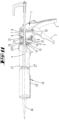
- the cartridge presses shown in the drawings have an actuating housing 1, which is made of plastic or another material, such as metal, and on which a Handle 2 in the direction of a handle 3 is also pivotally connected to a release lever 5.
- a pressure rod 4 is mounted in the actuating housing 1 so that it can move in the direction of its axis.
- a handle and a stop spring are located on the rear end of the pressure rod 4.
- a pressure plate 27 is attached to the pressure-side end of the pressure rod 4.
- the end of the pressure rod 4 can have a circumferential groove in which a locking ring is inserted.
- a thread of the pressure rod 4 engages in a thread of the pressure plate 27.
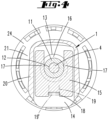
- the edge 27' of the pressure plate 27 engages in a curved groove 36 of a pressure stamp 28 (see Figures 8 and 9 ).
- the pivot axis 35 is inserted into an eccentric bushing 34 which is mounted in a bearing cavity of the housing.
- the eccentric bushing 34 can be rotated by means of a changeover lever 33 attached to the eccentric bushing 34 in order to change the angle that the handle 2 assumes in relation to the handle 3.
- the handle 2 is essentially a two-armed lever with a long lever arm that can be grasped by the fingers of a user's hand and a short lever arm that engages a driving member 8 consisting of two steel plates.
- a driving member 8 consisting of two steel plates.
- the driving member 8 is tilted.
- the pressure rod 4 passes through an opening in the driving member 8, so that the driving member 8 tilts relative to the pressure rod 4 when tilted.
- a displacement of the driving member 8 by pivoting the handle 2 thus results in a linear displacement of the pressure rod 4 in the pressure direction, in which the pressure plate 27 is displaced within the receiving device 10 in the direction of a grommet 30.
- the release lever 5 also has a first, longer arm that can be grasped by a finger of a user's hand, and a short lever arm that forms an eccentric extension that engages a push-back locking member 9.
- the push-back locking member 9 can be a steel plate that has an opening through which the push rod 4 passes. If the push-back locking member 9 assumes a tilted position relative to the push rod 4, the push rod 4 can only be displaced in the pressure direction. If, however, the push-back locking member 9 does not assume a tilted position, the push rod 4 can be displaced axially in both directions relative to the push-back locking member 9.
- the actuating housing 1 has a first side on which the release lever 5 and the handle 2 as well as the handle 3 are arranged. A second side is opposite this first side.
- the push rod 4 extends between the two sides and the push-back locking element 9 is located.
- An actuating section of a changeover switch 6 protrudes from the second side of the actuating housing 1.
- the changeover switch 6 can be switched from a first switching position, which is in the Fig. 2 shown, can be brought into a second switching position, which is in the Fig. 11 is shown. In the first switching position, the push-back locking member 9 assumes an active position. In this position, the push rod 4 can only be moved against the pressure direction by actuating the release lever 5.
- the push-back locking member 9 is thereby its side opposite the release lever 5 is held in the axial direction.
- the eccentric section 31 presses the edge of the push-back locking element 9 against a housing wall of the actuating housing 1.
- a spring 22 acts on the push-back locking member 9 in such a way that it assumes a tilted position, so that the push rod 4 becomes wedged in the opening of the push-back locking member 9. If the release lever 5 is pivoted, the push-back locking member 9 is brought out of the tilted position against the force of the spring 22.
- the return locking element 9 is also brought out of the tilted position when the changeover switch 6 is moved from the Fig. 2 shown first switching position to the one in Fig. 11 shown second switching position. Then the push-back locking member 9 acted upon by the spring 22 is supported on a section of the changeover switch 6 and on the release lever 5 in such a way that the push rod 4 can be moved freely through the opening of the push-back locking member 9.
- the push-back locking member 9 can thus assume two different inoperative positions, in each of which the push-back locking member 9 extends approximately transversely to the direction of extension of the push rod 4. In a first inoperative position, it is pressed against the housing wall by the projection of the changeover switch 6, designated as the eccentric section 31, and by the short arm of the release lever 5 when the latter is actuated. In the second inoperative position, the push-back locking member 9 is spaced from the housing wall 37 and is held in a parallel position to the housing wall 37 by a section of the changeover switch 6 and by the non-actuated release lever 5.
- the receiving device 10 is rotatably connected to the actuating housing 1.
- the axis of rotation is formed by the push rod 4.
- the push rod 4 passes through a fastening opening 13 of an end wall 20 of the actuating housing 1 in the axial center.
- the fastening opening 13 has a circular outline.
- a radial shaft 14 of the actuating housing 1 adjoins the fastening opening 13.
- the radial shaft 14 extends in the radial direction relative to the push rod 4 and has an opening which is located in the area of the actuating section of the release lever 5.
- the receiving device 10 has a fastening base 11 which originates from an end wall 21 of the receiving device 10.
- the fastening base 11 has an end face 11' which has a recess 23 and an opening 12 through which the pressure rod 4 is guided.
- the mounting base 11 is inserted into the mounting opening 13 to attach the receiving device 10 to the actuator housing 1.
- the mounting base 11 has an outer diameter that corresponds to the inner diameter of the opening 12.
- the fastening base 11 has a circumferential ring groove 16.
- the circumferential ring groove 16 When inserted, the circumferential ring groove 16 is located in the area of the radial shaft 14.
- the end wall 20 can rest against the end wall 21.
- the two end walls 20, 21 can also be spaced apart from one another.
- the radial shaft has two walls spaced apart from one another, namely the end wall 20 and the wall 38 running parallel to it, which has an opening 39 in which a section of the fastening base 11 is inserted, the opening 39 being aligned with the opening 13.
- the edges of the U-shaped recess form a locking flank 17, which in a positive engagement position engages in the annular groove 16, so that the fastening base 11 is axially bound in the opening 12 and thus the receiving device 10 is axially bound to the actuating housing 1.
- the receiving device 10 can be rotated by any angle of rotation relative to the actuator housing 1.
- the restraining slide 15 is inserted into the radial shaft 14 in such a way that it can only be removed from its positive engagement position with the aid of a tool, for example with the blade of a screwdriver.
- a locking projection 19' of a locking tongue 19 must be moved from a rear grip position.
- the locking projection 19' protrudes into a locking opening 18 of the restraining slide 15, with the locking opening 18 being opposite the restraining opening 17.
- the locking tongue 15 is cut free from the wall 38.
- the spring 22, which acts on the push-back locking element 9 and through which the push rod 4 is inserted, is supported on the front surface of the actuating base 11. It lies on the bottom of the recess 23.
- the receiving device 10 has an end piece 24 which is connected in a form-fitting manner, for example via a bayonet connection, to a tubular receiving body 25.
- the end piece 24 closes a tube opening and forms the end wall 21 and the fastening base 11 protruding from the end wall 21 in a uniform material and is preferably designed as a plastic part for this purpose.
- the other pipe opening of the receiving body 25 is closed by a head piece 26, which can carry the nozzle 30.
- the end piece 24' is seated on a trough-shaped receiving body 25' for receiving a cartridge.
- the head end of the receiving body 25' has a notch for inserting the spout 30.
- the Figures 12 to 13a show the connection of the head piece 26 or the end piece 24 to one end of the receiving body 25 designed as a tube.
- This is a bayonet connection, i.e. a plug-in rotary connection.
- the receiving body 25 is inserted into a sleeve section of the end piece 24 or the head piece 26.
- the sleeve section or the end section of the receiving body 25 has restraining elements which, after a partial rotation of the end piece 24 or head piece 26 relative to the receiving body 25, come into an axial position one behind the other so that they axially bind the end piece 24 or head piece 26 to the receiving body 25.
- locking means In order to hold the end piece 24 or the head piece 26 in the bound end position, locking means are provided which interact in the rotational end position to produce a rotational inhibition.
- the locking means have locking elements in particular which engage with one another.
- the locking elements can be formed by toothed sections of the head piece 26, the end piece 24 and the two ends of the receiving body 25.
- the outer wall of the receiving body 25 has locking beads 40 pointing radially outwards.
- Four locking beads are arranged next to each other in the circumferential direction.
- the inner wall of the sleeve section of the end piece 24 or head piece 26 has counter-locking elements which are connected to the locking elements.
- the counter-locking elements are formed by locking grooves 41 and 42, into which the locking beads 40 enter.
- the end piece 24 has four locking grooves 41.
- the number of locking beads 40 here corresponds to the number of locking grooves 41.
- the Fig. 13 or Fig. 13a The head piece 26 shown, however, has a smaller number of locking grooves 42 than the end piece 24. In the exemplary embodiment, there are two locking grooves 42, into which only two of the locking beads 40 engage.
- the rotation-inhibiting locking connection between the end piece 24 and the receiving body 25 or the head piece 26 and the receiving body 25 is selected such that a lower torque is required to release the head piece 26 from the receiving body 25 than to release the receiving body 25 from the end piece 24.
- This has the advantage that to remove the head piece, the cartridge press can be held by the handle 3 and only the head piece 26 needs to be rotated. Since the number of interlocking locking means 42, 40 in the area of the head piece 26 is lower than the number of interlocking locking means 40, 41 in the area of the end piece 24, the head piece 26 can be released from the receiving body 25 without the locking connection between the end piece 24 and the receiving body 25 coming loose. In order to release the locking connection between the receiving body 25 and the end piece 24, a higher torque must be applied.
- the receiving body 25 and/or the end piece 24 and the head piece 26 are made of an elastically deformable material, so that by applying a torque an elastic deformation occurs, during which the locking beads 40, 41 emerge from the locking grooves 42 assigned to them. This is achieved by sliding along the inclined flanks, whereby the inclined flanks are formed by the locking beads 40, 41 and the locking grooves 42.
- a cartridge press which is characterized in that the form-locking means is a locking slide 15 inserted into a radial shaft 14, which engages with a locking flank 17 in an annular groove 16 of the fastening base 11.
- a cartridge press which is characterized in that the fastening base 11 is seated on the receiving device 10 and the fastening opening 13 and the radial shaft 14 are formed by the actuating housing 1.
- a cartridge press which is characterized by a locking projection 19' of a locking tongue 19 which projects into the radial shaft 14 and which holds the locking slide 15 in its locking position by engaging behind the locking slide 15.
- a cartridge press which is characterized in that the locking slide 15 is made of steel and/or has a locking opening 18 into which the locking projection 19' engages, which projects from a wall of the radial shaft 14.
- a cartridge press which is characterized in that the locking slide 15 is permanently locked in the locking position by hand.
- a cartridge press which is characterized in that the fastening base 11 originates from an end piece 24, 24' of the receiving device 10, which end piece is made in particular of plastic.
- a cartridge press which is characterized in that the fastening base 11 is acted upon in the axial direction by a spring 22 assigned to the actuating housing 1, wherein the spring 22 is in particular a compression spring which acts upon a push-back locking member 9.
- a cartridge press which is characterized in that the changeover switch 6 is arranged on a second side of the actuating housing 1, which is opposite the first side with respect to the push rod 4, and has a section, in particular an eccentric section 31, which rests on the push-back locking member 9 in the active position.
- a cartridge press characterized in that the switch 6 is a pivoting lever.
- a cartridge press which is characterized in that an angle of the handle 2 to a handle 3 is adjustable by means of a handle width adjustment device 33, 35.
- a cartridge press characterized in that the first torque is defined by first interlocking locking means 40, 41 and the second torque is defined by second interlocking locking means 40, 42 and the two locking means 40, 41, 42 are designed such that the first torque is smaller than the second torque.
- a cartridge press which is characterized in that the locking means have locking beads 40 which engage in locking grooves 41, 42.
- a cartridge press which is characterized in that the number of locking beads 40 of the head piece 26 engaging in locking grooves 42 is smaller than the number of locking beads 40 of the end piece 24 engaging in locking grooves 41.
- a cartridge press which is characterized in that the locking grooves 41, 42 and the locking beads 40 are formed by tooth structures arranged in the circumferential direction on a sleeve section of the head piece 26 and the end piece 24 as well as the two ends of the receiving body 25.
Landscapes
- Engineering & Computer Science (AREA)
- Mechanical Engineering (AREA)
- Press Drives And Press Lines (AREA)
- Coating Apparatus (AREA)
- Clamps And Clips (AREA)
Claims (14)
- Pistolet à cartouche, pourvu d'un corps d'actionnement (1), qui comporte une manette (2), dont le déplacement par rapport au corps d'actionnement (1) dans une direction d'actionnement (1) a pour conséquence un déplacement d'une barre de pression (4) logée dans le corps d'actionnement de manière déplaçable dans une direction de pression et pourvu d'un système de réception (10), destiné à recevoir une masse (29) pâteuse, susceptible d'être pressée par le déplacement de la barre de pression (4) hors d'un flexible ou d'une cartouche, le système de réception (10) étant fixé de manière rotative sur le corps d'actionnement (1), à quel effet, un socle de fixation (11) comportant un orifice (12) pour le passage de la barre de pression (4) saillit dans un orifice de fixation (13) et y est capturé avec un moyen de fixation par complémentarité de forme en direction axiale, en rapport à la barre de pression (4), caractérisé en ce que le moyen par complémentarité de forme est un coulisseau de capture (15) inséré dans une cage radiale (14), qui par un flanc de capture (17) s'engage dans une rainure annulaire (16) du socle de fixation (11).
- Pistolet à cartouche selon la revendication 1, caractérisé en ce que le socle de fixation (11) repose sur le système de réception (10) et l'orifice de fixation (13), ainsi que la cage radiale (14) sont constitués par le corps d'actionnement (1).
- Pistolet à cartouche selon l'une quelconque des revendications précédentes, caractérisé par une saillie d'enclenchement (19') d'une languette d'enclenchement (19) saillant dans la cage radiale (14), qui en accrochant par l'arrière le coulisseau de capture (15) maintient le coulisseau de capture (15) dans sa position de capture.
- Pistolet à cartouche selon l'une quelconque des revendications précédentes, caractérisé en ce que le coulisseau de capture (15) est fabriqué en acier et / ou comporte un orifice d'enclenchement (18), dans lequel s'engage la saillie d'enclenchement (19') qui saillit à partir de la cage radiale (14).
- Pistolet à cartouche selon l'une quelconque des revendications précédentes, caractérisé en ce que le coulisseau de capture (15) est capturé manuellement de manière non désolidarisable dans la position de capture.
- Pistolet à cartouche selon l'une quelconque des revendications précédentes, caractérisé en ce que le socle de fixation (11) part dans une matière solidaire d'un embout (24, 24') du système de réception (10), fabriqué notamment en une matière plastique.
- Pistolet à cartouche selon l'une quelconque des revendications précédentes, caractérisé en ce que le socle de fixation (11) est contraint dans la direction axiale par un ressort (22) associé au corps d'actionnement (1), le ressort (22) étant notamment un ressort de compression qui contraint un élément de verrouillage (9) contre une pression antagoniste.
- Pistolet à cartouche selon l'une quelconque des revendications 1 à 6 précédentes, pourvu d'un levier de dégagement (5) placé sur un premier côté de la barre de pression (4) sur le corps d'actionnement (1), destiné à coopérer avec un élément de verrouillage (9) contre une pression antagoniste et pourvu d'un inverseur (6), qui est susceptible d'être amené d'une première position de commutation, dans laquelle l'élément de verrouillage (9) contre une pression antagoniste adopte une position active sur la barre de pression (4) dans une deuxième position de commutation, dans laquelle l'élément de verrouillage (9) contre une pression antagoniste adopte une position inactive sur la barre de pression (4), caractérisé en ce que l'inverseur (6) est placé sur un deuxième côté du corps d'actionnement (1), qui en rapport à la barre de pression (4) est placé au vis-à-vis du premier côté et une section, notamment une section excentrique (31), qui dans la position active est adjacent à l'élément de verrouillage (9) contre une pression antagoniste.
- Pistolet à cartouche selon la revendication 8, caractérisé en ce que l'inverseur (6) est un levier pivotant.
- Pistolet à cartouche selon l'une quelconque des revendications précédentes, caractérisé en ce qu'un angle de la manette (2) est ajustable en une poignée (3) au moyen d'un système d'ajustage (33, 35) de la largeur de préhension.
- Pistolet à cartouche selon l'une quelconque des revendications précédentes, sur lequel une première extrémité d'un corps de réception (25) destiné à recevoir la masse pâteuse est fixée de manière amovible, par l'exercice d'un premier couple de rotation sur un embout (24), lequel embout (24) est traversé par une barre de pression (4) et sur lequel une deuxième extrémité, placée au vis-à-vis de la première extrémité du corps de réception (25) est fixée de manière amovible, par l'exercice d'un deuxième couple de rotation sur une pièce de tête (26) à laquelle est associé dans l'espace un orifice, destiné à exprimer la masse pâteuse, caractérisé en ce que le premier couple de rotation est défini par des premiers moyens d'enclenchement (40, 41) s'engageant les uns dans les autres et le deuxième couple de rotation est défini par des deuxièmes moyens d'enclenchement (40, 42) s'engageant les uns dans les autres et en ce que les deux moyens d'enclenchement (40, 41, 42) sont conçus de telle sorte que le premier couple de rotation soit inférieur au deuxième couple de rotation.
- Pistolet à cartouche selon la revendication 11, caractérisé en ce que les moyens d'enclenchement comportent des bourrelets d'enclenchement (40) qui s'engagent dans des rainures d'enclenchement (41, 42).
- Pistolet à cartouche selon l'une quelconque des revendications 11 ou 12, caractérisé en ce que le nombre des bourrelets d'enclenchement (40) de la pièce de tête (26) s'engageant dans les rainures d'enclenchement (42) est inférieur au nombre des bourrelets d'enclenchement (40) des embouts (24) s'engageant dans les rainures d'enclenchement (41).
- Pistolet à cartouche selon l'une quelconque des revendications 11 à 13, caractérisé en ce que les rainures d'enclenchement (41, 42) et les bourrelets d'enclenchement (40) sont constitués de structures dentées placées dans la direction circonférentielle sur une section à douille de la pièce de tête (26) et de l'embout (24), ainsi que sur les deux extrémités du corps de réception (25).
Applications Claiming Priority (2)
| Application Number | Priority Date | Filing Date | Title |
|---|---|---|---|
| DE102017100627.3A DE102017100627A1 (de) | 2017-01-13 | 2017-01-13 | Kartuschenpresse |
| PCT/EP2018/050625 WO2018130599A2 (fr) | 2017-01-13 | 2018-01-11 | Presse à cartouche |
Publications (2)
| Publication Number | Publication Date |
|---|---|
| EP3568239A2 EP3568239A2 (fr) | 2019-11-20 |
| EP3568239B1 true EP3568239B1 (fr) | 2024-11-06 |
Family
ID=61007685
Family Applications (1)
| Application Number | Title | Priority Date | Filing Date |
|---|---|---|---|
| EP18700876.8A Active EP3568239B1 (fr) | 2017-01-13 | 2018-01-11 | Presse à cartouche |
Country Status (4)
| Country | Link |
|---|---|
| EP (1) | EP3568239B1 (fr) |
| CN (1) | CN110191764B (fr) |
| DE (1) | DE102017100627A1 (fr) |
| WO (1) | WO2018130599A2 (fr) |
Families Citing this family (5)
| Publication number | Priority date | Publication date | Assignee | Title |
|---|---|---|---|---|
| DE202017107724U1 (de) | 2017-12-19 | 2019-03-21 | Wolfcraft Gmbh | Kolben für eine Kartuschen-Ausdrückvorrichtung |
| DE102019108139B4 (de) * | 2019-03-28 | 2022-07-07 | Siang Syuan Fu Enterprise Co., Ltd. | Kartuschenpistole und deren Anwendung |
| GB2582641B (en) * | 2019-03-29 | 2023-05-17 | Siang Syuan Fu Entpr Co Ltd | Caulking gun and method for using the same |
| CN111503083B (zh) * | 2020-04-10 | 2021-12-17 | 广东博智林机器人有限公司 | 一种活塞执行机构及填缝机器人 |
| CN114054313A (zh) * | 2020-08-04 | 2022-02-18 | 北京长征天民高科技有限公司 | 一种手动涂胶工具 |
Citations (1)
| Publication number | Priority date | Publication date | Assignee | Title |
|---|---|---|---|---|
| US20080041886A2 (en) * | 2003-07-31 | 2008-02-21 | Danny Rumrill | Caulking gun |
Family Cites Families (21)
| Publication number | Priority date | Publication date | Assignee | Title |
|---|---|---|---|---|
| US5431A (en) | 1848-02-01 | Faucet | ||
| US654A (en) | 1838-03-23 | Improvement in shot-charges for measuring shot in charging guns | ||
| DE1927348A1 (de) * | 1969-05-29 | 1970-12-23 | Heitz Walter Helmut | Behaelter bzw. Spender fuer pastenfoermige Stoffe |
| US3997085A (en) * | 1976-01-15 | 1976-12-14 | Berkley James Lindquist | Caulking gun |
| CA1080172A (fr) * | 1977-05-11 | 1980-06-24 | Yasuo Ichinose | Pistolet de calfeutrage |
| DE8229452U1 (de) * | 1982-10-21 | 1983-05-05 | Haushaltsprodukte Vertriebsgesellschaft mbH, 5430 Montabaur | Vorrichtung zum herstellen von formstuecken aus teig |
| US5431654A (en) | 1991-09-30 | 1995-07-11 | Stryker Corporation | Bone cement injector |
| US5615807A (en) * | 1994-10-12 | 1997-04-01 | Peng; Yuenan | Convertible dripless caulking gun for variant viscosity media |
| US5887765A (en) | 1996-08-16 | 1999-03-30 | Dripless, Inc. | Caulk gun |
| US5871299A (en) * | 1997-10-16 | 1999-02-16 | Lai; Ming-Tang | Quick-release mechanism for a compressing device |
| PT1735110E (pt) * | 2004-04-08 | 2008-05-29 | Ray Technology Group B V | Pistola para cartuchos com um suporte para cartuchos |
| US7011238B1 (en) * | 2005-09-14 | 2006-03-14 | Kent Bridge Enterprise Co., Ltd. | Adjustable caulk dispensing gun |
| EP2032467B1 (fr) * | 2006-06-13 | 2010-08-18 | Nordson Corporation | Seringue de distribution de liquide |
| GB0616793D0 (en) * | 2006-08-24 | 2006-10-04 | Cox Ltd | Dispensing apparatus |
| US8011538B2 (en) * | 2007-02-21 | 2011-09-06 | Meritool, Llc | Dispensing tool |
| US20100237105A1 (en) * | 2009-03-17 | 2010-09-23 | John Zagone | Viscous Material Dispenser |
| WO2012067801A1 (fr) * | 2010-11-15 | 2012-05-24 | Milwaukee Electric Tool Corporation | Outil de distribution motorisé |
| EP2878383B1 (fr) * | 2013-11-29 | 2017-11-01 | Techtronic Power Tools Technology Limited | Pistolet à calfeutrer et dispositif de couplage pour ledit pistolet |
| DE102014105935A1 (de) | 2014-04-28 | 2015-10-29 | Wolfcraft Gmbh | Werkzeug mit Griffweitenverstellung |
| EP2954959A1 (fr) * | 2014-06-12 | 2015-12-16 | Altachem N.V. | Pistolet à calfeutrer |
| DE102014116514B4 (de) | 2014-11-12 | 2025-03-20 | Wolfcraft Gmbh | Spannvorrichtung, insbesondere in Form einer Kartuschen-Ausdrückvorrichtung |
-
2017
- 2017-01-13 DE DE102017100627.3A patent/DE102017100627A1/de active Pending
-
2018
- 2018-01-11 WO PCT/EP2018/050625 patent/WO2018130599A2/fr not_active Ceased
- 2018-01-11 EP EP18700876.8A patent/EP3568239B1/fr active Active
- 2018-01-11 CN CN201880006982.1A patent/CN110191764B/zh active Active
Patent Citations (1)
| Publication number | Priority date | Publication date | Assignee | Title |
|---|---|---|---|---|
| US20080041886A2 (en) * | 2003-07-31 | 2008-02-21 | Danny Rumrill | Caulking gun |
Also Published As
| Publication number | Publication date |
|---|---|
| CN110191764A (zh) | 2019-08-30 |
| EP3568239A2 (fr) | 2019-11-20 |
| WO2018130599A2 (fr) | 2018-07-19 |
| CN110191764B (zh) | 2021-08-10 |
| WO2018130599A3 (fr) | 2018-11-29 |
| DE102017100627A1 (de) | 2018-07-19 |
Similar Documents
| Publication | Publication Date | Title |
|---|---|---|
| EP3568239B1 (fr) | Presse à cartouche | |
| EP2135714B1 (fr) | Outil de vissage comprenant un mécanisme de roue libre | |
| DE102007049032B4 (de) | Zange | |
| AT502487B1 (de) | Dämpferanordnung | |
| EP1964635B1 (fr) | Scie à métaux, en particulier scie sauteuse | |
| EP2142340B1 (fr) | Outil à pince manuel | |
| EP3256089B1 (fr) | Mâchoire de serrage destinée à être montée sur une glissière d'une table d'opération | |
| EP3030209A1 (fr) | Griffe de serrage à placer sur une glissière d'une table d'opération | |
| DE202019101933U1 (de) | Auspresspistole | |
| EP1050378A2 (fr) | Pince actionnée à une main | |
| WO2016197163A1 (fr) | Dispositif d'éjection d'un élément de meuble mobile | |
| DE102014100329B4 (de) | In Klemmmaß einstellbarer Knarrenschlüssel | |
| DE29914764U1 (de) | Zange | |
| EP1853136B1 (fr) | Meuble reglable servant de siege | |
| EP3210724B1 (fr) | Outil presentant un systeme de reglage de largeur de poignee | |
| DE202010006494U1 (de) | Handbetätigte Spannwerkzeuge | |
| DE4424493C2 (de) | Zangenartiges Werkzeug zum formschlüssigen Verbinden von Blechteilen | |
| DE102006056004B4 (de) | Gelenkbeschlag für Kraftfahrzeugsitze mit mindestens zwei Sperrarmen | |
| EP1584265B1 (fr) | Dispositif de verrouillage | |
| DE10127425A1 (de) | Offenhaltevorrichtung für einen beweglichen Verschluss | |
| DE102006027313A1 (de) | Einrichtung zur mechanischen Richtungsumkehr eines drehbeweglichen Steuerbauteils | |
| EP3733336A1 (fr) | Support de serrage | |
| DE102006011487B4 (de) | Spanner mit Knarrenverriegelung | |
| DE102010037787B4 (de) | Ratschenschlüssel | |
| DE102005028594B3 (de) | Zange, insbesondere Niet-, Ösen- oder Lochzange |
Legal Events
| Date | Code | Title | Description |
|---|---|---|---|
| STAA | Information on the status of an ep patent application or granted ep patent |
Free format text: STATUS: UNKNOWN |
|
| STAA | Information on the status of an ep patent application or granted ep patent |
Free format text: STATUS: THE INTERNATIONAL PUBLICATION HAS BEEN MADE |
|
| PUAI | Public reference made under article 153(3) epc to a published international application that has entered the european phase |
Free format text: ORIGINAL CODE: 0009012 |
|
| STAA | Information on the status of an ep patent application or granted ep patent |
Free format text: STATUS: REQUEST FOR EXAMINATION WAS MADE |
|
| 17P | Request for examination filed |
Effective date: 20190806 |
|
| AK | Designated contracting states |
Kind code of ref document: A2 Designated state(s): AL AT BE BG CH CY CZ DE DK EE ES FI FR GB GR HR HU IE IS IT LI LT LU LV MC MK MT NL NO PL PT RO RS SE SI SK SM TR |
|
| STAA | Information on the status of an ep patent application or granted ep patent |
Free format text: STATUS: EXAMINATION IS IN PROGRESS |
|
| 17Q | First examination report despatched |
Effective date: 20230123 |
|
| GRAP | Despatch of communication of intention to grant a patent |
Free format text: ORIGINAL CODE: EPIDOSNIGR1 |
|
| STAA | Information on the status of an ep patent application or granted ep patent |
Free format text: STATUS: GRANT OF PATENT IS INTENDED |
|
| INTG | Intention to grant announced |
Effective date: 20240605 |
|
| GRAS | Grant fee paid |
Free format text: ORIGINAL CODE: EPIDOSNIGR3 |
|
| GRAA | (expected) grant |
Free format text: ORIGINAL CODE: 0009210 |
|
| STAA | Information on the status of an ep patent application or granted ep patent |
Free format text: STATUS: THE PATENT HAS BEEN GRANTED |
|
| AK | Designated contracting states |
Kind code of ref document: B1 Designated state(s): AL AT BE BG CH CY CZ DE DK EE ES FI FR GB GR HR HU IE IS IT LI LT LU LV MC MK MT NL NO PL PT RO RS SE SI SK SM TR |
|
| REG | Reference to a national code |
Ref country code: GB Ref legal event code: FG4D Free format text: NOT ENGLISH |
|
| REG | Reference to a national code |
Ref country code: CH Ref legal event code: EP |
|
| REG | Reference to a national code |
Ref country code: DE Ref legal event code: R096 Ref document number: 502018015295 Country of ref document: DE |
|
| REG | Reference to a national code |
Ref country code: IE Ref legal event code: FG4D Free format text: LANGUAGE OF EP DOCUMENT: GERMAN |
|
| REG | Reference to a national code |
Ref country code: LT Ref legal event code: MG9D |
|
| REG | Reference to a national code |
Ref country code: NL Ref legal event code: MP Effective date: 20241106 |
|
| PG25 | Lapsed in a contracting state [announced via postgrant information from national office to epo] |
Ref country code: HR Free format text: LAPSE BECAUSE OF FAILURE TO SUBMIT A TRANSLATION OF THE DESCRIPTION OR TO PAY THE FEE WITHIN THE PRESCRIBED TIME-LIMIT Effective date: 20241106 Ref country code: PT Free format text: LAPSE BECAUSE OF FAILURE TO SUBMIT A TRANSLATION OF THE DESCRIPTION OR TO PAY THE FEE WITHIN THE PRESCRIBED TIME-LIMIT Effective date: 20250306 Ref country code: IS Free format text: LAPSE BECAUSE OF FAILURE TO SUBMIT A TRANSLATION OF THE DESCRIPTION OR TO PAY THE FEE WITHIN THE PRESCRIBED TIME-LIMIT Effective date: 20250306 |
|
| PG25 | Lapsed in a contracting state [announced via postgrant information from national office to epo] |
Ref country code: FI Free format text: LAPSE BECAUSE OF FAILURE TO SUBMIT A TRANSLATION OF THE DESCRIPTION OR TO PAY THE FEE WITHIN THE PRESCRIBED TIME-LIMIT Effective date: 20241106 Ref country code: NL Free format text: LAPSE BECAUSE OF FAILURE TO SUBMIT A TRANSLATION OF THE DESCRIPTION OR TO PAY THE FEE WITHIN THE PRESCRIBED TIME-LIMIT Effective date: 20241106 |
|
| PG25 | Lapsed in a contracting state [announced via postgrant information from national office to epo] |
Ref country code: BG Free format text: LAPSE BECAUSE OF FAILURE TO SUBMIT A TRANSLATION OF THE DESCRIPTION OR TO PAY THE FEE WITHIN THE PRESCRIBED TIME-LIMIT Effective date: 20241106 |
|
| PG25 | Lapsed in a contracting state [announced via postgrant information from national office to epo] |
Ref country code: ES Free format text: LAPSE BECAUSE OF FAILURE TO SUBMIT A TRANSLATION OF THE DESCRIPTION OR TO PAY THE FEE WITHIN THE PRESCRIBED TIME-LIMIT Effective date: 20241106 |
|
| PG25 | Lapsed in a contracting state [announced via postgrant information from national office to epo] |
Ref country code: NO Free format text: LAPSE BECAUSE OF FAILURE TO SUBMIT A TRANSLATION OF THE DESCRIPTION OR TO PAY THE FEE WITHIN THE PRESCRIBED TIME-LIMIT Effective date: 20250206 |
|
| PG25 | Lapsed in a contracting state [announced via postgrant information from national office to epo] |
Ref country code: GR Free format text: LAPSE BECAUSE OF FAILURE TO SUBMIT A TRANSLATION OF THE DESCRIPTION OR TO PAY THE FEE WITHIN THE PRESCRIBED TIME-LIMIT Effective date: 20250207 Ref country code: LV Free format text: LAPSE BECAUSE OF FAILURE TO SUBMIT A TRANSLATION OF THE DESCRIPTION OR TO PAY THE FEE WITHIN THE PRESCRIBED TIME-LIMIT Effective date: 20241106 |
|
| PG25 | Lapsed in a contracting state [announced via postgrant information from national office to epo] |
Ref country code: PL Free format text: LAPSE BECAUSE OF FAILURE TO SUBMIT A TRANSLATION OF THE DESCRIPTION OR TO PAY THE FEE WITHIN THE PRESCRIBED TIME-LIMIT Effective date: 20241106 |
|
| PG25 | Lapsed in a contracting state [announced via postgrant information from national office to epo] |
Ref country code: RS Free format text: LAPSE BECAUSE OF FAILURE TO SUBMIT A TRANSLATION OF THE DESCRIPTION OR TO PAY THE FEE WITHIN THE PRESCRIBED TIME-LIMIT Effective date: 20250206 |
|
| PG25 | Lapsed in a contracting state [announced via postgrant information from national office to epo] |
Ref country code: SM Free format text: LAPSE BECAUSE OF FAILURE TO SUBMIT A TRANSLATION OF THE DESCRIPTION OR TO PAY THE FEE WITHIN THE PRESCRIBED TIME-LIMIT Effective date: 20241106 |
|
| PG25 | Lapsed in a contracting state [announced via postgrant information from national office to epo] |
Ref country code: DK Free format text: LAPSE BECAUSE OF FAILURE TO SUBMIT A TRANSLATION OF THE DESCRIPTION OR TO PAY THE FEE WITHIN THE PRESCRIBED TIME-LIMIT Effective date: 20241106 |
|
| PG25 | Lapsed in a contracting state [announced via postgrant information from national office to epo] |
Ref country code: EE Free format text: LAPSE BECAUSE OF FAILURE TO SUBMIT A TRANSLATION OF THE DESCRIPTION OR TO PAY THE FEE WITHIN THE PRESCRIBED TIME-LIMIT Effective date: 20241106 |
|
| PG25 | Lapsed in a contracting state [announced via postgrant information from national office to epo] |
Ref country code: RO Free format text: LAPSE BECAUSE OF FAILURE TO SUBMIT A TRANSLATION OF THE DESCRIPTION OR TO PAY THE FEE WITHIN THE PRESCRIBED TIME-LIMIT Effective date: 20241106 |
|
| PG25 | Lapsed in a contracting state [announced via postgrant information from national office to epo] |
Ref country code: SK Free format text: LAPSE BECAUSE OF FAILURE TO SUBMIT A TRANSLATION OF THE DESCRIPTION OR TO PAY THE FEE WITHIN THE PRESCRIBED TIME-LIMIT Effective date: 20241106 |
|
| PG25 | Lapsed in a contracting state [announced via postgrant information from national office to epo] |
Ref country code: CZ Free format text: LAPSE BECAUSE OF FAILURE TO SUBMIT A TRANSLATION OF THE DESCRIPTION OR TO PAY THE FEE WITHIN THE PRESCRIBED TIME-LIMIT Effective date: 20241106 |
|
| PG25 | Lapsed in a contracting state [announced via postgrant information from national office to epo] |
Ref country code: IT Free format text: LAPSE BECAUSE OF FAILURE TO SUBMIT A TRANSLATION OF THE DESCRIPTION OR TO PAY THE FEE WITHIN THE PRESCRIBED TIME-LIMIT Effective date: 20241106 |
|
| REG | Reference to a national code |
Ref country code: DE Ref legal event code: R097 Ref document number: 502018015295 Country of ref document: DE |
|
| REG | Reference to a national code |
Ref country code: CH Ref legal event code: PL |
|
| PG25 | Lapsed in a contracting state [announced via postgrant information from national office to epo] |
Ref country code: SE Free format text: LAPSE BECAUSE OF FAILURE TO SUBMIT A TRANSLATION OF THE DESCRIPTION OR TO PAY THE FEE WITHIN THE PRESCRIBED TIME-LIMIT Effective date: 20241106 |
|
| PLBE | No opposition filed within time limit |
Free format text: ORIGINAL CODE: 0009261 |
|
| STAA | Information on the status of an ep patent application or granted ep patent |
Free format text: STATUS: NO OPPOSITION FILED WITHIN TIME LIMIT |
|
| PG25 | Lapsed in a contracting state [announced via postgrant information from national office to epo] |
Ref country code: MC Free format text: LAPSE BECAUSE OF FAILURE TO SUBMIT A TRANSLATION OF THE DESCRIPTION OR TO PAY THE FEE WITHIN THE PRESCRIBED TIME-LIMIT Effective date: 20241106 Ref country code: LU Free format text: LAPSE BECAUSE OF NON-PAYMENT OF DUE FEES Effective date: 20250111 |
|
| 26N | No opposition filed |
Effective date: 20250807 |
|
| PG25 | Lapsed in a contracting state [announced via postgrant information from national office to epo] |
Ref country code: BE Free format text: LAPSE BECAUSE OF NON-PAYMENT OF DUE FEES Effective date: 20250131 |
|
| PG25 | Lapsed in a contracting state [announced via postgrant information from national office to epo] |
Ref country code: CH Free format text: LAPSE BECAUSE OF NON-PAYMENT OF DUE FEES Effective date: 20250131 |
|
| REG | Reference to a national code |
Ref country code: BE Ref legal event code: MM Effective date: 20250131 |
|
| GBPC | Gb: european patent ceased through non-payment of renewal fee |
Effective date: 20250206 |
|
| PG25 | Lapsed in a contracting state [announced via postgrant information from national office to epo] |
Ref country code: GB Free format text: LAPSE BECAUSE OF NON-PAYMENT OF DUE FEES Effective date: 20250206 |
|
| PG25 | Lapsed in a contracting state [announced via postgrant information from national office to epo] |
Ref country code: IE Free format text: LAPSE BECAUSE OF NON-PAYMENT OF DUE FEES Effective date: 20250111 |
|
| REG | Reference to a national code |
Ref country code: AT Ref legal event code: MM01 Ref document number: 1738795 Country of ref document: AT Kind code of ref document: T Effective date: 20250111 |
|
| PGFP | Annual fee paid to national office [announced via postgrant information from national office to epo] |
Ref country code: DE Payment date: 20251219 Year of fee payment: 9 |
|
| PG25 | Lapsed in a contracting state [announced via postgrant information from national office to epo] |
Ref country code: AT Free format text: LAPSE BECAUSE OF NON-PAYMENT OF DUE FEES Effective date: 20250111 |
|
| PGFP | Annual fee paid to national office [announced via postgrant information from national office to epo] |
Ref country code: FR Payment date: 20260120 Year of fee payment: 9 |