EP3569128A2 - Dispositif de nettoyage humide destiné au nettoyage humide d'une surface de plancher - Google Patents
Dispositif de nettoyage humide destiné au nettoyage humide d'une surface de plancher Download PDFInfo
- Publication number
- EP3569128A2 EP3569128A2 EP19170616.7A EP19170616A EP3569128A2 EP 3569128 A2 EP3569128 A2 EP 3569128A2 EP 19170616 A EP19170616 A EP 19170616A EP 3569128 A2 EP3569128 A2 EP 3569128A2
- Authority
- EP
- European Patent Office
- Prior art keywords
- collecting
- wet cleaning
- collecting container
- cleaning device
- operating state
- Prior art date
- Legal status (The legal status is an assumption and is not a legal conclusion. Google has not performed a legal analysis and makes no representation as to the accuracy of the status listed.)
- Granted
Links
Images




Classifications
-
- A—HUMAN NECESSITIES
- A47—FURNITURE; DOMESTIC ARTICLES OR APPLIANCES; COFFEE MILLS; SPICE MILLS; SUCTION CLEANERS IN GENERAL
- A47L—DOMESTIC WASHING OR CLEANING; SUCTION CLEANERS IN GENERAL
- A47L11/00—Machines for cleaning floors, carpets, furniture, walls, or wall coverings
- A47L11/28—Floor-scrubbing machines, motor-driven
- A47L11/282—Floor-scrubbing machines, motor-driven having rotary tools
- A47L11/283—Floor-scrubbing machines, motor-driven having rotary tools the tools being disc brushes
-
- A—HUMAN NECESSITIES
- A47—FURNITURE; DOMESTIC ARTICLES OR APPLIANCES; COFFEE MILLS; SPICE MILLS; SUCTION CLEANERS IN GENERAL
- A47L—DOMESTIC WASHING OR CLEANING; SUCTION CLEANERS IN GENERAL
- A47L11/00—Machines for cleaning floors, carpets, furniture, walls, or wall coverings
- A47L11/29—Floor-scrubbing machines characterised by means for taking-up dirty liquid
- A47L11/30—Floor-scrubbing machines characterised by means for taking-up dirty liquid by suction
- A47L11/302—Floor-scrubbing machines characterised by means for taking-up dirty liquid by suction having rotary tools
- A47L11/305—Floor-scrubbing machines characterised by means for taking-up dirty liquid by suction having rotary tools the tools being disc brushes
-
- A—HUMAN NECESSITIES
- A47—FURNITURE; DOMESTIC ARTICLES OR APPLIANCES; COFFEE MILLS; SPICE MILLS; SUCTION CLEANERS IN GENERAL
- A47L—DOMESTIC WASHING OR CLEANING; SUCTION CLEANERS IN GENERAL
- A47L11/00—Machines for cleaning floors, carpets, furniture, walls, or wall coverings
- A47L11/40—Parts or details of machines not provided for in groups A47L11/02 - A47L11/38, or not restricted to one of these groups, e.g. handles, arrangements of switches, skirts, buffers, levers
- A47L11/4013—Contaminants collecting devices, i.e. hoppers, tanks or the like
-
- A—HUMAN NECESSITIES
- A47—FURNITURE; DOMESTIC ARTICLES OR APPLIANCES; COFFEE MILLS; SPICE MILLS; SUCTION CLEANERS IN GENERAL
- A47L—DOMESTIC WASHING OR CLEANING; SUCTION CLEANERS IN GENERAL
- A47L11/00—Machines for cleaning floors, carpets, furniture, walls, or wall coverings
- A47L11/40—Parts or details of machines not provided for in groups A47L11/02 - A47L11/38, or not restricted to one of these groups, e.g. handles, arrangements of switches, skirts, buffers, levers
- A47L11/4013—Contaminants collecting devices, i.e. hoppers, tanks or the like
- A47L11/4016—Contaminants collecting devices, i.e. hoppers, tanks or the like specially adapted for collecting fluids
-
- A—HUMAN NECESSITIES
- A47—FURNITURE; DOMESTIC ARTICLES OR APPLIANCES; COFFEE MILLS; SPICE MILLS; SUCTION CLEANERS IN GENERAL
- A47L—DOMESTIC WASHING OR CLEANING; SUCTION CLEANERS IN GENERAL
- A47L11/00—Machines for cleaning floors, carpets, furniture, walls, or wall coverings
- A47L11/40—Parts or details of machines not provided for in groups A47L11/02 - A47L11/38, or not restricted to one of these groups, e.g. handles, arrangements of switches, skirts, buffers, levers
- A47L11/4036—Parts or details of the surface treating tools
- A47L11/4044—Vacuuming or pick-up tools; Squeegees
Definitions
- the invention relates to a wet cleaning device for wet cleaning a bottom surface with a hand guide part which is pivotally connected to at least two hinge axes pivotally connected to a resting in an operating condition on the bottom surface and is torque transmitting to the bottom part in operative connection, at least one arranged on the bottom part tillage tool , which has two resting in the operating state on the bottom surface and by at least one drive counter-rotatable disc tools, which are arranged and / or designed such that in the operating state, a permanent linear propulsion along a cleaning direction is effected on the bottom part, and a - the cleaning direction - behind the tillage tool arranged Saugleistenan Aunt for sucking liquid from the bottom surface.
- Such a wet cleaning device is in the form of a scouring-suction machine from the EP 2 832 277 B1 known.
- the known wet cleaning device has a manually graspable hand guide part, which is connected by means of a joint arrangement with a resting in an operating state on the bottom surface bottom part.
- the joint arrangement of the known wet cleaning device is designed such that the hand guide part is pivotable starting from a vertical circumferentially in all directions relative to the bottom part. In this case, the joint arrangement allows a torque transmission between the hand guide part and the bottom part for the purpose of manual control of the bottom part on the bottom surface.
- the known wet cleaning device has a arranged on the bottom part and rotatable by means of a drive tillage tool.
- the tillage tool is in the operating state on the bottom surface and causes a permanent linear propulsion along a cleaning direction.
- a arranged behind the tillage tool Saugleistenan Aunt is provided. This serves to suck liquid from the bottom surface.
- the object of the invention is to provide a wet cleaning device of the type mentioned, which allows an improved cleaning of floor surfaces.
- a collecting device is provided in the cleaning direction between the at least one tillage tool and the Saugleistenan Aunt arranged by the tillage tool to the rear traps transported solid particles and collects.
- the solution according to the invention counteracts this by providing the collecting device and being arranged in the cleaning direction between the soil cultivation tool and the suction strip arrangement.
- the collecting device serves to collect and collect the solid particles.
- the collecting device may preferably have a collecting container, in which the solid particles are collected and collected.
- the collecting device may comprise a receiving element, which may be formed, for example sponge-like and / or made of fibers in the form of a cleaning fleece, a wipe or sponge or the like.
- the receiving element may be designed such that the said solid particles are caught in the receiving element and thus absorbed and collected.
- the tillage tool advantageously has a triple function in so far as the tilling tool for processing the bottom surface on the one hand, on the other hand, the propulsion of the wet cleaning device and additionally the transport of the solid particles in the direction of the receiving device is used.
- the tilling tool preferably has at least two counter-rotatable disc tools in the form of plate-like brush tools, spaced apart from each other and spaced essentially vertically.
- the axes of rotation of the brush tools are preferably slightly tilted against each other from the vertical.
- solid particles are in particular dust, hair, smaller objects and, to that extent, rubbish and / or debris.
- the indication of direction "to the rear” means in the present case an orientation opposite the propulsion of the soil cultivation tool and thus of the cleaning direction.
- the collecting device is arranged at least in sections between the tilling tool and the Saugleistenan Ich.
- the collecting device may be partially extended laterally around and / or in the vertical direction over the Saugleistenan teaspoon around.
- the collecting device is arranged in the cleaning direction completely between the tillage tool and the Saugleistenan Ich.
- the two hinge axes form a doppelgelenkige Joint arrangement which is designed such that the hand guide part is pivotally starting from a vertical circumferentially in all directions in angular positions relative to the vertical and angular limited in each angular position relative to the vertical torque transmitting to the bottom part in operative connection.
- the solution according to the invention is particularly advantageously suitable for the wet cleaning of floors in the building interior. Nevertheless, the solution according to the invention can also be used for the wet cleaning of floors in the building exterior area.
- a guide element is provided, by means of which the collecting device is mounted floating in the vertical direction relative to the Saugleistenan Aunt and / or the tillage tool.
- the guide element serves a linear and / or pivotable guidance of the collecting device.
- the guide element is designed in the form of a linear guide and / or a rotary guide.
- the guide element allows a relative movement of the collecting device relative to the bottom surface in the vertical direction. In this way, a floating storage of the collecting device is achieved, so that these any unevenness of the floor surface to be cleaned can be tracked in an improved manner.
- This embodiment of the invention allows a further improved cleaning effect.
- the guide element has at least one stud engaging in a slot, wherein preferably the slot is formed on the collecting device and the stud is connected to the Saugleistenan eleven.
- the stud bolt is linearly guided in the slot.
- the stud bolt - with respect to the bottom surface - preferably be longitudinally extended vertically or horizontally. Accordingly, the slot is preferably horizontally or vertically elongated.
- the collecting device has a collecting container which collects and collects the solid particles.
- the collecting container preferably has a collecting opening facing the cultivating tool in the cleaning direction, through which solid particles can reach the interior of the collecting container.
- the catch tank extends over substantially the entire width of the soil working tool with respect to a transverse direction of the wet cleaning device. For a simplified removal for emptying and cleaning of the collecting container, it is advantageous if this is releasably fixed to the bottom part and / or the Saugleistenan angel.
- the collecting device on a supply element, which is arranged in the cleaning direction between a collecting opening of the collecting container and the at least one soil working tool and which feeds the solid particles of the collecting opening.
- the feed element By means of the feed element, the solid particles can be selectively fed to the collecting container.
- the supply element can be formed rampen, line, channel, funnel-shaped or the like.
- the supply element can be integrally formed on the collecting container or assembled as a separately manufactured component with the collecting container. This embodiment of the invention allows a further improved cleaning effect.
- the supply element has a plate-shaped extension of the collecting container.
- the extension is substantially parallel to the bottom surface and insofar extends horizontally.
- the plate-shaped extension can be arranged at least in sections in the vertical direction between the bottom surface and the soil working tool. The extension serves for improved transport of the solid particles in the direction of the collecting container and thus forms, in simplified terms, an extension of the supply element.
- the collecting device has a support element which supports the collecting container in the operating state on the bottom surface.
- the support element preferably serves a sliding or rolling support of the collecting container and may be designed in the form of a slider, a wheel, a roller or the like.
- the support element enables improved mobility of the catching device along the floor surface.
- a underside arranged on the collecting container stripping element is provided.
- the stripping element is designed in the form of a sealing lip and / or a textile fabric.
- the stripping element serves to seal between the collecting container and the bottom surface.
- the collecting device has at least one discharge element, which dissipates liquid collected in the collecting container. It is Not readily preventable that the rotary tillage tool in addition to the solid particles throws liquid from the bottom surface, which can get into the receptacle in this way.
- the discharge element is provided. By means of the discharge element it is avoided that the collecting container overflows in the course of the wet cleaning process and thereby solid particles are flushed out of the collecting container.
- the discharge element forms a fluid-conducting passage from an inner side of the collecting container to an outer side of the collecting container. The passage is dimensionally matched to the solid particles to be collected in the collecting container, so that they can not be flushed out of the collecting container through the passage.
- the discharge element has at least one discharge opening arranged on the collecting container and / or a drainage wall section of the collecting container which is permeable to liquid.
- the drain opening is preferably in the form of at least one bore or at least one slot.
- the liquid-permeable drain wall section is preferably designed net, latticed, sieve-like or the like.
- the collecting device has a retaining element which retains the solid particles collected in the collecting container.
- the retaining element serves, in particular, to ensure that solid particles once in the collecting container are reliably retained in the latter during the wet cleaning process.
- the retaining element counteracts unwanted discharge of solid particles from the collecting container to the ground surface to be cleaned.
- the retaining element on a retaining wall portion of the collecting container which is adjacent to a collecting opening of the collecting container.
- the collecting container is preferably bounded on both laterally opposite Stirnend Schemeen as well as on each other in the longitudinal direction opposite Stirnend Schemeen of wall sections, one of these wall sections forms the retaining wall portion.
- the retaining wall portion is preferably arranged in the cleaning direction between the soil working tool and a receiving space of the collecting container. This is a particularly easy to manufacture embodiment of the invention.
- the retaining wall portion is designed in the form of a ramp which extends at an acute angle in the operating state relative to the bottom surface.
- the ramp is undercut. Due to the acute-angled extension of the ramp, it is possible, in particular, that solid particles impinging on the retaining wall section are advantageously deflected downwards, in the direction of a bottom surface of the collecting container. In other words, the retaining wall section extends obliquely upward against the cleaning direction.
- the ramp preferably has a dual function insofar as an area of the ramp facing the soil working tool can function as a supply element which feeds the solid particles to a collecting opening of the collecting container.
- the collecting device on a receiving element which rests in the operating state at least partially on the bottom surface.
- the receiving element is used to record and collect the solid particles.
- the receiving element is preferably made of fibers and / or formed like a sponge.
- the receiving element in the form of a cleaning fleece, a wipe or sponge is formed.
- a wet cleaning device 1 according to Fig. 1 is designed in the form of a scouring-suction machine and provided for wet cleaning of a floor surface B.
- the floor surface B is presently a hard floor in a building interior, not shown.
- the wet cleaning device 1 has a hand guide part 2 and a bottom part 3.
- the hand guide part 2 is connected by means of a hinge assembly 4, which comprises two unspecified joint axes, relatively pivotally connected to the bottom part 3 pivotally.
- the joint assembly 4 is arranged at the front end side of the hand guide part 2 and designed such that the hand guide part 2, starting from a vertical circumferentially in all directions in angular positions relative to the bottom part is pivotable, wherein the hand guide part 2 in each of these angular positions to transmit torque to the bottom part 3 in an operative connection stands.
- This type of articulation between hand guide part 2 and bottom part 3 is from the EP 2 832 277 B1 is known, to the relevant disclosure to explain the structure and / or operation of the hinge assembly 4 hereby expressly referred to and incorporated by reference.
- the hand guide part 2 is elongated and protrudes in the basis Fig. 1 apparent configuration slightly inclined upward from the bottom part 3 from.
- the hand guide part 2 has a central, dimensionally stable support tube 5, on the upper end face region of which two handles 6 projecting to opposite sides are arranged for manual guidance of the wet cleaning device 1.
- the hand guide part 2 has a front mounted on the support tube 5 septic tank 7 and a rear side attached to the support tube 5 fresh water tank 8.
- a suction drive 9 is arranged, which serves in a manner described in more detail below for the suction of liquid from the bottom surface B.
- the bottom part 3 is based in the Fig. 1 apparent operating state on the bottom surface B and has a soil working tool 10 and a Saugleistenan Aunt 11.
- the soil working tool 10 has two plate tools which are each designed in the form of a disc brush 13. These are rotatable in opposite directions by means of a respective drive 12 and, in the operating state, contact the bottom surface B at least in sections. Instead of two drives 12, only one drive common to the plate brushes 13 can be provided.
- the disc brushes 13 are each mounted in a generally known manner rotatably in a housing 14 of the bottom part 3, wherein a respective axis of rotation of the disc brushes 13 is oriented substantially vertically to the bottom surface B. In the operating state the rotates - in relation to the plane of the Fig.
- the tillage tool 10 is designed such that in the operating state, a permanent linear propulsion along a cleaning direction R is effected on the bottom part 3.
- the unspecified axes of rotation of the disc brushes 13 in the present case slightly tilted from the vertical against each other. This causes in operation of the tillage tool 10 to a respective circumference of the disc brushes 13 different frictional distribution of the disc brushes 13 on the bottom surface B. Consequently, the opposite rotation causes the disc brushes 13 not only a processing of the bottom surface B, but in addition the said permanent linear propulsion along the Cleaning direction R.
- Such a design of the tillage tool is already in the EP 2 832 277 B1 described. Their disclosure in this regard is hereby expressly referred to for additional explanation of the propulsion function of the tillage tool 10 and reference is made.
- the Saugleistenan Aunt 11 is - with respect to the cleaning direction R - arranged behind the tillage tool 10 and provided for sucking liquid from the bottom surface B.
- the Saugleistenan Aunt 11 has two to form a defined intake slot 15 spaced apart sealing lips 16.
- the intake slot 16 is operatively connected in a basically known manner by means of an intake manifold 17 via a suction line 18 with the recovery tank 7. In this way, by means of the suction drive 9, which is operatively connected to the suction line 18, liquid sucked between the sealing lips 16 and transported into the recovery tank 7.
- the wet cleaning device 1 has a collecting device 19 arranged in the cleaning direction R between the at least one soil working tool 10 and the suction strip arrangement 11.
- the collecting device 19 is designed in such a way that solid particles transported by the tilling tool 10 - in relation to the cleaning direction R - are collected and collected. Details of the collecting device 19 are in particular on the basis of FIGS. 2 and 3 seen.
- the collecting device 19 to a collecting container 20, which is provided for collecting and collecting the not more apparent solid particles.
- the collecting container 20 extends essentially over the entire width of the soil cultivation tool 10 and is fixed to the suction strip arrangement 11 by means of two fastening elements 21.
- the fastening elements 21 are designed such that the collecting container 20 for emptying and cleaning in a simple manner by the Saugleistenan Aunt 11 is solvable.
- a rear wall region of the collecting container 20 in the cleaning direction R is in the present case in the form of a curved contour of the suction strip arrangement 11.
- the collecting container 20 has a supply element 22.
- the supply element 22 is in the cleaning direction between a collecting opening 23 (FIG. Fig. 3 ) of the collecting container 20 and the tillage tool 10.
- the supply element 22 is used to supply the solid particles through the collecting opening 23 into the interior of the collecting container 20.
- the supply element is presently designed in the form of a ramp 22 and integrally formed on the collecting container 20, which is preferably made of plastic.
- the ramp 22 is - in the operating state according to Fig. 1 - At an acute angle to the bottom surface B employed.
- the collecting device 19 has a discharge element 24.
- the discharge element 24 serves for the discharge of liquid collected in the collecting container 19. This is because it can not be readily avoided in the above-described wet cleaning that centrifuged by the rotating plate brushes 13 liquid from the bottom surface B and transported into the interior of the collecting container 19.
- the derivative element 24 a liquid-permeable drain wall section 25 of the collecting container 19.
- the drain wall portion 25 is perforated in this case sieve-like, so that said liquid is discharged from the interior of the collecting container 20 in the direction of the bottom surface B down and sucked in the further course of the cleaning operation of the Saugleistenan teaspoon 11.
- the collecting device 19 has a retaining element 26.
- the retaining element 26 serves to reliably retain solid particles collected in the collecting container 20 during the cleaning process.
- the retaining element 26 in the present case has a retaining wall section 27 of the collecting container 20, which is arranged adjacent to the collecting opening 23.
- the retaining wall section is designed in the form of an undercut ramp 27, which extends in the operating state relative to the bottom surface B at an acute angle.
- inventive wet cleaning devices 1a, 1b, 1c are based on the Fig. 4, 5 as well as 9 and 10 can be seen.
- the embodiments of wet cleaning devices 1, 1a according to the invention have a substantially identical construction with regard to their structural as well as functional features. Components and portions that are identical in the wet cleaning devices 1 to 1 c are provided with identical reference numerals. To avoid repetition, such identical components and sections are not explained separately in each embodiment, but instead reference is made to the relevant disclosure in connection with the wet cleaning device 1. Functionally identical components and sections, which are different in their structural design, are denoted by the same reference numerals with the addition of lowercase letters.
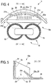
- the wet cleaning device 1a according to 4 and 5 differs only by a different design of the local catcher 19a of the wet cleaning device 1. Consequently, only the essential differences between the collecting device 19 and the collecting device 19a will be discussed in more detail.
- the collecting device 19a has a feed element 22a, which is provided with a plate-shaped extended extension 28.
- the extension 28 is integrally formed on the collecting container 20a and extends substantially horizontally. Based Fig. 4 It can be seen that the extension 28 extends in the cleaning direction R to below the soil working tool 10, so that the disc brushes 13 rest on their extensions in the direction of the catcher 19a facing peripheral portions in sections on the extension 28. In this case, the extension 28 causes an improved supply of solid particles in the collecting container 20a.
- the collecting device 19a has a discharge element 24a, which has a plurality of arranged on the collecting container Drain openings 29 has.
- a damping element 30 is provided which is arranged on a back in the cleaning direction R, inner wall portion 31 of the collecting container 20a.
- the damping element 30 is designed so resilient that by means of the counter-rotating disc brushes 13 in the collecting container 20 a thrown solid particles are slowed down, so that a rebound from the wall portion 31 and from the collecting container 20 a out is avoided.
- the collecting device 19a provides a different type of attachment to the Saugleistenan Aunt 11.
- fastening elements 21a are provided.
- the fastening elements 21a are each designed tab-shaped and provided for releasable connection with unspecified, fixed to the Saugleistenan angel 11 bolt.
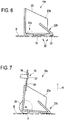
- inventively designed collecting devices 19b, 19c and 19d are based on Fig. 6, 7 or 8 can be seen. In the following, in order to avoid repetition, again only the essential differences of the collecting devices 19b to 19d will be discussed.
- the collecting device 19b after Fig. 6 has a stripping element 32 arranged on the lower side of the collecting container 20b.
- the stripping element 32 has a sealing lip 33 and a textile fabric in the form of a stripping fleece 34.
- the sealing lip 33 is arranged in the cleaning direction R at the front end and below the supply element 22b.
- the stripping fleece 34 is arranged in the cleaning direction R behind the sealing lip 33 and in front of the discharge element 24b.
- both the sealing lip 33 and the Abstreifvlies 34 are on the bottom surface B.
- the stripping element 32 serves to achieve an improved seal between an unspecified underside of the collecting container 20b and the bottom surface B. This avoids that solid particles can be transported under the collecting container 20 b and thus attached to the Saugleistenan Aunt 11.
- the embodiment according to Fig. 7 at least one guide element 35.
- the collecting device 19c more precisely: the collecting container 20c, is mounted floating by means of the guide element 35 in the vertical direction H relative to the suction strip arrangement 11 and / or the soil working tool 10.
- the guide element in the present case has a stud bolt 37 engaging in a slot 36.
- the slot 36 is formed on the collecting device 19c.
- the stud bolt 37 is assigned here the Saugleistenan angel 11 and fixed to this.
- the slot 36 is formed on a tab 38, which is arranged on a cleaning direction R in the rear, inner wall portion of the collecting container 20c.
- the tab 38 can be integrally formed on the collecting container 20c or assembled as a separately manufactured component with the collecting container 20c. In the present case, the latter applies.
- the catching device 19c has a support element 39.
- the support element 39 serves for a rolling support of the collecting container 20c on the bottom surface B.
- the support element is designed in the form of a support wheel 39, which is fixed in rotation about an axis of rotation D to the collecting container 20c.
- the axis of rotation D is arranged in a cleaning direction R in the rear, the Saugleistenan Aunt 11 facing portion of the collecting container 20c.
- apparent operating state of the collecting container 20c is tilted due to the extent eccentric support forward towards the tillage tool and slidably supported on a bottom portion of the feed element 22c on the bottom surface B.
- the basis of the Fig. 8 apparent collecting device 19d designed according to the invention is essentially identical to the collecting device 19a according to FIG Fig. 5 , In contrast to this, however, the collecting device 19d does not provide a plate-shaped extension 28.
- the damping element 30 is made of a non-descript knitted fiber material.
- the common feature of the wet cleaning devices 1 and 1a is that the collecting devices 19, 19a and 19b and 19c there in the cleaning direction R are arranged essentially completely between the soil cultivation tool 10 and the suction strip arrangement 11.
- the collecting container 20e of the collecting device 19e is arranged in the cleaning direction R behind the Saugleistenanowski 11, wherein the supply element 22e starting from the collecting container 20e forward in the direction of the tillage tool 10 across the Saugleistenan Aunt 11 across and obliquely downward toward the bottom surface B is extended.
- Fig. 9 schematically indicated and unspecified solid particles transported along the arrow-shaped trajectory on the Saugleistenan Aunt 11 away into the interior of the collecting container 20 e.
- the collecting device 19f has no collecting container. Instead, the collecting device 19f has a receiving element 40, which rests in the operating state at least partially on the bottom surface B and is designed such that from the tillage tool 10 to the rear transported solid particles on and / or in the receiving element can be collected and collected.
- the receiving element in the present case in the form of a cleaning fleece 40 is formed.
- the cleaning fleece 40 can in particular be made of fibers and / or formed like a sponge.
- the multiplicity of the above-described structural and functional features of the collecting devices 19 to 19f can also be embodied in a single collecting device designed according to the invention, as far as their combination is technically meaningful.
- the features of the collecting devices 19 to 19c may be provided in their entirety or in corresponding sub-combinations on an inventively designed collecting device.
Landscapes
- Cleaning In General (AREA)
- Cleaning By Liquid Or Steam (AREA)
Priority Applications (1)
| Application Number | Priority Date | Filing Date | Title |
|---|---|---|---|
| PL19170616T PL3569128T3 (pl) | 2018-05-14 | 2019-04-23 | Urządzenie do czyszczenia na mokro do czyszczenia na mokro powierzchni podłogi |
Applications Claiming Priority (1)
| Application Number | Priority Date | Filing Date | Title |
|---|---|---|---|
| DE102018207428.3A DE102018207428B3 (de) | 2018-05-14 | 2018-05-14 | Nassreinigungsvorrichtung zur Nassreinigung einer Bodenfläche |
Publications (3)
| Publication Number | Publication Date |
|---|---|
| EP3569128A2 true EP3569128A2 (fr) | 2019-11-20 |
| EP3569128A3 EP3569128A3 (fr) | 2019-12-11 |
| EP3569128B1 EP3569128B1 (fr) | 2021-11-24 |
Family
ID=66248625
Family Applications (1)
| Application Number | Title | Priority Date | Filing Date |
|---|---|---|---|
| EP19170616.7A Active EP3569128B1 (fr) | 2018-05-14 | 2019-04-23 | Dispositif de nettoyage humide destiné au nettoyage humide d'une surface de plancher |
Country Status (7)
| Country | Link |
|---|---|
| US (1) | US11297993B2 (fr) |
| EP (1) | EP3569128B1 (fr) |
| DE (1) | DE102018207428B3 (fr) |
| DK (1) | DK3569128T3 (fr) |
| ES (1) | ES2905913T3 (fr) |
| HU (1) | HUE057410T2 (fr) |
| PL (1) | PL3569128T3 (fr) |
Cited By (4)
| Publication number | Priority date | Publication date | Assignee | Title |
|---|---|---|---|---|
| CN111714038A (zh) * | 2020-06-29 | 2020-09-29 | 苏州高之仙自动化科技有限公司 | 一种清洁机器人 |
| WO2024187611A1 (fr) * | 2023-03-10 | 2024-09-19 | 安徽扬子智能制造有限公司 | Appareil de nettoyage à brosse à rouleau et à brosse à disque intégrées |
| US12209609B2 (en) | 2021-06-26 | 2025-01-28 | Tennant Company | Torque transmitting ball joint |
| WO2025233515A3 (fr) * | 2024-05-10 | 2026-01-29 | I-Mop Gmbh | Tête de nettoyage de surface pour un appareil de nettoyage de surface |
Families Citing this family (5)
| Publication number | Priority date | Publication date | Assignee | Title |
|---|---|---|---|---|
| USD989424S1 (en) | 2020-04-13 | 2023-06-13 | Karma 360, Inc. | Upright floor scrubber |
| US11771292B1 (en) | 2020-09-10 | 2023-10-03 | Karma 360, Inc. | Floor scrubber apparatus with releasably locking handle |
| CN112021185A (zh) * | 2020-10-08 | 2020-12-04 | 康新峰 | 一种牛羊养殖消毒清洗装置 |
| JP1804318S (ja) * | 2023-12-29 | 2025-07-23 | 床洗浄機 | |
| USD1114441S1 (en) * | 2024-02-05 | 2026-02-17 | Beijing Roborock Technology Co., Ltd. | Floor washing appliance |
Citations (1)
| Publication number | Priority date | Publication date | Assignee | Title |
|---|---|---|---|---|
| EP2832277A2 (fr) | 2013-08-02 | 2015-02-04 | i-mop GmbH | Appareil portatif de traitement des sols |
Family Cites Families (3)
| Publication number | Priority date | Publication date | Assignee | Title |
|---|---|---|---|---|
| IT1239825B (it) * | 1990-03-26 | 1993-11-15 | Dulevo Spa | Macchina di lavaggio e pulizia di superfici,particolarmente di pavimentazioni industriali |
| US6990709B2 (en) * | 2002-10-11 | 2006-01-31 | Surtec, Inc. | Vacuum sweeping system for automatic scrubber |
| DE102015103500A1 (de) * | 2015-03-10 | 2016-09-15 | Industrialpartners Gmbh | Reinigungsgerät |
-
2018
- 2018-05-14 DE DE102018207428.3A patent/DE102018207428B3/de active Active
-
2019
- 2019-04-23 PL PL19170616T patent/PL3569128T3/pl unknown
- 2019-04-23 EP EP19170616.7A patent/EP3569128B1/fr active Active
- 2019-04-23 ES ES19170616T patent/ES2905913T3/es active Active
- 2019-04-23 DK DK19170616.7T patent/DK3569128T3/da active
- 2019-04-23 HU HUE19170616A patent/HUE057410T2/hu unknown
- 2019-05-09 US US16/407,677 patent/US11297993B2/en active Active
Patent Citations (1)
| Publication number | Priority date | Publication date | Assignee | Title |
|---|---|---|---|---|
| EP2832277A2 (fr) | 2013-08-02 | 2015-02-04 | i-mop GmbH | Appareil portatif de traitement des sols |
Cited By (4)
| Publication number | Priority date | Publication date | Assignee | Title |
|---|---|---|---|---|
| CN111714038A (zh) * | 2020-06-29 | 2020-09-29 | 苏州高之仙自动化科技有限公司 | 一种清洁机器人 |
| US12209609B2 (en) | 2021-06-26 | 2025-01-28 | Tennant Company | Torque transmitting ball joint |
| WO2024187611A1 (fr) * | 2023-03-10 | 2024-09-19 | 安徽扬子智能制造有限公司 | Appareil de nettoyage à brosse à rouleau et à brosse à disque intégrées |
| WO2025233515A3 (fr) * | 2024-05-10 | 2026-01-29 | I-Mop Gmbh | Tête de nettoyage de surface pour un appareil de nettoyage de surface |
Also Published As
| Publication number | Publication date |
|---|---|
| EP3569128A3 (fr) | 2019-12-11 |
| DE102018207428B3 (de) | 2019-05-23 |
| ES2905913T3 (es) | 2022-04-12 |
| DK3569128T3 (da) | 2022-02-07 |
| HUE057410T2 (hu) | 2022-05-28 |
| US20190343357A1 (en) | 2019-11-14 |
| EP3569128B1 (fr) | 2021-11-24 |
| US11297993B2 (en) | 2022-04-12 |
| PL3569128T3 (pl) | 2022-05-02 |
Similar Documents
| Publication | Publication Date | Title |
|---|---|---|
| DE102018207428B3 (de) | Nassreinigungsvorrichtung zur Nassreinigung einer Bodenfläche | |
| EP3206548B1 (fr) | Machine de nettoyage de surfaces et procédé permettant de faire fonctionner une machine de nettoyage de surfaces | |
| EP3206551B1 (fr) | Machine de nettoyage de surfaces | |
| EP2939582B1 (fr) | Buse d'aspirateur | |
| DE3024113A1 (de) | Reinigungskopf zur reinigung von planen flaechen | |
| DE19612133A1 (de) | Wischblatt für eine Fahrzeugscheibenwischervorrichtung | |
| DE102012105734A1 (de) | Fahrbare Bodenreinigungsmaschine | |
| EP3761840B1 (fr) | Appareil de nettoyage | |
| DE202014011488U1 (de) | Tragbares Sauggerät | |
| DE202007017026U1 (de) | Bodenreinigungsgerät mit einer Reinigungswalze | |
| DE102007034702A1 (de) | Schmutzaufnahmevorrichtung für eine Bodenreinigungsmaschine sowie Bodenreinigungsmaschine mit einer derartigen Schmutzaufnahmevorrichtung | |
| EP3225146B1 (fr) | Procede de nettoyage de sols et machine de nettoyage de sol | |
| DE602004007519T2 (de) | Moppanordnung und mopp mit einer solchen moppanordnung | |
| DE19719495A1 (de) | Wischanordnung für eine Bodenreinigungsmaschine | |
| DE10221352B4 (de) | Bodenreinigungsmaschine | |
| DE10221349A1 (de) | Bodenreinigungsmaschine | |
| EP1935307A2 (fr) | Buse de sol pour aspirateur | |
| DE102015105228B4 (de) | Vorrichtung für ein ein saugendes Gebläse aufweisendes Reinigungsgerät | |
| DE102011076489A1 (de) | Kehrmaschine mit Absaugsystem | |
| EP0917437B1 (fr) | Dispositif pour nettoyer le sol par lavage et par aspiration | |
| EP2534991B1 (fr) | Buse de sol pour un aspirateur et aspirateur doté d'une telle buse de sol | |
| EP3188636B1 (fr) | Dispositif de rampe d'aspiration pour une machine de nettoyage de sol, machine de nettoyage de sol et procédé pour le nettoyage de sols carrelés | |
| DE202018003947U1 (de) | Saugkehrvorrichtung | |
| EP3923775B1 (fr) | Buse de sol pour un dispositif de nettoyage avec fonction d'aspiration, dispositif de nettoyage et procédé pour aspirer une surface de sol | |
| DE3602926A1 (de) | Saugduese |
Legal Events
| Date | Code | Title | Description |
|---|---|---|---|
| PUAI | Public reference made under article 153(3) epc to a published international application that has entered the european phase |
Free format text: ORIGINAL CODE: 0009012 |
|
| STAA | Information on the status of an ep patent application or granted ep patent |
Free format text: STATUS: THE APPLICATION HAS BEEN PUBLISHED |
|
| PUAL | Search report despatched |
Free format text: ORIGINAL CODE: 0009013 |
|
| AK | Designated contracting states |
Kind code of ref document: A2 Designated state(s): AL AT BE BG CH CY CZ DE DK EE ES FI FR GB GR HR HU IE IS IT LI LT LU LV MC MK MT NL NO PL PT RO RS SE SI SK SM TR |
|
| AX | Request for extension of the european patent |
Extension state: BA ME |
|
| AK | Designated contracting states |
Kind code of ref document: A3 Designated state(s): AL AT BE BG CH CY CZ DE DK EE ES FI FR GB GR HR HU IE IS IT LI LT LU LV MC MK MT NL NO PL PT RO RS SE SI SK SM TR |
|
| AX | Request for extension of the european patent |
Extension state: BA ME |
|
| RIC1 | Information provided on ipc code assigned before grant |
Ipc: A47L 11/00 20060101AFI20191105BHEP |
|
| STAA | Information on the status of an ep patent application or granted ep patent |
Free format text: STATUS: REQUEST FOR EXAMINATION WAS MADE |
|
| 17P | Request for examination filed |
Effective date: 20200309 |
|
| RBV | Designated contracting states (corrected) |
Designated state(s): AL AT BE BG CH CY CZ DE DK EE ES FI FR GB GR HR HU IE IS IT LI LT LU LV MC MK MT NL NO PL PT RO RS SE SI SK SM TR |
|
| GRAP | Despatch of communication of intention to grant a patent |
Free format text: ORIGINAL CODE: EPIDOSNIGR1 |
|
| STAA | Information on the status of an ep patent application or granted ep patent |
Free format text: STATUS: GRANT OF PATENT IS INTENDED |
|
| INTG | Intention to grant announced |
Effective date: 20210913 |
|
| GRAS | Grant fee paid |
Free format text: ORIGINAL CODE: EPIDOSNIGR3 |
|
| GRAA | (expected) grant |
Free format text: ORIGINAL CODE: 0009210 |
|
| STAA | Information on the status of an ep patent application or granted ep patent |
Free format text: STATUS: THE PATENT HAS BEEN GRANTED |
|
| AK | Designated contracting states |
Kind code of ref document: B1 Designated state(s): AL AT BE BG CH CY CZ DE DK EE ES FI FR GB GR HR HU IE IS IT LI LT LU LV MC MK MT NL NO PL PT RO RS SE SI SK SM TR |
|
| REG | Reference to a national code |
Ref country code: GB Ref legal event code: FG4D Free format text: NOT ENGLISH |
|
| REG | Reference to a national code |
Ref country code: AT Ref legal event code: REF Ref document number: 1449208 Country of ref document: AT Kind code of ref document: T Effective date: 20211215 |
|
| REG | Reference to a national code |
Ref country code: DE Ref legal event code: R096 Ref document number: 502019002813 Country of ref document: DE |
|
| REG | Reference to a national code |
Ref country code: IE Ref legal event code: FG4D Free format text: LANGUAGE OF EP DOCUMENT: GERMAN |
|
| REG | Reference to a national code |
Ref country code: DK Ref legal event code: T3 Effective date: 20220203 |
|
| REG | Reference to a national code |
Ref country code: NL Ref legal event code: FP |
|
| REG | Reference to a national code |
Ref country code: SE Ref legal event code: TRGR |
|
| REG | Reference to a national code |
Ref country code: LT Ref legal event code: MG9D |
|
| REG | Reference to a national code |
Ref country code: ES Ref legal event code: FG2A Ref document number: 2905913 Country of ref document: ES Kind code of ref document: T3 Effective date: 20220412 |
|
| PG25 | Lapsed in a contracting state [announced via postgrant information from national office to epo] |
Ref country code: RS Free format text: LAPSE BECAUSE OF FAILURE TO SUBMIT A TRANSLATION OF THE DESCRIPTION OR TO PAY THE FEE WITHIN THE PRESCRIBED TIME-LIMIT Effective date: 20211124 Ref country code: LT Free format text: LAPSE BECAUSE OF FAILURE TO SUBMIT A TRANSLATION OF THE DESCRIPTION OR TO PAY THE FEE WITHIN THE PRESCRIBED TIME-LIMIT Effective date: 20211124 Ref country code: FI Free format text: LAPSE BECAUSE OF FAILURE TO SUBMIT A TRANSLATION OF THE DESCRIPTION OR TO PAY THE FEE WITHIN THE PRESCRIBED TIME-LIMIT Effective date: 20211124 Ref country code: BG Free format text: LAPSE BECAUSE OF FAILURE TO SUBMIT A TRANSLATION OF THE DESCRIPTION OR TO PAY THE FEE WITHIN THE PRESCRIBED TIME-LIMIT Effective date: 20220224 |
|
| REG | Reference to a national code |
Ref country code: HU Ref legal event code: AG4A Ref document number: E057410 Country of ref document: HU |
|
| PG25 | Lapsed in a contracting state [announced via postgrant information from national office to epo] |
Ref country code: IS Free format text: LAPSE BECAUSE OF FAILURE TO SUBMIT A TRANSLATION OF THE DESCRIPTION OR TO PAY THE FEE WITHIN THE PRESCRIBED TIME-LIMIT Effective date: 20220324 Ref country code: PT Free format text: LAPSE BECAUSE OF FAILURE TO SUBMIT A TRANSLATION OF THE DESCRIPTION OR TO PAY THE FEE WITHIN THE PRESCRIBED TIME-LIMIT Effective date: 20220324 Ref country code: NO Free format text: LAPSE BECAUSE OF FAILURE TO SUBMIT A TRANSLATION OF THE DESCRIPTION OR TO PAY THE FEE WITHIN THE PRESCRIBED TIME-LIMIT Effective date: 20220224 Ref country code: LV Free format text: LAPSE BECAUSE OF FAILURE TO SUBMIT A TRANSLATION OF THE DESCRIPTION OR TO PAY THE FEE WITHIN THE PRESCRIBED TIME-LIMIT Effective date: 20211124 Ref country code: HR Free format text: LAPSE BECAUSE OF FAILURE TO SUBMIT A TRANSLATION OF THE DESCRIPTION OR TO PAY THE FEE WITHIN THE PRESCRIBED TIME-LIMIT Effective date: 20211124 Ref country code: GR Free format text: LAPSE BECAUSE OF FAILURE TO SUBMIT A TRANSLATION OF THE DESCRIPTION OR TO PAY THE FEE WITHIN THE PRESCRIBED TIME-LIMIT Effective date: 20220225 |
|
| PG25 | Lapsed in a contracting state [announced via postgrant information from national office to epo] |
Ref country code: SM Free format text: LAPSE BECAUSE OF FAILURE TO SUBMIT A TRANSLATION OF THE DESCRIPTION OR TO PAY THE FEE WITHIN THE PRESCRIBED TIME-LIMIT Effective date: 20211124 Ref country code: SK Free format text: LAPSE BECAUSE OF FAILURE TO SUBMIT A TRANSLATION OF THE DESCRIPTION OR TO PAY THE FEE WITHIN THE PRESCRIBED TIME-LIMIT Effective date: 20211124 Ref country code: RO Free format text: LAPSE BECAUSE OF FAILURE TO SUBMIT A TRANSLATION OF THE DESCRIPTION OR TO PAY THE FEE WITHIN THE PRESCRIBED TIME-LIMIT Effective date: 20211124 Ref country code: EE Free format text: LAPSE BECAUSE OF FAILURE TO SUBMIT A TRANSLATION OF THE DESCRIPTION OR TO PAY THE FEE WITHIN THE PRESCRIBED TIME-LIMIT Effective date: 20211124 Ref country code: CZ Free format text: LAPSE BECAUSE OF FAILURE TO SUBMIT A TRANSLATION OF THE DESCRIPTION OR TO PAY THE FEE WITHIN THE PRESCRIBED TIME-LIMIT Effective date: 20211124 |
|
| REG | Reference to a national code |
Ref country code: DE Ref legal event code: R097 Ref document number: 502019002813 Country of ref document: DE |
|
| PLBE | No opposition filed within time limit |
Free format text: ORIGINAL CODE: 0009261 |
|
| STAA | Information on the status of an ep patent application or granted ep patent |
Free format text: STATUS: NO OPPOSITION FILED WITHIN TIME LIMIT |
|
| PG25 | Lapsed in a contracting state [announced via postgrant information from national office to epo] |
Ref country code: AL Free format text: LAPSE BECAUSE OF FAILURE TO SUBMIT A TRANSLATION OF THE DESCRIPTION OR TO PAY THE FEE WITHIN THE PRESCRIBED TIME-LIMIT Effective date: 20211124 |
|
| 26N | No opposition filed |
Effective date: 20220825 |
|
| PG25 | Lapsed in a contracting state [announced via postgrant information from national office to epo] |
Ref country code: SI Free format text: LAPSE BECAUSE OF FAILURE TO SUBMIT A TRANSLATION OF THE DESCRIPTION OR TO PAY THE FEE WITHIN THE PRESCRIBED TIME-LIMIT Effective date: 20211124 |
|
| REG | Reference to a national code |
Ref country code: BE Ref legal event code: MM Effective date: 20220430 |
|
| PG25 | Lapsed in a contracting state [announced via postgrant information from national office to epo] |
Ref country code: MC Free format text: LAPSE BECAUSE OF FAILURE TO SUBMIT A TRANSLATION OF THE DESCRIPTION OR TO PAY THE FEE WITHIN THE PRESCRIBED TIME-LIMIT Effective date: 20211124 Ref country code: LU Free format text: LAPSE BECAUSE OF NON-PAYMENT OF DUE FEES Effective date: 20220423 |
|
| PG25 | Lapsed in a contracting state [announced via postgrant information from national office to epo] |
Ref country code: BE Free format text: LAPSE BECAUSE OF NON-PAYMENT OF DUE FEES Effective date: 20220430 |
|
| PG25 | Lapsed in a contracting state [announced via postgrant information from national office to epo] |
Ref country code: IE Free format text: LAPSE BECAUSE OF NON-PAYMENT OF DUE FEES Effective date: 20220423 |
|
| P01 | Opt-out of the competence of the unified patent court (upc) registered |
Effective date: 20230519 |
|
| PG25 | Lapsed in a contracting state [announced via postgrant information from national office to epo] |
Ref country code: MK Free format text: LAPSE BECAUSE OF FAILURE TO SUBMIT A TRANSLATION OF THE DESCRIPTION OR TO PAY THE FEE WITHIN THE PRESCRIBED TIME-LIMIT Effective date: 20211124 Ref country code: CY Free format text: LAPSE BECAUSE OF FAILURE TO SUBMIT A TRANSLATION OF THE DESCRIPTION OR TO PAY THE FEE WITHIN THE PRESCRIBED TIME-LIMIT Effective date: 20211124 |
|
| PG25 | Lapsed in a contracting state [announced via postgrant information from national office to epo] |
Ref country code: MT Free format text: LAPSE BECAUSE OF FAILURE TO SUBMIT A TRANSLATION OF THE DESCRIPTION OR TO PAY THE FEE WITHIN THE PRESCRIBED TIME-LIMIT Effective date: 20211124 |
|
| PGFP | Annual fee paid to national office [announced via postgrant information from national office to epo] |
Ref country code: NL Payment date: 20250422 Year of fee payment: 7 |
|
| REG | Reference to a national code |
Ref country code: AT Ref legal event code: MM01 Ref document number: 1449208 Country of ref document: AT Kind code of ref document: T Effective date: 20240423 |
|
| PGFP | Annual fee paid to national office [announced via postgrant information from national office to epo] |
Ref country code: DE Payment date: 20250422 Year of fee payment: 7 |
|
| PGFP | Annual fee paid to national office [announced via postgrant information from national office to epo] |
Ref country code: ES Payment date: 20250519 Year of fee payment: 7 Ref country code: DK Payment date: 20250423 Year of fee payment: 7 |
|
| PGFP | Annual fee paid to national office [announced via postgrant information from national office to epo] |
Ref country code: HU Payment date: 20250425 Year of fee payment: 7 |
|
| PGFP | Annual fee paid to national office [announced via postgrant information from national office to epo] |
Ref country code: IT Payment date: 20250430 Year of fee payment: 7 |
|
| PGFP | Annual fee paid to national office [announced via postgrant information from national office to epo] |
Ref country code: FR Payment date: 20250422 Year of fee payment: 7 |
|
| PGFP | Annual fee paid to national office [announced via postgrant information from national office to epo] |
Ref country code: CH Payment date: 20250501 Year of fee payment: 7 |
|
| PG25 | Lapsed in a contracting state [announced via postgrant information from national office to epo] |
Ref country code: AT Free format text: LAPSE BECAUSE OF NON-PAYMENT OF DUE FEES Effective date: 20240423 |
|
| PGFP | Annual fee paid to national office [announced via postgrant information from national office to epo] |
Ref country code: TR Payment date: 20250415 Year of fee payment: 7 |
|
| PGFP | Annual fee paid to national office [announced via postgrant information from national office to epo] |
Ref country code: SE Payment date: 20250423 Year of fee payment: 7 |
|
| PGFP | Annual fee paid to national office [announced via postgrant information from national office to epo] |
Ref country code: GB Payment date: 20260327 Year of fee payment: 8 |
|
| PGFP | Annual fee paid to national office [announced via postgrant information from national office to epo] |
Ref country code: AT Payment date: 20260410 Year of fee payment: 5 |
|
| PGFP | Annual fee paid to national office [announced via postgrant information from national office to epo] |
Ref country code: PL Payment date: 20260326 Year of fee payment: 8 |