EP2832277A2 - Appareil portatif de traitement des sols - Google Patents
Appareil portatif de traitement des sols Download PDFInfo
- Publication number
- EP2832277A2 EP2832277A2 EP14177128.7A EP14177128A EP2832277A2 EP 2832277 A2 EP2832277 A2 EP 2832277A2 EP 14177128 A EP14177128 A EP 14177128A EP 2832277 A2 EP2832277 A2 EP 2832277A2
- Authority
- EP
- European Patent Office
- Prior art keywords
- bottom part
- soil cultivation
- cultivation device
- suction
- saugleistenanordnung
- Prior art date
- Legal status (The legal status is an assumption and is not a legal conclusion. Google has not performed a legal analysis and makes no representation as to the accuracy of the status listed.)
- Granted
Links
Images



Classifications
-
- A—HUMAN NECESSITIES
- A47—FURNITURE; DOMESTIC ARTICLES OR APPLIANCES; COFFEE MILLS; SPICE MILLS; SUCTION CLEANERS IN GENERAL
- A47L—DOMESTIC WASHING OR CLEANING; SUCTION CLEANERS IN GENERAL
- A47L11/00—Machines for cleaning floors, carpets, furniture, walls, or wall coverings
- A47L11/40—Parts or details of machines not provided for in groups A47L11/02 - A47L11/38, or not restricted to one of these groups, e.g. handles, arrangements of switches, skirts, buffers, levers
- A47L11/408—Means for supplying cleaning or surface treating agents
- A47L11/4088—Supply pumps; Spraying devices; Supply conduits
-
- A—HUMAN NECESSITIES
- A47—FURNITURE; DOMESTIC ARTICLES OR APPLIANCES; COFFEE MILLS; SPICE MILLS; SUCTION CLEANERS IN GENERAL
- A47L—DOMESTIC WASHING OR CLEANING; SUCTION CLEANERS IN GENERAL
- A47L11/00—Machines for cleaning floors, carpets, furniture, walls, or wall coverings
-
- A—HUMAN NECESSITIES
- A47—FURNITURE; DOMESTIC ARTICLES OR APPLIANCES; COFFEE MILLS; SPICE MILLS; SUCTION CLEANERS IN GENERAL
- A47L—DOMESTIC WASHING OR CLEANING; SUCTION CLEANERS IN GENERAL
- A47L11/00—Machines for cleaning floors, carpets, furniture, walls, or wall coverings
- A47L11/02—Floor surfacing or polishing machines
- A47L11/04—Floor surfacing or polishing machines hand-driven
- A47L11/08—Floor surfacing or polishing machines hand-driven with rotating tools
-
- A—HUMAN NECESSITIES
- A47—FURNITURE; DOMESTIC ARTICLES OR APPLIANCES; COFFEE MILLS; SPICE MILLS; SUCTION CLEANERS IN GENERAL
- A47L—DOMESTIC WASHING OR CLEANING; SUCTION CLEANERS IN GENERAL
- A47L11/00—Machines for cleaning floors, carpets, furniture, walls, or wall coverings
- A47L11/02—Floor surfacing or polishing machines
- A47L11/20—Floor surfacing or polishing machines combined with vacuum cleaning devices
- A47L11/202—Floor surfacing or polishing machines combined with vacuum cleaning devices having separate drive for the cleaning brushes
- A47L11/2025—Floor surfacing or polishing machines combined with vacuum cleaning devices having separate drive for the cleaning brushes the tools being disc brushes
-
- A—HUMAN NECESSITIES
- A47—FURNITURE; DOMESTIC ARTICLES OR APPLIANCES; COFFEE MILLS; SPICE MILLS; SUCTION CLEANERS IN GENERAL
- A47L—DOMESTIC WASHING OR CLEANING; SUCTION CLEANERS IN GENERAL
- A47L11/00—Machines for cleaning floors, carpets, furniture, walls, or wall coverings
- A47L11/26—Floor-scrubbing machines, hand-driven
-
- A—HUMAN NECESSITIES
- A47—FURNITURE; DOMESTIC ARTICLES OR APPLIANCES; COFFEE MILLS; SPICE MILLS; SUCTION CLEANERS IN GENERAL
- A47L—DOMESTIC WASHING OR CLEANING; SUCTION CLEANERS IN GENERAL
- A47L11/00—Machines for cleaning floors, carpets, furniture, walls, or wall coverings
- A47L11/29—Floor-scrubbing machines characterised by means for taking-up dirty liquid
- A47L11/30—Floor-scrubbing machines characterised by means for taking-up dirty liquid by suction
- A47L11/302—Floor-scrubbing machines characterised by means for taking-up dirty liquid by suction having rotary tools
- A47L11/305—Floor-scrubbing machines characterised by means for taking-up dirty liquid by suction having rotary tools the tools being disc brushes
-
- A—HUMAN NECESSITIES
- A47—FURNITURE; DOMESTIC ARTICLES OR APPLIANCES; COFFEE MILLS; SPICE MILLS; SUCTION CLEANERS IN GENERAL
- A47L—DOMESTIC WASHING OR CLEANING; SUCTION CLEANERS IN GENERAL
- A47L11/00—Machines for cleaning floors, carpets, furniture, walls, or wall coverings
- A47L11/40—Parts or details of machines not provided for in groups A47L11/02 - A47L11/38, or not restricted to one of these groups, e.g. handles, arrangements of switches, skirts, buffers, levers
- A47L11/4013—Contaminants collecting devices, i.e. hoppers, tanks or the like
- A47L11/4016—Contaminants collecting devices, i.e. hoppers, tanks or the like specially adapted for collecting fluids
-
- A—HUMAN NECESSITIES
- A47—FURNITURE; DOMESTIC ARTICLES OR APPLIANCES; COFFEE MILLS; SPICE MILLS; SUCTION CLEANERS IN GENERAL
- A47L—DOMESTIC WASHING OR CLEANING; SUCTION CLEANERS IN GENERAL
- A47L11/00—Machines for cleaning floors, carpets, furniture, walls, or wall coverings
- A47L11/40—Parts or details of machines not provided for in groups A47L11/02 - A47L11/38, or not restricted to one of these groups, e.g. handles, arrangements of switches, skirts, buffers, levers
- A47L11/4063—Driving means; Transmission means therefor
-
- A—HUMAN NECESSITIES
- A47—FURNITURE; DOMESTIC ARTICLES OR APPLIANCES; COFFEE MILLS; SPICE MILLS; SUCTION CLEANERS IN GENERAL
- A47L—DOMESTIC WASHING OR CLEANING; SUCTION CLEANERS IN GENERAL
- A47L11/00—Machines for cleaning floors, carpets, furniture, walls, or wall coverings
- A47L11/40—Parts or details of machines not provided for in groups A47L11/02 - A47L11/38, or not restricted to one of these groups, e.g. handles, arrangements of switches, skirts, buffers, levers
- A47L11/4063—Driving means; Transmission means therefor
- A47L11/4066—Propulsion of the whole machine
-
- A—HUMAN NECESSITIES
- A47—FURNITURE; DOMESTIC ARTICLES OR APPLIANCES; COFFEE MILLS; SPICE MILLS; SUCTION CLEANERS IN GENERAL
- A47L—DOMESTIC WASHING OR CLEANING; SUCTION CLEANERS IN GENERAL
- A47L11/00—Machines for cleaning floors, carpets, furniture, walls, or wall coverings
- A47L11/40—Parts or details of machines not provided for in groups A47L11/02 - A47L11/38, or not restricted to one of these groups, e.g. handles, arrangements of switches, skirts, buffers, levers
- A47L11/4072—Arrangement of castors or wheels
-
- A—HUMAN NECESSITIES
- A47—FURNITURE; DOMESTIC ARTICLES OR APPLIANCES; COFFEE MILLS; SPICE MILLS; SUCTION CLEANERS IN GENERAL
- A47L—DOMESTIC WASHING OR CLEANING; SUCTION CLEANERS IN GENERAL
- A47L11/00—Machines for cleaning floors, carpets, furniture, walls, or wall coverings
- A47L11/40—Parts or details of machines not provided for in groups A47L11/02 - A47L11/38, or not restricted to one of these groups, e.g. handles, arrangements of switches, skirts, buffers, levers
- A47L11/4075—Handles; levers
-
- A—HUMAN NECESSITIES
- A47—FURNITURE; DOMESTIC ARTICLES OR APPLIANCES; COFFEE MILLS; SPICE MILLS; SUCTION CLEANERS IN GENERAL
- A47L—DOMESTIC WASHING OR CLEANING; SUCTION CLEANERS IN GENERAL
- A47L11/00—Machines for cleaning floors, carpets, furniture, walls, or wall coverings
- A47L11/40—Parts or details of machines not provided for in groups A47L11/02 - A47L11/38, or not restricted to one of these groups, e.g. handles, arrangements of switches, skirts, buffers, levers
- A47L11/408—Means for supplying cleaning or surface treating agents
- A47L11/4083—Liquid supply reservoirs; Preparation of the agents, e.g. mixing devices
-
- A—HUMAN NECESSITIES
- A47—FURNITURE; DOMESTIC ARTICLES OR APPLIANCES; COFFEE MILLS; SPICE MILLS; SUCTION CLEANERS IN GENERAL
- A47L—DOMESTIC WASHING OR CLEANING; SUCTION CLEANERS IN GENERAL
- A47L11/00—Machines for cleaning floors, carpets, furniture, walls, or wall coverings
- A47L11/40—Parts or details of machines not provided for in groups A47L11/02 - A47L11/38, or not restricted to one of these groups, e.g. handles, arrangements of switches, skirts, buffers, levers
- A47L11/4091—Storing or parking devices, arrangements therefor; Means allowing transport of the machine when it is not being used
-
- A—HUMAN NECESSITIES
- A47—FURNITURE; DOMESTIC ARTICLES OR APPLIANCES; COFFEE MILLS; SPICE MILLS; SUCTION CLEANERS IN GENERAL
- A47L—DOMESTIC WASHING OR CLEANING; SUCTION CLEANERS IN GENERAL
- A47L23/00—Cleaning footwear
- A47L23/22—Devices or implements resting on the floor for removing mud, dirt, or dust from footwear
- A47L23/26—Mats or gratings combined with brushes ; Mats
- A47L23/266—Mats
-
- A—HUMAN NECESSITIES
- A47—FURNITURE; DOMESTIC ARTICLES OR APPLIANCES; COFFEE MILLS; SPICE MILLS; SUCTION CLEANERS IN GENERAL
- A47L—DOMESTIC WASHING OR CLEANING; SUCTION CLEANERS IN GENERAL
- A47L7/00—Suction cleaners adapted for additional purposes; Tables with suction openings for cleaning purposes; Containers for cleaning articles by suction; Suction cleaners adapted to cleaning of brushes; Suction cleaners adapted to taking-up liquids
- A47L7/0004—Suction cleaners adapted to take up liquids, e.g. wet or dry vacuum cleaners
- A47L7/0023—Recovery tanks
Definitions
- the at least one rotatable tool is arranged on the bottom part, that during operation of the harrow, the at least one rotatable Tool exerts a permanent linear propulsion on the bottom part.
- the at least one tool is rotatable exclusively in the direction of advance. An operator therefore no longer has to pull or push the soil cultivation device according to the invention into the corresponding processing direction, as is the case in the prior art. Rather, the operator only has to make a control of the self-propelled moving floor part.
- a particularly simple control of the harrow by an operator can be achieved because a simple, initiated manually via the at least one rotary movement on the guide member in each angular position of the guide member relative to the bottom part ensures a corresponding torque transmission to the bottom part, so that the direction the bottom part can be changed via a control of the guide part.
- an extremely small amount of force is necessary to control the harrow. Due to the great flexibility of the guide part relative to the bottom part also floors can be easily edited even in hard to reach areas.
- the solution according to the invention is provided both for dry tillage equipment and for wet working tillage equipment.
- both tools are provided with approximately vertically oriented axis of rotation and tools with approximately horizontally oriented axis of rotation.
- the at least one rotatable tool is arranged relative to the base part in such a way that, during operation, a linear advance of the base part results through the tool rotating on the floor. This means that the bottom part constantly moves in a straight line forward during the operation of the at least one tool, as long as no control process is initiated by corresponding pivoting of the guide member.
- At least one rotatable tool in the form of a roller or brush which is mounted with a horizontal axis of rotation in the bottom part, causes a rotation of the at least one tool in the advancing direction inevitably a linear forward movement of the bottom part.
- a single, brush or roller-shaped tool is provided.
- at least two roller or brush-shaped tools, each having a horizontal axis of rotation can be arranged next to one another or one behind the other.
- a correspondingly linear propulsion arises in this alternative through a synchronized drive control of the at least two tools.
- successively arranged tools with horizontal axis of rotation these can also rotate in opposite directions, as long as acting on the ground, resulting driving force for the bottom part is achieved.
- the harrow is designed as a wet cleaning machine, in particular as a scouring-suction machine, and has a - seen in the advancing direction - behind the rotatable tool arranged, resting on the ground in operation Saugleistenan Mr.
- the Saugleistenan Mr comprises at least one extending over a processing width of the bottom part and resting on the floor sealing lip.
- two substantially mutually parallel sealing lips are provided, between which a corresponding suction by at least one suction nozzle of a suction system of the wet cleaning machine is formed.
- the Saugleistenan angel is arcuately curved.
- the Saugleistenan Aunt may also include a plurality of juxtaposed or successively arranged Saugleistenabête.
- a single or multiple-part designed Saugleistenanaku is provided, which is arranged behind the at least one rotatable tool. Since the at least one rotatable tool during operation of the wet cleaning machine exerts a permanent linear propulsion, it is ensured that the desired cleaning effect is achieved permanently by a simple, automatic forward movement of the bottom part. By means of the hand-held guide part of the self-propelled moving floor part is controlled.
- first of all fresh water is supplied with or without cleaning additives in the area of the at least one rotatable tool, which first has a corresponding scouring or scrubbing operation through the supports at least one rotating tool. Subsequently, the generated dirty water is sucked up behind the at least one rotating tool by the tracked Saugleistenan Aunt and discharged into a recovery tank.
- the joint arrangement comprises at least two mutually different, in particular mutually orthogonal, hinge axes which are each different to a vertical axis of the guide member, in particular orthogonal, aligned.
- the vertical axis of the guide part is to be understood as meaning a central longitudinal axis in the longitudinal extent of the guide part which extends in the vertical direction of the tillage device when the guide part is oriented vertically relative to a floor and relative to the floor part.
- the two hinge axes are aligned orthogonal to each other.
- the hinge axes In order to ensure that in each angular position of the guide member relative to the vertical torque transmission can be exerted on the bottom part, the hinge axes must also different to the vertical axis of the guide member, in particular orthogonal aligned. This ensures that in a rotational movement of the guide member about its vertical axis, which is initiated manually, in each angular position of the guide member relative to the bottom part of a torque is transmitted to the bottom part.
- the possibility of torque transmission of the guide member to the bottom part is limited to angular positions of the guide member relative to the vertical of less than 45 to 50 °.
- the joint axes can be present in real terms by corresponding mechanical joint designs. Alternatively, the hinge axes may also be provided virtually or imaginarily within at least one corresponding solid-body joint forming the hinge assembly.
- the at least two hinge axes are spaced apart in the direction of the vertical axis of the guide part.
- a weight distribution of the guide part is displaced down to the upper hinge axis.
- a center of gravity of the guide part is arranged in the ready state in the region of an upper hinge axis or below the upper hinge axis.
- a ready state is when the scrubber is filled with fresh water (cleaning water) ready for use and the guide member in an upright operating position (at an angle between 0 ° and 45 ° to a vertical).
- a weight distribution of corresponding components within the guide member is designed so that the center of mass of the guide member is located in a lower half of the guide member - based on an entire longitudinal extension of the guide member. Due to the displacement of the center of gravity in the lower half of the guide part, a support of a large part of the weight of the guide part in the region of the joint arrangement is made possible. As a result, in the upper region of the guide part, which comprises the at least one handle, a considerably smaller holding force for the guide part is required by an operator than would be the case if a weight distribution of the guide part were further displaced upwards.
- a lower functional portion of the guide member flanking the hinge assembly at least partially.
- the lower functional portion - as seen in the advancing direction - positioned in front of the hinge assembly, so that is supported at a corresponding inclination of the guide member to the rear of the functional portion in the region of the upper hinge axis.
- a corresponding functional section may be a fresh and / or dirty water tank, which have a relatively large weight in the filled state.
- the suction drive has a relatively large weight, so that also results from the arrangement of the suction drive in the lower region of the guide part shifted to the hinge assembly weight distribution.
- the displacement of the suction drive in the guide part also allows a simplified design of the bottom part, which then essentially only the at least one rotatable tool, an associated rotary drive and the Saugleistenan teaspoon are assigned.
- the bottom part - seen in the forward drive direction, the front supported on the at least one rotatable tool and the rear of the Saugleistenan teaspoon in normal operating position on the ground, and the hinge assembly is articulated in an attack area on the bottom part such that a uniform or front-heavy distribution of a total weight of the harrow on the front and the rear support of the bottom part results on the ground.
- the joint assembly thus attacks at a point on the bottom part, which initiates the weight of the guide member on the bottom part, that a defined distribution of the total weight of the harrow on the front support in the region of at least one rotatable tool on the one hand and on the rear support in the area the Saugleistenan angel other hand.
- a uniform weight distribution means that an at least largely equal distribution takes place on the front and the rear support.
- a front-weighted weight distribution means that in the area of the at least one rotatable tool a support of more than 55% up to a maximum of 90% of the total weight takes place. Due to the described distribution ratios a good cleaning power is ensured by the at least one rotatable tool. For the support of the bottom part on the ground only the at least one rotatable tool and the Saugleistenan teaspoon are necessary.
- the Saugleistenan Aunt is associated with at least one particular rollable or slidable floor spacer, which causes a supplement of at least one sealing lip of the Saugleistenan Ich a support of the bottom part on the floor.
- the bottom spacer ensures that when resting on a floor, a bend of the at least one sealing lip is limited.
- the sealing lip is thereby defined always curved by an equal angle, resulting in a particularly good sealing effect regardless of the nature of a soil surface. This ensures that the at least one sealing lip is not subject to premature wear due to overloading. In addition, it is ensured that the sealing lip does not bend too much.
- rolling or sliding elements can be provided.
- the bottom part comprises a carrier bridge extending along the direction of advance of the bottom part, on which the engagement region of the joint arrangement is provided and which extends around a respective transverse to the direction of advance and parallel to the ground pivot axis on the Saugleistenan Ich one hand and in the region of storage the at least one rotatable tool on the other hand is articulated.
- the support bridge is supported on at least two symmetrically aligned to a vertical central longitudinal plane points on the Saugleistenan whatsoever.
- lowering the squeegee assembly in the course of operation of the wet cleaning machine does not result in inevitable lifting or tilting of the rotatable tool in the area of the front support. Because by the pivot axes described, which are parallel to each other, this results in a static decoupling of the two supports of the bottom part to the ground from each other. This ensures that tilting and tilting movements of the guide part, which are initiated by the operator, have no influence on the position of the Saugleistenan angel.
- the suction and sealing effect of the Saugleistenan inch therefore always remains the same.
- the support bridge carries next to the guide part, which is supported on the hinge assembly on the support bridge, in an electric motor drive for the at least one rotatable tool and an electromotive Suction drive of the suction system and at least one energy storage, preferably in the form of a rechargeable battery, particularly advantageous in the form of a lithium-ion battery.
- the weight of a corresponding accumulator increases pressure on the Saugleistenan Aunt and improves its suction and sealing effect.
- a suction system for a Saugleistenan Aunt associated flow channel in the guide member is arranged coaxially or parallel to the vertical axis of the guide member.
- the idea of this embodiment is to make the guide part as compact as possible and weight-optimized to distribute around the vertical axis of the guide member.
- the laying of the flow channel in the region of the vertical axis of the guide part allows a space-saving design.
- the flow channel can be formed by a flexible hose or a dimensionally stable tube.
- the guide part comprises a longitudinal axis extending along the support tube, in which the flow channel is integrated.
- the support tube has a dual function by serving as a support for the other functional components of the guide part. On the other hand, it forms the flow channel of the suction system.
- a plurality of flow channels of the suction system and / or a Frischwasserzu woolsystems can run.
- at least one cable channel can be integrated in the support tube, in particular by coextrusion. In this cable channel control and power supply cables may be misplaced.
- the suction drive is arranged at a lower end region of the support tube.
- the suction drive is designed as an electric suction turbine, which is coaxially fixed to the lower end portion of the support tube and is directly connected to the running in the support tube flow channel in operative connection. This results in a short suction path for the suction turbine, so that only small suction losses occur. As a result, a lower energy consumption is ensured, which allows a small and weight-saving accumulator.
- fresh and dirty water tanks of the suction system are designed elongated and flank the support tube on opposite sides Pages.
- the fresh and dirty water tanks are grouped directly around the vertical axis of the guide part.
- the distribution of the fresh and dirty water tanks on opposite sides of the support tube results in a particularly good weight distribution on both sides of the vertical axis of the guide part, which greatly simplifies the handling of the guide member by an operator.
- Under fresh water cleaning water is to be understood, which is supplied to the at least one tool and can be designed in particular from water and cleaning additives or as a different running cleaning solution.
- the suction drive - as seen in the advancing direction of the bottom part - positioned in front of the hinge assembly, so that in normal straight-ahead position of the wet cleaning machine, the guide member is placed obliquely backwards and the operator runs behind the bottom part.
- the weight of the guide part, in particular of the suction drive is supported in the region of the upper hinge axis of the hinge arrangement, so that a holding and guiding force in the region of the handle of the guide part for a corresponding operator is extremely low. This allows a simple and energy-saving handling of the wet cleaning machine in its operating state.
- At least one support means is provided on the bottom part, which supports the bottom part in a tilted transport or storage position statically determined on the ground.
- the at least one support means is designed as a sliding or roll-movable support element.
- the at least one sliding or rolling movable support element therefore also serves to transport the harrow, if this is not in its operating state.
- the guide member on the bottom part in the transport or storage position of the bottom part by means of at least one securing means in a rest position secured by force, in particular the guide member and the bottom part are supported statically determined in an over-center position relative to each other.
- the force-limited securing means of the securing means ensures that the guide member can be released from the bottom part in a simple manner and with little effort again to transfer the bottom part and the guide member in the operating position.
- the guide part and the bottom part are statically supported in an over-center position relative to each other. This means that the guide part over the at least one hinge axis of the joint assembly is pivoted relative to the bottom part so far above the bottom part, that the center of mass of the guide member is positioned above the bottom part.
- the at least one securing means is positively or positively effective.
- the at least one securing means can be mechanically non-positively or positively effective.
- the frictional connection is generated by the at least one securing means by magnetic force.
- a mechanically force-locking or form-locking effective securing means can be implemented by a releasable latching connection, by a hook-and-loop fastener or a differently designed adhesive fastener.
- a permanent magnet is preferably provided on the guide part or on the bottom part, which is opposite to a corresponding counterpart on the bottom part or on the guide part, a magnetizable surface, in particular a metallic surface.
- the invention also relates to a soil cultivation system with a hand-held soil cultivating device, as described above, as well as with a storage trolley, the at least one replaceable and filled fresh water tank and at least one receptacle for a filled waste water tank and / or a dirty water receptacle whose volume corresponds to at least twice the volume of a waste water tank.
- the storage trolley complementarily also hold at least one accumulator, so that if necessary, an exchange of the accumulator can be done on the scrubber without much effort. This makes it possible to work even larger floor space saving time and money. Through the storage trolley, it is possible to keep the volume of fresh and dirty water tanks of the wet cleaning machine low, so as to allow a simple and energy-saving operation by an operator.
- the storage trolley is preferably positioned or carried in the vicinity of the harrow during a corresponding period of operation, so that a simple emptying or replacement of a dirty water tank can take place without a corresponding emptying or replacement process must take place at a stationary location of a corresponding building, in the the tillage is done.
- the storage trolley can also be provided with a holder for receiving or attaching the scrubber, so that the scrubber can be transported on or on the storage trolley.
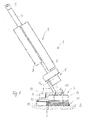
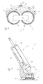
- a scouring-suction machine after the Fig. 1 to 16 represents a hand-held tillage implement in the context of the invention.
- the scouring-suction machine 1 is used for wet cleaning of floors in buildings.
- the scouring-suction machine 1 has a guide part 2 and a bottom part 3, which are connected to each other via a hinge assembly 9 described in more detail below.
- the guide part 2 is elongated and protrudes from the bottom part 3 from above.
- the guide part 2 comprises a central, dimensionally stable support tube 4, on the upper end region of which two handles 5 projecting to opposite sides are fastened. Between the handles 5 is a control block 22 (see Fig. 7 ), which is also firmly connected to the upper end face of the support tube 4.
- a suction drive 6 At a lower end portion of the support tube 4 is a suction drive 6 one below with reference to Fig. 5 attached suction system described in more detail.
- the suction drive 6 comprises an electrically operated suction turbine.
- the suction drive 6 forms the lower end of the guide part 2.
- the handles 5 with the control block 22 form the upper end of the guide part 2.
- a recovery tank 7 and a fresh water tank 8 are releasably attached. Both the dirty water tank 7 and the fresh water tank 8 are held by means of a quick-change system to the support tube 4 and can be removed without tools, replaced or attached to the support tube 4 again.
- the guide member 2 is pivotally connected via an upper hinge axis G 1 with the hinge assembly 9.
- the joint assembly 9 in turn is pivotally mounted by means of a lower hinge axis G 2 to the bottom part 3.
- the support tube 4 of the guide member 2 is coaxial with a vertical axis H 1 of the guide member 2 extends.
- the suction drive 6, which includes the electric suction turbine and a correspondingly dimensionally stable suction housing is fixed coaxially to the vertical axis H 1 at the lower end face of the support tube 4.
- the suction housing is a bearing component to which the hinge assembly 9 is articulated.
- the hinge assembly 9 comprises, as shown in FIG Fig. 2 can be seen, a dimensionally stable support web which is mounted pivotably about the lower hinge axis G 2 on the bottom part 3.
- the carrier web is connected via the upper joint axis G 1 pivotally connected to a support portion of the guide member 2, in particular with an extension of the support tube 4 or a support portion of the suction of the suction drive 6.
- the support web of the hinge assembly 9 extends in a plane parallel to a vertical axis H 1 receiving the pivot plane of the guide member 2, within which the guide member 2 according to Fig. 2 is mounted to pivot about the hinge axis G 1 on the support web of the joint assembly 9.
- the upper joint axis G 1 is aligned orthogonal to the vertical axis H 1 of the guide part 2.
- the lower joint axis G 2 is aligned orthogonal to the upper joint axis G 1 and orthogonal to the vertical axis H 1 , as long as the guide member 2 projects in a straight line extension to the support web of the hinge assembly 9 upwards.
- the hinge axis G 2 extends in the normal operating position of the bottom part 3 according to the Fig. 1 . 6, 7 parallel to a bottom B, on which the bottom part 3 rests in an operating position.
- Both the upper joint axis G 1 and the lower joint axis G 2 define pure pivot joints, each with two rotational degrees of freedom.
- the bottom part 3 is supported solely on the two tools 11 on the one hand and the Saugleistenan kann 12 on the other hand on the bottom B in the operating position of the scouring-suction machine 1. Since the guide member 2 is in turn supported on the bottom part 3 via the hinge assembly 9, the total weight of the scouring-suction machine 1 via a front support in the region of the support of the tools 11 on the bottom B and a rear support in the region of the support the sealing lips D supported on the bottom B.
- An attack region of the joint assembly 9 on the bottom part 3, by the lower hinge axis G 2 to the support bridge 10, is selected so as to provide a uniform weight distribution of the total weight of the scrubber-suction machine 1 on the front support in the area of the tools 11 and the rear support in the area of the squeegee assembly 12.
- a front-heavy weight distribution in the direction of the tools 11 can also be made.
- the scouring-suction machine 1 can be set up in a storage position, which defines a non-use position for the scouring-suction machine 1.
- the bottom part 3 is tilted over its front edge, which is defined by the leading edges of the rotatable tools 11, upwards.
- a support means in the form of a support roller 23 is arranged on which the bottom part 3 in the storage position according to Fig. 14 supported. The bottom part 3 is tilted so far that results in this storage position, a statically stable support on the front edge of the tools 11 on the one hand and the support roller 23 on the other hand.
- centrally arranged support roller 23 can also be provided a plurality of parallel spaced adjacent support rollers.
- the guide member 2 is pivoted for the non-use position corresponding storage position also relative to the erected bottom part 3 via a vertical out until securing means 25, 26 between the bottom part 3 and the guide member 2 to each other come into force fit.
- the guide part 2 is according to the embodiment Fig. 14 positioned in this position in an over-center position relative to the bottom part 3, so that the center of gravity of the guide part 2 is stably located above the bottom part 3.
- a permanent magnet 25 is provided on the guide part 2, which is assigned to the bottom part 3, a corresponding magnetizable surface 26.
- the permanent magnet 25 and the magnetizable surface 26 engage each other and cause a magnetic force limited securing the guide member 2 on the bottom part 3.
- the magnetic force protection can be easily by pivoting the guide member 2 to the Joint axis G 1 are repealed by the guide member 2 as shown in FIG Fig. 14 is orthogonally swung out of the plane. In this case, the mutually facing surfaces of the permanent magnet 25 and the magnetizable surface 26 slide laterally past each other. This movement is possible without much effort, since the magnetic force acts vertically between the adjacent surfaces of the magnetic security, but not parallel to this.
- the scouring-suction machine 1 in this in Fig. 14 illustrated securing position can also be transported in a simple manner by the scouring-suction machine 1 on the at least one support roller 23 manually tilted forward and then pulled or pushed over the handles 5.
- the scouring suction machine 1a after the FIGS. 17 and 18 basically has the same structure as the previously based on the Fig. 1 to 16 Scouring suction machine described in detail 1. Functionally identical parts and sections are provided with the same reference numerals with the addition of the letter a.
- the disclosure of the embodiment according to the Fig. 1 to 16 directed. Significant difference in the scouring-suction machine 1a after the FIGS.
- a single, cylindrical rotatable tool 11a is provided, which is mounted in the operating position of the scouring-suction machine 1a aligned parallel to the bottom B axis of rotation in the bottom part 3a.
- the tool 11a is provided with a single, not shown electric rotary drive.
- the tool 11a can be driven in only one direction of rotation, in which for the bottom part 3a a permanent propulsion in the direction of arrow (see FIGS. 17 and 18 ) is achieved.
- the direction of rotation of the tool 11a is in Fig. 17 also represented by a circular arc-shaped arrow.
- a fresh water supply takes place in the region of the tool 11a analogous to the scouring-suction machine 1 after the Fig. 1 to 16 ,
- the suction of the wastewater liquor is carried out in the same manner in the Saugleistenan Aunt 12a by means of the suction and sealing lips Da, as previously described.
Landscapes
- Cleaning In General (AREA)
- Soil Working Implements (AREA)
- Drying Of Solid Materials (AREA)
- Nozzles For Electric Vacuum Cleaners (AREA)
Priority Applications (3)
| Application Number | Priority Date | Filing Date | Title |
|---|---|---|---|
| DK16153985.3T DK3031378T3 (en) | 2013-08-02 | 2014-07-15 | HAND-GUIDED SOIL WORKING DEVICE |
| PL16153985T PL3031378T3 (pl) | 2013-08-02 | 2014-07-15 | Prowadzony ręcznie sprzęt do obróbki podłogi |
| EP16153985.3A EP3031378B1 (fr) | 2013-08-02 | 2014-07-15 | Appareil portatif de traitement des sols |
Applications Claiming Priority (1)
| Application Number | Priority Date | Filing Date | Title |
|---|---|---|---|
| DE201310215198 DE102013215198A1 (de) | 2013-08-02 | 2013-08-02 | Handgeführtes Bodenbearbeitungsgerät |
Related Child Applications (2)
| Application Number | Title | Priority Date | Filing Date |
|---|---|---|---|
| EP16153985.3A Division EP3031378B1 (fr) | 2013-08-02 | 2014-07-15 | Appareil portatif de traitement des sols |
| EP16153985.3A Division-Into EP3031378B1 (fr) | 2013-08-02 | 2014-07-15 | Appareil portatif de traitement des sols |
Publications (3)
| Publication Number | Publication Date |
|---|---|
| EP2832277A2 true EP2832277A2 (fr) | 2015-02-04 |
| EP2832277A3 EP2832277A3 (fr) | 2015-10-21 |
| EP2832277B1 EP2832277B1 (fr) | 2016-09-14 |
Family
ID=51205257
Family Applications (2)
| Application Number | Title | Priority Date | Filing Date |
|---|---|---|---|
| EP14177128.7A Active EP2832277B1 (fr) | 2013-08-02 | 2014-07-15 | Appareil portatif de traitement des sols |
| EP16153985.3A Active EP3031378B1 (fr) | 2013-08-02 | 2014-07-15 | Appareil portatif de traitement des sols |
Family Applications After (1)
| Application Number | Title | Priority Date | Filing Date |
|---|---|---|---|
| EP16153985.3A Active EP3031378B1 (fr) | 2013-08-02 | 2014-07-15 | Appareil portatif de traitement des sols |
Country Status (7)
| Country | Link |
|---|---|
| US (1) | US9826874B2 (fr) |
| EP (2) | EP2832277B1 (fr) |
| DE (2) | DE102013215198A1 (fr) |
| DK (2) | DK2832277T3 (fr) |
| ES (2) | ES2605395T3 (fr) |
| HU (2) | HUE030965T2 (fr) |
| PL (2) | PL2832277T3 (fr) |
Cited By (9)
| Publication number | Priority date | Publication date | Assignee | Title |
|---|---|---|---|---|
| DE102018207428B3 (de) | 2018-05-14 | 2019-05-23 | I-Mop Gmbh | Nassreinigungsvorrichtung zur Nassreinigung einer Bodenfläche |
| GB2573134A (en) * | 2018-04-25 | 2019-10-30 | Numatic Int Ltd | Floor treatment machine |
| GB2573161A (en) * | 2018-04-27 | 2019-10-30 | Numatic Int Ltd | Floor treatment machine |
| DE102018207435A1 (de) * | 2018-05-14 | 2019-11-14 | Hawig Maschinenfabrik Gesellschaft mit beschränkter Haftung | Nassreinigungsvorrichtung zur Nassreinigung einer Bodenfläche |
| DE102018207437A1 (de) * | 2018-05-14 | 2019-11-14 | Hawig Maschinenfabrik Gesellschaft mit beschränkter Haftung | Nassreinigungsvorrichtung zur Nassreinigung einer Bodenfläche |
| EP3597093A1 (fr) | 2018-06-29 | 2020-01-22 | Hawig Maschinenfabrik Gesellschaft mit beschränkter Haftung | Dispositif de nettoyage humide destiné au nettoyage humide d'une surface de plancher |
| WO2021028667A1 (fr) | 2019-08-09 | 2021-02-18 | Numatic International Limited | Machine de traitement de plancher |
| WO2022018216A1 (fr) * | 2020-07-22 | 2022-01-27 | I-Mop Gmbh | Dispositif de nettoyage de sols, en particulier dispositif de nettoyage de sols par frottement et aspiration, à propriétés de manœuvre améliorées |
| WO2022039591A1 (fr) * | 2020-08-17 | 2022-02-24 | Wensch Holding B.V. | Dispositif de nettoyage automoteur guidé par l'utilisateur |
Families Citing this family (45)
| Publication number | Priority date | Publication date | Assignee | Title |
|---|---|---|---|---|
| DE102015103500A1 (de) * | 2015-03-10 | 2016-09-15 | Industrialpartners Gmbh | Reinigungsgerät |
| DE102015104758A1 (de) * | 2015-03-27 | 2016-09-29 | Miele & Cie. Kg | Bodenreiniger |
| DE102016208895A1 (de) | 2016-05-23 | 2017-11-23 | Rudolf Franke | Bodenbearbeitungsmodul sowie Bodenbearbeitungsmaschine mit einem solchen Bodenbearbeitungsmodul |
| DE102017212873A1 (de) * | 2017-07-26 | 2019-01-31 | Hawig Maschinenfabrik Gesellschaft mit beschränkter Haftung | Flächenbearbeitungsgerät |
| IT201800002051A1 (it) | 2018-01-26 | 2019-07-26 | 4Cleanpro S R L | Apparecchiatura per il trattamento di pavimenti |
| WO2019157638A1 (fr) * | 2018-02-13 | 2019-08-22 | 深圳市赫兹科技有限公司 | Dispositif de nettoyage |
| DE202018105566U1 (de) * | 2018-02-13 | 2018-10-09 | Hizero Technologies Co., Ltd. | Reinigungsvorrichtung |
| CN108209708A (zh) * | 2018-02-27 | 2018-06-29 | 安吉艺科装饰材料科技有限公司 | 一种pvc地毯清洁装置 |
| CN116269038A (zh) | 2018-04-30 | 2023-06-23 | Lg电子株式会社 | 清洁器吸嘴 |
| WO2019212187A1 (fr) | 2018-04-30 | 2019-11-07 | 엘지전자 주식회사 | Buse d'appareil de nettoyage |
| KR102711296B1 (ko) | 2018-04-30 | 2024-09-30 | 엘지전자 주식회사 | 청소기의 노즐 |
| CN114504271B (zh) | 2018-04-30 | 2023-11-28 | Lg电子株式会社 | 清洁器 |
| WO2019212177A1 (fr) | 2018-04-30 | 2019-11-07 | 엘지전자 주식회사 | Buse d'aspirateur |
| KR102625905B1 (ko) | 2018-07-30 | 2024-01-18 | 엘지전자 주식회사 | 청소기의 노즐 |
| DE102018213565A1 (de) * | 2018-08-13 | 2020-02-13 | I-Mop Gmbh | Nassreinigungsvorrichtung zur Nassreinigung einer Bodenfläche |
| CN113573621B (zh) | 2018-12-21 | 2023-09-01 | 坦南特公司 | 能够处理大碎屑的清扫器/擦洗器系统 |
| DE102019109946A1 (de) | 2019-04-15 | 2020-10-15 | Alfred Kärcher SE & Co. KG | Reinigungsmaschine mit Gelenkeinrichtung und Reinigungsmaschine mit Antriebseinrichtung |
| IT201900007003A1 (it) | 2019-05-20 | 2020-11-20 | 4Cleanpro S R L | Apparecchiatura per il trattamento di pavimenti |
| CA3141296C (fr) * | 2019-05-21 | 2024-05-21 | Technological Systems By Moro S.R.L. | Dispositif pour nettoyage des surfaces pietonnes |
| NL2025598B1 (en) | 2020-05-18 | 2021-12-03 | Future Cleaning Tech B V | Scrubber-dryer system |
| US11771292B1 (en) | 2020-09-10 | 2023-10-03 | Karma 360, Inc. | Floor scrubber apparatus with releasably locking handle |
| HUE064302T2 (hu) * | 2020-10-06 | 2024-02-28 | Vermop Salmon Gmbh | Tisztítókészülék |
| ES3038264T3 (en) * | 2021-03-26 | 2025-10-10 | Dextron Tech Ltd | Surface treatment tool |
| CN117795212A (zh) | 2021-06-26 | 2024-03-29 | 坦南特公司 | 扭矩传递球接头 |
| DE102021119016A1 (de) | 2021-07-22 | 2023-01-26 | I-Mop Gmbh | Bodenreinigungsvorrichtung |
| GB2609221A (en) | 2021-07-23 | 2023-02-01 | Numatic Int Ltd | Hand guided floor treatment machine |
| DE212021000578U1 (de) | 2021-11-05 | 2024-05-06 | Numatic International Limited | Bodenbehandlungsmaschine |
| DE102022101563A1 (de) | 2022-01-24 | 2023-07-27 | I-Mop Gmbh | Bodenbearbeitungsvorrichtung, bevorzugt eine Bodenreinigungsvorrichtung, wie beispielsweise eine Scheuer-Bodenreinigungsvorrichtung |
| GB2615080A (en) | 2022-01-26 | 2023-08-02 | Numatic Int Ltd | Floor treatment machine |
| DE102022111720A1 (de) | 2022-05-10 | 2023-11-16 | Hako Gmbh | Handgeführte Bodenreinigungsmaschine mit einer Saugfußhalterung |
| DE102022207086A1 (de) * | 2022-07-12 | 2024-01-18 | BSH Hausgeräte GmbH | Bodenreiniger |
| CN115281568B (zh) * | 2022-08-10 | 2024-04-05 | 浙江金华科的科技有限公司 | 洗地机的推磨式连接机构以及洗地机 |
| DE102022121266A1 (de) | 2022-08-23 | 2024-02-29 | Hawig Maschinenfabrik Gesellschaft mit beschränkter Haftung | Ansaugschutzvorrichtung und Reinigungsvorrichtung mit einer solchen Ansaugschutzvorrichtung |
| GB2622398B (en) | 2022-09-14 | 2025-05-14 | Numatic Int Ltd | Floor treatment machine |
| NL2034313B1 (en) * | 2023-03-10 | 2024-09-24 | Wensch Holding B V | Cleaning device |
| WO2025133127A1 (fr) | 2023-12-21 | 2025-06-26 | I-Mop Gmbh | Système de traitement de surface |
| WO2025133130A1 (fr) | 2023-12-21 | 2025-06-26 | I-Mop Gmbh | Système de traitement de surface |
| WO2025168842A2 (fr) | 2024-02-09 | 2025-08-14 | I-Mop Gmbh | Appareil de nettoyage de surfaces, réservoir de fluide pour un appareil de nettoyage de surfaces, système de nettoyage de surfaces et procédé de nettoyage de surfaces |
| DE102024105885A1 (de) | 2024-02-29 | 2025-09-04 | Alfred Kärcher SE & Co. KG | Bodenreinigungsmaschine mit Parkposition, Verfahren zum Bringen einer Bodenreinigungsmaschine in eine Parkposition, und Verfahren zum Betreiben einer Bodenreinigungsmaschine |
| DE102024113194A1 (de) * | 2024-05-10 | 2025-11-13 | I-Mop Gmbh | Flächenreinigungsgerät |
| DE102024113192A1 (de) * | 2024-05-10 | 2025-11-13 | I-Mop Gmbh | Flächenreinigungskopf für ein Flächenreinigungsgerät |
| DE102024113189A1 (de) * | 2024-05-10 | 2025-11-13 | I-Mop Gmbh | Flächenreinigungsgerät |
| DE102024113193A1 (de) * | 2024-05-10 | 2025-11-13 | I-Mop Gmbh | Flächenreinigungskopf für ein Flächenreinigungsgerät |
| DE102024113191A1 (de) | 2024-05-10 | 2025-11-13 | I-Mop Gmbh | Flächenreinigungsgerät |
| NL2037675B1 (en) * | 2024-05-13 | 2025-11-25 | Wensch Holding B V | Scrubber-drier |
Citations (1)
| Publication number | Priority date | Publication date | Assignee | Title |
|---|---|---|---|---|
| WO2011023169A2 (fr) | 2009-08-27 | 2011-03-03 | Rainer Kenter | Appareil de traitement de sol à guidage manuel |
Family Cites Families (42)
| Publication number | Priority date | Publication date | Assignee | Title |
|---|---|---|---|---|
| US2558590A (en) * | 1946-08-20 | 1951-06-26 | Philip P Smith | Self-propelled manually steered portable rug-washing machine |
| FR1025236A (fr) * | 1949-10-17 | 1953-04-13 | Fraser Tuson Products Ltd | Perfectionnements aux machines servant à nettoyer, polir ou aplanir les parquets |
| US2818312A (en) * | 1955-03-10 | 1957-12-31 | Advance Machine Co | Selective handle connection for floor polishing machines |
| US3013287A (en) * | 1959-05-26 | 1961-12-19 | Electrolux Ab | Floor polisher |
| DE1205664B (de) * | 1960-08-02 | 1965-11-25 | Advance Machine Co | Maschine zum Bearbeiten und Pflegen von Fussboeden |
| DE2443969C3 (de) * | 1974-09-11 | 1980-06-26 | Herbert 1000 Berlin Schroeder | Gerät zur Vorbereitung der Reinigung von Teppichboden mit niedergetretenem Flor |
| US4334337A (en) * | 1980-03-28 | 1982-06-15 | Shop-Vac Corporation | Compact wet-dry electric vacuum cleaner |
| US4542556A (en) * | 1984-02-06 | 1985-09-24 | Hightec Manufacturing Corporation | Carpet vacuum, cleaning, and dyeing apparatus |
| US4577364A (en) | 1984-07-06 | 1986-03-25 | Demetriades Peter G | Floor cleaning machine |
| DE3540783A1 (de) | 1985-11-16 | 1987-05-21 | Hako Gmbh & Co | Fahrbare nassreinigungsmaschine |
| US4719659A (en) * | 1985-12-28 | 1988-01-19 | Uragami Fukashi | Rotary travelling surface treatment device |
| IT207992Z2 (it) | 1986-07-31 | 1988-03-14 | Idroplina Srl | Dispositivo a piu' spazzole per la pulizia di pavimenti e superfici. |
| DE8630341U1 (de) * | 1986-11-12 | 1987-01-08 | Hawig Maschinenfabrik Gmbh, 6140 Bensheim | Fußboden-Reinigungsmaschine |
| DE8700123U1 (de) * | 1987-01-03 | 1987-03-12 | FMA Metall- und Apparatebau GmbH, 6000 Frankfurt | Vorrichtung zur Reinigung von mit umweltbelastenden Substanzen verschmutzten Flächen und zur Entsorgung dieser Substanzen |
| DE3830847C2 (de) | 1988-09-10 | 1996-12-05 | Krahnen Gmbh | Fahrbares Bodenreinigungsgerät |
| US5237719A (en) * | 1991-10-17 | 1993-08-24 | Donald J. Dwyer, Sr. | Cleaning apparatus |
| DE4200064C2 (de) | 1992-01-03 | 1995-07-06 | Hako Gmbh & Co | Fahrbare Naßreinigungsmaschine |
| GB9315447D0 (en) | 1993-07-26 | 1993-09-08 | Unilever Plc | Floor cleaning and polishing equipment |
| DE29502611U1 (de) * | 1995-02-17 | 1995-06-14 | Grabietz, Gerhard, 48607 Ochtrup | Bürstenmobil |
| DE69608408T2 (de) | 1996-02-09 | 2000-09-21 | Unilever N.V., Rotterdam | Vorrichtung zum Bearbeiten einer Fläche mit einem rotierenden Element |
| US5765250A (en) | 1997-04-10 | 1998-06-16 | Lee; Kyu H. | Floor cleaner with tiltable handle and four wheel support for storage |
| DE19835185A1 (de) | 1998-08-04 | 2000-02-17 | Kenter Rainer | Vorrichtung zum Behandeln von Oberflächen |
| TW558430B (en) | 2000-11-01 | 2003-10-21 | Kao Corp | Cleaning device |
| US6588050B1 (en) | 2001-06-08 | 2003-07-08 | Michael D. Aiken | Floor cleaner |
| JP2006516423A (ja) * | 2003-01-10 | 2006-07-06 | ロイヤル アプライアンス マニュファクチュアリング カンパニー | 吸入式ウェット・ジェットモップ |
| US20040134016A1 (en) * | 2003-01-10 | 2004-07-15 | Royal Appliance Manufacturing Company | Suction wet jet mop |
| JP2006513833A (ja) | 2003-03-11 | 2006-04-27 | ザ プロクター アンド ギャンブル カンパニー | 洗浄器具 |
| DE10314379B4 (de) * | 2003-03-29 | 2007-04-19 | Fraunhofer-Gesellschaft zur Förderung der angewandten Forschung e.V. | Eigenfortbewegungsfähige Vorrichtung |
| US9125540B2 (en) * | 2006-03-10 | 2015-09-08 | Bissell Homecare, Inc. | Bare floor cleaner |
| DE102006033021A1 (de) | 2006-07-17 | 2008-01-24 | Vorwerk & Co. Interholding Gmbh | Elektro-Staubsauger mit einem Grundgerät und einem Vorsatzgerät |
| US8051530B2 (en) * | 2006-11-17 | 2011-11-08 | Tennant Company | Squeegee assembly and method of using same |
| DE102007010303A1 (de) | 2007-02-22 | 2008-08-28 | Flex-Elektrowerkzeuge Gmbh | Handgehaltene Reinigungs-/Schleifmaschine |
| JP4884258B2 (ja) | 2007-02-27 | 2012-02-29 | アマノ株式会社 | 床面洗浄清掃機 |
| DE102007029258A1 (de) | 2007-06-15 | 2008-12-18 | Alfred Kärcher Gmbh & Co. Kg | Bodenreinigungsgerät |
| US8282445B2 (en) | 2007-07-20 | 2012-10-09 | Onfloor Technologies, L.L.C. | Floor finishing apparatus |
| IT1391610B1 (it) * | 2008-11-05 | 2012-01-11 | Ip Cleaning S P A | Lavapavimenti |
| US9357897B2 (en) * | 2009-02-28 | 2016-06-07 | Brent McNair Estep | Hands-free pot scrubber |
| US8444157B2 (en) * | 2009-04-06 | 2013-05-21 | Mark Pryor | Wheel set attachment for floor maintenance equipment |
| WO2011071506A1 (fr) | 2009-12-11 | 2011-06-16 | Hruby Orbital Systems, Inc. | Appareil de nettoyage de surface orbital |
| DK2598012T3 (da) | 2010-07-27 | 2014-07-21 | Kaercher Gmbh & Co Kg Alfred | Gulvbehandlingsindretning med forrådsbeholdersikring |
| AU2011244927B2 (en) * | 2010-11-05 | 2014-10-09 | Bissell Inc. | Bare floor vacuum cleaner |
| US9402523B2 (en) * | 2011-03-14 | 2016-08-02 | Roy Studebaker | Rotary surface cleaning tool |
-
2013
- 2013-08-02 DE DE201310215198 patent/DE102013215198A1/de active Pending
- 2013-08-02 DE DE202013012528.4U patent/DE202013012528U1/de not_active Expired - Lifetime
-
2014
- 2014-07-15 PL PL14177128T patent/PL2832277T3/pl unknown
- 2014-07-15 DK DK14177128.7T patent/DK2832277T3/da active
- 2014-07-15 DK DK16153985.3T patent/DK3031378T3/en active
- 2014-07-15 HU HUE14177128A patent/HUE030965T2/en unknown
- 2014-07-15 HU HUE16153985A patent/HUE034303T2/en unknown
- 2014-07-15 PL PL16153985T patent/PL3031378T3/pl unknown
- 2014-07-15 EP EP14177128.7A patent/EP2832277B1/fr active Active
- 2014-07-15 EP EP16153985.3A patent/EP3031378B1/fr active Active
- 2014-07-15 ES ES14177128.7T patent/ES2605395T3/es active Active
- 2014-07-15 ES ES16153985.3T patent/ES2640742T3/es active Active
- 2014-07-31 US US14/448,570 patent/US9826874B2/en active Active
Patent Citations (1)
| Publication number | Priority date | Publication date | Assignee | Title |
|---|---|---|---|---|
| WO2011023169A2 (fr) | 2009-08-27 | 2011-03-03 | Rainer Kenter | Appareil de traitement de sol à guidage manuel |
Cited By (24)
| Publication number | Priority date | Publication date | Assignee | Title |
|---|---|---|---|---|
| GB2573134B (en) * | 2018-04-25 | 2022-04-27 | Numatic Int Ltd | Floor scrubber dryer |
| WO2019207290A3 (fr) * | 2018-04-25 | 2019-12-19 | Numatic International Limited | Machine de traitement des sols |
| US12465185B2 (en) * | 2018-04-25 | 2025-11-11 | Numatic International Limited | Floor treatment machine |
| CN112739246A (zh) * | 2018-04-25 | 2021-04-30 | 纽麦蒂克国际有限公司 | 地板处理机器 |
| US20210267427A1 (en) * | 2018-04-25 | 2021-09-02 | Numatic International Limited | Floor treatment machine |
| GB2573134A (en) * | 2018-04-25 | 2019-10-30 | Numatic Int Ltd | Floor treatment machine |
| GB2573161A (en) * | 2018-04-27 | 2019-10-30 | Numatic Int Ltd | Floor treatment machine |
| GB2573161B (en) * | 2018-04-27 | 2022-08-24 | Numatic Int Ltd | Floor treatment machine |
| WO2019219580A1 (fr) | 2018-05-14 | 2019-11-21 | Hawig Maschinenfabrik Gesellschaft mit beschränkter Haftung | Dispositif de nettoyage humide pour le nettoyage humide d'un sol |
| DE102018207428B3 (de) | 2018-05-14 | 2019-05-23 | I-Mop Gmbh | Nassreinigungsvorrichtung zur Nassreinigung einer Bodenfläche |
| WO2019219582A1 (fr) | 2018-05-14 | 2019-11-21 | Hawig Maschinenfabrik Gesellschaft mit beschränkter Haftung | Dispositif de nettoyage humide pour le nettoyage humide d'un sol |
| DE102018207435A1 (de) * | 2018-05-14 | 2019-11-14 | Hawig Maschinenfabrik Gesellschaft mit beschränkter Haftung | Nassreinigungsvorrichtung zur Nassreinigung einer Bodenfläche |
| US11297993B2 (en) | 2018-05-14 | 2022-04-12 | I-Mop Gmbh | Wet-cleaning apparatus for the wet cleaning of a floor surface |
| DE102018207437A1 (de) * | 2018-05-14 | 2019-11-14 | Hawig Maschinenfabrik Gesellschaft mit beschränkter Haftung | Nassreinigungsvorrichtung zur Nassreinigung einer Bodenfläche |
| EP3569128A3 (fr) * | 2018-05-14 | 2019-12-11 | i-mop GmbH | Dispositif de nettoyage humide destiné au nettoyage humide d'une surface de plancher |
| EP3569128A2 (fr) | 2018-05-14 | 2019-11-20 | i-mop GmbH | Dispositif de nettoyage humide destiné au nettoyage humide d'une surface de plancher |
| EP3597093A1 (fr) | 2018-06-29 | 2020-01-22 | Hawig Maschinenfabrik Gesellschaft mit beschränkter Haftung | Dispositif de nettoyage humide destiné au nettoyage humide d'une surface de plancher |
| CN114423322A (zh) * | 2019-08-09 | 2022-04-29 | 纽麦蒂克国际有限公司 | 地板处理机 |
| WO2021028667A1 (fr) | 2019-08-09 | 2021-02-18 | Numatic International Limited | Machine de traitement de plancher |
| CN114423322B (zh) * | 2019-08-09 | 2023-10-13 | 纽麦蒂克国际有限公司 | 地板处理机 |
| US12433464B2 (en) | 2019-08-09 | 2025-10-07 | Numatic International Limited | Floor treatment machine |
| WO2022018216A1 (fr) * | 2020-07-22 | 2022-01-27 | I-Mop Gmbh | Dispositif de nettoyage de sols, en particulier dispositif de nettoyage de sols par frottement et aspiration, à propriétés de manœuvre améliorées |
| WO2022039591A1 (fr) * | 2020-08-17 | 2022-02-24 | Wensch Holding B.V. | Dispositif de nettoyage automoteur guidé par l'utilisateur |
| NL2026276B1 (en) * | 2020-08-17 | 2022-04-14 | Wensch Holding B V | Self-propelled cleaning device |
Also Published As
| Publication number | Publication date |
|---|---|
| DE202013012528U9 (de) | 2017-08-10 |
| EP3031378A1 (fr) | 2016-06-15 |
| DK2832277T3 (da) | 2017-01-02 |
| HUE034303T2 (en) | 2018-02-28 |
| PL2832277T3 (pl) | 2017-02-28 |
| DE202013012528U1 (de) | 2017-04-20 |
| US9826874B2 (en) | 2017-11-28 |
| ES2640742T3 (es) | 2017-11-06 |
| EP2832277A3 (fr) | 2015-10-21 |
| ES2605395T3 (es) | 2017-03-14 |
| DK3031378T3 (en) | 2017-09-25 |
| PL3031378T3 (pl) | 2017-12-29 |
| HUE030965T2 (en) | 2017-06-28 |
| EP2832277B1 (fr) | 2016-09-14 |
| EP3031378B1 (fr) | 2017-06-28 |
| DE102013215198A1 (de) | 2015-02-05 |
| US20150113757A1 (en) | 2015-04-30 |
Similar Documents
| Publication | Publication Date | Title |
|---|---|---|
| EP2832277B1 (fr) | Appareil portatif de traitement des sols | |
| EP3033984B1 (fr) | Appareil de traitement de sol a guidage manuel | |
| EP2147625B1 (fr) | Appareil de nettoyage | |
| EP0154169B1 (fr) | Dispositif de nettoyage pour armes à canon | |
| EP2773254B1 (fr) | Machine d'entretien du sol poussèe a man | |
| DE102016208895A1 (de) | Bodenbearbeitungsmodul sowie Bodenbearbeitungsmaschine mit einem solchen Bodenbearbeitungsmodul | |
| DE102014114776A1 (de) | Flächen-Reinigungsmaschine | |
| EP1949836B1 (fr) | Dispositif de nettoyage | |
| DE60006401T2 (de) | Antriebsvorrichtung für flexible lanze | |
| EP2773253A1 (fr) | Machine de nettoyage des sols guidée à la main | |
| DE102023136194A1 (de) | Flächenbehandlungssystem | |
| DE102023136195A1 (de) | Flächenbehandlungssystem | |
| DE202015106518U1 (de) | Bodenbearbeitungsgerät | |
| DE102013022770B4 (de) | Handgeführtes Bodenbearbeitungsgerät | |
| DE2734266C3 (de) | Fahrbares Gerät zum Verlegen von biegsamen Rohren oder Kabeln | |
| DE3309967A1 (de) | Bodenreinigungsmaschine | |
| DE102020115704B4 (de) | Einachsige vorrichtung | |
| DE102016103235A1 (de) | Vorschubeinrichtung für eine reinigungsvorrichtung | |
| DE8701171U1 (de) | Frontanbaugerät für ein Straßenreinigungskraftfahrzeug o.dgl. | |
| DE614389C (de) | Kantvorrichtung fuer Walzwerke | |
| DE102009027472A1 (de) | Handfräser | |
| AT508583A1 (de) | Holzspalter | |
| DE4413278A1 (de) | Windkraftanlage mit einem Mast, der nach Maßgabe der Windgeschwindigkeit auf unterschiedliche Masthöhe ein- und ausfahrbar ist | |
| DE2359643C3 (de) | Straßenkehrmaschine | |
| DE202012010452U1 (de) | Bodenreinigungsvorrichtung |
Legal Events
| Date | Code | Title | Description |
|---|---|---|---|
| 17P | Request for examination filed |
Effective date: 20140715 |
|
| AK | Designated contracting states |
Kind code of ref document: A2 Designated state(s): AL AT BE BG CH CY CZ DE DK EE ES FI FR GB GR HR HU IE IS IT LI LT LU LV MC MK MT NL NO PL PT RO RS SE SI SK SM TR |
|
| AX | Request for extension of the european patent |
Extension state: BA ME |
|
| PUAI | Public reference made under article 153(3) epc to a published international application that has entered the european phase |
Free format text: ORIGINAL CODE: 0009012 |
|
| PUAL | Search report despatched |
Free format text: ORIGINAL CODE: 0009013 |
|
| AK | Designated contracting states |
Kind code of ref document: A3 Designated state(s): AL AT BE BG CH CY CZ DE DK EE ES FI FR GB GR HR HU IE IS IT LI LT LU LV MC MK MT NL NO PL PT RO RS SE SI SK SM TR |
|
| AX | Request for extension of the european patent |
Extension state: BA ME |
|
| RIC1 | Information provided on ipc code assigned before grant |
Ipc: A47L 11/30 20060101AFI20150917BHEP Ipc: A47L 11/40 20060101ALI20150917BHEP Ipc: A47L 11/26 20060101ALI20150917BHEP |
|
| R17P | Request for examination filed (corrected) |
Effective date: 20151126 |
|
| RBV | Designated contracting states (corrected) |
Designated state(s): AL AT BE BG CH CY CZ DE DK EE ES FI FR GB GR HR HU IE IS IT LI LT LU LV MC MK MT NL NO PL PT RO RS SE SI SK SM TR |
|
| GRAP | Despatch of communication of intention to grant a patent |
Free format text: ORIGINAL CODE: EPIDOSNIGR1 |
|
| INTG | Intention to grant announced |
Effective date: 20160415 |
|
| GRAS | Grant fee paid |
Free format text: ORIGINAL CODE: EPIDOSNIGR3 |
|
| GRAA | (expected) grant |
Free format text: ORIGINAL CODE: 0009210 |
|
| AK | Designated contracting states |
Kind code of ref document: B1 Designated state(s): AL AT BE BG CH CY CZ DE DK EE ES FI FR GB GR HR HU IE IS IT LI LT LU LV MC MK MT NL NO PL PT RO RS SE SI SK SM TR |
|
| REG | Reference to a national code |
Ref country code: GB Ref legal event code: FG4D Free format text: NOT ENGLISH |
|
| REG | Reference to a national code |
Ref country code: CH Ref legal event code: EP |
|
| REG | Reference to a national code |
Ref country code: IE Ref legal event code: FG4D Free format text: LANGUAGE OF EP DOCUMENT: GERMAN |
|
| REG | Reference to a national code |
Ref country code: AT Ref legal event code: REF Ref document number: 827980 Country of ref document: AT Kind code of ref document: T Effective date: 20161015 |
|
| REG | Reference to a national code |
Ref country code: DE Ref legal event code: R096 Ref document number: 502014001438 Country of ref document: DE |
|
| REG | Reference to a national code |
Ref country code: NL Ref legal event code: FP |
|
| REG | Reference to a national code |
Ref country code: SE Ref legal event code: TRGR |
|
| REG | Reference to a national code |
Ref country code: CH Ref legal event code: NV Representative=s name: DR. LUSUARDI AG, CH |
|
| REG | Reference to a national code |
Ref country code: DK Ref legal event code: T3 Effective date: 20161222 |
|
| REG | Reference to a national code |
Ref country code: LT Ref legal event code: MG4D |
|
| PG25 | Lapsed in a contracting state [announced via postgrant information from national office to epo] |
Ref country code: NO Free format text: LAPSE BECAUSE OF FAILURE TO SUBMIT A TRANSLATION OF THE DESCRIPTION OR TO PAY THE FEE WITHIN THE PRESCRIBED TIME-LIMIT Effective date: 20161214 Ref country code: HR Free format text: LAPSE BECAUSE OF FAILURE TO SUBMIT A TRANSLATION OF THE DESCRIPTION OR TO PAY THE FEE WITHIN THE PRESCRIBED TIME-LIMIT Effective date: 20160914 Ref country code: FI Free format text: LAPSE BECAUSE OF FAILURE TO SUBMIT A TRANSLATION OF THE DESCRIPTION OR TO PAY THE FEE WITHIN THE PRESCRIBED TIME-LIMIT Effective date: 20160914 Ref country code: RS Free format text: LAPSE BECAUSE OF FAILURE TO SUBMIT A TRANSLATION OF THE DESCRIPTION OR TO PAY THE FEE WITHIN THE PRESCRIBED TIME-LIMIT Effective date: 20160914 Ref country code: LT Free format text: LAPSE BECAUSE OF FAILURE TO SUBMIT A TRANSLATION OF THE DESCRIPTION OR TO PAY THE FEE WITHIN THE PRESCRIBED TIME-LIMIT Effective date: 20160914 |
|
| PG25 | Lapsed in a contracting state [announced via postgrant information from national office to epo] |
Ref country code: LV Free format text: LAPSE BECAUSE OF FAILURE TO SUBMIT A TRANSLATION OF THE DESCRIPTION OR TO PAY THE FEE WITHIN THE PRESCRIBED TIME-LIMIT Effective date: 20160914 Ref country code: GR Free format text: LAPSE BECAUSE OF FAILURE TO SUBMIT A TRANSLATION OF THE DESCRIPTION OR TO PAY THE FEE WITHIN THE PRESCRIBED TIME-LIMIT Effective date: 20161215 |
|
| REG | Reference to a national code |
Ref country code: ES Ref legal event code: FG2A Ref document number: 2605395 Country of ref document: ES Kind code of ref document: T3 Effective date: 20170314 |
|
| PG25 | Lapsed in a contracting state [announced via postgrant information from national office to epo] |
Ref country code: EE Free format text: LAPSE BECAUSE OF FAILURE TO SUBMIT A TRANSLATION OF THE DESCRIPTION OR TO PAY THE FEE WITHIN THE PRESCRIBED TIME-LIMIT Effective date: 20160914 Ref country code: RO Free format text: LAPSE BECAUSE OF FAILURE TO SUBMIT A TRANSLATION OF THE DESCRIPTION OR TO PAY THE FEE WITHIN THE PRESCRIBED TIME-LIMIT Effective date: 20160914 |
|
| PG25 | Lapsed in a contracting state [announced via postgrant information from national office to epo] |
Ref country code: SM Free format text: LAPSE BECAUSE OF FAILURE TO SUBMIT A TRANSLATION OF THE DESCRIPTION OR TO PAY THE FEE WITHIN THE PRESCRIBED TIME-LIMIT Effective date: 20160914 Ref country code: CZ Free format text: LAPSE BECAUSE OF FAILURE TO SUBMIT A TRANSLATION OF THE DESCRIPTION OR TO PAY THE FEE WITHIN THE PRESCRIBED TIME-LIMIT Effective date: 20160914 Ref country code: PT Free format text: LAPSE BECAUSE OF FAILURE TO SUBMIT A TRANSLATION OF THE DESCRIPTION OR TO PAY THE FEE WITHIN THE PRESCRIBED TIME-LIMIT Effective date: 20170116 Ref country code: IS Free format text: LAPSE BECAUSE OF FAILURE TO SUBMIT A TRANSLATION OF THE DESCRIPTION OR TO PAY THE FEE WITHIN THE PRESCRIBED TIME-LIMIT Effective date: 20170114 Ref country code: BG Free format text: LAPSE BECAUSE OF FAILURE TO SUBMIT A TRANSLATION OF THE DESCRIPTION OR TO PAY THE FEE WITHIN THE PRESCRIBED TIME-LIMIT Effective date: 20161214 Ref country code: SK Free format text: LAPSE BECAUSE OF FAILURE TO SUBMIT A TRANSLATION OF THE DESCRIPTION OR TO PAY THE FEE WITHIN THE PRESCRIBED TIME-LIMIT Effective date: 20160914 |
|
| REG | Reference to a national code |
Ref country code: DE Ref legal event code: R026 Ref document number: 502014001438 Country of ref document: DE |
|
| PLBI | Opposition filed |
Free format text: ORIGINAL CODE: 0009260 |
|
| REG | Reference to a national code |
Ref country code: HU Ref legal event code: AG4A Ref document number: E030965 Country of ref document: HU |
|
| PLAX | Notice of opposition and request to file observation + time limit sent |
Free format text: ORIGINAL CODE: EPIDOSNOBS2 |
|
| 26 | Opposition filed |
Opponent name: ALFRED KAERCHER GMBH & CO. KG Effective date: 20170614 |
|
| REG | Reference to a national code |
Ref country code: FR Ref legal event code: PLFP Year of fee payment: 4 |
|
| PLBB | Reply of patent proprietor to notice(s) of opposition received |
Free format text: ORIGINAL CODE: EPIDOSNOBS3 |
|
| PG25 | Lapsed in a contracting state [announced via postgrant information from national office to epo] |
Ref country code: SI Free format text: LAPSE BECAUSE OF FAILURE TO SUBMIT A TRANSLATION OF THE DESCRIPTION OR TO PAY THE FEE WITHIN THE PRESCRIBED TIME-LIMIT Effective date: 20160914 |
|
| REG | Reference to a national code |
Ref country code: IE Ref legal event code: MM4A |
|
| PG25 | Lapsed in a contracting state [announced via postgrant information from national office to epo] |
Ref country code: IE Free format text: LAPSE BECAUSE OF NON-PAYMENT OF DUE FEES Effective date: 20170715 |
|
| REG | Reference to a national code |
Ref country code: BE Ref legal event code: MM Effective date: 20170731 |
|
| PG25 | Lapsed in a contracting state [announced via postgrant information from national office to epo] |
Ref country code: LU Free format text: LAPSE BECAUSE OF NON-PAYMENT OF DUE FEES Effective date: 20170715 |
|
| REG | Reference to a national code |
Ref country code: FR Ref legal event code: PLFP Year of fee payment: 5 |
|
| PLAB | Opposition data, opponent's data or that of the opponent's representative modified |
Free format text: ORIGINAL CODE: 0009299OPPO |
|
| R26 | Opposition filed (corrected) |
Opponent name: ALFRED KAERCHER SE CO. KG Effective date: 20170614 |
|
| PG25 | Lapsed in a contracting state [announced via postgrant information from national office to epo] |
Ref country code: BE Free format text: LAPSE BECAUSE OF NON-PAYMENT OF DUE FEES Effective date: 20170731 |
|
| PG25 | Lapsed in a contracting state [announced via postgrant information from national office to epo] |
Ref country code: MT Free format text: LAPSE BECAUSE OF FAILURE TO SUBMIT A TRANSLATION OF THE DESCRIPTION OR TO PAY THE FEE WITHIN THE PRESCRIBED TIME-LIMIT Effective date: 20160914 |
|
| PG25 | Lapsed in a contracting state [announced via postgrant information from national office to epo] |
Ref country code: AL Free format text: LAPSE BECAUSE OF FAILURE TO SUBMIT A TRANSLATION OF THE DESCRIPTION OR TO PAY THE FEE WITHIN THE PRESCRIBED TIME-LIMIT Effective date: 20160914 |
|
| PLCK | Communication despatched that opposition was rejected |
Free format text: ORIGINAL CODE: EPIDOSNREJ1 |
|
| STAA | Information on the status of an ep patent application or granted ep patent |
Free format text: STATUS: THE PATENT HAS BEEN GRANTED |
|
| APAH | Appeal reference modified |
Free format text: ORIGINAL CODE: EPIDOSCREFNO |
|
| APBM | Appeal reference recorded |
Free format text: ORIGINAL CODE: EPIDOSNREFNO |
|
| APBP | Date of receipt of notice of appeal recorded |
Free format text: ORIGINAL CODE: EPIDOSNNOA2O |
|
| APBQ | Date of receipt of statement of grounds of appeal recorded |
Free format text: ORIGINAL CODE: EPIDOSNNOA3O |
|
| PG25 | Lapsed in a contracting state [announced via postgrant information from national office to epo] |
Ref country code: MC Free format text: LAPSE BECAUSE OF FAILURE TO SUBMIT A TRANSLATION OF THE DESCRIPTION OR TO PAY THE FEE WITHIN THE PRESCRIBED TIME-LIMIT Effective date: 20160914 |
|
| PG25 | Lapsed in a contracting state [announced via postgrant information from national office to epo] |
Ref country code: CY Free format text: LAPSE BECAUSE OF FAILURE TO SUBMIT A TRANSLATION OF THE DESCRIPTION OR TO PAY THE FEE WITHIN THE PRESCRIBED TIME-LIMIT Effective date: 20160914 |
|
| PG25 | Lapsed in a contracting state [announced via postgrant information from national office to epo] |
Ref country code: MK Free format text: LAPSE BECAUSE OF FAILURE TO SUBMIT A TRANSLATION OF THE DESCRIPTION OR TO PAY THE FEE WITHIN THE PRESCRIBED TIME-LIMIT Effective date: 20160914 |
|
| REG | Reference to a national code |
Ref country code: AT Ref legal event code: MM01 Ref document number: 827980 Country of ref document: AT Kind code of ref document: T Effective date: 20190715 |
|
| PG25 | Lapsed in a contracting state [announced via postgrant information from national office to epo] |
Ref country code: AT Free format text: LAPSE BECAUSE OF NON-PAYMENT OF DUE FEES Effective date: 20190715 |
|
| APBY | Invitation to file observations in appeal sent |
Free format text: ORIGINAL CODE: EPIDOSNOBA2O |
|
| APCA | Receipt of observations in appeal recorded |
Free format text: ORIGINAL CODE: EPIDOSNOBA4O |
|
| REG | Reference to a national code |
Ref country code: DE Ref legal event code: R100 Ref document number: 502014001438 Country of ref document: DE |
|
| APBU | Appeal procedure closed |
Free format text: ORIGINAL CODE: EPIDOSNNOA9O |
|
| PLBN | Opposition rejected |
Free format text: ORIGINAL CODE: 0009273 |
|
| STAA | Information on the status of an ep patent application or granted ep patent |
Free format text: STATUS: OPPOSITION REJECTED |
|
| 27O | Opposition rejected |
Effective date: 20220214 |
|
| P01 | Opt-out of the competence of the unified patent court (upc) registered |
Effective date: 20230519 |
|
| REG | Reference to a national code |
Ref country code: DE Ref legal event code: R039 Ref document number: 502014001438 Country of ref document: DE Ref country code: DE Ref legal event code: R008 Ref document number: 502014001438 Country of ref document: DE |
|
| REG | Reference to a national code |
Ref country code: ES Ref legal event code: GD2A Effective date: 20240611 |
|
| PGFP | Annual fee paid to national office [announced via postgrant information from national office to epo] |
Ref country code: PL Payment date: 20250617 Year of fee payment: 12 |
|
| PGFP | Annual fee paid to national office [announced via postgrant information from national office to epo] |
Ref country code: NL Payment date: 20250723 Year of fee payment: 12 |
|
| PGFP | Annual fee paid to national office [announced via postgrant information from national office to epo] |
Ref country code: HU Payment date: 20250711 Year of fee payment: 12 |
|
| PGFP | Annual fee paid to national office [announced via postgrant information from national office to epo] |
Ref country code: ES Payment date: 20250819 Year of fee payment: 12 |
|
| PGFP | Annual fee paid to national office [announced via postgrant information from national office to epo] |
Ref country code: DE Payment date: 20250723 Year of fee payment: 12 Ref country code: DK Payment date: 20250723 Year of fee payment: 12 |
|
| PGFP | Annual fee paid to national office [announced via postgrant information from national office to epo] |
Ref country code: TR Payment date: 20250709 Year of fee payment: 12 Ref country code: IT Payment date: 20250731 Year of fee payment: 12 |
|
| PGFP | Annual fee paid to national office [announced via postgrant information from national office to epo] |
Ref country code: GB Payment date: 20250724 Year of fee payment: 12 |
|
| PGFP | Annual fee paid to national office [announced via postgrant information from national office to epo] |
Ref country code: FR Payment date: 20250723 Year of fee payment: 12 |
|
| PGFP | Annual fee paid to national office [announced via postgrant information from national office to epo] |
Ref country code: SE Payment date: 20250723 Year of fee payment: 12 Ref country code: CH Payment date: 20250801 Year of fee payment: 12 |
|
| REG | Reference to a national code |
Ref country code: DE Ref legal event code: R040 Ref document number: 502014001438 Country of ref document: DE |