EP3569989A1 - Compteur de fluide - Google Patents
Compteur de fluide Download PDFInfo
- Publication number
- EP3569989A1 EP3569989A1 EP19170992.2A EP19170992A EP3569989A1 EP 3569989 A1 EP3569989 A1 EP 3569989A1 EP 19170992 A EP19170992 A EP 19170992A EP 3569989 A1 EP3569989 A1 EP 3569989A1
- Authority
- EP
- European Patent Office
- Prior art keywords
- temperature
- fluid
- fluid meter
- flow
- meter
- Prior art date
- Legal status (The legal status is an assumption and is not a legal conclusion. Google has not performed a legal analysis and makes no representation as to the accuracy of the status listed.)
- Granted
Links
Images

Classifications
-
- G—PHYSICS
- G01—MEASURING; TESTING
- G01F—MEASURING VOLUME, VOLUME FLOW, MASS FLOW OR LIQUID LEVEL; METERING BY VOLUME
- G01F1/00—Measuring the volume flow or mass flow of fluid or fluent solid material wherein the fluid passes through a meter in a continuous flow
- G01F1/66—Measuring the volume flow or mass flow of fluid or fluent solid material wherein the fluid passes through a meter in a continuous flow by measuring frequency, phase shift or propagation time of electromagnetic or other waves, e.g. using ultrasonic flowmeters
-
- G—PHYSICS
- G01—MEASURING; TESTING
- G01F—MEASURING VOLUME, VOLUME FLOW, MASS FLOW OR LIQUID LEVEL; METERING BY VOLUME
- G01F1/00—Measuring the volume flow or mass flow of fluid or fluent solid material wherein the fluid passes through a meter in a continuous flow
- G01F1/66—Measuring the volume flow or mass flow of fluid or fluent solid material wherein the fluid passes through a meter in a continuous flow by measuring frequency, phase shift or propagation time of electromagnetic or other waves, e.g. using ultrasonic flowmeters
- G01F1/662—Constructional details
-
- G—PHYSICS
- G01—MEASURING; TESTING
- G01F—MEASURING VOLUME, VOLUME FLOW, MASS FLOW OR LIQUID LEVEL; METERING BY VOLUME
- G01F1/00—Measuring the volume flow or mass flow of fluid or fluent solid material wherein the fluid passes through a meter in a continuous flow
- G01F1/66—Measuring the volume flow or mass flow of fluid or fluent solid material wherein the fluid passes through a meter in a continuous flow by measuring frequency, phase shift or propagation time of electromagnetic or other waves, e.g. using ultrasonic flowmeters
- G01F1/665—Measuring the volume flow or mass flow of fluid or fluent solid material wherein the fluid passes through a meter in a continuous flow by measuring frequency, phase shift or propagation time of electromagnetic or other waves, e.g. using ultrasonic flowmeters of the drag-type
-
- G—PHYSICS
- G01—MEASURING; TESTING
- G01F—MEASURING VOLUME, VOLUME FLOW, MASS FLOW OR LIQUID LEVEL; METERING BY VOLUME
- G01F1/00—Measuring the volume flow or mass flow of fluid or fluent solid material wherein the fluid passes through a meter in a continuous flow
- G01F1/68—Measuring the volume flow or mass flow of fluid or fluent solid material wherein the fluid passes through a meter in a continuous flow by using thermal effects
- G01F1/684—Structural arrangements; Mounting of elements, e.g. in relation to fluid flow
-
- G—PHYSICS
- G01—MEASURING; TESTING
- G01K—MEASURING TEMPERATURE; MEASURING QUANTITY OF HEAT; THERMALLY-SENSITIVE ELEMENTS NOT OTHERWISE PROVIDED FOR
- G01K1/00—Details of thermometers not specially adapted for particular types of thermometer
- G01K1/14—Supports; Fastening devices; Arrangements for mounting thermometers in particular locations
-
- G—PHYSICS
- G01—MEASURING; TESTING
- G01K—MEASURING TEMPERATURE; MEASURING QUANTITY OF HEAT; THERMALLY-SENSITIVE ELEMENTS NOT OTHERWISE PROVIDED FOR
- G01K17/00—Measuring quantity of heat
- G01K17/06—Measuring quantity of heat conveyed by flowing media, e.g. in heating systems e.g. the quantity of heat in a transporting medium, delivered to or consumed in an expenditure device
- G01K17/08—Measuring quantity of heat conveyed by flowing media, e.g. in heating systems e.g. the quantity of heat in a transporting medium, delivered to or consumed in an expenditure device based upon measurement of temperature difference or of a temperature
- G01K17/10—Measuring quantity of heat conveyed by flowing media, e.g. in heating systems e.g. the quantity of heat in a transporting medium, delivered to or consumed in an expenditure device based upon measurement of temperature difference or of a temperature between an inlet and an outlet point, combined with measurement of rate of flow of the medium if such, by integration during a certain time-interval
-
- G—PHYSICS
- G01—MEASURING; TESTING
- G01K—MEASURING TEMPERATURE; MEASURING QUANTITY OF HEAT; THERMALLY-SENSITIVE ELEMENTS NOT OTHERWISE PROVIDED FOR
- G01K17/00—Measuring quantity of heat
- G01K17/06—Measuring quantity of heat conveyed by flowing media, e.g. in heating systems e.g. the quantity of heat in a transporting medium, delivered to or consumed in an expenditure device
- G01K17/08—Measuring quantity of heat conveyed by flowing media, e.g. in heating systems e.g. the quantity of heat in a transporting medium, delivered to or consumed in an expenditure device based upon measurement of temperature difference or of a temperature
- G01K17/10—Measuring quantity of heat conveyed by flowing media, e.g. in heating systems e.g. the quantity of heat in a transporting medium, delivered to or consumed in an expenditure device based upon measurement of temperature difference or of a temperature between an inlet and an outlet point, combined with measurement of rate of flow of the medium if such, by integration during a certain time-interval
- G01K17/12—Indicating product of flow and temperature difference directly or temperature
Definitions
- the present invention relates to a fluid meter, in particular a heat meter for detecting the amount of cold and / or heat of a fluid, according to claim 1 and a method for operating a fluid meter.
- Generic fluid meters are measuring devices for determining the flow rate of a fluid such. As water meter, gas meter, heat meter or the like. Such fluid meters or flow sensors are usually installed in a fluid line system.
- a generic réellemengenzäher serves to determine the energy in the form of a heat or cold amount, which z.
- B a consumer supplied via a heating circuit or removed via a heat exchanger with a cooling circuit. The energy or heat energy is determined from the volume flow of the fluid and the temperature difference between the temperature in the flow (that is, in the direction of flow of the fluid before the consumer) and the temperature in the return (i.e., in the flow direction of the fluid after the consumer).
- the volume flow or the flow rate is usually determined with a measuring arrangement, which is housed for example in a fluid meter housing.
- the measuring arrangement can mechanically (with impeller) or static, z. B. as an ultrasonic counter, be configured.
- the flow rate can be determined, for example, according to the transit time difference method, which utilizes the effect that sound waves that are sent by at least one ultrasonic transducer with and against the flow direction of the fluid, due to the fluid flow in and against the flow direction of the fluid have different maturities. Thereby can determine a transit time difference, based on the z. B. the average flow rate of the fluid is determined, which is taken into account with the inclusion of the flow area for flow rate determination.
- the temperature difference between flow and return is determined for example by means of temperature sensors or temperature sensors.
- the fluid meter can be arranged either in the flow or return.
- To determine the temperature difference are usually two temperature sensors, which are each arranged in the flow or return.
- One of the temperature sensors (the device-side temperature sensor) can z. B. be accommodated in the fluid meter housing.
- the device-side temperature sensor determines, depending on the installation location of the fluid meter on the fluid meter housing the flow or return temperature, while the other temperature sensor is used to determine the other from flow or return temperature and is connected via a cable to the fluid meter.
- the installation or the arrangement of the temperature sensor and the flow sensor is very complex. As a result, it often comes to installation and configuration errors, such.
- the DE 10 2015 001 379 A1 describes a flow meter for detecting the amount of heat of a flowing fluid, which is installed in a supply line containing the fluid.
- the flow meter comprises a measuring arrangement and a control and evaluation unit for collecting flow rate data. Based on the flow rate data, the control and evaluation unit determines the installation-dependent flow direction.
- the flow meter also has a temperature measuring device which comprises two temperature sensors, by means of which a temperature difference between a flow temperature in the flow and a return temperature in the return is determined. Further, a third temperature sensor is provided, which is located on or in the housing of the flow meter and determines the temperature of the flow meter.
- the temperature difference between the third temperature sensor and the other two temperature sensors is measured, thereby determining the installation location of the flow meter according to flow or return.
- the first two temperature sensors can be assigned to the flow or return respectively. Due to the design of the fluid meter with a third temperature sensor costly problems may occur, such. B. that it can lead to measurement errors of the third temperature sensor at greater temperature differences between the fluid temperature and the outside temperature, if this is outside the housing or that the complete flow meter must be replaced when the third temperature sensor is in the housing and has a defect.
- the object of the present invention is to provide a fluid meter in which the installation and maintenance costs are reduced cost and reliability is improved.
- the fluid meter according to the invention is in particular a heat meter for detecting the amount of cold and / or heat of a preferably flowing fluid.
- the fluid meter is prepared for installation in a flow or a return of a fluid line system.
- the fluid meter comprises a connection housing for connection of the fluid meter to the fluid line system, a measuring arrangement for flow rate determination, a control and evaluation unit and a first and a second temperature sensor.
- the temperature sensors are each intended for installation in the supply or return, z. B. by means of a dip tube.
- the first and second temperature sensor is used to determine the flow temperature or the return temperature according to the respective installation location (flow or return).
- a means for determining the temperature of the fluid meter wherein a temperature difference between the temperature of the fluid meter and at least one of the temperatures of the first and second temperature sensor can be determined. Subsequently, it can be determined on the basis of the determined temperature difference (s), which of the temperature sensors is installed in the flow or return, d. H. which of the temperature sensors is used or configured to determine the flow temperature and which is used to determine the return temperature.
- the measuring arrangement for flow rate determination is provided as a means for determining the temperature of the fluid meter, d. H. essentially for determining the temperature of the connection housing or of the fluid temperature in the interior of the connection housing.
- the measuring arrangement is preferably an ultrasonic measuring arrangement with at least one ultrasonic transducer and one ultrasonic measuring section. Accordingly, the flow rate determination z. B. based on a transit time difference measurement.
- an assignment of the temperature sensor to flow or return can be done automatically or automatically.
- installation errors due to confusion of the temperature sensors by the installation staff can be avoided.
- the temperature sensor after installation and temperature difference determination automatically, z. B. are assigned by the control and evaluation, the flow or return, so that it is in principle irrelevant which temperature sensor is installed in the flow and which in the return. The installation safety is thereby further improved to a special degree.
- the temperature sensor whose temperature has a lower temperature difference to the temperature of the fluid meter, the same installation location of the fluid meter, d. H. assigned to the flow or the return.
- the assignment of the temperature sensor can also be done after the exclusion method based on the determination of the temperature difference between the temperature of the fluid meter and the temperature of only one temperature sensor or alternatively or simultaneously based on the determination of the temperature difference between the temperature of the fluid meter and the temperature of both temperature sensors.
- the temperature sensors are arranged during installation in the fluid line system such that either the temperature of the first or the second temperature sensor corresponds at least substantially to the temperature of the fluid meter.
- installation errors of the temperature sensor can already be corrected during installation.
- z. B. be avoided that installed at the installation site of the fluid meter temperature sensor is installed too far away from the fluid meter.
- the determination of the temperature of the fluid meter based on a temperature-dependent transit time of an ultrasonic wave or an ultrasonic burst in the fluid take place.
- the ultrasonic waves of the ultrasonic transducers of the measuring arrangement are preferably used for flow rate determination, the transit time of which can vary as a function of the temperature along the ultrasonic measuring path.
- a look-up table may be provided, in which runtime speeds are deposited as a function of the corresponding temperature. On the basis of the determined transit time of the ultrasonic signal, the corresponding temperature can thus be read out and / or calculated.
- the look-up table can for example be stored in a memory of the fluid meter or the control and evaluation unit.
- a malfunction can be determined if the temperature of the temperature sensor associated with the installation location of the fluid meter deviates substantially from the temperature of the fluid meter. For example, when the fluid meter is arranged in the flow and the fluid meter temperature deviates significantly from the flow temperature or when the fluid meter is arranged in the return and the fluid meter temperature differs significantly from the return temperature. As a result, a mis-installation can be easily determined during installation and during operation, so that the reliability is significantly improved.
- an error routine may be provided, which is intended to carry out a plausibility check, in particular during operation on the basis of the determined temperature difference (s), in order thereby to determine malfunctions.
- a plausibility check for example, in a heating circuit during the heating phase in comparison to the flow significantly increased temperature in the return, d. H. according to the consumers, not plausible, so that above a certain threshold value (eg ratio of flow temperature to return temperature) a malfunction would be detected. The reliability is thereby further improved.
- an error output can be provided which can output a malfunction optically and / or acoustically.
- a fault or incorrect installation can be communicated to the installation staff.
- the error on a display, a speaker, a lighting device (turn signal, LED or the like) output or via a message, which, for. B. transmitted by radio to a read-out device, a smartphone, a smart home control or the control center of the supplier will be transmitted to the desired recipient.
- the transmission can also be transmitted, for example, via Bluetooth, infrared, IoT (Internet of Things) applications, NFC (Near Field Communication), mobile communications, ISM (Industrial, Scientific and Medical Band), SRD (Short Range Devices), via SMS (Short Message Service), in connection with big data processing or the like.
- Bluetooth infrared
- IoT Internet of Things
- NFC Near Field Communication
- mobile communications ISM (Industrial, Scientific and Medical Band)
- SRD Short Range Devices
- SMS Short Message Service
- the fluid meter is usually operated in a fluid line system with a flow and a return.
- the fluid meter can be installed for this purpose either in the flow or return of the fluid line system.
- the fluid meter comprises a connection housing, a measuring arrangement for flow rate determination, a control and evaluation unit and a first and a second temperature sensor.
- the first and the second temperature sensor are provided for determining a flow and a return temperature.
- the temperature of the fluid meter is determined, wherein a temperature difference between the temperature of the fluid meter and at least one of the temperatures of the first and second temperature sensor is determined.
- the assignment of the first and second temperature sensor for determining the flow temperature or the return temperature is carried out based on the temperature difference (s).
- the determination of the temperature of the fluid meter is based on the measuring arrangement for flow rate determination.
- Fig. 1 shows the basic installation situation of a fluid meter according to the invention in a fluid line system.
- the fluid meter is designed as a heat meter 1, which serves to detect the amount of cold and / or heat of the fluid flowing through.
- the fluid line system in this case comprises a flow 20 and a return 21, wherein between the flow 20 and return 21 one or more consumers (not shown) may be installed, the z. B. supplied by the fluid line system with a heat and / or cold amount (eg., Hot water supply, cooling system or the like).
- a heat and / or cold amount eg., Hot water supply, cooling system or the like.
- the direction of flow of the fluid is indicated by arrows in the figures.
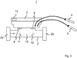
- the heat meter 1 comprises a connection housing 2, by means of which it can be installed in the fluid line system.
- the connection housing 2 comprises an inlet 2a and an outlet 2b, the z. B. as in Fig. 1 shown, each having a flange connection to be connected to corresponding flange ports 22, 23 of the fluid conduit system.
- the heat meter 1 can here either in the flow 20 or, as in Fig. 1 shown installed in the return line 21 of the fluid line system.
- the heat meter 1 also has two temperature sensors 4, 5, which are each arranged in the flow 20 or return 21 of the fluid line system.
- the temperature sensor 4 is arranged via a connection device 6 in the flow 20 and the temperature sensor 5 via a connection device 7 in the return line 21.
- the immersion sleeves are preferably oriented counter to the direction of flow of the fluid.
- temperature sensor 4, 5 can all Types of known from the prior art temperature sensors may be provided, such. As a PT-100, thermocouple or the like.
- the heat quantity meter 1 comprises a control and evaluation unit 3 and, as a measuring arrangement for flow rate determination, an ultrasonic measuring arrangement comprising two ultrasonic transducers 8, 9 and two deflection devices 11, 12.
- the deflecting devices 11, 12 are intended to deflect the ultrasonic waves in such a way that the ultrasonic measuring section 10 is U-shaped passes through the connection housing 2.
- embodiment variants of the fluid meter according to the invention in which the ultrasonic measuring path 10 z. B. straight or multiply deflected by the terminal housing 2 extends.
- the temperature of the heat quantity meter 1 is determined. This temperature corresponds essentially to the fluid temperature at the installation site (flow or return) of the heat quantity meter 1.
- the ultrasonic measuring arrangement is provided for flow rate determination. For this purpose, a temperature difference between the temperature of the heat quantity meter 1 and at least one of the temperatures of the first and second temperature sensor 4, 5 is determined. Based on the determined temperature difference (s) is then determined which of the temperature sensor 4, 5 in the flow 20 and which is installed in the return 21 by the temperature sensor 4, 5 whose temperature has a lower temperature difference to the temperature of the heat quantity meter 1, the installation location heat meter , that is assigned according to the flow 20 or return 21.
- the heat quantity meter 1 comprises a power supply, not shown for the sake of clarity.
- power supply z a battery, in particular a lithium battery (eg an A cell or a D cell with a lifetime of more than 10 years), or a power supply (eg 24 V or 230 V) may be provided .
- an unillustrated communication module may be provided by means of which the heat meter 1 z. B. over radio, L-bus, M-bus, RS-232, RS-458, LAN or the like with a parent unit such.
- B. a data collector can communicate to z. B. operating or consumption data to transfer.
Landscapes
- Physics & Mathematics (AREA)
- General Physics & Mathematics (AREA)
- Fluid Mechanics (AREA)
- Chemical & Material Sciences (AREA)
- Engineering & Computer Science (AREA)
- Combustion & Propulsion (AREA)
- Electromagnetism (AREA)
- Details Of Flowmeters (AREA)
- Measuring Volume Flow (AREA)
Applications Claiming Priority (1)
| Application Number | Priority Date | Filing Date | Title |
|---|---|---|---|
| DE102018003671.6A DE102018003671B4 (de) | 2018-05-05 | 2018-05-05 | Fluidzähler |
Publications (2)
| Publication Number | Publication Date |
|---|---|
| EP3569989A1 true EP3569989A1 (fr) | 2019-11-20 |
| EP3569989B1 EP3569989B1 (fr) | 2023-03-01 |
Family
ID=66286163
Family Applications (1)
| Application Number | Title | Priority Date | Filing Date |
|---|---|---|---|
| EP19170992.2A Active EP3569989B1 (fr) | 2018-05-05 | 2019-04-25 | Compteur de fluide |
Country Status (5)
| Country | Link |
|---|---|
| EP (1) | EP3569989B1 (fr) |
| CN (1) | CN110440862B (fr) |
| DE (1) | DE102018003671B4 (fr) |
| DK (1) | DK3569989T3 (fr) |
| PL (1) | PL3569989T3 (fr) |
Families Citing this family (5)
| Publication number | Priority date | Publication date | Assignee | Title |
|---|---|---|---|---|
| DE102019008243B4 (de) * | 2019-11-27 | 2024-03-14 | Diehl Metering Gmbh | Messeinrichtung |
| DE102020200749A1 (de) | 2020-01-22 | 2021-07-22 | Landis + Gyr Gmbh | Energiezähler und Verfahren zur Erfassung einer Wärme- oder Kältemenge |
| DE202021004042U1 (de) | 2021-06-08 | 2022-06-29 | Landis + Gyr Gmbh | Energiezähler zur Erfassung einer thermischen Energiemenge |
| EP4102198B1 (fr) | 2021-06-08 | 2025-09-03 | Landis+Gyr GmbH | Compteur d'énergie et procédé de détection d'une quantité d'énergie thermique |
| CN118376273B (zh) * | 2024-06-26 | 2024-08-30 | 山东威鸿智能科技有限公司 | 一种热量测量计及其测量方法 |
Citations (5)
| Publication number | Priority date | Publication date | Assignee | Title |
|---|---|---|---|---|
| DE2949346A1 (de) * | 1979-12-07 | 1981-06-11 | Erwin Sick Gmbh Optik-Elektronik, 7808 Waldkirch | Verfahren und schaltungsanordnung zur waermeflussmessung |
| EP2000788A1 (fr) * | 2007-06-06 | 2008-12-10 | Kamstrup A/S | Calculateur d'énergie doté de détection d'erreur d'installation |
| EP2000784A1 (fr) * | 2007-06-06 | 2008-12-10 | Kamstrup A/S | Débitmètre à ultrasons à compensation de température |
| DE102010011272A1 (de) * | 2010-03-13 | 2011-09-15 | Hydrometer Gmbh | Energiezähler |
| DE102015001379A1 (de) * | 2015-02-03 | 2016-08-04 | Diehl Metering Gmbh | Durchflusszähler |
Family Cites Families (7)
| Publication number | Priority date | Publication date | Assignee | Title |
|---|---|---|---|---|
| CN2771840Y (zh) * | 2005-01-06 | 2006-04-12 | 青岛海纳电气自动化系统有限公司 | 串联式热量表 |
| PL2104116T3 (pl) * | 2008-03-12 | 2017-09-29 | Alstom Transport Technologies | Układ chłodzenia olejowego, zwłaszcza transformatorów zasilających trakcyjne silniki elektryczne, transformator ze wspomnianym układem oraz sposób określania przepływu płynu chłodzącego w układzie chłodzenia |
| CN202274952U (zh) * | 2011-10-22 | 2012-06-13 | 威海震宇智能科技有限公司 | 带稳流板的超声波热量表 |
| DE102011087215A1 (de) | 2011-11-28 | 2013-05-29 | Endress + Hauser Flowtec Ag | Verfahren zur Wärmemengenmessung mit einem Ultraschall-Durchflussmessgerät |
| KR101361470B1 (ko) * | 2012-03-02 | 2014-02-11 | (주)씨엠엔텍 | 초음파 유량계 및 열량계 |
| KR20170027856A (ko) * | 2014-07-14 | 2017-03-10 | 마이크로 모우션, 인코포레이티드 | 진동 유량계에서 디퍼렌셜 제로 오프셋을 결정하기 위한 장치 및 관련 방법 |
| JP2016206147A (ja) * | 2015-04-28 | 2016-12-08 | アズビル株式会社 | 超音波式積算熱量計 |
-
2018
- 2018-05-05 DE DE102018003671.6A patent/DE102018003671B4/de active Active
-
2019
- 2019-04-24 CN CN201910331274.1A patent/CN110440862B/zh active Active
- 2019-04-25 PL PL19170992.2T patent/PL3569989T3/pl unknown
- 2019-04-25 EP EP19170992.2A patent/EP3569989B1/fr active Active
- 2019-04-25 DK DK19170992.2T patent/DK3569989T3/da active
Patent Citations (5)
| Publication number | Priority date | Publication date | Assignee | Title |
|---|---|---|---|---|
| DE2949346A1 (de) * | 1979-12-07 | 1981-06-11 | Erwin Sick Gmbh Optik-Elektronik, 7808 Waldkirch | Verfahren und schaltungsanordnung zur waermeflussmessung |
| EP2000788A1 (fr) * | 2007-06-06 | 2008-12-10 | Kamstrup A/S | Calculateur d'énergie doté de détection d'erreur d'installation |
| EP2000784A1 (fr) * | 2007-06-06 | 2008-12-10 | Kamstrup A/S | Débitmètre à ultrasons à compensation de température |
| DE102010011272A1 (de) * | 2010-03-13 | 2011-09-15 | Hydrometer Gmbh | Energiezähler |
| DE102015001379A1 (de) * | 2015-02-03 | 2016-08-04 | Diehl Metering Gmbh | Durchflusszähler |
Also Published As
| Publication number | Publication date |
|---|---|
| DK3569989T3 (da) | 2023-05-30 |
| EP3569989B1 (fr) | 2023-03-01 |
| PL3569989T3 (pl) | 2023-06-05 |
| CN110440862A (zh) | 2019-11-12 |
| CN110440862B (zh) | 2024-07-12 |
| DE102018003671A1 (de) | 2019-11-07 |
| DE102018003671B4 (de) | 2026-03-26 |
Similar Documents
| Publication | Publication Date | Title |
|---|---|---|
| EP3569989B1 (fr) | Compteur de fluide | |
| EP3428583B1 (fr) | Procédé de fonctionnement d'un compteur de fluide et compteur de fluide | |
| EP3234512B1 (fr) | Débitmètre à pression différentielle | |
| EP3084534B1 (fr) | Appareil de terrain pour automatismes de processus | |
| DE102011003438B4 (de) | Einrichtung und Verfahren zur Ermittlung von Messwerten in einem strömenden Medium | |
| DE102007023840A1 (de) | Thermischer Massendurchflussmesser und Verfahren zu dessen Betrieb | |
| WO2014056709A1 (fr) | Système de mesure pour déterminer un débit volumique et/ou un pourcentage de débit volumique d'un fluide s'écoulant dans une tuyauterie | |
| EP3608639B1 (fr) | Procédé de fonctionnement d'un dispositif de mesure | |
| EP3008442A1 (fr) | Système de mesure pourvu d'un appareil sous pression et procédé pour surveiller et/ou contrôler un tel appareil sous pression | |
| EP3008441A1 (fr) | Système de mesure pourvu d'un appareil sous pression et procédé pour surveiller et/ou contrôler un tel appareil sous pression | |
| DE102011087215A1 (de) | Verfahren zur Wärmemengenmessung mit einem Ultraschall-Durchflussmessgerät | |
| EP3056875B1 (fr) | Debitmètre | |
| DE102007011547B4 (de) | Fluidzählanordnung | |
| EP4341651A1 (fr) | Système de mesure vibronique | |
| DE102012109729A1 (de) | Meßsystem zum Ermitteln eines Volumendruchflusses und/oder einer Volumendurchflußrate eines in einer Rohrleitung strömenden Mediums | |
| DE102012022376A1 (de) | Druck- und Durchflussmessung mittels akustischer Wellen | |
| DE102013200685A1 (de) | Feldgerät zur Prozessinstrumentierung | |
| DE102013113365A1 (de) | Verfahren zum Betreiben eines Messvorrichtung | |
| EP4177575B1 (fr) | Détection de pression dans un compteur de fluide à ultrasons au moyen d'un transducteur ultrasonore piézocéramique | |
| DE102017120021A1 (de) | Differenzdruckmessanordnung | |
| EP2366979A1 (fr) | Dispositif et procédé de mesure du débit d'un fluide s'écoulant à travers un tuyau | |
| EP3114439A1 (fr) | Procédé servant à surveiller un appareil de mesure | |
| EP4102198B1 (fr) | Compteur d'énergie et procédé de détection d'une quantité d'énergie thermique | |
| WO2014180564A1 (fr) | Procédé et dispositif de mesure du débit d'un gaz dans une canalisation au moyen d'un compteur de gaz à roue de turbine | |
| DE102010052104A1 (de) | Wärmezähler |
Legal Events
| Date | Code | Title | Description |
|---|---|---|---|
| PUAI | Public reference made under article 153(3) epc to a published international application that has entered the european phase |
Free format text: ORIGINAL CODE: 0009012 |
|
| STAA | Information on the status of an ep patent application or granted ep patent |
Free format text: STATUS: THE APPLICATION HAS BEEN PUBLISHED |
|
| AK | Designated contracting states |
Kind code of ref document: A1 Designated state(s): AL AT BE BG CH CY CZ DE DK EE ES FI FR GB GR HR HU IE IS IT LI LT LU LV MC MK MT NL NO PL PT RO RS SE SI SK SM TR |
|
| AX | Request for extension of the european patent |
Extension state: BA ME |
|
| STAA | Information on the status of an ep patent application or granted ep patent |
Free format text: STATUS: REQUEST FOR EXAMINATION WAS MADE |
|
| 17P | Request for examination filed |
Effective date: 20200319 |
|
| RBV | Designated contracting states (corrected) |
Designated state(s): AL AT BE BG CH CY CZ DE DK EE ES FI FR GB GR HR HU IE IS IT LI LT LU LV MC MK MT NL NO PL PT RO RS SE SI SK SM TR |
|
| STAA | Information on the status of an ep patent application or granted ep patent |
Free format text: STATUS: EXAMINATION IS IN PROGRESS |
|
| 17Q | First examination report despatched |
Effective date: 20211210 |
|
| GRAP | Despatch of communication of intention to grant a patent |
Free format text: ORIGINAL CODE: EPIDOSNIGR1 |
|
| STAA | Information on the status of an ep patent application or granted ep patent |
Free format text: STATUS: GRANT OF PATENT IS INTENDED |
|
| INTG | Intention to grant announced |
Effective date: 20221012 |
|
| GRAS | Grant fee paid |
Free format text: ORIGINAL CODE: EPIDOSNIGR3 |
|
| GRAA | (expected) grant |
Free format text: ORIGINAL CODE: 0009210 |
|
| STAA | Information on the status of an ep patent application or granted ep patent |
Free format text: STATUS: THE PATENT HAS BEEN GRANTED |
|
| AK | Designated contracting states |
Kind code of ref document: B1 Designated state(s): AL AT BE BG CH CY CZ DE DK EE ES FI FR GB GR HR HU IE IS IT LI LT LU LV MC MK MT NL NO PL PT RO RS SE SI SK SM TR |
|
| REG | Reference to a national code |
Ref country code: GB Ref legal event code: FG4D Free format text: NOT ENGLISH |
|
| REG | Reference to a national code |
Ref country code: CH Ref legal event code: EP Ref country code: AT Ref legal event code: REF Ref document number: 1551261 Country of ref document: AT Kind code of ref document: T Effective date: 20230315 |
|
| REG | Reference to a national code |
Ref country code: DE Ref legal event code: R096 Ref document number: 502019007065 Country of ref document: DE |
|
| REG | Reference to a national code |
Ref country code: IE Ref legal event code: FG4D Free format text: LANGUAGE OF EP DOCUMENT: GERMAN |
|
| REG | Reference to a national code |
Ref country code: DK Ref legal event code: T3 Effective date: 20230524 |
|
| REG | Reference to a national code |
Ref country code: SE Ref legal event code: TRGR |
|
| REG | Reference to a national code |
Ref country code: LT Ref legal event code: MG9D |
|
| REG | Reference to a national code |
Ref country code: NL Ref legal event code: MP Effective date: 20230301 |
|
| PG25 | Lapsed in a contracting state [announced via postgrant information from national office to epo] |
Ref country code: RS Free format text: LAPSE BECAUSE OF FAILURE TO SUBMIT A TRANSLATION OF THE DESCRIPTION OR TO PAY THE FEE WITHIN THE PRESCRIBED TIME-LIMIT Effective date: 20230301 Ref country code: NO Free format text: LAPSE BECAUSE OF FAILURE TO SUBMIT A TRANSLATION OF THE DESCRIPTION OR TO PAY THE FEE WITHIN THE PRESCRIBED TIME-LIMIT Effective date: 20230601 Ref country code: LV Free format text: LAPSE BECAUSE OF FAILURE TO SUBMIT A TRANSLATION OF THE DESCRIPTION OR TO PAY THE FEE WITHIN THE PRESCRIBED TIME-LIMIT Effective date: 20230301 Ref country code: LT Free format text: LAPSE BECAUSE OF FAILURE TO SUBMIT A TRANSLATION OF THE DESCRIPTION OR TO PAY THE FEE WITHIN THE PRESCRIBED TIME-LIMIT Effective date: 20230301 Ref country code: HR Free format text: LAPSE BECAUSE OF FAILURE TO SUBMIT A TRANSLATION OF THE DESCRIPTION OR TO PAY THE FEE WITHIN THE PRESCRIBED TIME-LIMIT Effective date: 20230301 Ref country code: ES Free format text: LAPSE BECAUSE OF FAILURE TO SUBMIT A TRANSLATION OF THE DESCRIPTION OR TO PAY THE FEE WITHIN THE PRESCRIBED TIME-LIMIT Effective date: 20230301 |
|
| PG25 | Lapsed in a contracting state [announced via postgrant information from national office to epo] |
Ref country code: NL Free format text: LAPSE BECAUSE OF FAILURE TO SUBMIT A TRANSLATION OF THE DESCRIPTION OR TO PAY THE FEE WITHIN THE PRESCRIBED TIME-LIMIT Effective date: 20230301 Ref country code: GR Free format text: LAPSE BECAUSE OF FAILURE TO SUBMIT A TRANSLATION OF THE DESCRIPTION OR TO PAY THE FEE WITHIN THE PRESCRIBED TIME-LIMIT Effective date: 20230602 Ref country code: FI Free format text: LAPSE BECAUSE OF FAILURE TO SUBMIT A TRANSLATION OF THE DESCRIPTION OR TO PAY THE FEE WITHIN THE PRESCRIBED TIME-LIMIT Effective date: 20230301 |
|
| PG25 | Lapsed in a contracting state [announced via postgrant information from national office to epo] |
Ref country code: SM Free format text: LAPSE BECAUSE OF FAILURE TO SUBMIT A TRANSLATION OF THE DESCRIPTION OR TO PAY THE FEE WITHIN THE PRESCRIBED TIME-LIMIT Effective date: 20230301 Ref country code: RO Free format text: LAPSE BECAUSE OF FAILURE TO SUBMIT A TRANSLATION OF THE DESCRIPTION OR TO PAY THE FEE WITHIN THE PRESCRIBED TIME-LIMIT Effective date: 20230301 Ref country code: PT Free format text: LAPSE BECAUSE OF FAILURE TO SUBMIT A TRANSLATION OF THE DESCRIPTION OR TO PAY THE FEE WITHIN THE PRESCRIBED TIME-LIMIT Effective date: 20230703 Ref country code: EE Free format text: LAPSE BECAUSE OF FAILURE TO SUBMIT A TRANSLATION OF THE DESCRIPTION OR TO PAY THE FEE WITHIN THE PRESCRIBED TIME-LIMIT Effective date: 20230301 Ref country code: CZ Free format text: LAPSE BECAUSE OF FAILURE TO SUBMIT A TRANSLATION OF THE DESCRIPTION OR TO PAY THE FEE WITHIN THE PRESCRIBED TIME-LIMIT Effective date: 20230301 |
|
| PG25 | Lapsed in a contracting state [announced via postgrant information from national office to epo] |
Ref country code: SK Free format text: LAPSE BECAUSE OF FAILURE TO SUBMIT A TRANSLATION OF THE DESCRIPTION OR TO PAY THE FEE WITHIN THE PRESCRIBED TIME-LIMIT Effective date: 20230301 Ref country code: IS Free format text: LAPSE BECAUSE OF FAILURE TO SUBMIT A TRANSLATION OF THE DESCRIPTION OR TO PAY THE FEE WITHIN THE PRESCRIBED TIME-LIMIT Effective date: 20230701 |
|
| REG | Reference to a national code |
Ref country code: CH Ref legal event code: PL |
|
| REG | Reference to a national code |
Ref country code: DE Ref legal event code: R097 Ref document number: 502019007065 Country of ref document: DE |
|
| PG25 | Lapsed in a contracting state [announced via postgrant information from national office to epo] |
Ref country code: LU Free format text: LAPSE BECAUSE OF NON-PAYMENT OF DUE FEES Effective date: 20230425 |
|
| PLBE | No opposition filed within time limit |
Free format text: ORIGINAL CODE: 0009261 |
|
| STAA | Information on the status of an ep patent application or granted ep patent |
Free format text: STATUS: NO OPPOSITION FILED WITHIN TIME LIMIT |
|
| REG | Reference to a national code |
Ref country code: BE Ref legal event code: MM Effective date: 20230430 |
|
| PG25 | Lapsed in a contracting state [announced via postgrant information from national office to epo] |
Ref country code: MC Free format text: LAPSE BECAUSE OF FAILURE TO SUBMIT A TRANSLATION OF THE DESCRIPTION OR TO PAY THE FEE WITHIN THE PRESCRIBED TIME-LIMIT Effective date: 20230301 |
|
| PG25 | Lapsed in a contracting state [announced via postgrant information from national office to epo] |
Ref country code: SI Free format text: LAPSE BECAUSE OF FAILURE TO SUBMIT A TRANSLATION OF THE DESCRIPTION OR TO PAY THE FEE WITHIN THE PRESCRIBED TIME-LIMIT Effective date: 20230301 Ref country code: MC Free format text: LAPSE BECAUSE OF FAILURE TO SUBMIT A TRANSLATION OF THE DESCRIPTION OR TO PAY THE FEE WITHIN THE PRESCRIBED TIME-LIMIT Effective date: 20230301 Ref country code: LI Free format text: LAPSE BECAUSE OF NON-PAYMENT OF DUE FEES Effective date: 20230430 Ref country code: CH Free format text: LAPSE BECAUSE OF NON-PAYMENT OF DUE FEES Effective date: 20230430 |
|
| 26N | No opposition filed |
Effective date: 20231204 |
|
| REG | Reference to a national code |
Ref country code: IE Ref legal event code: MM4A |
|
| PG25 | Lapsed in a contracting state [announced via postgrant information from national office to epo] |
Ref country code: BE Free format text: LAPSE BECAUSE OF NON-PAYMENT OF DUE FEES Effective date: 20230430 |
|
| PG25 | Lapsed in a contracting state [announced via postgrant information from national office to epo] |
Ref country code: IE Free format text: LAPSE BECAUSE OF NON-PAYMENT OF DUE FEES Effective date: 20230425 |
|
| PG25 | Lapsed in a contracting state [announced via postgrant information from national office to epo] |
Ref country code: IE Free format text: LAPSE BECAUSE OF NON-PAYMENT OF DUE FEES Effective date: 20230425 |
|
| PG25 | Lapsed in a contracting state [announced via postgrant information from national office to epo] |
Ref country code: IT Free format text: LAPSE BECAUSE OF FAILURE TO SUBMIT A TRANSLATION OF THE DESCRIPTION OR TO PAY THE FEE WITHIN THE PRESCRIBED TIME-LIMIT Effective date: 20230301 |
|
| PG25 | Lapsed in a contracting state [announced via postgrant information from national office to epo] |
Ref country code: BG Free format text: LAPSE BECAUSE OF FAILURE TO SUBMIT A TRANSLATION OF THE DESCRIPTION OR TO PAY THE FEE WITHIN THE PRESCRIBED TIME-LIMIT Effective date: 20230301 |
|
| PG25 | Lapsed in a contracting state [announced via postgrant information from national office to epo] |
Ref country code: BG Free format text: LAPSE BECAUSE OF FAILURE TO SUBMIT A TRANSLATION OF THE DESCRIPTION OR TO PAY THE FEE WITHIN THE PRESCRIBED TIME-LIMIT Effective date: 20230301 |
|
| REG | Reference to a national code |
Ref country code: AT Ref legal event code: MM01 Ref document number: 1551261 Country of ref document: AT Kind code of ref document: T Effective date: 20240425 |
|
| PGFP | Annual fee paid to national office [announced via postgrant information from national office to epo] |
Ref country code: PL Payment date: 20250418 Year of fee payment: 7 Ref country code: DE Payment date: 20250612 Year of fee payment: 7 |
|
| PGFP | Annual fee paid to national office [announced via postgrant information from national office to epo] |
Ref country code: GB Payment date: 20250423 Year of fee payment: 7 Ref country code: DK Payment date: 20250429 Year of fee payment: 7 |
|
| PGFP | Annual fee paid to national office [announced via postgrant information from national office to epo] |
Ref country code: FR Payment date: 20250425 Year of fee payment: 7 |
|
| PG25 | Lapsed in a contracting state [announced via postgrant information from national office to epo] |
Ref country code: AT Free format text: LAPSE BECAUSE OF NON-PAYMENT OF DUE FEES Effective date: 20240425 |
|
| PG25 | Lapsed in a contracting state [announced via postgrant information from national office to epo] |
Ref country code: CY Free format text: LAPSE BECAUSE OF FAILURE TO SUBMIT A TRANSLATION OF THE DESCRIPTION OR TO PAY THE FEE WITHIN THE PRESCRIBED TIME-LIMIT; INVALID AB INITIO Effective date: 20190425 |
|
| PGFP | Annual fee paid to national office [announced via postgrant information from national office to epo] |
Ref country code: SE Payment date: 20250429 Year of fee payment: 7 |
|
| PG25 | Lapsed in a contracting state [announced via postgrant information from national office to epo] |
Ref country code: HU Free format text: LAPSE BECAUSE OF FAILURE TO SUBMIT A TRANSLATION OF THE DESCRIPTION OR TO PAY THE FEE WITHIN THE PRESCRIBED TIME-LIMIT; INVALID AB INITIO Effective date: 20190425 |
|
| PG25 | Lapsed in a contracting state [announced via postgrant information from national office to epo] |
Ref country code: TR Free format text: LAPSE BECAUSE OF FAILURE TO SUBMIT A TRANSLATION OF THE DESCRIPTION OR TO PAY THE FEE WITHIN THE PRESCRIBED TIME-LIMIT Effective date: 20230301 |
|
| PGFP | Annual fee paid to national office [announced via postgrant information from national office to epo] |
Ref country code: AT Payment date: 20260410 Year of fee payment: 5 |