EP4177575B1 - Détection de pression dans un compteur de fluide à ultrasons au moyen d'un transducteur ultrasonore piézocéramique - Google Patents
Détection de pression dans un compteur de fluide à ultrasons au moyen d'un transducteur ultrasonore piézocéramique Download PDFInfo
- Publication number
- EP4177575B1 EP4177575B1 EP22205170.8A EP22205170A EP4177575B1 EP 4177575 B1 EP4177575 B1 EP 4177575B1 EP 22205170 A EP22205170 A EP 22205170A EP 4177575 B1 EP4177575 B1 EP 4177575B1
- Authority
- EP
- European Patent Office
- Prior art keywords
- fluid
- ultrasonic
- voltage
- voltage signal
- fluid pressure
- Prior art date
- Legal status (The legal status is an assumption and is not a legal conclusion. Google has not performed a legal analysis and makes no representation as to the accuracy of the status listed.)
- Active
Links
Images

Classifications
-
- G—PHYSICS
- G01—MEASURING; TESTING
- G01F—MEASURING VOLUME, VOLUME FLOW, MASS FLOW OR LIQUID LEVEL; METERING BY VOLUME
- G01F1/00—Measuring the volume flow or mass flow of fluid or fluent solid material wherein the fluid passes through a meter in a continuous flow
- G01F1/66—Measuring the volume flow or mass flow of fluid or fluent solid material wherein the fluid passes through a meter in a continuous flow by measuring frequency, phase shift or propagation time of electromagnetic or other waves, e.g. using ultrasonic flowmeters
- G01F1/662—Constructional details
-
- G—PHYSICS
- G01—MEASURING; TESTING
- G01F—MEASURING VOLUME, VOLUME FLOW, MASS FLOW OR LIQUID LEVEL; METERING BY VOLUME
- G01F1/00—Measuring the volume flow or mass flow of fluid or fluent solid material wherein the fluid passes through a meter in a continuous flow
- G01F1/66—Measuring the volume flow or mass flow of fluid or fluent solid material wherein the fluid passes through a meter in a continuous flow by measuring frequency, phase shift or propagation time of electromagnetic or other waves, e.g. using ultrasonic flowmeters
- G01F1/667—Arrangements of transducers for ultrasonic flowmeters; Circuits for operating ultrasonic flowmeters
-
- G—PHYSICS
- G01—MEASURING; TESTING
- G01F—MEASURING VOLUME, VOLUME FLOW, MASS FLOW OR LIQUID LEVEL; METERING BY VOLUME
- G01F15/00—Details of, or accessories for, apparatus of groups G01F1/00 - G01F13/00 insofar as such details or appliances are not adapted to particular types of such apparatus
- G01F15/02—Compensating or correcting for variations in pressure, density or temperature
- G01F15/022—Compensating or correcting for variations in pressure, density or temperature using electrical means
- G01F15/024—Compensating or correcting for variations in pressure, density or temperature using electrical means involving digital counting
-
- G—PHYSICS
- G01—MEASURING; TESTING
- G01L—MEASURING FORCE, STRESS, TORQUE, WORK, MECHANICAL POWER, MECHANICAL EFFICIENCY, OR FLUID PRESSURE
- G01L9/00—Measuring steady of quasi-steady pressure of fluid or fluent solid material by electric or magnetic pressure-sensitive elements; Transmitting or indicating the displacement of mechanical pressure-sensitive elements, used to measure the steady or quasi-steady pressure of a fluid or fluent solid material, by electric or magnetic means
- G01L9/0001—Transmitting or indicating the displacement of elastically deformable gauges by electric, electro-mechanical, magnetic or electro-magnetic means
- G01L9/0008—Transmitting or indicating the displacement of elastically deformable gauges by electric, electro-mechanical, magnetic or electro-magnetic means using vibrations
- G01L9/0022—Transmitting or indicating the displacement of elastically deformable gauges by electric, electro-mechanical, magnetic or electro-magnetic means using vibrations of a piezoelectric element
-
- G—PHYSICS
- G01—MEASURING; TESTING
- G01L—MEASURING FORCE, STRESS, TORQUE, WORK, MECHANICAL POWER, MECHANICAL EFFICIENCY, OR FLUID PRESSURE
- G01L9/00—Measuring steady of quasi-steady pressure of fluid or fluent solid material by electric or magnetic pressure-sensitive elements; Transmitting or indicating the displacement of mechanical pressure-sensitive elements, used to measure the steady or quasi-steady pressure of a fluid or fluent solid material, by electric or magnetic means
- G01L9/08—Measuring steady of quasi-steady pressure of fluid or fluent solid material by electric or magnetic pressure-sensitive elements; Transmitting or indicating the displacement of mechanical pressure-sensitive elements, used to measure the steady or quasi-steady pressure of a fluid or fluent solid material, by electric or magnetic means by making use of piezoelectric devices, i.e. electric circuits therefor
-
- G—PHYSICS
- G01—MEASURING; TESTING
- G01L—MEASURING FORCE, STRESS, TORQUE, WORK, MECHANICAL POWER, MECHANICAL EFFICIENCY, OR FLUID PRESSURE
- G01L9/00—Measuring steady of quasi-steady pressure of fluid or fluent solid material by electric or magnetic pressure-sensitive elements; Transmitting or indicating the displacement of mechanical pressure-sensitive elements, used to measure the steady or quasi-steady pressure of a fluid or fluent solid material, by electric or magnetic means
- G01L9/12—Measuring steady of quasi-steady pressure of fluid or fluent solid material by electric or magnetic pressure-sensitive elements; Transmitting or indicating the displacement of mechanical pressure-sensitive elements, used to measure the steady or quasi-steady pressure of a fluid or fluent solid material, by electric or magnetic means by making use of variations in capacitance, i.e. electric circuits therefor
-
- G—PHYSICS
- G01—MEASURING; TESTING
- G01M—TESTING STATIC OR DYNAMIC BALANCE OF MACHINES OR STRUCTURES; TESTING OF STRUCTURES OR APPARATUS, NOT OTHERWISE PROVIDED FOR
- G01M3/00—Investigating fluid-tightness of structures
- G01M3/02—Investigating fluid-tightness of structures by using fluid or vacuum
- G01M3/26—Investigating fluid-tightness of structures by using fluid or vacuum by measuring rate of loss or gain of fluid, e.g. by pressure-responsive devices, by flow detectors
- G01M3/28—Investigating fluid-tightness of structures by using fluid or vacuum by measuring rate of loss or gain of fluid, e.g. by pressure-responsive devices, by flow detectors for pipes, cables or tubes; for pipe joints or seals; for valves ; for welds
- G01M3/2807—Investigating fluid-tightness of structures by using fluid or vacuum by measuring rate of loss or gain of fluid, e.g. by pressure-responsive devices, by flow detectors for pipes, cables or tubes; for pipe joints or seals; for valves ; for welds for pipes
Definitions
- the present invention relates, on the one hand, to a method for operating an ultrasonic fluid meter according to the preamble of claim 1 and, on the other hand, to an ultrasonic fluid meter according to the preamble of claim 16.
- Ultrasonic fluid meters are used to determine the flow of fluid in a fluid line network, for example a water line network.
- a fluid line network the fluid is under pressure.
- a flow measurement or fluid volume flow measurement is carried out based on a measurement of the transit time of an ultrasonic signal passing through the fluid. The transit time is measured once with and once against the direction of flow. The fluid flow or fluid volume flow can be determined from the transit time difference.
- Ultrasonic fluid meters are usually supplied with electrical energy from a battery. The battery capacity of such a battery covers the entire service life of the ultrasonic fluid meter in the field. The service life of an ultrasonic fluid meter is usually in the range of 12 to 16 years.
- measuring the pressure or pressure changes in the fluid line network is also of particular interest.
- independent pressure measuring devices are usually installed in the fluid line network.
- fluid meters can be equipped with an additional, independent pressure measuring device or pressure sensor. Accordingly, independent sensors are required for both pressure measurement and flow measurement. This significantly increases the production costs of the ultrasonic fluid meter.
- the EP 3 367 074 A1 describes an electronic fluid flow meter which comprises two ultrasonic transducers.
- the ultrasonic transducers are positioned to transmit ultrasonic signals through a first wall.
- the flow meter also includes an independent built-in pressure sensor, which is arranged in a sensor bore.
- the pressure sensor includes a sensor housing in the form of a flexible membrane, which seals the sensor bore against the fluid.
- a sensor element detects membrane changes based on the fluid pressure and uses this to determine a pressure or a pressure change in the fluid.
- the sensor element can be based on inductive, capacitive, piezoelectric or strain gauge-based technologies.
- the EP 3 158 297 B1 describes an ultrasonic flow meter for measuring the flow rate of a fluid, which comprises two ultrasonic transducers on the outer surface of a flow tube.
- the ultrasonic transducers are arranged to transmit ultrasonic signals through a wall of the flow tube.
- the ultrasonic flow meter comprises two strain gauges on the outer surface of the flow tube which produce a signal indicative of the pressure of the fluid.
- the strain gauges are also arranged on the outer surface of the flow tube and measure the strain of the flow tube in response to the pressure of the fluid.
- the EN 10 2012 022376 A1 describes a method for measuring the pressure and flow rate of a fluid in a container.
- at least one ultrasonic transmitting/receiving unit comprises an elastic membrane that delimits a lumen from the fluid.
- the fluid pressure can be determined by determining the resonance frequency of an ultrasonic signal along an ultrasonic path.
- the WO 2018/219492 A1 discloses an ultrasonic flow meter that emits two ultrasonic signals in the direction of flow and two against the direction of flow at different frequencies to determine the pressure along a measuring section. Based on the ultrasonic signals, a phase-frequency offset between the two frequencies in the direction of flow and against the direction of flow is determined. From this, an average value of the phase-frequency offset is determined and the pressure is determined from this.
- the EP 3 798 600 A1 describes a measuring device for determining a fluid pressure in a flow-through measuring volume. An offset is determined between an excitation pattern and an output signal, which can be used to determine the fluid pressure in the measuring volume.
- the EN 10 2020 122128 B3 describes a pressure measurement in a pressure measuring cell based on a capacitive pressure measuring device.
- the object of the present invention is to provide a method for operating an ultrasonic fluid meter or an ultrasonic fluid meter which enables a cost-effective and easy-to-integrate measurement of the fluid pressure.
- the voltage signal curve is tapped by the evaluation electronics and a fluid pressure change is derived based on the voltage of the voltage signal curve.
- the level curve or the voltage of the voltage signal curve depends on the strength and duration of the hydraulic force change acting on the ultrasonic transducer, i.e. on the pulse acting on the ultrasonic transducer. The greater the hydraulic force change, the greater the level curve or the voltage and vice versa.
- the level curve or the voltage, ie the amplitude of the voltage signal curve and the hydraulic force change are proportional to each other.
- a pressure and/or a pressure change in the fluid line network can be determined by means of the tapped voltage signals and/or by means of the derived pressure values or pressure change values.
- the voltage signal curve or the voltage signals can be tapped by the evaluation electronics with high impedance.
- the resistance applied by the tap e.g. the input resistance of an operational amplifier, is preferably at least 1,000 times greater than the ohmic equivalent resistance of the ultrasonic transducer.
- the resistance applied is expediently greater than 750 M ⁇ , preferably greater than 900 M ⁇ , particularly preferably greater than 1 G ⁇ .
- the voltage signal or voltage signal curve picked up by the evaluation electronics can be amplified or attenuated.
- a measuring capacitor that has been charged beforehand, preferably to a predetermined voltage level, can be expediently discharged.
- the tapped voltage signals or the tapped voltage signal curve are fed to the measuring capacitor and this is discharged depending on the voltage signals or the voltage signal curve.
- the measuring capacitor is discharged to different degrees.
- the measuring capacitor is preferably arranged in an evaluation circuit which comprises a semiconductor component, e.g. an n-channel MOSFET, which discharges the measuring capacitor depending on the level of the voltage signals present at its control connection or gate connection or the level curve of the voltage signal curve.
- the discharge behavior of the measuring capacitor can thus be used to determine the hydraulic force change exerted by the fluid on the ultrasonic transducer.
- the charge levels of the measuring capacitor determined after a specified discharge time or time interval are comparable with each other.
- the measuring capacitor is recharged to the previously defined voltage level and discharged again, e.g. with the voltage signals or the voltage signal curve.
- the defined discharge time or the defined time interval is preferably 20 to 40 s, preferably 25 to 35 s, particularly preferably 28 to 32 s.
- the long discharge times and the interval or frequency for determining the charge level determined by the discharge times ensure particularly energy-saving operation.
- the charge level of the measuring capacitor digitally, for example by measuring or reading the charging voltage of the measuring capacitor using an analog-digital converter. This means that a component that is already present in the ultrasonic fluid meter can be used.
- the charge level of the measuring capacitor can be evaluated analogously, e.g. using an analog circuit.
- the charging voltage of the measuring capacitor is reduced via a known resistor after the discharge time has elapsed and the time period until the charging voltage has reduced to a defined reference value is measured. Since the time period corresponds to the charge level of the measuring capacitor, this can be converted into the charge level of the measuring capacitor.
- a corresponding, e.g. relative, fluid pressure change can be determined from the determined charge state of the measuring capacitor or the determined time period until the charging voltage of the measuring capacitor is reduced to a defined reference value using a characteristic map.
- the determined charge state of the measuring capacitor can also be compared with a reference charge state in order to determine a fluid pressure change.
- the map can be a lookup table or a polynomial.
- the existing fluid pressure can be determined, for example, by integrating or accumulating the measured fluid pressure change in conjunction with an initial value representing the pressure in the fluid line network, e.g. when installing the fluid meter.
- pressure surges within it in particular can be detected. These cause, for example, a higher mechanical load on the fluid line network, which can cause the components installed in the fluid line network to wear out more quickly.
- the fluid line network monitoring can therefore preventively alert the user that individual components of the fluid line network need to be replaced.
- energy-efficient pump operation can be made possible in particular.
- a head end is in particular a logic node or a central data management system.
- the head end can preferably be attached to the ultrasonic fluid meter or to an external concentrator.
- the functions or characteristic values can advantageously be output by means of a display and/or a data interface on the ultrasonic fluid meter and/or on the head end so that the user and/or end customer is informed about them.
- the present invention further relates to an ultrasonic fluid meter, preferably an ultrasonic water meter, according to the preamble of claim 16.
- the ultrasonic fluid meter is operated according to a method according to one of claims 1 to 15.
- the ultrasonic fluid meter is provided with a data interface for data export.
- the ultrasonic transducer can be exposed directly to the fluid.
- a metal plate or a metal membrane or a plastic plate or a plastic membrane can be provided between the ultrasonic transducer and the fluid, which transmits the hydraulic force or force change to the ultrasonic transducer.
- the metal membrane or the plastic membrane preferably has a thickness of 0.1 to 0.3 mm.
- An ultrasonic fluid meter 1 e.g. a water meter, has a housing, e.g. a measuring tube housing 2, which is installed in a fluid line network 3, e.g. a supply line for cold or hot water.
- the ultrasonic fluid meter 1 has, for example, two ultrasonic transducers 4, of which one ultrasonic transducer is closer to the inlet (see arrow in Fig.1 ) than the other ultrasonic transducer.
- the ultrasonic transducers 4 are located, for example, in a bore the wall of the measuring tube housing 2 and are oriented with their respective surface normal N perpendicular to the flow direction of the fluid within the measuring tube housing 2.
- Each ultrasonic transducer 4 comprises a piezoelectric element in the form of a piezoceramic plate, which is coated on both sides along its main surfaces with (in Fig.1 not shown) electrodes that are wired in an electronic module 7 that is located on the top of the measuring tube housing 2.
- the electronic module 7 contains control and evaluation electronics 14 for controlling the operation and for evaluating the received ultrasonic signal.
- the piezoceramic plate can be directly exposed to the fluid.
- a metal plate or a metal membrane or a plastic plate or a plastic membrane can be provided between the piezoceramic plate and the fluid, which transmits the hydraulic force or force change to the piezoceramic plate.
- the measuring section 6 of the Fig.1 The shape of the example of the ultrasonic fluid meter 1 shown is U-shaped. However, it can also have other shapes such as W-shape or double W-shape, in which more than two deflections take place or more deflection mirrors are provided.
- Fig. 2 shows in a highly simplified schematic representation the essential functional elements of the electronic module 7 of an ultrasonic fluid meter 1.
- the electronic module 7 comprises a circuit board 13 with a microprocessor 8 with a memory 9.
- a battery 10 is provided, which ensures the service life of the ultrasonic fluid meter in the field.
- Such ultrasonic fluid meters are designed for a service life of at least 12 years, so that the battery 10 must ensure the function of the ultrasonic fluid meter 1 over this long period of time.
- a display 12 can be located on the ultrasonic fluid meter 1.
- the data generated by the ultrasonic fluid meter 1 is output via a data interface 11.
- the data collector can either be fixed or mobile.
- the data from the ultrasonic fluid meter 1 is usually transmitted from the data collector to a head end (also not shown). The data is evaluated in the head end.
- a hydraulic force change acting on the ultrasonic transducer 4 via the fluid generates a voltage signal U at the ultrasonic transducer, which is tapped according to the invention by means of the evaluation electronics 14.
- the hydraulic force change is caused by a fluid pressure change.
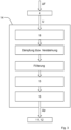
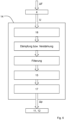
- Fig.3 shows an example process sequence for the digital evaluation of the determined voltage signal curve U. If a force or force change ⁇ F acts on the ultrasonic transducer 4, this generates a voltage signal curve U due to the piezoelectric effect.
- the piezoelectric effect describes the occurrence of an electrical voltage on solid bodies when they are elastically deformed.
- a hydraulic force change ⁇ F 3 acts on the piezoceramic ultrasonic transducer 4 with a piezoelectric voltage constant gas, an electrode distance t and the surface of the piezoceramic A PZT , the voltage signal U i is generated.
- the present invention uses these properties, which every piezoceramic ultrasonic transducer 4 and, accordingly, every ultrasonic fluid meter 1 already has. Additional sensors are therefore not required, which is why the method is particularly easy to implement and cost-effective.
- the voltage signal curve U generated by the hydraulic force change on the ultrasonic transducer 4 is tapped, for example, by means of an operational amplifier 18 of the evaluation electronics 14, preferably with high impedance.
- the voltage signals U i can be tapped continuously.
- the voltage signals U i or the voltage signal curve U are dampened or amplified.
- the voltage signals U i or the voltage signal curve U are then filtered to remove interference signals.
- the preprocessing of the voltage signal curve U is hereby completed.
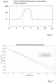
- Fig.4 shows an example of a voltage signal curve U in mV generated at the ultrasonic transducer 4 as a function of time t in s after preprocessing. Due to an increase in fluid pressure, a hydraulic force change is exerted on the ultrasonic transducer 4, whereby the voltage of the voltage signal curve U increases significantly. As soon as there is a constant or static fluid pressure in the fluid line network, the voltage generated at the ultrasonic transducer 4 is automatically reduced by its internal resistance. The voltage signal curve U thus drops and reaches the voltage value 0 V. A deflection of the voltage signal curve U therefore only represents a relative change in fluid pressure. If the voltage of the voltage signal curve is 0 V, there is a static fluid pressure. Due to a reduction in fluid pressure, the voltage signal can also drop and assume negative values.
- the voltage signal U is then evaluated and fed to an evaluation circuit 15, see Fig.3
- the evaluation circuit 15 comprises a semiconductor component, e.g. an n-channel MOSFET, which, depending on of the level curve or voltage of the voltage signal curve U present at its control connection or gate connection discharges a measuring capacitor, preferably charged to a known voltage level.
- the measuring capacitor is discharged to different degrees over a measuring time in s, e.g. 30 s, as shown in Fig.5 represents.
- the Fig.5 shows, on the one hand, the course of the charge state U C,mess in mV of the measuring capacitor over the measuring time, which is discharged with a voltage signal curve based on no change in fluid pressure.
- the charge state of the measuring capacitor is digitally evaluated and read out using an analog-digital converter 16.
- the measured charge state is converted into a corresponding fluid pressure change ⁇ p using a characteristic map, preferably a lookup table or a polynomial.
- the measuring capacitor is recharged to the known voltage level and discharged again.
- the charge state of the measuring capacitor can also be evaluated analogously via an analog circuit 17, see Fig.6 .
- a voltage signal curve U is tapped as in the digital evaluation and a measuring capacitor is discharged with it.
- the charging voltage of the measuring capacitor is reduced via a known resistance and the time required for the discharge process is measured.
- the measured time period is therefore related to the charging voltage of the measuring capacitor.
- the measured time period can be converted into a corresponding fluid pressure change ⁇ p using a characteristic map.
- the charging voltage of the measuring capacitor can first be calculated using the time period and the latter can then be converted into a corresponding fluid pressure change ⁇ p using a characteristic map.
- the characteristic map can, as with the analog evaluation, be a lookup table or a polynomial.
- the static fluid pressure present in the fluid line network can be determined based on the voltage signal curve U.
- the existing static fluid pressure can be determined by integrating or accumulating the voltage signal curve U or integrating or accumulating the tapped voltage signals or integrating or accumulating fluid pressure values or fluid pressure change values derived from the voltage signal curve in conjunction with a known initial value representing the pressure in the fluid line network 3, which was determined, for example, when the ultrasonic fluid meter 1 was installed.
- leak detection and/or monitoring of the fluid line network 3 and/or control of the pump output of the supplier for the fluid line network 3 can be implemented.
- various characteristic values can be determined or various functions can be implemented. The determination of the characteristic values or the implementation of the functions is expediently carried out in a head end. These characteristics or functions can be made available to the user via the display 12 or exported via the data interface 11.
- the method according to the invention makes it possible to detect a change in fluid pressure using the sensors already present in the ultrasonic fluid meter 1. Since no additional sensors need to be used, this method is particularly easy to implement. In addition, the method can be implemented in a simple and cost-effective manner, since only the evaluation electronics 14 or the associated operating software need to be adapted accordingly.
Landscapes
- Physics & Mathematics (AREA)
- General Physics & Mathematics (AREA)
- Fluid Mechanics (AREA)
- Electromagnetism (AREA)
- Measuring Fluid Pressure (AREA)
- Measuring Volume Flow (AREA)
Claims (17)
- Procédé de fonctionnement d'un compteur de fluide à ultrasons (1), de préférence un compteur d'eau à ultrasons, dans un réseau de conduites de fluide (3), procédé dans lequel un transducteur à ultrasons (4) génère un signal ultrasonore qui se propage à travers une section de mesure (6) et une électronique d'évaluation (14) détermine le volume d'écoulement sur la base du temps de propagation et/ou d'une différence de temps de propagation du signal ultrasonore, caractérisé en ce queune variation de force hydraulique, agissant par le biais du fluide sur le transducteur à ultrasons (4) et provoquée par une variation de pression de fluide, génère une courbe de signal de tension au niveau du transducteur à ultrasons (4), la tension de la courbe de signal de tension dépendant de l'intensité et de la durée d'action de la variation de force hydraulique,la courbe de signal de tension est captée par l'électronique d'évaluation (14) etune variation de pression de fluide est dérivée sur la base de la tension de la courbe de signal de tension.
- Procédé selon la revendication 1, caractérisé en ce que les signaux de tension sont captés de manière continue ou discontinue afin de capter la courbe de signal de tension.
- Procédé selon la revendication 1 ou 2, caractérisé en ce qu'une intégration ou accumulation des signaux de tension captés ou une intégration ou accumulation de valeurs de pression de fluide ou de valeurs de variation de pression de fluide dérivées des valeurs de tension captées ou une intégration ou accumulation de valeurs de pression de fluide ou de valeurs de variation de pression de fluide dérivées de la courbe de signal de tension est effectuée.
- Procédé selon les revendications précédentes, caractérisé en ce qu'une valeur initiale est spécifiée qui est représentative de la pression dans le réseau de conduites fluidiques (3).
- Procédé selon les revendications précédentes, caractérisé en ce que la courbe de signal de tension est captée avec une résistance élevée par l'électronique d'évaluation (14).
- Procédé selon l'une des revendications précédentes, caractérisé en ce que les signaux de tension ou la courbe de signal de tension sont amplifiés ou atténués.
- Procédé selon l'une des revendications précédentes, caractérisé en ce que les signaux de tension ou la courbe de signal de tension sont filtrés.
- Procédé selon l'une des revendications précédentes, caractérisé en ce qu'un condensateur de mesure préalablement chargé, de préférence jusqu'à un niveau de tension fixé à l'avance, est déchargé.
- Procédé selon la revendication 8, caractérisé en ce que l'état de charge du condensateur de mesure est déterminé à chaque fois après un temps de décharge fixé.
- Procédé selon la revendication 9, caractérisé en ce que l'état de charge du condensateur de mesure est évalué numériquement.
- Procédé selon la revendication 9, caractérisé en ce que l'état de charge du condensateur de mesure est évalué analogiquement.
- Procédé selon l'une des revendications 9 à 11, caractérisé en ce qu'une variation de pression de fluide correspondante est déterminée à partir de l'état de charge déterminé du condensateur de mesure à l'aide d'un diagramme caractéristique.
- Procédé selon la revendication 12, caractérisé en ce que le diagramme caractéristique est une table de consultation ou un polynôme.
- Procédé selon l'une des revendications précédentes, caractérisé en ce que les étapes suivantes sont réalisées à partir de la courbe de signal de tension :déterminer une pression de fluide et/oudétecter une fuite et/ousurveiller le réseau de conduites de fluide (3) et/ouréguler la commande des performances de la pompe du fournisseur du réseau de conduites de fluide (3).
- Procédé selon la revendication 14, caractérisé en ce que la définition d'une variation de pression de fluide et/ou la détermination d'une pression de fluide et/ou la détection d'une fuite et/ou la surveillance du réseau de conduites de fluide (3) et/ou la régulation de la commande de la puissance de la pompe du fournisseur du réseau de conduites de fluide (3) sont réalisées par une tête de réseau.
- Compteur de fluide à ultrasons (1), de préférence compteur d'eau à ultrasons, destiné à l'installation dans un réseau de conduites de fluide, ledit compteur de fluide à ultrasons comprenantun boîtier de tube de mesure (2),au moins un transducteur à ultrasons (4) destiné à émettre et/ou recevoir un signal ultrasonore qui se propage le long d'une section de mesure (6),un module électronique (7) qui contient une électronique de commande et d'évaluation (14) destinée à commander le fonctionnement et à évaluer le signal ultrasonore reçu, etune batterie (10), caractérisé en ce quele compteur de fluide à ultrasons (1) fonctionne selon un procédé selon l'une des revendications précédentes.
- Compteur de fluide à ultrasons (1) selon la revendication 16, caractérisé en ce qu'une interface de données (11) est prévue pour l'exportation de données.
Applications Claiming Priority (1)
| Application Number | Priority Date | Filing Date | Title |
|---|---|---|---|
| DE102021129099.6A DE102021129099A1 (de) | 2021-11-09 | 2021-11-09 | Druckermittlung mittels piezokeramischem Ultraschall-Wandler |
Publications (3)
| Publication Number | Publication Date |
|---|---|
| EP4177575A1 EP4177575A1 (fr) | 2023-05-10 |
| EP4177575B1 true EP4177575B1 (fr) | 2024-09-25 |
| EP4177575C0 EP4177575C0 (fr) | 2024-09-25 |
Family
ID=84329857
Family Applications (1)
| Application Number | Title | Priority Date | Filing Date |
|---|---|---|---|
| EP22205170.8A Active EP4177575B1 (fr) | 2021-11-09 | 2022-11-02 | Détection de pression dans un compteur de fluide à ultrasons au moyen d'un transducteur ultrasonore piézocéramique |
Country Status (4)
| Country | Link |
|---|---|
| US (1) | US12379237B2 (fr) |
| EP (1) | EP4177575B1 (fr) |
| CN (1) | CN116105917A (fr) |
| DE (1) | DE102021129099A1 (fr) |
Families Citing this family (2)
| Publication number | Priority date | Publication date | Assignee | Title |
|---|---|---|---|---|
| CN116878599B (zh) * | 2023-09-06 | 2024-01-09 | 青岛鼎信通讯科技有限公司 | 一种超声水表的流量计量方法 |
| CN118583232B (zh) * | 2024-05-29 | 2025-12-09 | 哈尔滨工业大学 | 电压差超声流量检测方法 |
Citations (5)
| Publication number | Priority date | Publication date | Assignee | Title |
|---|---|---|---|---|
| EP2963405A1 (fr) | 2014-07-03 | 2016-01-06 | Kamstrup A/S | Dispositif de capteur de pression pour réseau utilitaire |
| EP3112823A1 (fr) | 2015-07-03 | 2017-01-04 | Kamstrup A/S | Système de surveillance d'un réseau utilitaire |
| WO2019110387A1 (fr) | 2017-12-05 | 2019-06-13 | Diehl Metering Gmbh | Procédé de surveillance du fonctionnement d'un compteur de fluide et compteur de fluide |
| EP3317618B1 (fr) | 2015-07-03 | 2021-09-01 | Kamstrup A/S | Compteur de débit avec capteur de bruit |
| DE102020122128B3 (de) | 2020-08-25 | 2021-11-04 | Ifm Electronic Gmbh | Verfahren zur Funktionsüberwachung einer kapazitiven Druckmesszelle |
Family Cites Families (10)
| Publication number | Priority date | Publication date | Assignee | Title |
|---|---|---|---|---|
| GB0516752D0 (en) * | 2005-08-13 | 2005-09-21 | Flownetix Ltd | A method for ultra low power transit time ultrasonic flow measurement |
| US7406878B2 (en) * | 2005-09-27 | 2008-08-05 | Endress + Hauser Flowtec Ag | Method for measuring a medium flowing in a pipeline and measurement system therefor |
| JP5240121B2 (ja) | 2009-08-20 | 2013-07-17 | パナソニック株式会社 | 流体の流れ計測装置 |
| DE102012022376A1 (de) * | 2012-11-15 | 2014-05-15 | Robert Bosch Gmbh | Druck- und Durchflussmessung mittels akustischer Wellen |
| GB2521661A (en) * | 2013-12-27 | 2015-07-01 | Xsens As | Apparatus and method for measuring flow |
| EP2957873A1 (fr) | 2014-06-20 | 2015-12-23 | Kamstrup A/S | Compteur de consommation ultrasonique avec jauge de contrainte |
| EP4043840A1 (fr) | 2016-04-28 | 2022-08-17 | Kamstrup A/S | Plateforme de compteur d'eau |
| EP3367074A1 (fr) | 2017-02-23 | 2018-08-29 | Kamstrup A/S | Débitmètre électronique comprenant un capteur de pression intégré |
| DE102017005207A1 (de) * | 2017-06-01 | 2018-12-06 | Diehl Metering Gmbh | Verfahren zur Bestimmung des Drucks eines Fluids |
| DE102019006807A1 (de) | 2019-09-30 | 2021-04-01 | Diehl Metering Gmbh | Messeinrichtung und Verfahren zur Ermittlung eines Drucks |
-
2021
- 2021-11-09 DE DE102021129099.6A patent/DE102021129099A1/de active Pending
-
2022
- 2022-10-18 CN CN202211271702.4A patent/CN116105917A/zh active Pending
- 2022-10-26 US US17/973,979 patent/US12379237B2/en active Active
- 2022-11-02 EP EP22205170.8A patent/EP4177575B1/fr active Active
Patent Citations (5)
| Publication number | Priority date | Publication date | Assignee | Title |
|---|---|---|---|---|
| EP2963405A1 (fr) | 2014-07-03 | 2016-01-06 | Kamstrup A/S | Dispositif de capteur de pression pour réseau utilitaire |
| EP3112823A1 (fr) | 2015-07-03 | 2017-01-04 | Kamstrup A/S | Système de surveillance d'un réseau utilitaire |
| EP3317618B1 (fr) | 2015-07-03 | 2021-09-01 | Kamstrup A/S | Compteur de débit avec capteur de bruit |
| WO2019110387A1 (fr) | 2017-12-05 | 2019-06-13 | Diehl Metering Gmbh | Procédé de surveillance du fonctionnement d'un compteur de fluide et compteur de fluide |
| DE102020122128B3 (de) | 2020-08-25 | 2021-11-04 | Ifm Electronic Gmbh | Verfahren zur Funktionsüberwachung einer kapazitiven Druckmesszelle |
Also Published As
| Publication number | Publication date |
|---|---|
| EP4177575C0 (fr) | 2024-09-25 |
| EP4177575A1 (fr) | 2023-05-10 |
| US20230147194A1 (en) | 2023-05-11 |
| DE102021129099A1 (de) | 2023-05-11 |
| US12379237B2 (en) | 2025-08-05 |
| CN116105917A (zh) | 2023-05-12 |
Similar Documents
| Publication | Publication Date | Title |
|---|---|---|
| EP4177575B1 (fr) | Détection de pression dans un compteur de fluide à ultrasons au moyen d'un transducteur ultrasonore piézocéramique | |
| EP2338035B1 (fr) | Procédé permettant de faire fonctionner avec économie d'énergie un appareil débitmétrique à induction magnétique | |
| EP3234512B1 (fr) | Débitmètre à pression différentielle | |
| EP1217337B1 (fr) | Méthode pour vérifier le fonctionnement d'un dispositif de mesure du débit | |
| EP2572169B1 (fr) | Procédé de mesure d'un débit d'un fluide dans une conduite, et débitmètre | |
| EP3721176B1 (fr) | Procédé de surveillance du fonctionnement d'un compteur de fluide et compteur de fluide | |
| EP4147012B1 (fr) | Sonde de mesure de débit à induction magnétique et procédé de détermination d'un niveau de remplissage | |
| EP3044559A1 (fr) | Dispositif de mesure de pression différentielle comportant des conduits de pression différentielle et procédé de détection de conduits de pression différentielle obstrués | |
| DE102007045101B4 (de) | Verfahren zur Ultraschallmessung von Durchflussmengen sowie Ultraschallzähler | |
| DE102018006381A1 (de) | Verfahren zum Betrieb einer Messeinrichtung | |
| DE102015111642A1 (de) | Durchflussmessgerät nach dem Wirbelzählerprinzip | |
| EP3308123A2 (fr) | Dispositif de mesure de la pression d'un fluide circulant à travers une conduite | |
| WO2016102123A1 (fr) | Debitmètre | |
| DE102005033290B4 (de) | Verfahren und Einrichtung zur Erkennung von physikalisch-chemischen Zuständen an Messelektroden eines Durchflussmessers | |
| DE102012022376A1 (de) | Druck- und Durchflussmessung mittels akustischer Wellen | |
| EP3314210B1 (fr) | Appareil émetteur de champs doté d'un circuit de compensation pour l'élimination des impacts environnementaux | |
| EP1328777B1 (fr) | Procede et dispositif permettant la surveillance de systeme et de processus dans un detecteur a induction magnetique | |
| DE102019201813A1 (de) | Durchflussmesser für ein Fluid mit einer pulsierenden Strömung | |
| EP3855147A1 (fr) | Compteur d'énergie et procédé de détermination d'une quantité de chaleur ou de froid | |
| EP2581714B1 (fr) | Procédé et dispositif de détermination d'une vitesse d'écoulement absolue d'un flux massique ou volumique | |
| EP4430364B1 (fr) | Procédé de fonctionnement d'un débitmètre à ultrasons et débitmètre à ultrasons | |
| DE19605923C2 (de) | Durchflußmesser | |
| DE102022113947B4 (de) | Vortex-Durchflussmesser | |
| DE102019133391A1 (de) | Verfahren zur Bestimmung und/oder Überwachung zumindest einer rheologischen Eigenschaft eines Mediums | |
| DE102021117707A1 (de) | Meßsystem zum Messen eines Strömungsparameters eines in einer Rohrleitung strömenden fluiden Meßstoffs |
Legal Events
| Date | Code | Title | Description |
|---|---|---|---|
| PUAI | Public reference made under article 153(3) epc to a published international application that has entered the european phase |
Free format text: ORIGINAL CODE: 0009012 |
|
| STAA | Information on the status of an ep patent application or granted ep patent |
Free format text: STATUS: THE APPLICATION HAS BEEN PUBLISHED |
|
| AK | Designated contracting states |
Kind code of ref document: A1 Designated state(s): AL AT BE BG CH CY CZ DE DK EE ES FI FR GB GR HR HU IE IS IT LI LT LU LV MC ME MK MT NL NO PL PT RO RS SE SI SK SM TR |
|
| STAA | Information on the status of an ep patent application or granted ep patent |
Free format text: STATUS: REQUEST FOR EXAMINATION WAS MADE |
|
| 17P | Request for examination filed |
Effective date: 20231009 |
|
| RBV | Designated contracting states (corrected) |
Designated state(s): AL AT BE BG CH CY CZ DE DK EE ES FI FR GB GR HR HU IE IS IT LI LT LU LV MC ME MK MT NL NO PL PT RO RS SE SI SK SM TR |
|
| STAA | Information on the status of an ep patent application or granted ep patent |
Free format text: STATUS: EXAMINATION IS IN PROGRESS |
|
| 17Q | First examination report despatched |
Effective date: 20240301 |
|
| GRAP | Despatch of communication of intention to grant a patent |
Free format text: ORIGINAL CODE: EPIDOSNIGR1 |
|
| STAA | Information on the status of an ep patent application or granted ep patent |
Free format text: STATUS: GRANT OF PATENT IS INTENDED |
|
| RIC1 | Information provided on ipc code assigned before grant |
Ipc: G01L 1/00 20060101ALN20240613BHEP Ipc: G01L 9/00 20060101ALI20240613BHEP Ipc: G01F 15/02 20060101ALI20240613BHEP Ipc: G01F 1/66 20220101AFI20240613BHEP |
|
| RIC1 | Information provided on ipc code assigned before grant |
Ipc: G01L 1/00 20060101ALN20240620BHEP Ipc: G01L 9/00 20060101ALI20240620BHEP Ipc: G01F 15/02 20060101ALI20240620BHEP Ipc: G01F 1/66 20220101AFI20240620BHEP |
|
| INTG | Intention to grant announced |
Effective date: 20240705 |
|
| GRAS | Grant fee paid |
Free format text: ORIGINAL CODE: EPIDOSNIGR3 |
|
| GRAA | (expected) grant |
Free format text: ORIGINAL CODE: 0009210 |
|
| STAA | Information on the status of an ep patent application or granted ep patent |
Free format text: STATUS: THE PATENT HAS BEEN GRANTED |
|
| AK | Designated contracting states |
Kind code of ref document: B1 Designated state(s): AL AT BE BG CH CY CZ DE DK EE ES FI FR GB GR HR HU IE IS IT LI LT LU LV MC ME MK MT NL NO PL PT RO RS SE SI SK SM TR |
|
| REG | Reference to a national code |
Ref country code: GB Ref legal event code: FG4D Free format text: NOT ENGLISH |
|
| REG | Reference to a national code |
Ref country code: CH Ref legal event code: EP |
|
| REG | Reference to a national code |
Ref country code: DE Ref legal event code: R096 Ref document number: 502022001751 Country of ref document: DE |
|
| REG | Reference to a national code |
Ref country code: IE Ref legal event code: FG4D Free format text: LANGUAGE OF EP DOCUMENT: GERMAN |
|
| U01 | Request for unitary effect filed |
Effective date: 20241016 |
|
| U07 | Unitary effect registered |
Designated state(s): AT BE BG DE DK EE FI FR IT LT LU LV MT NL PT RO SE SI Effective date: 20241104 |
|
| U20 | Renewal fee for the european patent with unitary effect paid |
Year of fee payment: 3 Effective date: 20241202 |
|
| PG25 | Lapsed in a contracting state [announced via postgrant information from national office to epo] |
Ref country code: NO Free format text: LAPSE BECAUSE OF FAILURE TO SUBMIT A TRANSLATION OF THE DESCRIPTION OR TO PAY THE FEE WITHIN THE PRESCRIBED TIME-LIMIT Effective date: 20241225 |
|
| PG25 | Lapsed in a contracting state [announced via postgrant information from national office to epo] |
Ref country code: GR Free format text: LAPSE BECAUSE OF FAILURE TO SUBMIT A TRANSLATION OF THE DESCRIPTION OR TO PAY THE FEE WITHIN THE PRESCRIBED TIME-LIMIT Effective date: 20241226 |
|
| PG25 | Lapsed in a contracting state [announced via postgrant information from national office to epo] |
Ref country code: RS Free format text: LAPSE BECAUSE OF FAILURE TO SUBMIT A TRANSLATION OF THE DESCRIPTION OR TO PAY THE FEE WITHIN THE PRESCRIBED TIME-LIMIT Effective date: 20241225 |
|
| PG25 | Lapsed in a contracting state [announced via postgrant information from national office to epo] |
Ref country code: RS Free format text: LAPSE BECAUSE OF FAILURE TO SUBMIT A TRANSLATION OF THE DESCRIPTION OR TO PAY THE FEE WITHIN THE PRESCRIBED TIME-LIMIT Effective date: 20241225 Ref country code: NO Free format text: LAPSE BECAUSE OF FAILURE TO SUBMIT A TRANSLATION OF THE DESCRIPTION OR TO PAY THE FEE WITHIN THE PRESCRIBED TIME-LIMIT Effective date: 20241225 Ref country code: GR Free format text: LAPSE BECAUSE OF FAILURE TO SUBMIT A TRANSLATION OF THE DESCRIPTION OR TO PAY THE FEE WITHIN THE PRESCRIBED TIME-LIMIT Effective date: 20241226 |
|
| PG25 | Lapsed in a contracting state [announced via postgrant information from national office to epo] |
Ref country code: IS Free format text: LAPSE BECAUSE OF FAILURE TO SUBMIT A TRANSLATION OF THE DESCRIPTION OR TO PAY THE FEE WITHIN THE PRESCRIBED TIME-LIMIT Effective date: 20250125 |
|
| PG25 | Lapsed in a contracting state [announced via postgrant information from national office to epo] |
Ref country code: SM Free format text: LAPSE BECAUSE OF FAILURE TO SUBMIT A TRANSLATION OF THE DESCRIPTION OR TO PAY THE FEE WITHIN THE PRESCRIBED TIME-LIMIT Effective date: 20240925 |
|
| PG25 | Lapsed in a contracting state [announced via postgrant information from national office to epo] |
Ref country code: ES Free format text: LAPSE BECAUSE OF FAILURE TO SUBMIT A TRANSLATION OF THE DESCRIPTION OR TO PAY THE FEE WITHIN THE PRESCRIBED TIME-LIMIT Effective date: 20240925 |
|
| PG25 | Lapsed in a contracting state [announced via postgrant information from national office to epo] |
Ref country code: PL Free format text: LAPSE BECAUSE OF FAILURE TO SUBMIT A TRANSLATION OF THE DESCRIPTION OR TO PAY THE FEE WITHIN THE PRESCRIBED TIME-LIMIT Effective date: 20240925 Ref country code: CZ Free format text: LAPSE BECAUSE OF FAILURE TO SUBMIT A TRANSLATION OF THE DESCRIPTION OR TO PAY THE FEE WITHIN THE PRESCRIBED TIME-LIMIT Effective date: 20240925 |
|
| PG25 | Lapsed in a contracting state [announced via postgrant information from national office to epo] |
Ref country code: SK Free format text: LAPSE BECAUSE OF FAILURE TO SUBMIT A TRANSLATION OF THE DESCRIPTION OR TO PAY THE FEE WITHIN THE PRESCRIBED TIME-LIMIT Effective date: 20240925 |
|
| PLBI | Opposition filed |
Free format text: ORIGINAL CODE: 0009260 |
|
| PG25 | Lapsed in a contracting state [announced via postgrant information from national office to epo] |
Ref country code: MC Free format text: LAPSE BECAUSE OF FAILURE TO SUBMIT A TRANSLATION OF THE DESCRIPTION OR TO PAY THE FEE WITHIN THE PRESCRIBED TIME-LIMIT Effective date: 20240925 |
|
| PLAX | Notice of opposition and request to file observation + time limit sent |
Free format text: ORIGINAL CODE: EPIDOSNOBS2 |
|
| 26 | Opposition filed |
Opponent name: KAMSTRUP A/S Effective date: 20250624 |
|
| PLBB | Reply of patent proprietor to notice(s) of opposition received |
Free format text: ORIGINAL CODE: EPIDOSNOBS3 |
|
| PG25 | Lapsed in a contracting state [announced via postgrant information from national office to epo] |
Ref country code: IE Free format text: LAPSE BECAUSE OF NON-PAYMENT OF DUE FEES Effective date: 20241102 |
|
| U20 | Renewal fee for the european patent with unitary effect paid |
Year of fee payment: 4 Effective date: 20251106 |
|
| PG25 | Lapsed in a contracting state [announced via postgrant information from national office to epo] |
Ref country code: HR Free format text: LAPSE BECAUSE OF FAILURE TO SUBMIT A TRANSLATION OF THE DESCRIPTION OR TO PAY THE FEE WITHIN THE PRESCRIBED TIME-LIMIT Effective date: 20240925 |
|
| PG25 | Lapsed in a contracting state [announced via postgrant information from national office to epo] |
Ref country code: HU Free format text: LAPSE BECAUSE OF FAILURE TO SUBMIT A TRANSLATION OF THE DESCRIPTION OR TO PAY THE FEE WITHIN THE PRESCRIBED TIME-LIMIT; INVALID AB INITIO Effective date: 20221102 |
|
| PG25 | Lapsed in a contracting state [announced via postgrant information from national office to epo] |
Ref country code: CY Free format text: LAPSE BECAUSE OF FAILURE TO SUBMIT A TRANSLATION OF THE DESCRIPTION OR TO PAY THE FEE WITHIN THE PRESCRIBED TIME-LIMIT; INVALID AB INITIO Effective date: 20221102 |