EP3570118A1 - Spiralklötzchen für die befestigung einer spiralfeder eines uhrwerks, und herstellungsverfahren eines solchen spiralklötzchens - Google Patents
Spiralklötzchen für die befestigung einer spiralfeder eines uhrwerks, und herstellungsverfahren eines solchen spiralklötzchens Download PDFInfo
- Publication number
- EP3570118A1 EP3570118A1 EP18172195.2A EP18172195A EP3570118A1 EP 3570118 A1 EP3570118 A1 EP 3570118A1 EP 18172195 A EP18172195 A EP 18172195A EP 3570118 A1 EP3570118 A1 EP 3570118A1
- Authority
- EP
- European Patent Office
- Prior art keywords
- spiral spring
- free end
- stud
- gap
- arm
- Prior art date
- Legal status (The legal status is an assumption and is not a legal conclusion. Google has not performed a legal analysis and makes no representation as to the accuracy of the status listed.)
- Granted
Links
Images




Classifications
-
- G—PHYSICS
- G04—HOROLOGY
- G04B—MECHANICALLY-DRIVEN CLOCKS OR WATCHES; MECHANICAL PARTS OF CLOCKS OR WATCHES IN GENERAL; TIME PIECES USING THE POSITION OF THE SUN, MOON OR STARS
- G04B17/00—Mechanisms for stabilising frequency
- G04B17/32—Component parts or constructional details, e.g. collet, stud, virole or piton
- G04B17/325—Component parts or constructional details, e.g. collet, stud, virole or piton for fastening the hairspring in a fixed position, e.g. using a block
Definitions
- the present invention relates to a peg for fixing a spiral spring of a clockwork movement. More specifically, the present invention relates to a pin in which a last turn outside of a spiral spring of a watch movement is fixed by gluing. The invention also relates to a method of manufacturing such a piton.
- a spiral spring associated with a pendulum forms a timebase for mechanical timepieces.
- the spiral spring is in the form of a very thin spring wound in concentric turns.
- a first end of the spiral spring, called the first turn inside, is attached to a shell, and a second end of the spiral spring, called the last turn outside, is fixed to a peak.
- the time base for the mechanical timepieces also called the oscillating system, comprises a spring balance-spring pair and an escapement.
- the balance consists of a balance shaft pivoted between a first and a second bearing and connected to a balance beam by means of radial arms.
- the spiral spring is fixed via its first turn inside to the axis of the beam for example by means of a ferrule.
- the spiral spring is fixed via its last turn to the outside at a point of attachment formed by a pin carried by a bolt carrier if necessary.
- the escapement includes a double tray system consisting of a large plate that carries a plateau pin and a small plate in which is formed a notch.
- the escapement also includes an anchor with an anchor axis pivoted between a first and a second bearing.
- the anchor consists of a rod that connects a fork to an input arm and an output arm.
- the fork consists of an entrance horn and an exit horn between which a dart extends.
- the travel of the fork is limited by an entry limiting pin and an output limiting pin that can be made in one piece with an anchor bridge.
- the inlet arm and the output arm respectively carry an entry pallet and an exit pallet.
- the anchor cooperates with an escape wheel comprising an exhaust wheel axle pivoted between a first and a second bearing.
- the spiral spring takes the form of a spiral Worn in a horizontal plane, parallel to the plane of the clockwork movement, it only serves a function: once associated with a pendulum, it must turn in one direction, then in the other, that is, oscillate around its equilibrium position at the most constant frequency possible. It is said that the spiral spring breathes. Now, everything helps to prevent a spiral spring from always oscillating at the same frequency.
- the spiral spring must in particular withstand the oxidation and magnetism that stick the turns together and stop the watch.
- the influence of atmospheric pressure on the other hand, is weak. For a long time, it was the temperature that was the heart of the problem, because the heat expands the metal, while the cold shrinks it.
- the spiral spring must also be elastic to deform and yet still find its shape.
- the material used for making the spiral springs is usually a steel. Ductile, such an alloy must resist corrosion. Recent developments propose to make the spiral springs in silicon. Silicone spirals, especially because they are insensitive to magnetism, are more accurate than their predecessors in steel. By cons, their cost is higher and they are more difficult to assemble.
- a spiral spring must be isochronous. No matter how far the spiral spring turns, it must always be the same time to oscillate. If the spiral spring contracts a few degrees only, it accumulates little energy and slowly returns to its equilibrium position. If the spiral spring is far from its equilibrium position, it goes very quickly in the opposite direction. The important thing is that these two trips are made in the same duration. The underlying idea is that the energy available to the spiral spring is not constant and it must still work whether the watch is fully up or is in its last hours of power reserve.
- the Applicant has already proposed a method of fixing a spiral spring which does not induce mechanical stress in such a spiral spring and does not separate it from its rest position.
- This method consists in bonding the last turn outside of a spiral spring in a peak by means of a drop of fluid polymerizable glue for example by means of ultraviolet radiation.
- a drop of fluid polymerizable glue for example by means of ultraviolet radiation.
- the present invention aims to solve the problems mentioned above as well as others by providing a new type of stud whose geometry ensures that the glue pad in which is trapped the free end of the last turn outside the spiral spring will not dissociate piton even if this pad of glue no longer adheres to the peak.
- the present invention relates to a stud used to fix a free end of a last turn outside of a spiral spring for a watch movement, this stud comprising a base which extends in a plane and on which stands a first arm and a second arm which are free at their opposite end to the base, the first and second arms being separated from each other by a gap in which is housed the free end of the last turn outside the spiral spring which is trapped in a hardened glue pad, at least one of the first and second arms being provided with a stop means arranged to prevent the stick of glue in which is trapped the free end of the last turn outside the spiral spring to disengage the gap in which it is housed when the glue pad no longer adheres to the peak.
- At least one of the first and second arms is pierced through a hole.
- At least the first arm is free at its end opposite the base, and it comprises a groove at a distance from its free end, this groove extending in a plane which forms an angle with the plane of the base.
- the stop means protrudes into the gap intended to receive the hardened glue pad in which is trapped the free end of the last turn outside the spiral spring.
- the stop means is at least one bead which is made of material with the corresponding arm of the piton.
- the present invention provides a stud used to fix the free end of the last turn outside of a spiral spring for a watch movement, this pin being provided with a stop means provided to prevent the stick of adhesive in which is trapped the free end of the last turn outside the spiral spring to disengage the gap in which is housed this stud when it no longer adheres to the peak.
- the present invention applies to all types of known spiral springs. It may especially be metal spirals typically made of steel. It can also be spiral springs made of silicon.
- the present invention is also not limited to any particular type of glue.
- the free end of the last turn outside of the spiral spring may for example be glued into the gap of the peak by means of the adhesive well known under the name "shellac” (known adhesive under the same name or under the name “shellac” in English terminology), or be glued by means of a liquid adhesive that can, for example, be polymerized by means of UV radiation.
- shellac lies essentially in the fact that it adheres well and durably to the piton.
- the gluing of the spirals on the studs using shellac has never been automated and its success remains entirely dependent on the dexterity of the operator or the operator in charge of this task. surgery.
- the shellac is a resin and the operator takes a small chip that places in the gap to receive the free end of the last outer turn of the spiral spring. After placing this end of the spiral spring in the gap of the peak, the operator briefly heats the shellac shell which melts and traps the free end of the last outer turn of the spiral spring. The operator then allows the shellac to cool down and, after visual inspection, decides whether to add an additional quantity of shellac or whether it can pass to the next spiral spring / bolt assembly. It is understood that such a succession of operations is difficult to automate. That is why it has been proposed to bond the spiral springs, especially those made of silicon, by means of a liquid glue polymerizable with UV radiation or able to harden in contact with the air.
- the fluidity of such a type of glue is such that after depositing a drop of this glue, the free end of the last outer turn of the spiral spring can return spontaneously to its rest position. from which it was discarded during the deposit of the glue.
- the amount of liquid glue deposited can be controlled very accurately and fully automated with the aid of a glue dispenser such as a syringe also known by its English name "dispenser”. After depositing the drop of liquid glue, it is cured by insolation by means of a UV lamp. It is well understood that such a method is easily automatable.
- the disadvantage of the photo-polymerizable glue is that its adhesion to the piton is not very satisfactory and that the risks that the glue pad in which the free end of the last turn on the outside of the spiral spring is imprisoned stands out from the peak are raised.
- the present invention proposes to provide a stop watch with a stop means to prevent the glue pad in which is trapped the free end of the last turn outside the spiral spring to detach from this piton.
- the pin is typically in the form of a base which extends in a plane from which two arms separated from each other by a gap designed to receive the free end of the last turn outside. extend.
- the stop means may take various forms, among which may be mentioned in a nonlimiting manner a hole which passes right through at least one of the two arms.
- the stop means may also be provided in the form of an element, for example a bead protruding into the gap of the stud in which is housed the free end of the last turn outside the spiral spring. In this case too, if the glue pad in which is trapped the free end of the spiral spring disengages the pin, this hardened glue pad can not escape the gap.
- At least one of the first and second arms of the stud comprises a groove which extends in a plane which forms an angle with the plane of the base. This groove defines a hook which serves as a means of stopping the glue pad.
- the invention also relates to a method of manufacturing a pin used for fixing a free end of a last turn outside of a spiral spring for a watch movement, this peak comprising a base which is extends in a plane and a first and a second arm extending from this plane, the first and second arms being separated from each other by a gap in which is housed the free end of the last turn outside the spiral spring which is trapped in a hardened glue pad, the gap being initially formed with a first width, the method comprising the step of expanding the gap by stamping and creating by pushing back of material a stopping means which protrudes into the gap provided to receive the hardened glue pad in which is trapped the free end of the last turn outside the spiral spring.
- the present invention proceeds from the general inventive idea of providing a stud for fixing a spiral spring of a clockwork movement with a stop means provided to prevent a free end of a last turn. outside the spiral spring to decouple the piton and cause the immediate stop of the watch movement.
- the stud comprises a base which extends in a plane from which extend a first and a second arm separated from one another by a gap. This gap is intended to receive the free end of the last turn outside the spiral spring which will be immobilized by means of a glue pad cured by ultraviolet radiation.
- At least one of the two arms of the stud is provided with a stop means provided to prevent the glue pad, and therefore the free end of the coil outside the spiral spring, to escape from the gap for the case where the glue post would come to separate from the piton.
- This stop means can be in various forms such as, not limited to, a hole, a bead or a hook.
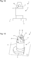
- FIGS. Figures 1A and 1B annexed to this patent application.
- the peak 2 comprises a base 4 which extends in a plane P on which stand a first arm 6 and a second arm 8 which are free at their end opposite to the base 4.
- the first and second arms 6 and 8 extend perpendicularly to the plane P of the base 4 and are separated from each other by a substantially parallelepipedal gap 10.
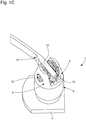
- the stud 2 is provided with a stop means provided to prevent a glue pad 16 in which is trapped a free end 18 of a last turn on the outside of a spiral spring 20 to escape from the gap 10 in the case where the glue pad 16 separates from the piton 2.
- this stop means is in the form of a hole 22 pierced right through in at least one of the first and second arms 6, 8. In the example illustrated in FIGS. Figures 1A, 1B a hole 22 is drilled in each of the two arms 6 and 8.
- spiral spring 20 made of silicon more particularly visible on the Figures 6A and 6B is conventionally made of a very thin spring wound in concentric turns and whose section is constant over substantially its entire length.
- This spiral spring 20 is fixed via a free end 24 of a first turn inside to a balance shaft of the watch movement (not shown) for example by means of a ferrule 28, and via the free end 18 of its last turn outside at piton 2 according to the invention.
- the last turn outside the spiral spring 20 slightly thicker than the other turns over part of its length, can be provided at its free end 18 with a plate 30 made in one piece with the spiral spring 20.
- the presence of the wafer 30 is dictated by considerations specific to the technique of manufacturing spiral springs 20 in silicon only. It is important to understand that the presence of this plate 30 is not made necessary by the needs of the present invention and that it is quite possible to fix a spiral spring without such a plate on the stud 2 according to the invention.
- a hole 22 is pierced right through each of the two arms 6 and 8.
- the liquid adhesive when the liquid adhesive is deposited in the gap 10, the latter diffuses into the holes 22 by capillarity, holes 22 in which the liquid glue will remain trapped and harden after exposure by means of UV radiation or in contact with air. It thus forms an adhesive pad 16 in which the free end 18 of the last turn outside the spiral spring 20 is found imprisoned. Therefore, if, during the life of the glue pad 16 comes to separate or peel off the piton 2, it will not succeed however in disengaging itself from the gap 10 in which it is housed and decoupled from the piton 2 according to the invention, so that it will not interfere with the operation of the watch movement. Indeed, the glue pad 16 will not be able to disengage from the gap 10, especially in the region where the liquid glue has hardened in the holes 22.
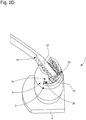
- FIGS. FIGS. 2A to 2C Designated as a whole by the general numerical reference 36, a second particular embodiment of a stud 2 according to the invention is shown in FIGS. FIGS. 2A to 2C annexed to this patent application.
- a groove 38 which extends in a plane which forms an angle with the plane P of the base 4 is machined in at least one of the first and second arms 6, 8.
- a groove 38 is machined in the two arms 6 and 8 and extends in a plane perpendicular to the plane P of the base.
- the groove 38 defines for each of the first and second arms 6 and 8 a hook 40 which, once the glue pad 16 cured for example by exposure by means of UV radiation or in contact with the air, will retain the resulting glue pad 16 and prevent it from emerging from the gap 10 in the case where the glue pad 16 disengages the pin 2.
- the hooks 40 form two bearing surfaces 42 on which the liquid adhesive will be deposited by capillarity before curing to form the adhesive pad 16 and which will prevent any possible withdrawal of the adhesive pad 16.
- the 2D figure is a view similar to those of FIGS. 2A to 2C on which we see the spiral spring 20 in silicon fixed on the stud 2 by the free end 18 of its last turn outside by means of an adhesive pad 16.
- FIG. figure 3A Designated as a whole by the general numerical reference 44, a third particular embodiment of a stud 2 according to the invention is shown in FIG. figure 3A attached to this patent application.
- the stop means protrudes into the gap 10 provided for receiving the hardened adhesive pad 16 in which the free end 18 of the last turn is trapped.
- the stop means is in the form of a bead 46 coming from a material with each of the inner lateral surfaces 48 facing each other from the first and second ends. second arm 6 and 8.
- the figure 3B is a view similar to that of the figure 3A on which we see the spiral spring 20 silicon fixed by the free end 18 of its last turn outside on the stud 2 by means of an adhesive pad 16.
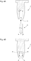
- FIGS. Figures 4A and 4B A possible technique for making the beads 46 is illustrated in FIGS. Figures 4A and 4B .
- This technique consists in providing a stud 2 having a gap 10 whose initial width is d1 , then introducing into this gap 10 a stamping tool 50 whose width d2 is greater than the width d1 and corresponds to the final width of the gap 10 sought. Forcing the stamping tool 50 in the gap 10, the material is forced back and is created on each of the inner side surfaces 48 of the first and second arms 6, 8 a bead 46.
- the beads 46 correspond to a preferred but non-limiting embodiment of the invention. Indeed, to obtain a stop means projecting into the gap 10, it can also be envisaged, for example, to pierce through at least one of the two arms 6, 8, and then introduce into the hole thus obtained a pin which projects into the gap 10.
- FIGS. Figures 5A to 5D Another possible technique for creating an annular flange 52 is illustrated in FIGS. Figures 5A to 5D .
- This technique consists in providing a stud 2 having a gap 10, then introducing into this gap 10 a drilling tool 54 whose end is conical. By advancing the drilling tool 54 in the gap 10 from the free end of the arms 6, 8 to the base 4, a first hole 56 is created in the bolt 2 ( Figure 5A ). Conversely, a second hole 58 is machined in the stud 2 from the base 4 towards the free end of the first and second arms 6, 8 ( Figure 5B ).
- the machining is carried out so that the second hole 58 partially opens into the first hole 56, while retaining locally an annular flange 52 on the inner lateral surfaces 48 of the first and second arms 6 and 8 ( Figure 5C ).
- the latter is hardened so as to form a glue pad 16 ( Figure 6D ).
- the glue stud 16 thus formed is retained by the annular collar 52, so that even if the stud 16 is detached from the stud 2, it will be retained inside the gap 10 from which it can not escape. .
- This drop of liquid adhesive 32 is for example deposited by means of a dispensing device 60 automated such as a syringe still known by its English name "dispenser".
- a dispensing device 60 automated such as a syringe still known by its English name "dispenser”.
- the exposure of the drop of liquid glue 32 to ultraviolet light allows its polymerization and its complete hardening.
- the example of the polymerizable liquid glue by exposure to ultraviolet light is given by way of example only, and that other types of liquid glues such as a glue hardening in contact with the air can be envisaged. .
Landscapes
- Physics & Mathematics (AREA)
- General Physics & Mathematics (AREA)
- Springs (AREA)
- Standing Axle, Rod, Or Tube Structures Coupled By Welding, Adhesion, Or Deposition (AREA)
- Adornments (AREA)
Priority Applications (4)
| Application Number | Priority Date | Filing Date | Title |
|---|---|---|---|
| EP18172195.2A EP3570118B1 (de) | 2018-05-14 | 2018-05-14 | Spiralklötzchen für die befestigung einer spiralfeder eines uhrwerks, und herstellungsverfahren eines solchen spiralklötzchens |
| JP2019065797A JP6892888B2 (ja) | 2018-05-14 | 2019-03-29 | 計時器用ムーブメントの渦巻き状のばねを固定するバランスばねスタッド及びこのようなバランスばねスタッドを製造する方法 |
| US16/379,009 US11480926B2 (en) | 2018-05-14 | 2019-04-09 | Balance-spring stud for fixing a spiral spring of a timepiece movement and method for manufacturing such a balance-spring stud |
| CN201910393205.3A CN110488592B (zh) | 2018-05-14 | 2019-05-13 | 游丝外桩和用于制造游丝外桩的方法 |
Applications Claiming Priority (1)
| Application Number | Priority Date | Filing Date | Title |
|---|---|---|---|
| EP18172195.2A EP3570118B1 (de) | 2018-05-14 | 2018-05-14 | Spiralklötzchen für die befestigung einer spiralfeder eines uhrwerks, und herstellungsverfahren eines solchen spiralklötzchens |
Publications (2)
| Publication Number | Publication Date |
|---|---|
| EP3570118A1 true EP3570118A1 (de) | 2019-11-20 |
| EP3570118B1 EP3570118B1 (de) | 2022-01-12 |
Family
ID=62167150
Family Applications (1)
| Application Number | Title | Priority Date | Filing Date |
|---|---|---|---|
| EP18172195.2A Active EP3570118B1 (de) | 2018-05-14 | 2018-05-14 | Spiralklötzchen für die befestigung einer spiralfeder eines uhrwerks, und herstellungsverfahren eines solchen spiralklötzchens |
Country Status (4)
| Country | Link |
|---|---|
| US (1) | US11480926B2 (de) |
| EP (1) | EP3570118B1 (de) |
| JP (1) | JP6892888B2 (de) |
| CN (1) | CN110488592B (de) |
Cited By (3)
| Publication number | Priority date | Publication date | Assignee | Title |
|---|---|---|---|---|
| EP4386490A1 (de) * | 2022-12-13 | 2024-06-19 | The Swatch Group Research and Development Ltd | Uhrkomponente, die aus der verbindung zweier teile erzeugt wird, und verfahren zur herstellung der komponente |
| CH720429A1 (fr) * | 2023-01-12 | 2024-07-31 | Vaucher Mft Fleurier S A | Ensemble piton-spiral pour mouvement d'horlogerie |
| EP4481507A1 (de) * | 2023-06-22 | 2024-12-25 | Seiko Epson Corporation | Spiralklötchen, spiralfeder mit spiralklötchen und herstellungsverfahren dafür, unruh mit spiralfeder und uhr |
Families Citing this family (3)
| Publication number | Priority date | Publication date | Assignee | Title |
|---|---|---|---|---|
| JP6757481B1 (ja) * | 2020-01-29 | 2020-09-16 | セイコーウオッチ株式会社 | 調速機、脱進機、ムーブメント及び時計 |
| EP4332686A1 (de) | 2022-08-30 | 2024-03-06 | ETA SA Manufacture Horlogère Suisse | Spiralfeder für eine spiralunruh-einheit einer uhrwerke |
| EP4498175A1 (de) * | 2023-07-24 | 2025-01-29 | ETA SA Manufacture Horlogère Suisse | Uhreinstellorgan mit hakenbetätigungssystem |
Citations (3)
| Publication number | Priority date | Publication date | Assignee | Title |
|---|---|---|---|---|
| FR2051170A5 (de) * | 1969-06-26 | 1971-04-02 | Kienzle Uhrenfabriken Gmbh | |
| FR2352332A1 (fr) * | 1975-12-02 | 1977-12-16 | Hormec Sa | Dispositif de fixation de l'extremite exterieure d'un spiral d'horlogerie |
| CH622149GA3 (en) * | 1977-12-23 | 1981-03-31 | Device for fixing the outer end of a hairspring to the framework of the movement of a timepiece and method for manufacturing this device |
Family Cites Families (10)
| Publication number | Priority date | Publication date | Assignee | Title |
|---|---|---|---|---|
| CH499804A (fr) * | 1965-04-21 | 1969-04-15 | Virola Sa | Dispositif de fixation d'un spiral d'horlogerie à l'axe du balancier |
| FR2141622B1 (de) * | 1971-06-15 | 1977-06-03 | Lip Horlogerie | |
| CH45273A4 (de) * | 1973-01-12 | 1974-09-13 | ||
| FR2283475A1 (fr) * | 1973-12-21 | 1976-03-26 | Epsilon Sarl | Procede pour la fixation de l'extremite exterieure d'un ressort spiral a un piton et piton pour la mise en oeuvre du procede |
| JPS521172U (de) * | 1975-06-23 | 1977-01-06 | ||
| WO1999012080A1 (en) * | 1997-08-28 | 1999-03-11 | Seiko Epson Corporation | Spring, power spring, hair spring, driving mechanism utilizing them, and timepiece |
| EP1515200A1 (de) * | 2003-09-10 | 2005-03-16 | Patek Philippe S.A. | Spiralfeder für Uhren |
| EP3118692B1 (de) * | 2015-07-16 | 2018-12-26 | Nivarox-FAR S.A. | Befestigung der spiralfeder eines uhrwerks durch verklebung |
| EP3211486B1 (de) * | 2016-02-25 | 2018-09-26 | ETA SA Manufacture Horlogère Suisse | Befestigungsverfahren einer spiralfeder für ein mechanisches uhrwerk |
| CH711473B1 (fr) * | 2016-02-25 | 2017-03-15 | Eta Sa Mft Horlogère Suisse | Procédé de fixation d'un spiral pour mouvement d'horlogerie mécanique au moyen d'une colle dans un piton. |
-
2018
- 2018-05-14 EP EP18172195.2A patent/EP3570118B1/de active Active
-
2019
- 2019-03-29 JP JP2019065797A patent/JP6892888B2/ja active Active
- 2019-04-09 US US16/379,009 patent/US11480926B2/en active Active
- 2019-05-13 CN CN201910393205.3A patent/CN110488592B/zh active Active
Patent Citations (3)
| Publication number | Priority date | Publication date | Assignee | Title |
|---|---|---|---|---|
| FR2051170A5 (de) * | 1969-06-26 | 1971-04-02 | Kienzle Uhrenfabriken Gmbh | |
| FR2352332A1 (fr) * | 1975-12-02 | 1977-12-16 | Hormec Sa | Dispositif de fixation de l'extremite exterieure d'un spiral d'horlogerie |
| CH622149GA3 (en) * | 1977-12-23 | 1981-03-31 | Device for fixing the outer end of a hairspring to the framework of the movement of a timepiece and method for manufacturing this device |
Cited By (4)
| Publication number | Priority date | Publication date | Assignee | Title |
|---|---|---|---|---|
| EP4386490A1 (de) * | 2022-12-13 | 2024-06-19 | The Swatch Group Research and Development Ltd | Uhrkomponente, die aus der verbindung zweier teile erzeugt wird, und verfahren zur herstellung der komponente |
| US12613495B2 (en) | 2022-12-13 | 2026-04-28 | The Swatch Group Research And Development Ltd | Horological component resulting from the assembly of two parts and method for manufacturing said component |
| CH720429A1 (fr) * | 2023-01-12 | 2024-07-31 | Vaucher Mft Fleurier S A | Ensemble piton-spiral pour mouvement d'horlogerie |
| EP4481507A1 (de) * | 2023-06-22 | 2024-12-25 | Seiko Epson Corporation | Spiralklötchen, spiralfeder mit spiralklötchen und herstellungsverfahren dafür, unruh mit spiralfeder und uhr |
Also Published As
| Publication number | Publication date |
|---|---|
| CN110488592B (zh) | 2021-03-16 |
| CN110488592A (zh) | 2019-11-22 |
| JP2019200199A (ja) | 2019-11-21 |
| EP3570118B1 (de) | 2022-01-12 |
| US11480926B2 (en) | 2022-10-25 |
| JP6892888B2 (ja) | 2021-06-23 |
| US20190346812A1 (en) | 2019-11-14 |
Similar Documents
| Publication | Publication Date | Title |
|---|---|---|
| EP3570118B1 (de) | Spiralklötzchen für die befestigung einer spiralfeder eines uhrwerks, und herstellungsverfahren eines solchen spiralklötzchens | |
| EP2196868B1 (de) | Spirale mit Kurvenerhöhung aus Material auf Siliziumbasis | |
| EP2184652B1 (de) | Spiralfeder mit Endkurvenerhöhung aus mikro-bearbeitbarem Material | |
| EP1035453A1 (de) | Zifferblatt für Uhren mit Brillanten, Auflegestücken oder anderen eingesetzen Elementen und Verfahren zur Befestigung dieser Elemente an einem solchen Zifferblatt | |
| EP3182212B1 (de) | Verbundwerkstück mit unter spannung stehenden elastischen mitteln | |
| EP2930571A1 (de) | Uhreneinstellung, die ein amorphen Metal verwendet | |
| EP2469351A1 (de) | Zusammenbau eines Teils, das keinen Plastikbereich enthält | |
| EP2154582A1 (de) | Verzahnungverfahren für Uhrwerk | |
| EP2206022B1 (de) | Stossdämpfende lagerung für eine uhr | |
| CH714775B1 (fr) | Piton pour la fixation d'un ressort spiral d'un mouvement d'horlogerie et procédés de fabrication d'un tel piton. | |
| EP2585877B1 (de) | Verfahren zur herstellung einer zumindest zweiteiligen komponente zur fertigung einer uhr | |
| EP2107433B1 (de) | Montageverfahren eines Bauteils auf eine Welle | |
| EP3430480B1 (de) | Verfahren zum zusammenbau einer vorrichtung, die mindestens aus zwei teilen besteht | |
| CH699147B1 (fr) | Procédé de fixation d'un flanc transparent sur un mobile métallique. | |
| EP4332687A1 (de) | Spiralfeder einer unruh-spiralfeder einer mechanischen uhr | |
| CH710113B1 (fr) | Composant mécanique, procédé de fabrication d'un composant mécanique, mouvement et pièce d'horlogerie. | |
| EP4372480B1 (de) | Uhranordnung mit spiralfeder und stepper | |
| EP1211578B1 (de) | Zusammenbau einer elektromagnetischen Vorrichtung durch Stapeln mehrerer Module, insbesondere für ein äusserst dünnes Uhrwerk | |
| CH704275A1 (fr) | Bascule pour un echappement dit a force constante d'une piece d'horlogerie. | |
| EP4394523A1 (de) | Teil zur befestigung einer der letzten windungen an der aussenseite einer spiralfeder einer uhrwerke | |
| CH719838B1 (fr) | Pièce de fixation d'un ressort spiral d'un mouvement d'horlogerie. | |
| EP3185085B1 (de) | Applique für zifferblatt einer uhr | |
| CH719711B1 (fr) | Ensemble horloger comprenant un ressort spiral et un piton | |
| CH711473B1 (fr) | Procédé de fixation d'un spiral pour mouvement d'horlogerie mécanique au moyen d'une colle dans un piton. | |
| CH719727B1 (fr) | Spiral d'un ensemble balancier-spiral d'un mouvement d'horlogerie mécanique. |
Legal Events
| Date | Code | Title | Description |
|---|---|---|---|
| PUAI | Public reference made under article 153(3) epc to a published international application that has entered the european phase |
Free format text: ORIGINAL CODE: 0009012 |
|
| STAA | Information on the status of an ep patent application or granted ep patent |
Free format text: STATUS: THE APPLICATION HAS BEEN PUBLISHED |
|
| AK | Designated contracting states |
Kind code of ref document: A1 Designated state(s): AL AT BE BG CH CY CZ DE DK EE ES FI FR GB GR HR HU IE IS IT LI LT LU LV MC MK MT NL NO PL PT RO RS SE SI SK SM TR |
|
| AX | Request for extension of the european patent |
Extension state: BA ME |
|
| STAA | Information on the status of an ep patent application or granted ep patent |
Free format text: STATUS: REQUEST FOR EXAMINATION WAS MADE |
|
| 17P | Request for examination filed |
Effective date: 20200520 |
|
| RBV | Designated contracting states (corrected) |
Designated state(s): AL AT BE BG CH CY CZ DE DK EE ES FI FR GB GR HR HU IE IS IT LI LT LU LV MC MK MT NL NO PL PT RO RS SE SI SK SM TR |
|
| GRAP | Despatch of communication of intention to grant a patent |
Free format text: ORIGINAL CODE: EPIDOSNIGR1 |
|
| STAA | Information on the status of an ep patent application or granted ep patent |
Free format text: STATUS: GRANT OF PATENT IS INTENDED |
|
| INTG | Intention to grant announced |
Effective date: 20210728 |
|
| GRAS | Grant fee paid |
Free format text: ORIGINAL CODE: EPIDOSNIGR3 |
|
| GRAJ | Information related to disapproval of communication of intention to grant by the applicant or resumption of examination proceedings by the epo deleted |
Free format text: ORIGINAL CODE: EPIDOSDIGR1 |
|
| GRAL | Information related to payment of fee for publishing/printing deleted |
Free format text: ORIGINAL CODE: EPIDOSDIGR3 |
|
| STAA | Information on the status of an ep patent application or granted ep patent |
Free format text: STATUS: REQUEST FOR EXAMINATION WAS MADE |
|
| INTC | Intention to grant announced (deleted) | ||
| GRAP | Despatch of communication of intention to grant a patent |
Free format text: ORIGINAL CODE: EPIDOSNIGR1 |
|
| STAA | Information on the status of an ep patent application or granted ep patent |
Free format text: STATUS: GRANT OF PATENT IS INTENDED |
|
| GRAA | (expected) grant |
Free format text: ORIGINAL CODE: 0009210 |
|
| STAA | Information on the status of an ep patent application or granted ep patent |
Free format text: STATUS: THE PATENT HAS BEEN GRANTED |
|
| INTG | Intention to grant announced |
Effective date: 20211130 |
|
| AK | Designated contracting states |
Kind code of ref document: B1 Designated state(s): AL AT BE BG CH CY CZ DE DK EE ES FI FR GB GR HR HU IE IS IT LI LT LU LV MC MK MT NL NO PL PT RO RS SE SI SK SM TR |
|
| REG | Reference to a national code |
Ref country code: GB Ref legal event code: FG4D Free format text: NOT ENGLISH |
|
| REG | Reference to a national code |
Ref country code: CH Ref legal event code: EP |
|
| REG | Reference to a national code |
Ref country code: DE Ref legal event code: R096 Ref document number: 602018029426 Country of ref document: DE |
|
| REG | Reference to a national code |
Ref country code: IE Ref legal event code: FG4D Free format text: LANGUAGE OF EP DOCUMENT: FRENCH |
|
| REG | Reference to a national code |
Ref country code: AT Ref legal event code: REF Ref document number: 1462794 Country of ref document: AT Kind code of ref document: T Effective date: 20220215 |
|
| REG | Reference to a national code |
Ref country code: LT Ref legal event code: MG9D |
|
| REG | Reference to a national code |
Ref country code: NL Ref legal event code: MP Effective date: 20220112 |
|
| REG | Reference to a national code |
Ref country code: AT Ref legal event code: MK05 Ref document number: 1462794 Country of ref document: AT Kind code of ref document: T Effective date: 20220112 |
|
| PG25 | Lapsed in a contracting state [announced via postgrant information from national office to epo] |
Ref country code: NL Free format text: LAPSE BECAUSE OF FAILURE TO SUBMIT A TRANSLATION OF THE DESCRIPTION OR TO PAY THE FEE WITHIN THE PRESCRIBED TIME-LIMIT Effective date: 20220112 |
|
| PG25 | Lapsed in a contracting state [announced via postgrant information from national office to epo] |
Ref country code: SE Free format text: LAPSE BECAUSE OF FAILURE TO SUBMIT A TRANSLATION OF THE DESCRIPTION OR TO PAY THE FEE WITHIN THE PRESCRIBED TIME-LIMIT Effective date: 20220112 Ref country code: RS Free format text: LAPSE BECAUSE OF FAILURE TO SUBMIT A TRANSLATION OF THE DESCRIPTION OR TO PAY THE FEE WITHIN THE PRESCRIBED TIME-LIMIT Effective date: 20220112 Ref country code: PT Free format text: LAPSE BECAUSE OF FAILURE TO SUBMIT A TRANSLATION OF THE DESCRIPTION OR TO PAY THE FEE WITHIN THE PRESCRIBED TIME-LIMIT Effective date: 20220512 Ref country code: NO Free format text: LAPSE BECAUSE OF FAILURE TO SUBMIT A TRANSLATION OF THE DESCRIPTION OR TO PAY THE FEE WITHIN THE PRESCRIBED TIME-LIMIT Effective date: 20220412 Ref country code: LT Free format text: LAPSE BECAUSE OF FAILURE TO SUBMIT A TRANSLATION OF THE DESCRIPTION OR TO PAY THE FEE WITHIN THE PRESCRIBED TIME-LIMIT Effective date: 20220112 Ref country code: HR Free format text: LAPSE BECAUSE OF FAILURE TO SUBMIT A TRANSLATION OF THE DESCRIPTION OR TO PAY THE FEE WITHIN THE PRESCRIBED TIME-LIMIT Effective date: 20220112 Ref country code: ES Free format text: LAPSE BECAUSE OF FAILURE TO SUBMIT A TRANSLATION OF THE DESCRIPTION OR TO PAY THE FEE WITHIN THE PRESCRIBED TIME-LIMIT Effective date: 20220112 Ref country code: BG Free format text: LAPSE BECAUSE OF FAILURE TO SUBMIT A TRANSLATION OF THE DESCRIPTION OR TO PAY THE FEE WITHIN THE PRESCRIBED TIME-LIMIT Effective date: 20220412 |
|
| PG25 | Lapsed in a contracting state [announced via postgrant information from national office to epo] |
Ref country code: PL Free format text: LAPSE BECAUSE OF FAILURE TO SUBMIT A TRANSLATION OF THE DESCRIPTION OR TO PAY THE FEE WITHIN THE PRESCRIBED TIME-LIMIT Effective date: 20220112 Ref country code: LV Free format text: LAPSE BECAUSE OF FAILURE TO SUBMIT A TRANSLATION OF THE DESCRIPTION OR TO PAY THE FEE WITHIN THE PRESCRIBED TIME-LIMIT Effective date: 20220112 Ref country code: GR Free format text: LAPSE BECAUSE OF FAILURE TO SUBMIT A TRANSLATION OF THE DESCRIPTION OR TO PAY THE FEE WITHIN THE PRESCRIBED TIME-LIMIT Effective date: 20220413 Ref country code: FI Free format text: LAPSE BECAUSE OF FAILURE TO SUBMIT A TRANSLATION OF THE DESCRIPTION OR TO PAY THE FEE WITHIN THE PRESCRIBED TIME-LIMIT Effective date: 20220112 Ref country code: AT Free format text: LAPSE BECAUSE OF FAILURE TO SUBMIT A TRANSLATION OF THE DESCRIPTION OR TO PAY THE FEE WITHIN THE PRESCRIBED TIME-LIMIT Effective date: 20220112 |
|
| PG25 | Lapsed in a contracting state [announced via postgrant information from national office to epo] |
Ref country code: IS Free format text: LAPSE BECAUSE OF FAILURE TO SUBMIT A TRANSLATION OF THE DESCRIPTION OR TO PAY THE FEE WITHIN THE PRESCRIBED TIME-LIMIT Effective date: 20220512 |
|
| REG | Reference to a national code |
Ref country code: DE Ref legal event code: R097 Ref document number: 602018029426 Country of ref document: DE |
|
| PG25 | Lapsed in a contracting state [announced via postgrant information from national office to epo] |
Ref country code: SM Free format text: LAPSE BECAUSE OF FAILURE TO SUBMIT A TRANSLATION OF THE DESCRIPTION OR TO PAY THE FEE WITHIN THE PRESCRIBED TIME-LIMIT Effective date: 20220112 Ref country code: SK Free format text: LAPSE BECAUSE OF FAILURE TO SUBMIT A TRANSLATION OF THE DESCRIPTION OR TO PAY THE FEE WITHIN THE PRESCRIBED TIME-LIMIT Effective date: 20220112 Ref country code: RO Free format text: LAPSE BECAUSE OF FAILURE TO SUBMIT A TRANSLATION OF THE DESCRIPTION OR TO PAY THE FEE WITHIN THE PRESCRIBED TIME-LIMIT Effective date: 20220112 Ref country code: EE Free format text: LAPSE BECAUSE OF FAILURE TO SUBMIT A TRANSLATION OF THE DESCRIPTION OR TO PAY THE FEE WITHIN THE PRESCRIBED TIME-LIMIT Effective date: 20220112 Ref country code: DK Free format text: LAPSE BECAUSE OF FAILURE TO SUBMIT A TRANSLATION OF THE DESCRIPTION OR TO PAY THE FEE WITHIN THE PRESCRIBED TIME-LIMIT Effective date: 20220112 Ref country code: CZ Free format text: LAPSE BECAUSE OF FAILURE TO SUBMIT A TRANSLATION OF THE DESCRIPTION OR TO PAY THE FEE WITHIN THE PRESCRIBED TIME-LIMIT Effective date: 20220112 |
|
| PLBE | No opposition filed within time limit |
Free format text: ORIGINAL CODE: 0009261 |
|
| STAA | Information on the status of an ep patent application or granted ep patent |
Free format text: STATUS: NO OPPOSITION FILED WITHIN TIME LIMIT |
|
| PG25 | Lapsed in a contracting state [announced via postgrant information from national office to epo] |
Ref country code: AL Free format text: LAPSE BECAUSE OF FAILURE TO SUBMIT A TRANSLATION OF THE DESCRIPTION OR TO PAY THE FEE WITHIN THE PRESCRIBED TIME-LIMIT Effective date: 20220112 |
|
| 26N | No opposition filed |
Effective date: 20221013 |
|
| REG | Reference to a national code |
Ref country code: BE Ref legal event code: MM Effective date: 20220531 |
|
| PG25 | Lapsed in a contracting state [announced via postgrant information from national office to epo] |
Ref country code: MC Free format text: LAPSE BECAUSE OF FAILURE TO SUBMIT A TRANSLATION OF THE DESCRIPTION OR TO PAY THE FEE WITHIN THE PRESCRIBED TIME-LIMIT Effective date: 20220112 Ref country code: LU Free format text: LAPSE BECAUSE OF NON-PAYMENT OF DUE FEES Effective date: 20220514 |
|
| PG25 | Lapsed in a contracting state [announced via postgrant information from national office to epo] |
Ref country code: SI Free format text: LAPSE BECAUSE OF FAILURE TO SUBMIT A TRANSLATION OF THE DESCRIPTION OR TO PAY THE FEE WITHIN THE PRESCRIBED TIME-LIMIT Effective date: 20220112 |
|
| PG25 | Lapsed in a contracting state [announced via postgrant information from national office to epo] |
Ref country code: IE Free format text: LAPSE BECAUSE OF NON-PAYMENT OF DUE FEES Effective date: 20220514 |
|
| PG25 | Lapsed in a contracting state [announced via postgrant information from national office to epo] |
Ref country code: BE Free format text: LAPSE BECAUSE OF NON-PAYMENT OF DUE FEES Effective date: 20220531 |
|
| PG25 | Lapsed in a contracting state [announced via postgrant information from national office to epo] |
Ref country code: IT Free format text: LAPSE BECAUSE OF FAILURE TO SUBMIT A TRANSLATION OF THE DESCRIPTION OR TO PAY THE FEE WITHIN THE PRESCRIBED TIME-LIMIT Effective date: 20220112 |
|
| P01 | Opt-out of the competence of the unified patent court (upc) registered |
Effective date: 20230701 |
|
| PG25 | Lapsed in a contracting state [announced via postgrant information from national office to epo] |
Ref country code: HU Free format text: LAPSE BECAUSE OF FAILURE TO SUBMIT A TRANSLATION OF THE DESCRIPTION OR TO PAY THE FEE WITHIN THE PRESCRIBED TIME-LIMIT; INVALID AB INITIO Effective date: 20180514 |
|
| PG25 | Lapsed in a contracting state [announced via postgrant information from national office to epo] |
Ref country code: MK Free format text: LAPSE BECAUSE OF FAILURE TO SUBMIT A TRANSLATION OF THE DESCRIPTION OR TO PAY THE FEE WITHIN THE PRESCRIBED TIME-LIMIT Effective date: 20220112 Ref country code: CY Free format text: LAPSE BECAUSE OF FAILURE TO SUBMIT A TRANSLATION OF THE DESCRIPTION OR TO PAY THE FEE WITHIN THE PRESCRIBED TIME-LIMIT Effective date: 20220112 |
|
| PG25 | Lapsed in a contracting state [announced via postgrant information from national office to epo] |
Ref country code: TR Free format text: LAPSE BECAUSE OF FAILURE TO SUBMIT A TRANSLATION OF THE DESCRIPTION OR TO PAY THE FEE WITHIN THE PRESCRIBED TIME-LIMIT Effective date: 20220112 |
|
| PG25 | Lapsed in a contracting state [announced via postgrant information from national office to epo] |
Ref country code: MT Free format text: LAPSE BECAUSE OF FAILURE TO SUBMIT A TRANSLATION OF THE DESCRIPTION OR TO PAY THE FEE WITHIN THE PRESCRIBED TIME-LIMIT Effective date: 20220112 |
|
| PGFP | Annual fee paid to national office [announced via postgrant information from national office to epo] |
Ref country code: DE Payment date: 20250423 Year of fee payment: 8 |
|
| PGFP | Annual fee paid to national office [announced via postgrant information from national office to epo] |
Ref country code: GB Payment date: 20250423 Year of fee payment: 8 |
|
| PGFP | Annual fee paid to national office [announced via postgrant information from national office to epo] |
Ref country code: FR Payment date: 20250423 Year of fee payment: 8 |
|
| PGFP | Annual fee paid to national office [announced via postgrant information from national office to epo] |
Ref country code: CH Payment date: 20250601 Year of fee payment: 8 |