EP3571138B1 - Système de distribution de milieu fluide et procédé d'assemblage d'un système de distribution destiné à un milieu fluide - Google Patents
Système de distribution de milieu fluide et procédé d'assemblage d'un système de distribution destiné à un milieu fluide Download PDFInfo
- Publication number
- EP3571138B1 EP3571138B1 EP17701441.2A EP17701441A EP3571138B1 EP 3571138 B1 EP3571138 B1 EP 3571138B1 EP 17701441 A EP17701441 A EP 17701441A EP 3571138 B1 EP3571138 B1 EP 3571138B1
- Authority
- EP
- European Patent Office
- Prior art keywords
- container
- valve cup
- neck
- valve
- opening
- Prior art date
- Legal status (The legal status is an assumption and is not a legal conclusion. Google has not performed a legal analysis and makes no representation as to the accuracy of the status listed.)
- Active
Links
Images

Classifications
-
- B—PERFORMING OPERATIONS; TRANSPORTING
- B65—CONVEYING; PACKING; STORING; HANDLING THIN OR FILAMENTARY MATERIAL
- B65D—CONTAINERS FOR STORAGE OR TRANSPORT OF ARTICLES OR MATERIALS, e.g. BAGS, BARRELS, BOTTLES, BOXES, CANS, CARTONS, CRATES, DRUMS, JARS, TANKS, HOPPERS, FORWARDING CONTAINERS; ACCESSORIES, CLOSURES, OR FITTINGS THEREFOR; PACKAGING ELEMENTS; PACKAGES
- B65D83/00—Containers or packages with special means for dispensing contents
- B65D83/14—Containers for dispensing liquid or semi-liquid contents by internal gaseous pressure, i.e. aerosol containers comprising propellant
- B65D83/38—Details of the container body
-
- B—PERFORMING OPERATIONS; TRANSPORTING
- B65—CONVEYING; PACKING; STORING; HANDLING THIN OR FILAMENTARY MATERIAL
- B65D—CONTAINERS FOR STORAGE OR TRANSPORT OF ARTICLES OR MATERIALS, e.g. BAGS, BARRELS, BOTTLES, BOXES, CANS, CARTONS, CRATES, DRUMS, JARS, TANKS, HOPPERS, FORWARDING CONTAINERS; ACCESSORIES, CLOSURES, OR FITTINGS THEREFOR; PACKAGING ELEMENTS; PACKAGES
- B65D83/00—Containers or packages with special means for dispensing contents
- B65D83/14—Containers for dispensing liquid or semi-liquid contents by internal gaseous pressure, i.e. aerosol containers comprising propellant
- B65D83/60—Containers for dispensing liquid or semi-liquid contents by internal gaseous pressure, i.e. aerosol containers comprising propellant with contents and propellant separated
- B65D83/62—Containers for dispensing liquid or semi-liquid contents by internal gaseous pressure, i.e. aerosol containers comprising propellant with contents and propellant separated by membranes, bags or the like
-
- B—PERFORMING OPERATIONS; TRANSPORTING
- B29—WORKING OF PLASTICS; WORKING OF SUBSTANCES IN A PLASTIC STATE IN GENERAL
- B29C—SHAPING OR JOINING OF PLASTICS; SHAPING OF MATERIAL IN A PLASTIC STATE, NOT OTHERWISE PROVIDED FOR; AFTER-TREATMENT OF THE SHAPED PRODUCTS, e.g. REPAIRING
- B29C2949/00—Indexing scheme relating to blow-moulding
- B29C2949/07—Preforms or parisons characterised by their configuration
- B29C2949/076—Preforms or parisons characterised by their configuration characterised by the shape
- B29C2949/0768—Preforms or parisons characterised by their configuration characterised by the shape characterised by the shape of specific parts of preform
- B29C2949/0769—Preforms or parisons characterised by their configuration characterised by the shape characterised by the shape of specific parts of preform characterised by the lip, i.e. very top of preform neck
-
- B—PERFORMING OPERATIONS; TRANSPORTING
- B29—WORKING OF PLASTICS; WORKING OF SUBSTANCES IN A PLASTIC STATE IN GENERAL
- B29C—SHAPING OR JOINING OF PLASTICS; SHAPING OF MATERIAL IN A PLASTIC STATE, NOT OTHERWISE PROVIDED FOR; AFTER-TREATMENT OF THE SHAPED PRODUCTS, e.g. REPAIRING
- B29C2949/00—Indexing scheme relating to blow-moulding
- B29C2949/20—Preforms or parisons whereby a specific part is made of only one component, e.g. only one layer
- B29C2949/22—Preforms or parisons whereby a specific part is made of only one component, e.g. only one layer at neck portion
-
- B—PERFORMING OPERATIONS; TRANSPORTING
- B65—CONVEYING; PACKING; STORING; HANDLING THIN OR FILAMENTARY MATERIAL
- B65D—CONTAINERS FOR STORAGE OR TRANSPORT OF ARTICLES OR MATERIALS, e.g. BAGS, BARRELS, BOTTLES, BOXES, CANS, CARTONS, CRATES, DRUMS, JARS, TANKS, HOPPERS, FORWARDING CONTAINERS; ACCESSORIES, CLOSURES, OR FITTINGS THEREFOR; PACKAGING ELEMENTS; PACKAGES
- B65D83/00—Containers or packages with special means for dispensing contents
- B65D83/14—Containers for dispensing liquid or semi-liquid contents by internal gaseous pressure, i.e. aerosol containers comprising propellant
- B65D83/42—Filling or charging means
- B65D83/425—Delivery valves permitting filling or charging
-
- B—PERFORMING OPERATIONS; TRANSPORTING
- B65—CONVEYING; PACKING; STORING; HANDLING THIN OR FILAMENTARY MATERIAL
- B65D—CONTAINERS FOR STORAGE OR TRANSPORT OF ARTICLES OR MATERIALS, e.g. BAGS, BARRELS, BOTTLES, BOXES, CANS, CARTONS, CRATES, DRUMS, JARS, TANKS, HOPPERS, FORWARDING CONTAINERS; ACCESSORIES, CLOSURES, OR FITTINGS THEREFOR; PACKAGING ELEMENTS; PACKAGES
- B65D83/00—Containers or packages with special means for dispensing contents
- B65D83/14—Containers for dispensing liquid or semi-liquid contents by internal gaseous pressure, i.e. aerosol containers comprising propellant
- B65D83/44—Valves specially adapted for the discharge of contents; Regulating devices
- B65D83/48—Lift valves, e.g. operated by push action
-
- B—PERFORMING OPERATIONS; TRANSPORTING
- B65—CONVEYING; PACKING; STORING; HANDLING THIN OR FILAMENTARY MATERIAL
- B65D—CONTAINERS FOR STORAGE OR TRANSPORT OF ARTICLES OR MATERIALS, e.g. BAGS, BARRELS, BOTTLES, BOXES, CANS, CARTONS, CRATES, DRUMS, JARS, TANKS, HOPPERS, FORWARDING CONTAINERS; ACCESSORIES, CLOSURES, OR FITTINGS THEREFOR; PACKAGING ELEMENTS; PACKAGES
- B65D83/00—Containers or packages with special means for dispensing contents
- B65D83/14—Containers for dispensing liquid or semi-liquid contents by internal gaseous pressure, i.e. aerosol containers comprising propellant
- B65D83/68—Dispensing two or more contents
Definitions
- the present invention relates to an improvement in sealing performance and attachment between a valve cup and a container for dispensing a fluid medium stored under pressure and also to a method of assembling such a dispensing system for dispensing a fluid medium stored under pressure.
- Systems for dispensing a fluid medium stored under pressure are well-known and typically include a container, a valve, and a valve cup, wherein the valve cup supports the valve, usually centrally, and also closes off an opening of the container.
- the inner volume of the container is pressurized and maintained in such a state by the valve and seals between the valve cup and valve, and the valve cup and the container opening.
- the pressure difference between the inner volume of the container and the outside environment causes the fluid medium to be expelled from the container.
- Some systems employ a two-stage container having an inner and outer container, one of which contains the propellant gas, whereas others may employ a single container with the fluid medium also acting as the propellant.
- the containers are made from a metal, usually aluminium.
- PET polyethylene terephthalate
- PET containers also typically use a metal, e.g., aluminium, for the valve cups which ensures a suitable sealing engagement between the valve cup and valve.
- the valve cup may be clinched to a lip of the opening of the container. While the attachment between the valve cup and container is often sufficient at most normal operating temperatures, higher temperatures can cause the PET container to deform to a large degree such that the connection between the aluminium valve cup and container opening is no longer fluid tight. This is highly disadvantageous as the propellant gas and/or the fluid medium can escape from the container.
- a dispensing system exhibiting sufficient sealing performance at temperatures greater than 50°C is therefore required that enables the container and the valve cup to be made using plastics materials in order to take advantage of the considerable benefits of these materials.
- a fluid medium dispensing system comprising:
- valve cup to the neck of the container by a molten weld seam formed by laser welding not only secures the valve cup in position but also creates a seal that enables the dispensing system to withstand internal pressures of up to 13 bar.
- a seal has the advantage that it is simple and economical to employ.
- the plastics material of the neck of the container is laser-transparent and the plastics material of the valve cup is laser-absorbing.
- the laser welding of the valve cup to the neck of container involves passing a focused laser beam through the neck of the container to strike the interface between the neck and the valve cup. At the interface the laser light is turned into heat energy as it is absorbed by the plastics material of the valve cup. The heat created melts the plastics material at the interface in order to create the molten weld seam, which fuses the plastics materials of the valve cup and the neck together.
- Most thermoplastics transmit infrared laser radiation so laser light with a wavelength of either 980nm or 808nm is usually used as more energy is transmitted at these wavelengths. However, the plastics material of the valve cup must turn the light energy into heat and must therefore absorb the laser light.
- the plastics material of the valve cup is preferably laser-absorbing as opposed to laser-transparent.
- Additives are usually used to achieve this by providing light absorbing qualities. Most often carbon black is used, but many additives will promote absorption including various pigments and fills as will be known to those skilled in the art. It should also be noted that be that laser-transparent plastics material of the neck of the container can still be colored and even opaque if special non-absorbing colorants are used.
- the plastics material of the valve cup is a semi-crystalline polymer. It has been found that fully crystallized plastics materials tends to lose their shape during laser welding owing to the high temperatures reached. This is not the case when only semi-crystallized plastics material is used.
- Semi-crystalline polyesters have a greater degree of crystallinity when compared to more amorphous polyesters and they do not deform when exposed to temperatures greater than 50°C.
- Crystallized PET (CPET), PBT, PEN, and PEN/PET copolymers are or can be semi-crystalline polyesters. These materials are particularly advantageous for their other properties in packaging and not just their rigidity at elevated temperatures.
- any polyester that can be semi-crystalline and does not deform to a suitable degree at large temperatures may also be used as the semi-crystalline material.
- any blend of CPET, PBT, PEN, and PEN/PET may be used.
- the plastics material of the valve cup is selected from a group consisting of semi-crystallized PET, PBT, PEN, PEN/PET copolymers, POM, acrylonitrile, polypropylene, or a blend of any of the foregoing.
- the plastics material of the neck of the container is selected from a group consisting of: crystallized PET, PBT, PEN, PEN/PET copolymers, POM, acrylonitrile, polypropylene, or a blend of any of the foregoing.
- the whole of the valve cup is comprised of one or more laser-absorbing semi-crystalline polymers.
- the whole of the container is comprised of a laser-transparent plastics material.
- a method of assembling a dispensing system for dispensing a fluid medium stored under pressure including:
- a bag is attached to the valve such that its inner volume is in fluid communication with channels upstream and downstream of the valve when the valve is actuated and therefore open but is not in fluid communication with an interior volume of the container between the inside wall of the container and the outside surface of the bag.
- the bag contains the fluid medium to be dispensed by the system and the interior volume between the inside wall of the container and the outside surface of the bag contains a pressurized gas for use as a propellant.
- Bag-on-valve (BoV) packaging technologies are advantageously used for many consumer products, in particular for pharmaceutical and healthcare products. They have many advantages, in particular there is no need to use flammable propellants and they can be used with pressurized air or nitrogen. This is particularly important in the present invention as such a propellant will not have an adverse effect on the adhesive seal between the valve cup and the neck of the container.
- the method comprises the additional steps of providing a bag, attaching the valve to an opening of the bag, fluidly sealing the bag to the valve and inserting the bag into the container.
- the valve cup is an interference fit in the neck of the container with contact between said plastics materials of the valve cup and of the neck around the whole periphery of the valve cup. Such peripheral contact between the valve cup and the neck ensures that the molten weld seam formed during laser welding is secure around the totality of the opening in the neck that is closed by the valve cup.
- valve cup is pressed into the neck of the container during assembly with a force between 343 and 442 N, that is with a force between approximately 35 and 45 kg force.
- the valve cup comprises an inner part that is located in the opening of the container and the outer diameter of the inner part of the valve cup prior to pressing of the valve cup into the opening of the container is between 0.05 mm and 0.15 mm inclusive, and in particular 0.10 mm, greater than the inner diameter of the opening in order to create the interference fit.
- the molten weld seam is preferably located between the inner part of the valve cup that is pressed into the opening of the container and the neck of the container.
- the valve cup comprises an outer, annular part that defines a U-shape in which a rim of the neck of the container is located.
- the molten weld seam or an additional molten weld seam is preferably located between the rim of the neck of the container and the U-shaped, outer annular part of the valve cup.
- Plastic containers may be advantageous for various reasons when compared to metal containers, e.g., because of cost or ease of manufacturing.
- Polyesters, and in particular PET have many advantageous qualities in packaging applications. They can be easy to manipulate and thus forming containers of PET may be relatively easier and quicker than forming them of metal. In some cases, the polyesters may also be relatively cheap. Some polyesters can also be recycled thus reducing the overall overhead cost. Finally, some polyesters can also be sterilized which is particularly advantageous for medical applications.
- At least the neck of the container is preferably formed from a first plastics material, which is preferably a polyester.
- the container is formed from plastics material selected from a group consisting of: crystallized PET, PBT, PEN, PEN/PET copolymers, POM, acrylonitrile, polypropylene, or a blend of any of the foregoing.
- valve cup is either formed from a semi-crystalline polyester or includes a lining formed from a semi-crystalline polyester, which lining comprises the aforesaid portion of the valve cup that is contiguous with the neck of the container.
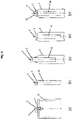
- Fig. 1 shows an example of a fluid medium dispensing system 1 in accordance with the present invention.
- the dispensing system 1 includes a valve cup 2, a container 3, and a valve 4.
- the inner region of the container 3 is pressurized to a pressure greater than atmospheric pressure.
- this pressure is typically around 7 bar although the pressure is not limited to this value and may take any desired value limited only by regional or governmental restrictions.
- the valve 4 is generally held in a fixed position by the valve cup 2 such that when a force is applied to the valve 4 by a user, the valve 4 is actuated to an open position. In this position, the pressure difference within and without the container 3 causes the fluid medium to be distributed from the container 3 via the valve 4.
- the valve 4 is not shown in any detail in the drawings as any suitable known valve can be used.
- the container 3 comprises a neck 5 defining an opening 6 in which the valve cup 2 is inserted.
- the neck 5 also includes a rim 7 that preferably comprises an annular lip 8.
- the valve cup 2 comprises a first, inner part 9 that is located in the opening 6 of the container 3 and a second, annular part 10 that covers the rim 7.
- the first part 9 is adapted to retain the valve 4 in a conventional manner and a plurality of strengthening ribs 11 may be provided located between the first and second parts 9 and 10.
- the first part 9 is an interference fit into the opening 6 of the neck 5 around the whole periphery of the first part 9.
- the outer diameter of the first part 9 and the diameter of the opening 6 are therefore predetermined in order to control the degree of force required to push-fit the first part of the valve cup 2 into the opening 6.
- the outer diameter of the inner part 9 is between 0.05 mm and 0.15 mm inclusive, and in particular 0.10 mm, greater than the inner diameter of the opening 6 prior to pressing of the first part 9 into the opening 6 in order to create the interference fit.
- the valve cup 2 is pressed into the opening 6 of the neck 5 with a force that is between 343 and 442 N, that is with a force between approximately 35 and 45 kg force.
- the force is preferably around 392 N, that is about 40 kg force.
- the second part 10 of the valve cup 2 is preferably snap-fitted over the rim 7 of the neck 5.
- the second, annular part 10 of the valve cup 2 is formed in an inverted U-shape in which the rim 7 of the neck 5 of the container 3 locates.
- the U-shaped second part 10 comprises at least one protrusion 12 on a surface of an outer leg 13 of the U-shape that faces the neck 5 of the container.
- the protrusion 12 preferably takes the form of an annular bead that is adapted to frictionally engage the neck 5 and to snap-fit over the rim 7 by engagement over and around the lip 8.
- the U-shaped second part 10 comprises an inner leg 14 that lies contiguous with the inner surface of the neck 5 to a level below that of the outer leg 13 and the snap-fitment between the protrusion 12 and the rim 7.
- the inner leg 14 and the neck 5 are contiguous around the whole periphery of the first part 9 of the valve cup 1 that is inserted into the neck 5. This is important because the container 3 is sealed after pressurization, as is described below, by laser welding of the valve cup 2 to the container 3. During this process the contiguous parts of the valve cup 2 and the container 3 are fused to form a molten weld seam 15a and/or 15b.
- the seam 15a, 15b seals the container 3 and the peripheral contact between the first part 9 of the valve cup and the neck 5 ensures that the molten weld seam 15a, 15b is secure around the totality of the opening in the neck 5 that is closed by the first part 9 of the valve cup 2.
- the contiguous parts of the valve cup 2 and the neck must be made of plastics material as the welding process generates heat that causes these parts to fuse together to form the molten weld seam 15a, 15b.
- a focused laser beam shown by the labelled arrow 17 in Fig. 1 , is directed at the contiguous parts of the valve cup 2 and the container 3.
- the molten weld seam 15a is located between the inner part 9 of the valve cup 2 that is pressed into the opening 6 of the container 3 and the neck 5 of the container below the rim 7.
- the molten weld seam 15b is located between the rim 7 of the neck 5 of the container 3 and the U-shaped, outer annular part 13 of the valve cup 2.
- two molten weld seams 15a and 15b are formed per container 3 in both of the aforesaid locations.
- the laser beam or beams are focused on the relevant interface or interfaces between the neck 5 and the valve cup 2.
- the plastics material of the neck 5 of the container 3 is preferably laser-transparent whereas the plastics material of the valve cup 2 is preferably laser-absorbing.
- the whole of the valve cup 2 is comprised of one or more laser-absorbing polymers.
- the whole of the valve cup 2 is comprised of one or more laser-absorbing semi-crystalline polymers.
- Semi-crystalline polyesters have a greater degree of crystallinity when compared to more amorphous polyesters and they do not deform when exposed to temperatures greater than 50°C.
- Crystallized PET (CPET), PBT, PEN, and PEN/PET copolymers are or can be semi-crystalline polyesters. These materials are particularly advantageous for their other properties in packaging and not just their rigidity at elevated temperatures. However, any polyester that can be semi-crystalline and does not deform to a suitable degree at large temperatures may also be used as the semi-crystalline material.
- any blend of CPET, PBT, PEN, and PEN/PET may be used. Such polymers are made laser-absorbing by the use of one or more appropriate additives such as carbon black or other pigments and fills as will be known to those skilled in the art.
- the plastics material of the valve cup 2 is selected from a group consisting of semi-crystallized PET, PBT, PEN, PEN/PET copolymers, POM, acrylonitrile, polypropylene, or a blend of any of the foregoing.
- the plastics neck 5 of the container 3 is also preferably selected from a group consisting of crystallized PET, PBT, PEN, PEN/PET copolymers, POM, acrylonitrile, polypropylene, or a blend of any of the foregoing.
- the whole of the container 3 is comprised of a laser-transparent plastics material. It should be appreciated that the container 3 may still be coloured and even opaque if special non-absorbing colorants are used, which are again known to those skilled in the art.
- the fluid medium dispensing systems 1 that are sealed using laser welding in accordance with the invention fulfil European safety standards by providing appropriate sealing performance at temperatures greater than 50°C whilst still enabling both the container 3 and the valve cup 2 to be made of plastics materials.
- a bag 16 is attached to the valve 4.
- the valve 3 is coupled to the valve cup 2 in known manner. In general any method or coupling may be used dependent on the structure of the valve 4 and the valve cup 2.
- the bag 16 is then connected to the valve 4 as shown in Fig. 3(a) . More specifically, an opening of the bag 16 is attached to a lower part of the valve 4 such that the valve 4 is in fluid communication with the interior of the bag 16 when actuated.
- the valve 4 may be provided with any means for facilitating this coupling.
- the bag 16 may be secured by any suitable means such as adhesive, welding, or clamping.
- the combination of bag 16 and valve 4 in a fixed arrangement is generally referred to as a 'bag on valve' (BoV).
- the bag 16 is preferably liquid, gas, or fluid impermeable.
- the bag 16 may be folded to reduce the footprint thereof. As shown in Fig. 3(b) , the bag 16 may be folded in such a way that the footprint is less than the diameter of the valve cup 2. Preferably, the footprint is less than the diameter of the opening 6 of a container 3 to which the valve cup 2 is to be assembled such that the BoV may be inserted into the opening 6. The folded BoV is then inserted directly into the container 3, as is shown in Fig.3(c) . In this step, the BoV is inserted through the opening 6 of the container 3 while being maintained in the folded state to improve the ease of insertion.
- the inner region of the container 3 may be charged with gas, preferably a propellant gas.
- gas preferably a propellant gas.
- Suitable propellants are known in the art and are not discussed further herein.
- the method used is preferably undercup gassing, which essentially means that the propellant is passed under the valve cup 2 and into the region between the bag 16 and the inner volume of the container 3.
- the inner volume of the container 3 may be pressurized to a pressure up to 3 bar, preferably between 1.5 and 2.5 bar inclusive.
- the first part 9 of the valve cup 2 is pressed into the container 3.
- the valve cup 2 is pressed into the opening 6 of the neck 5 with a force that is between 343 and 442 N, preferably the force is around 392 N.
- the second part 10 of the valve cup 2 is snap-fitted over the rim 7 of the neck 5. This ensures a stable connection between the valve cup 2 and the container 3 that will withstand the pressure exerted on the valve cup 2 by the pressurized contents of the container 3.
- the interference fit between the valve cup 2 and the neck 5 of the container 3 is created by manufacturing the inner part 9 of the valve cup 2 so that it has an outer diameter which is between 0.05 mm and 0.15 mm inclusive, and in particular 0.10 mm, greater than the inner diameter of the opening 6.
- the dispensing system 1 is then sealed by fusing the plastics materials of the valve cup 2 and the container 3 together to form the molten weld seam 15a and/or 15b by laser welding.
- one or more focussed laser beams 17 are directed at the interface between the valve cup 2 and the neck 5 of the container as described above and shown in greater detail in Fig. 1 .
- the container 3 is preferably rotated relative to the beam or beams 17 so that the molten weld seam 15a and/or 15b is formed around the totality of the opening 6 in the neck 5 around the whole periphery of the first part 9 of the valve cup 2.
- the dispensing system 1 is filled with the fluid medium to be dispensed. This is usually passed through the valve 4 into the bag 16 by appropriate channels provided for this purpose that are thereafter close.
- the pressure in the container 3 increases as the bag 16 fills with the fluid medium. Preferably, the pressure increases to around 6 to 8 bar, preferably 6.5 to 7.5 bar. This increase in pressure aids in dispensing the fluid medium when the valve 50 is actuated by a user.
- Additional assembly steps are also possible, such as adding a protective overcap 18 to cover the exposed part of the valve 4, as shown in Fig. 3(e) .
- a shrink-wrap covering (not shown) may also be applied to the exterior of the container 3.
Landscapes
- Chemical & Material Sciences (AREA)
- Dispersion Chemistry (AREA)
- Engineering & Computer Science (AREA)
- Mechanical Engineering (AREA)
- Containers And Packaging Bodies Having A Special Means To Remove Contents (AREA)
- Packages (AREA)
- Lining Or Joining Of Plastics Or The Like (AREA)
Claims (15)
- Système de distribution de milieu fluide (1) comprenant :un récipient (3) permettant de stocker un milieu fluide sous pression, le récipient (3) comprenant un goulot (5) définissant une ouverture (6) ;une valve (4) ; etune coupelle de valve (2) adaptée pour supporter la valve (4) et fermer l'ouverture (6) du récipient (3), des portions contiguës de la coupelle de valve (2) et du goulot (5) étant composées de matières plastiques,dans lequel la coupelle de valve (2) comprend une partie intérieure (9) qui est insérée dans le goulot (5) par pressage et située dans l'ouverture (6) du récipient (3) etdans lequel la coupelle de valve (2) est un ajustement serré dans le goulot (5) du récipient (3) avec contact entre lesdites matières plastiques de la coupelle de valve (2) et du goulot (5) autour d'une périphérie entière de la partie intérieure de la coupelle de valve (2) etdans lequel un diamètre extérieur de la partie intérieure (9) de la coupelle de valve (2) avant pressage de la coupelle de valve (2) dans l'ouverture (6) du récipient (3) est supérieur d'entre 0,05 mm et 0,15 mm inclus au diamètre intérieur de l'ouverture (6) afin de créer l'ajustement serré etdans lequel lesdites matières plastiques de la coupelle de valve (2) et du goulot (5) ont été fusionnées pour former un joint de soudure fondu (15a, 15b) par soudage au laser, scellant ainsi le récipient (3).
- Système de distribution de milieu fluide (1) selon la revendication 1, la matière plastique du goulot (5) du récipient (3) est transparente au laser et la matière plastique de la coupelle à valve (2) est absorbante au laser.
- Système de distribution de milieu fluide (1) selon la revendication 1 ou 2, dans lequel le diamètre extérieur de la partie intérieure (9) de la coupelle de valve (2) avant pressage de la coupelle de valve (2) dans l'ouverture (6) du récipient (3) est supérieur de 0,10 mm au diamètre intérieur de l'ouverture (6).
- Système de distribution de milieu fluide (1) selon l'une quelconque des revendications 1 à 3, dans lequel le joint de soudure fondu (15a) est situé entre la partie intérieure (9) de la coupelle de valve (2) qui est pressée dans l'ouverture (6) du récipient (3) et le goulot (5) du récipient (3).
- Système de distribution de milieu fluide (1) selon l'une quelconque des revendications 1 à 4, dans lequel la coupelle de valve (2) comprend une partie annulaire extérieure (13) qui définit une forme en U dans laquelle est situé un rebord (7) du goulot (5) du récipient (3).
- Système de distribution de milieu fluide (1) selon la revendication 5, dans lequel le joint de soudure fondu (15a) ou un joint de soudure fondu supplémentaire (15b) est situé entre le rebord (7) du goulot (5) du récipient (3) et la partie annulaire extérieure en forme de U (13) de la coupelle de valve (2).
- Système de distribution de milieu fluide (1) selon la revendication 4 ou la revendication 5, dans lequel la partie annulaire en forme de U (13) comprend une branche (14) qui est contiguë à une surface intérieure du goulot (5) .
- Procédé d'assemblage d'un système de distribution (1) permettant de distribuer un milieu fluide stocké sous pression, le procédé incluant :la fourniture d'une coupelle de valve (2) avec au moins une portion périphérique qui est composée d'une matière plastique, la coupelle de valve (2) incluant une valve (4) ;la fourniture d'un récipient (3), le récipient (3) convenant pour stocker le milieu fluide sous pression et comprenant un goulot (5) qui est composé d'une matière plastique et qui définit une ouverture (6) ;le positionnement de la coupelle de valve (2) au niveau de l'ouverture (6) du récipient (3) ;le chargement d'un volume interne du récipient (3) ;le pressage de la coupelle de valve (2) dans le goulot (5) du récipient (3) avec une force comprise entre 343 et 442 N,dans lequel la coupelle de valve (2) comprend une partie intérieure (9) qui est située dans l'ouverture (6) du récipient (3) et dans lequel un diamètre extérieur de la partie intérieure (9) avant pressage de la coupelle de valve (2) dans l'ouverture (6) du récipient (3) est supérieur d'entre 0,05 mm et 0,15 mm inclus à un diamètre intérieur de l'ouverture (6) afin de créer un ajustement serré entre la coupelle de valve (2) et le goulot (5) du récipient (3) ; etla fusion desdites matières plastiques de la coupelle de valve (2) et du goulot (5) ensemble pour former un joint de soudure fondu (15a, 15b) par soudage au laser, scellant ainsi le récipient (3).
- Procédé selon la revendication 8, dans lequel avant chargement du volume interne du récipient (3), le procédé comprend les étapes supplémentaires de fourniture d'un sac (16), fixation de la valve (4) à une ouverture du sac (16), scellage fluide du sac (16) à la valve (4) et insertion du sac (16) dans le récipient (3).
- Procédé selon la revendication 9, dans lequel le volume interne du conteneur (3) est mis sous pression avec un propulseur et le sac (16) est rempli d'un milieu fluide à distribuer après formation du joint de soudure fondu (15a, 15b) .
- Procédé selon la revendication 10, dans lequel le volume interne du récipient (3) entre une paroi intérieure du récipient (3) et une surface extérieure du sac (16) est pressurisé jusqu'à 13 bar.
- Procédé selon la revendication 8, dans lequel le volume interne du récipient (3) est chargé avec un milieu fluide à distribuer et un propulseur est ajouté au milieu fluide contenu dans le récipient (3) après formation du joint de soudure fondu (15a, 15b).
- Procédé selon la revendication 8, dans lequel la coupelle de valve (2) est pressée dans le goulot (5) du récipient (3) avec une force d'approximativement 392 N.
- Procédé selon l'une quelconque des revendications 8 à 13, dans lequel le récipient (3) est composé d'une matière plastique transparente au laser.
- Procédé selon la revendication 14, dans lequel la matière plastique transparente au laser est choisie dans un groupe consistant en : PET cristallisé, PBT, PEN, copolymères PEN/PET, POM, acrylonitrile, polypropylène, ou un mélange de l'un quelconque des précédents.
Applications Claiming Priority (1)
| Application Number | Priority Date | Filing Date | Title |
|---|---|---|---|
| PCT/EP2017/050898 WO2018133925A1 (fr) | 2017-01-17 | 2017-01-17 | Système de distribution de milieu fluide et procédé d'assemblage d'un système de distribution destiné à un milieu fluide |
Publications (2)
| Publication Number | Publication Date |
|---|---|
| EP3571138A1 EP3571138A1 (fr) | 2019-11-27 |
| EP3571138B1 true EP3571138B1 (fr) | 2022-04-13 |
Family
ID=57890789
Family Applications (1)
| Application Number | Title | Priority Date | Filing Date |
|---|---|---|---|
| EP17701441.2A Active EP3571138B1 (fr) | 2017-01-17 | 2017-01-17 | Système de distribution de milieu fluide et procédé d'assemblage d'un système de distribution destiné à un milieu fluide |
Country Status (5)
| Country | Link |
|---|---|
| US (1) | US10934080B2 (fr) |
| EP (1) | EP3571138B1 (fr) |
| AR (1) | AR110175A1 (fr) |
| RU (1) | RU2733009C1 (fr) |
| WO (1) | WO2018133925A1 (fr) |
Families Citing this family (7)
| Publication number | Priority date | Publication date | Assignee | Title |
|---|---|---|---|---|
| US10501258B2 (en) * | 2017-05-26 | 2019-12-10 | The Procter & Gamble Company | Aerosol dispenser having annular seals and aerosol container therefor |
| US10486892B1 (en) * | 2018-08-22 | 2019-11-26 | The Procter & Gamble Company | Packages and arrays of packages for plastic aerosol dispensers |
| CN114375278B (zh) | 2019-07-24 | 2024-04-30 | 林达尔法国两合公司 | 用于压力容器的阀杯 |
| FR3099144B1 (fr) | 2019-07-24 | 2022-01-07 | Lindal France | Valve pour récipient sous pression |
| US10781033B1 (en) * | 2019-10-29 | 2020-09-22 | APC Packaging, LLC | Reusable bottle package |
| US20240208156A1 (en) | 2021-07-06 | 2024-06-27 | Ecospenser Technologies Bv | Fluid dispenser container and method for producing a fluid dispenser container |
| FR3131576B1 (fr) * | 2022-01-06 | 2024-04-12 | Lindal France Sas | Coupelle de valve pour récipient sous pression |
Family Cites Families (39)
| Publication number | Priority date | Publication date | Assignee | Title |
|---|---|---|---|---|
| US2658714A (en) * | 1950-02-16 | 1953-11-10 | Allied Chem & Dye Corp | Dispenser valve assembly |
| US5007231A (en) * | 1985-08-16 | 1991-04-16 | Plm Ab | Container |
| DE3886184D1 (de) * | 1987-06-26 | 1994-01-20 | Werding Winfried J | Vorrichtung zur lagerung und kontrollierten abgabe von unter druck stehenden produkten und verfahren zu ihrer herstellung. |
| US5219005A (en) * | 1990-02-15 | 1993-06-15 | Hans Stoffel | Method for readying a twin chamber container to be filled with a product |
| CA2170590C (fr) * | 1993-09-03 | 1999-03-16 | Daniel James Kinne | Fermeture dechirable amelioree |
| US6253941B1 (en) * | 1999-01-19 | 2001-07-03 | Crown Cork & Seal Technologies Corporation | Assembly for securing and sealing a dispenser to a flanged container |
| JP4346545B2 (ja) * | 2002-05-21 | 2009-10-21 | シークウィスト パーフェクト ディスペンスイング フォーリン, インコーポレイテッド | 複合流体製品を混合し供給するためのエアゾル供給装置 |
| US7913877B2 (en) * | 2003-01-21 | 2011-03-29 | Aptargroup Inc. | Aerosol mounting cup for connection to a collapsible container |
| US7011236B2 (en) * | 2003-04-03 | 2006-03-14 | Rexam Beauty And Closure Inc. | Assembly for securing and sealing a dispenser including a decorative collar to a flanged container |
| US7124788B2 (en) * | 2003-07-10 | 2006-10-24 | Precision Valve Corporation | Means and method for filling bag-on-valve aerosol barrier packs |
| US20060006200A1 (en) * | 2004-07-12 | 2006-01-12 | L'oreal | Device for dispensing a product |
| US20080272145A1 (en) * | 2005-02-15 | 2008-11-06 | Laboratoires Goemar S.A. | Fluid Delivery Device |
| US20070241131A1 (en) * | 2006-04-17 | 2007-10-18 | The Procter & Gamble Company | Preferentially expandable/collapsable container and package therefor |
| US20070241132A1 (en) * | 2006-04-17 | 2007-10-18 | The Procter & Gamble Company | Pressurized package |
| FR2921642B1 (fr) * | 2007-09-28 | 2011-07-15 | Power Container Corp | Dispositif de distribution de produit fluide, procede de realisation d'un tel dispositif et appareil pour la mise en oeuvre d'un tel procede |
| BRPI0815844B1 (pt) * | 2007-08-28 | 2019-12-10 | Meadwestvaco Calmar Inc | dispensador, e, método para prender uma válvula em um recipiente |
| DE102007051982A1 (de) * | 2007-08-29 | 2009-03-05 | Seaquist Perfect Dispensing Gmbh | Abgabevorrichtung |
| PT2647587T (pt) * | 2010-12-02 | 2016-12-20 | Toyo Aerosol Ind Co | Dispositivo de aerossol de distribuição de múltiplos líquidos |
| US9475636B2 (en) * | 2010-12-22 | 2016-10-25 | Daizo Corporation | Valve assembly and aerosol container equipped with the same, and aerosol product and process for production thereof |
| PL2739551T3 (pl) * | 2011-08-01 | 2018-03-30 | Graham Packaging Co | Pojemnik aerozolowy z tworzywa sztucznego oraz sposób wytwarzania |
| US9758294B2 (en) * | 2013-01-25 | 2017-09-12 | The Procter & Gamble Company | Components for aerosol dispenser and aerosol dispenser made therewith |
| DE102013107061A1 (de) * | 2013-07-04 | 2015-01-08 | Thomas Gmbh | Aerosolbehälter |
| US9132955B2 (en) * | 2013-10-23 | 2015-09-15 | The Procter & Gamble Company | Compressible valve for a pressurized container |
| US20160101925A1 (en) * | 2014-10-10 | 2016-04-14 | Walter Franz | Spray can |
| MX388179B (es) * | 2015-01-28 | 2025-03-19 | Airopack Tech Group B V | Sistema de control de presion. |
| US10301104B2 (en) * | 2015-06-18 | 2019-05-28 | The Procter & Gamble Company | Piston aerosol dispenser |
| US20160377186A1 (en) * | 2015-06-25 | 2016-12-29 | The Gillette Company | Compressible valve and actuator for a pressurized container |
| US20180222647A1 (en) * | 2015-08-04 | 2018-08-09 | Coster Tecnologie Speciali S.p. A. | Valve cups and containers for use in fluid medium dispensing systems |
| WO2017021038A1 (fr) * | 2015-08-04 | 2017-02-09 | Coster Tecnologie Speciali S.P.A. | Coupelles de valve et récipients à utiliser dans des systèmes de distribution de milieu fluide |
| EP3683169B1 (fr) * | 2015-08-04 | 2024-05-01 | Coster Tecnologie Speciali S.p.A. | Procédé d'assemblage d'un système de distribution pour distribuer un milieu fluide |
| EP3472069A1 (fr) * | 2016-06-15 | 2019-04-24 | Coster Tecnologie Speciali S.p.A. | Système de distribution de milieu fluide et procédé d'assemblage d'un système de distribution pour un milieu fluide |
| US10661974B2 (en) * | 2016-08-12 | 2020-05-26 | The Procter & Gamble Company | Internally fitted aerosol dispenser |
| CH713554A1 (de) * | 2017-03-09 | 2018-09-14 | Alpla Werke Alwin Lehner Gmbh & Co Kg | Verfahren zur Erstellung einer Verbindung zwischen Bauteilen aus voneinander verschiedenen Kunststoffmaterialien und diesbezüglicher Behälter mit Ausgiessaufsatz. |
| US10640284B2 (en) * | 2017-11-06 | 2020-05-05 | The Procter & Gamble Company | Aerosol dispenser with vented valve cup and valve cup therefor |
| EP3483084B1 (fr) * | 2017-11-09 | 2020-05-27 | Coster Tecnologie Speciali S.p.A. | Récipient de substance fluide et système de transport associé |
| CA3096075A1 (fr) * | 2018-04-05 | 2019-10-10 | Plastipak Packaging, Inc. | Preforme en plastique et recipient a col modifie |
| MY193870A (en) * | 2018-05-31 | 2022-10-29 | Boon Leong Saw | A container for aerosol system |
| US10486892B1 (en) * | 2018-08-22 | 2019-11-26 | The Procter & Gamble Company | Packages and arrays of packages for plastic aerosol dispensers |
| US11267644B2 (en) * | 2018-11-08 | 2022-03-08 | The Procter And Gamble Company | Aerosol foam dispenser and methods for delivering a textured foam product |
-
2017
- 2017-01-17 US US16/469,813 patent/US10934080B2/en active Active
- 2017-01-17 RU RU2019123595A patent/RU2733009C1/ru active
- 2017-01-17 EP EP17701441.2A patent/EP3571138B1/fr active Active
- 2017-01-17 WO PCT/EP2017/050898 patent/WO2018133925A1/fr not_active Ceased
- 2017-11-17 AR ARP170103209A patent/AR110175A1/es unknown
Non-Patent Citations (1)
| Title |
|---|
| None * |
Also Published As
| Publication number | Publication date |
|---|---|
| US10934080B2 (en) | 2021-03-02 |
| EP3571138A1 (fr) | 2019-11-27 |
| WO2018133925A1 (fr) | 2018-07-26 |
| RU2733009C1 (ru) | 2020-09-28 |
| AR110175A1 (es) | 2019-03-06 |
| US20200087053A1 (en) | 2020-03-19 |
Similar Documents
| Publication | Publication Date | Title |
|---|---|---|
| EP3571138B1 (fr) | Système de distribution de milieu fluide et procédé d'assemblage d'un système de distribution destiné à un milieu fluide | |
| KR102396798B1 (ko) | 용기를 위한 혼합/폐쇄 디바이스 및 폐쇄 디바이스로부터 매질을 분배시키기 위한 방법 | |
| EP2247511B1 (fr) | Ensemble réceptacle et fermeture | |
| US6651847B2 (en) | Double pressurized container for charging undercup and double pressurized products using the container | |
| US9334103B2 (en) | Plastic aerosol container | |
| US9475636B2 (en) | Valve assembly and aerosol container equipped with the same, and aerosol product and process for production thereof | |
| EP3683169B1 (fr) | Procédé d'assemblage d'un système de distribution pour distribuer un milieu fluide | |
| JP4899923B2 (ja) | 熱可塑性樹脂から成る層を有する部材の溶着方法及び蓋付熱可塑性樹脂容器 | |
| KR102672919B1 (ko) | 유체 매체 분사 시스템에서 사용하기 위한 밸브 컵 및 용기 | |
| US6116500A (en) | Composite container | |
| JP2015500778A (ja) | 充填製品を加圧包装するためのプラスチック製容器及びそれを製造する方法 | |
| WO2017021038A1 (fr) | Coupelles de valve et récipients à utiliser dans des systèmes de distribution de milieu fluide | |
| US5224630A (en) | Pressurized container having double walls and safety venting feature | |
| JP4126655B2 (ja) | チューブ体容器とこのチューブ体容器を用いた複合容器 | |
| JP3764226B2 (ja) | 耐圧容器の蓋構造 | |
| JP2012111523A (ja) | 耐圧容器 |
Legal Events
| Date | Code | Title | Description |
|---|---|---|---|
| STAA | Information on the status of an ep patent application or granted ep patent |
Free format text: STATUS: UNKNOWN |
|
| STAA | Information on the status of an ep patent application or granted ep patent |
Free format text: STATUS: THE INTERNATIONAL PUBLICATION HAS BEEN MADE |
|
| PUAI | Public reference made under article 153(3) epc to a published international application that has entered the european phase |
Free format text: ORIGINAL CODE: 0009012 |
|
| STAA | Information on the status of an ep patent application or granted ep patent |
Free format text: STATUS: REQUEST FOR EXAMINATION WAS MADE |
|
| 17P | Request for examination filed |
Effective date: 20190523 |
|
| AK | Designated contracting states |
Kind code of ref document: A1 Designated state(s): AL AT BE BG CH CY CZ DE DK EE ES FI FR GB GR HR HU IE IS IT LI LT LU LV MC MK MT NL NO PL PT RO RS SE SI SK SM TR |
|
| AX | Request for extension of the european patent |
Extension state: BA ME |
|
| DAV | Request for validation of the european patent (deleted) | ||
| DAX | Request for extension of the european patent (deleted) | ||
| STAA | Information on the status of an ep patent application or granted ep patent |
Free format text: STATUS: EXAMINATION IS IN PROGRESS |
|
| 17Q | First examination report despatched |
Effective date: 20201009 |
|
| GRAP | Despatch of communication of intention to grant a patent |
Free format text: ORIGINAL CODE: EPIDOSNIGR1 |
|
| STAA | Information on the status of an ep patent application or granted ep patent |
Free format text: STATUS: GRANT OF PATENT IS INTENDED |
|
| INTG | Intention to grant announced |
Effective date: 20211025 |
|
| GRAS | Grant fee paid |
Free format text: ORIGINAL CODE: EPIDOSNIGR3 |
|
| GRAA | (expected) grant |
Free format text: ORIGINAL CODE: 0009210 |
|
| STAA | Information on the status of an ep patent application or granted ep patent |
Free format text: STATUS: THE PATENT HAS BEEN GRANTED |
|
| AK | Designated contracting states |
Kind code of ref document: B1 Designated state(s): AL AT BE BG CH CY CZ DE DK EE ES FI FR GB GR HR HU IE IS IT LI LT LU LV MC MK MT NL NO PL PT RO RS SE SI SK SM TR |
|
| REG | Reference to a national code |
Ref country code: GB Ref legal event code: FG4D |
|
| REG | Reference to a national code |
Ref country code: CH Ref legal event code: EP |
|
| REG | Reference to a national code |
Ref country code: DE Ref legal event code: R096 Ref document number: 602017055859 Country of ref document: DE |
|
| REG | Reference to a national code |
Ref country code: IE Ref legal event code: FG4D |
|
| REG | Reference to a national code |
Ref country code: AT Ref legal event code: REF Ref document number: 1483261 Country of ref document: AT Kind code of ref document: T Effective date: 20220515 |
|
| REG | Reference to a national code |
Ref country code: LT Ref legal event code: MG9D |
|
| REG | Reference to a national code |
Ref country code: NL Ref legal event code: MP Effective date: 20220413 |
|
| REG | Reference to a national code |
Ref country code: AT Ref legal event code: MK05 Ref document number: 1483261 Country of ref document: AT Kind code of ref document: T Effective date: 20220413 |
|
| PG25 | Lapsed in a contracting state [announced via postgrant information from national office to epo] |
Ref country code: NL Free format text: LAPSE BECAUSE OF FAILURE TO SUBMIT A TRANSLATION OF THE DESCRIPTION OR TO PAY THE FEE WITHIN THE PRESCRIBED TIME-LIMIT Effective date: 20220413 |
|
| PG25 | Lapsed in a contracting state [announced via postgrant information from national office to epo] |
Ref country code: SE Free format text: LAPSE BECAUSE OF FAILURE TO SUBMIT A TRANSLATION OF THE DESCRIPTION OR TO PAY THE FEE WITHIN THE PRESCRIBED TIME-LIMIT Effective date: 20220413 Ref country code: PT Free format text: LAPSE BECAUSE OF FAILURE TO SUBMIT A TRANSLATION OF THE DESCRIPTION OR TO PAY THE FEE WITHIN THE PRESCRIBED TIME-LIMIT Effective date: 20220816 Ref country code: NO Free format text: LAPSE BECAUSE OF FAILURE TO SUBMIT A TRANSLATION OF THE DESCRIPTION OR TO PAY THE FEE WITHIN THE PRESCRIBED TIME-LIMIT Effective date: 20220713 Ref country code: LT Free format text: LAPSE BECAUSE OF FAILURE TO SUBMIT A TRANSLATION OF THE DESCRIPTION OR TO PAY THE FEE WITHIN THE PRESCRIBED TIME-LIMIT Effective date: 20220413 Ref country code: HR Free format text: LAPSE BECAUSE OF FAILURE TO SUBMIT A TRANSLATION OF THE DESCRIPTION OR TO PAY THE FEE WITHIN THE PRESCRIBED TIME-LIMIT Effective date: 20220413 Ref country code: GR Free format text: LAPSE BECAUSE OF FAILURE TO SUBMIT A TRANSLATION OF THE DESCRIPTION OR TO PAY THE FEE WITHIN THE PRESCRIBED TIME-LIMIT Effective date: 20220714 Ref country code: FI Free format text: LAPSE BECAUSE OF FAILURE TO SUBMIT A TRANSLATION OF THE DESCRIPTION OR TO PAY THE FEE WITHIN THE PRESCRIBED TIME-LIMIT Effective date: 20220413 Ref country code: ES Free format text: LAPSE BECAUSE OF FAILURE TO SUBMIT A TRANSLATION OF THE DESCRIPTION OR TO PAY THE FEE WITHIN THE PRESCRIBED TIME-LIMIT Effective date: 20220413 Ref country code: BG Free format text: LAPSE BECAUSE OF FAILURE TO SUBMIT A TRANSLATION OF THE DESCRIPTION OR TO PAY THE FEE WITHIN THE PRESCRIBED TIME-LIMIT Effective date: 20220713 Ref country code: AT Free format text: LAPSE BECAUSE OF FAILURE TO SUBMIT A TRANSLATION OF THE DESCRIPTION OR TO PAY THE FEE WITHIN THE PRESCRIBED TIME-LIMIT Effective date: 20220413 |
|
| PG25 | Lapsed in a contracting state [announced via postgrant information from national office to epo] |
Ref country code: RS Free format text: LAPSE BECAUSE OF FAILURE TO SUBMIT A TRANSLATION OF THE DESCRIPTION OR TO PAY THE FEE WITHIN THE PRESCRIBED TIME-LIMIT Effective date: 20220413 Ref country code: PL Free format text: LAPSE BECAUSE OF FAILURE TO SUBMIT A TRANSLATION OF THE DESCRIPTION OR TO PAY THE FEE WITHIN THE PRESCRIBED TIME-LIMIT Effective date: 20220413 Ref country code: LV Free format text: LAPSE BECAUSE OF FAILURE TO SUBMIT A TRANSLATION OF THE DESCRIPTION OR TO PAY THE FEE WITHIN THE PRESCRIBED TIME-LIMIT Effective date: 20220413 Ref country code: IS Free format text: LAPSE BECAUSE OF FAILURE TO SUBMIT A TRANSLATION OF THE DESCRIPTION OR TO PAY THE FEE WITHIN THE PRESCRIBED TIME-LIMIT Effective date: 20220813 |
|
| REG | Reference to a national code |
Ref country code: DE Ref legal event code: R097 Ref document number: 602017055859 Country of ref document: DE |
|
| PG25 | Lapsed in a contracting state [announced via postgrant information from national office to epo] |
Ref country code: SM Free format text: LAPSE BECAUSE OF FAILURE TO SUBMIT A TRANSLATION OF THE DESCRIPTION OR TO PAY THE FEE WITHIN THE PRESCRIBED TIME-LIMIT Effective date: 20220413 Ref country code: SK Free format text: LAPSE BECAUSE OF FAILURE TO SUBMIT A TRANSLATION OF THE DESCRIPTION OR TO PAY THE FEE WITHIN THE PRESCRIBED TIME-LIMIT Effective date: 20220413 Ref country code: RO Free format text: LAPSE BECAUSE OF FAILURE TO SUBMIT A TRANSLATION OF THE DESCRIPTION OR TO PAY THE FEE WITHIN THE PRESCRIBED TIME-LIMIT Effective date: 20220413 Ref country code: EE Free format text: LAPSE BECAUSE OF FAILURE TO SUBMIT A TRANSLATION OF THE DESCRIPTION OR TO PAY THE FEE WITHIN THE PRESCRIBED TIME-LIMIT Effective date: 20220413 Ref country code: DK Free format text: LAPSE BECAUSE OF FAILURE TO SUBMIT A TRANSLATION OF THE DESCRIPTION OR TO PAY THE FEE WITHIN THE PRESCRIBED TIME-LIMIT Effective date: 20220413 Ref country code: CZ Free format text: LAPSE BECAUSE OF FAILURE TO SUBMIT A TRANSLATION OF THE DESCRIPTION OR TO PAY THE FEE WITHIN THE PRESCRIBED TIME-LIMIT Effective date: 20220413 |
|
| PLBE | No opposition filed within time limit |
Free format text: ORIGINAL CODE: 0009261 |
|
| STAA | Information on the status of an ep patent application or granted ep patent |
Free format text: STATUS: NO OPPOSITION FILED WITHIN TIME LIMIT |
|
| 26N | No opposition filed |
Effective date: 20230116 |
|
| PG25 | Lapsed in a contracting state [announced via postgrant information from national office to epo] |
Ref country code: AL Free format text: LAPSE BECAUSE OF FAILURE TO SUBMIT A TRANSLATION OF THE DESCRIPTION OR TO PAY THE FEE WITHIN THE PRESCRIBED TIME-LIMIT Effective date: 20220413 |
|
| PG25 | Lapsed in a contracting state [announced via postgrant information from national office to epo] |
Ref country code: SI Free format text: LAPSE BECAUSE OF FAILURE TO SUBMIT A TRANSLATION OF THE DESCRIPTION OR TO PAY THE FEE WITHIN THE PRESCRIBED TIME-LIMIT Effective date: 20220413 |
|
| P01 | Opt-out of the competence of the unified patent court (upc) registered |
Effective date: 20230601 |
|
| REG | Reference to a national code |
Ref country code: CH Ref legal event code: PL |
|
| GBPC | Gb: european patent ceased through non-payment of renewal fee |
Effective date: 20230117 |
|
| PG25 | Lapsed in a contracting state [announced via postgrant information from national office to epo] |
Ref country code: LU Free format text: LAPSE BECAUSE OF NON-PAYMENT OF DUE FEES Effective date: 20230117 |
|
| REG | Reference to a national code |
Ref country code: BE Ref legal event code: MM Effective date: 20230131 |
|
| PG25 | Lapsed in a contracting state [announced via postgrant information from national office to epo] |
Ref country code: LI Free format text: LAPSE BECAUSE OF NON-PAYMENT OF DUE FEES Effective date: 20230131 Ref country code: GB Free format text: LAPSE BECAUSE OF NON-PAYMENT OF DUE FEES Effective date: 20230117 Ref country code: CH Free format text: LAPSE BECAUSE OF NON-PAYMENT OF DUE FEES Effective date: 20230131 |
|
| PG25 | Lapsed in a contracting state [announced via postgrant information from national office to epo] |
Ref country code: BE Free format text: LAPSE BECAUSE OF NON-PAYMENT OF DUE FEES Effective date: 20230131 |
|
| PG25 | Lapsed in a contracting state [announced via postgrant information from national office to epo] |
Ref country code: IE Free format text: LAPSE BECAUSE OF NON-PAYMENT OF DUE FEES Effective date: 20230117 |
|
| PG25 | Lapsed in a contracting state [announced via postgrant information from national office to epo] |
Ref country code: MC Free format text: LAPSE BECAUSE OF FAILURE TO SUBMIT A TRANSLATION OF THE DESCRIPTION OR TO PAY THE FEE WITHIN THE PRESCRIBED TIME-LIMIT Effective date: 20220413 |
|
| PG25 | Lapsed in a contracting state [announced via postgrant information from national office to epo] |
Ref country code: MC Free format text: LAPSE BECAUSE OF FAILURE TO SUBMIT A TRANSLATION OF THE DESCRIPTION OR TO PAY THE FEE WITHIN THE PRESCRIBED TIME-LIMIT Effective date: 20220413 |
|
| PG25 | Lapsed in a contracting state [announced via postgrant information from national office to epo] |
Ref country code: BG Free format text: LAPSE BECAUSE OF FAILURE TO SUBMIT A TRANSLATION OF THE DESCRIPTION OR TO PAY THE FEE WITHIN THE PRESCRIBED TIME-LIMIT Effective date: 20220413 |
|
| PG25 | Lapsed in a contracting state [announced via postgrant information from national office to epo] |
Ref country code: BG Free format text: LAPSE BECAUSE OF FAILURE TO SUBMIT A TRANSLATION OF THE DESCRIPTION OR TO PAY THE FEE WITHIN THE PRESCRIBED TIME-LIMIT Effective date: 20220413 |
|
| PGFP | Annual fee paid to national office [announced via postgrant information from national office to epo] |
Ref country code: DE Payment date: 20250130 Year of fee payment: 9 |
|
| PGFP | Annual fee paid to national office [announced via postgrant information from national office to epo] |
Ref country code: FR Payment date: 20250127 Year of fee payment: 9 |
|
| PGFP | Annual fee paid to national office [announced via postgrant information from national office to epo] |
Ref country code: IT Payment date: 20250122 Year of fee payment: 9 |
|
| PG25 | Lapsed in a contracting state [announced via postgrant information from national office to epo] |
Ref country code: CY Free format text: LAPSE BECAUSE OF FAILURE TO SUBMIT A TRANSLATION OF THE DESCRIPTION OR TO PAY THE FEE WITHIN THE PRESCRIBED TIME-LIMIT; INVALID AB INITIO Effective date: 20170117 |
|
| PG25 | Lapsed in a contracting state [announced via postgrant information from national office to epo] |
Ref country code: HU Free format text: LAPSE BECAUSE OF FAILURE TO SUBMIT A TRANSLATION OF THE DESCRIPTION OR TO PAY THE FEE WITHIN THE PRESCRIBED TIME-LIMIT; INVALID AB INITIO Effective date: 20170117 |
|
| PG25 | Lapsed in a contracting state [announced via postgrant information from national office to epo] |
Ref country code: TR Free format text: LAPSE BECAUSE OF FAILURE TO SUBMIT A TRANSLATION OF THE DESCRIPTION OR TO PAY THE FEE WITHIN THE PRESCRIBED TIME-LIMIT Effective date: 20220413 |