EP3571768B1 - Antenne cadre à détection de proximité intégrée - Google Patents
Antenne cadre à détection de proximité intégrée Download PDFInfo
- Publication number
- EP3571768B1 EP3571768B1 EP18701878.3A EP18701878A EP3571768B1 EP 3571768 B1 EP3571768 B1 EP 3571768B1 EP 18701878 A EP18701878 A EP 18701878A EP 3571768 B1 EP3571768 B1 EP 3571768B1
- Authority
- EP
- European Patent Office
- Prior art keywords
- conductive element
- antenna
- capacitive
- sensor module
- signals
- Prior art date
- Legal status (The legal status is an assumption and is not a legal conclusion. Google has not performed a legal analysis and makes no representation as to the accuracy of the status listed.)
- Active
Links
Images


Classifications
-
- H—ELECTRICITY
- H01—ELECTRIC ELEMENTS
- H01Q—ANTENNAS, i.e. RADIO AERIALS
- H01Q1/00—Details of, or arrangements associated with, antennas
- H01Q1/12—Supports; Mounting means
- H01Q1/22—Supports; Mounting means by structural association with other equipment or articles
- H01Q1/24—Supports; Mounting means by structural association with other equipment or articles with receiving set
- H01Q1/241—Supports; Mounting means by structural association with other equipment or articles with receiving set used in mobile communications, e.g. GSM
- H01Q1/242—Supports; Mounting means by structural association with other equipment or articles with receiving set used in mobile communications, e.g. GSM specially adapted for hand-held use
- H01Q1/245—Supports; Mounting means by structural association with other equipment or articles with receiving set used in mobile communications, e.g. GSM specially adapted for hand-held use with means for shaping the antenna pattern, e.g. in order to protect user against rf exposure
-
- H—ELECTRICITY
- H01—ELECTRIC ELEMENTS
- H01Q—ANTENNAS, i.e. RADIO AERIALS
- H01Q1/00—Details of, or arrangements associated with, antennas
- H01Q1/12—Supports; Mounting means
- H01Q1/22—Supports; Mounting means by structural association with other equipment or articles
- H01Q1/24—Supports; Mounting means by structural association with other equipment or articles with receiving set
- H01Q1/241—Supports; Mounting means by structural association with other equipment or articles with receiving set used in mobile communications, e.g. GSM
- H01Q1/242—Supports; Mounting means by structural association with other equipment or articles with receiving set used in mobile communications, e.g. GSM specially adapted for hand-held use
- H01Q1/243—Supports; Mounting means by structural association with other equipment or articles with receiving set used in mobile communications, e.g. GSM specially adapted for hand-held use with built-in antennas
-
- H—ELECTRICITY
- H01—ELECTRIC ELEMENTS
- H01Q—ANTENNAS, i.e. RADIO AERIALS
- H01Q1/00—Details of, or arrangements associated with, antennas
- H01Q1/50—Structural association of antennas with earthing switches, lead-in devices or lightning protectors
-
- H—ELECTRICITY
- H01—ELECTRIC ELEMENTS
- H01Q—ANTENNAS, i.e. RADIO AERIALS
- H01Q5/00—Arrangements for simultaneous operation of antennas on two or more different wavebands, e.g. dual-band or multi-band arrangements
- H01Q5/30—Arrangements for providing operation on different wavebands
- H01Q5/307—Individual or coupled radiating elements, each element being fed in an unspecified way
- H01Q5/314—Individual or coupled radiating elements, each element being fed in an unspecified way using frequency dependent circuits or components, e.g. trap circuits or capacitors
- H01Q5/321—Individual or coupled radiating elements, each element being fed in an unspecified way using frequency dependent circuits or components, e.g. trap circuits or capacitors within a radiating element or between connected radiating elements
-
- H—ELECTRICITY
- H01—ELECTRIC ELEMENTS
- H01Q—ANTENNAS, i.e. RADIO AERIALS
- H01Q5/00—Arrangements for simultaneous operation of antennas on two or more different wavebands, e.g. dual-band or multi-band arrangements
- H01Q5/30—Arrangements for providing operation on different wavebands
- H01Q5/307—Individual or coupled radiating elements, each element being fed in an unspecified way
- H01Q5/314—Individual or coupled radiating elements, each element being fed in an unspecified way using frequency dependent circuits or components, e.g. trap circuits or capacitors
- H01Q5/328—Individual or coupled radiating elements, each element being fed in an unspecified way using frequency dependent circuits or components, e.g. trap circuits or capacitors between a radiating element and ground
-
- H—ELECTRICITY
- H01—ELECTRIC ELEMENTS
- H01Q—ANTENNAS, i.e. RADIO AERIALS
- H01Q5/00—Arrangements for simultaneous operation of antennas on two or more different wavebands, e.g. dual-band or multi-band arrangements
- H01Q5/30—Arrangements for providing operation on different wavebands
- H01Q5/307—Individual or coupled radiating elements, each element being fed in an unspecified way
- H01Q5/342—Individual or coupled radiating elements, each element being fed in an unspecified way for different propagation modes
- H01Q5/357—Individual or coupled radiating elements, each element being fed in an unspecified way for different propagation modes using a single feed point
- H01Q5/364—Creating multiple current paths
- H01Q5/371—Branching current paths
-
- H—ELECTRICITY
- H01—ELECTRIC ELEMENTS
- H01Q—ANTENNAS, i.e. RADIO AERIALS
- H01Q7/00—Loop antennas with a substantially uniform current distribution around the loop and having a directional radiation pattern in a plane perpendicular to the plane of the loop
- H01Q7/005—Loop antennas with a substantially uniform current distribution around the loop and having a directional radiation pattern in a plane perpendicular to the plane of the loop with variable reactance for tuning the antenna
-
- H—ELECTRICITY
- H01—ELECTRIC ELEMENTS
- H01Q—ANTENNAS, i.e. RADIO AERIALS
- H01Q9/00—Electrically-short antennas having dimensions not more than twice the operating wavelength and consisting of conductive active radiating elements
- H01Q9/04—Resonant antennas
- H01Q9/30—Resonant antennas with feed to end of elongated active element, e.g. unipole
- H01Q9/42—Resonant antennas with feed to end of elongated active element, e.g. unipole with folded element, the folded parts being spaced apart a small fraction of the operating wavelength
-
- H—ELECTRICITY
- H03—ELECTRONIC CIRCUITRY
- H03K—PULSE TECHNIQUE
- H03K17/00—Electronic switching or gating, i.e. not by contact-making and –breaking
- H03K17/94—Electronic switching or gating, i.e. not by contact-making and –breaking characterised by the way in which the control signals are generated
- H03K17/945—Proximity switches
- H03K17/955—Proximity switches using a capacitive detector
Definitions
- Modern electronic devices typically employ high frequency radio communications, particularly mobile devices. Because human tissue can be negatively impacted (e.g., heated) by strong radio waves when the tissue is positioned close to a transmitting antenna, various governmental agencies and industry bodies have established standards to limit the radiofrequency (RF) power that is transmitted into human tissue. For example, a Specific Absorption Rate (SAR) test measures the RF power emitted into human tissue that is located in proximity to the RF transmitter.
- SAR Specific Absorption Rate
- One approach for satisfying such SAR standards involves reducing the RF transmission power when a body (e.g., a human body part) is detected in close proximity to the RF transmitter.
- integrating proximity sensors and circuitry with radio communication components and computing components in the limited real estate of a mobile device is increasingly challenging as mobile devices continue to evolve (e.g., shrink, add functionality).
- US2015200444 teaches a wireless transmission system disclosed herein includes a radiating structure integrated into a computing device case that substantially encloses electronics of a computing device.
- the radiating structure includes an insulator that forms a boundary with the metal plate on the computing device case.
- a proximity sensor collects data from an exposure point located within the radiating structure.
- an electronic device may have a housing in which an antenna is mounted.
- An antenna window may be mounted in the housing to allow radiofrequency signals to be transmitted from the antenna and to allow the antenna to receive radiofrequency signals.
- Near-field radiation limits may be satisfied by reducing transmit power when an external object is detected in the vicinity of the dielectric antenna window and the antenna.
- a capacitive proximity sensor may be used in detecting external objects in the vicinity of the antenna.
- the proximity sensor may have conductive layers separated by a dielectric.
- a capacitance-to-digital converter may be coupled to the proximity sensor by inductors.
- the capacitive proximity sensor may be interposed between an antenna resonating element and the antenna window.
- WWAN wireless wide area network
- an antenna subsystem and proximity sensing subsystem share a grounded antenna component/parasitic element.
- the parasitic element can be used to broaden the operating band of the antenna feeding component and provide an input (via a capacitance change) to a proximity sensor.
- the parasitic element is, in one embodiment, coupled in parallel to the proximity sensor allowing for a reduction in noise due to increased isolation between the antenna subsystem and the sensing subsystem.
- US2015199042 teaches a capacitive sensor pad is co-located with (e.g., overlapping) an RF transmitter without causing significant degradation to the performance of the antenna.
- tuning the resistance per square in the capacitive sensor pad can provide effective sensor pad range and performance while providing making the capacitive sensor pad sufficiently transparent to radiofrequency waves to provide excellent antenna efficiency, despite the co-location of the capacitive sensor pad and the antenna.
- WO2015138248 teaches a method and system for detecting whether the position of a user's hand gripping a mobile communication device chassis affects an external antenna.
- a sectioned metal band about a periphery of a mobile communication device has a radiating antenna in at least one metal section.
- the radiating antenna section is bounded on both sides by electrically floating metal sections.
- Each of the electrically floating metal sections is bounded on the side distal from the antenna section by a ground metal section.
- Each metal section separated from an adjacent metal section by an insulating gap.
- Embodiments measure a differential capacitance between the antenna section and the floating metal section and measure a single and capacitance between the floating metal section and the grounded section to determine whether a user's hand is bridging one or more of the insulating gaps.
- an electronic device may be provided with antenna structures.
- the antenna structures may be coupled to non-near-field communications circuitry such as cellular telephone transceiver circuitry or wireless local area network circuitry.
- the antenna structures When operated at non-near-field communication frequencies, the antenna structures may be configured to serve as one or more inverted-F antennas or other antennas for supporting far field wireless communications.
- Proximity sensor circuitry and near-field communications circuitry may also be coupled to the antenna structures.
- the antenna structures When operated at proximity sensor frequencies, the antenna structures may be used in forming capacitive proximity sensor electrode structures.
- the antenna structures When operated at near-field communications frequencies, the antenna structures may be used in forming an inductive near-field communications loop antenna.
- US20150355251 discloses an electronic device provided with wireless circuitry.
- a control circuit selects an optimum antenna to transmit signals based on proximity sensor data.
- the invention is defined by an antenna assembly according to claim 1 and a method for detecting proximity of a capacitive object according to claim 10.
- Embodiments of the invention are defined in the dependent claims.
- SAR absorption rate
- RF radiofrequency
- a mobile device As mobile devices, such as laptops, tablets, smart phones, etc. continue to evolve (e.g., shrink in thickness, width, and height and add functionality) device real estate for various functional components is decreasing. Because a mobile device is expected to communicate in various RF communication bands while also complying with SAR standards various RF communication circuitry and proximity detecting circuitry are included in the device. Mobile devices may use a separate circuitry for RF communication and for proximity detection, which may occupy significant device real estate.
- Implementations described herein provide an antenna assembly that generally combines RF communication circuitry and proximity sensing circuitry.
- the antenna assembly utilizes a pair of conductive elements (e.g., loop antenna structures) that are parasitically (e.g., capacitively) driven by a directly fed RF feed antenna.
- the pair of conductive elements are selectively tunable to communicate in a frequency band of RF communication signals by a pair of RF tuning switches.
- the pair of conductive elements are also utilized as electrodes for proximity sensing by a capacitive proximity sensor module.
- the proximity sensing module outputs a low frequency signal (as opposed to the high frequency RF signal) to the pair of conductive elements to detect capacitance changes in either or both conductive elements for proximity sensing.
- the RF tuning switches are isolated from the low frequency signal by a pair of capacitors, which perform as a low frequency signal block.
- the capacitive proximity sensing circuitry is isolated from the RF communication signals by a pair of inductors, which perform as a RF communication signal block.
- FIG. 1 illustrates an example wireless communication device 100.
- wireless communication device 100 is a mobile phone, but in other implementations, the wireless communication device could be any type of device that uses wireless communication protocols (e.g., 3G, 4G, LTE, Wi-Fi, Near Field Communication (NFC), Bluetooth®, GPS) such as a desktop computer, laptop computer, tablet, and other similar devices.
- the wireless communication device includes a display 132, and one or more antenna assemblies (e.g., antenna assemblies 134 and 136).
- the mobile device may include several antennas assemblies positioned in different locations on the mobile device.
- the antenna assemblies 134 and 136 are illustrated with conductive elements (e.g., conductive elements 104 and 106) positioned at a top edge 144 and bottom edge 146 of the mobile device 100. It should be understood that the antenna assemblies with conductive elements may be positioned under the display 132, on the back (not shown), on either side (e.g., sides 138 and 140) of the mobile device 100.
- conductive elements e.g., conductive elements 104 and 106
- each of the antenna assemblies may each be configured to communicate in a different communication protocol.
- the antenna assembly 134 may be configured for LTE communication while the antenna 136 may be configured for Wi-Fi communication.
- the antenna assemblies may be configured to communication in the same protocol (e.g., LTE) but may be configured for MIMO communication.
- the antenna assembly 134 may be a transmit and receive (Tx/Rx) while the antenna 136 may be configured to receive signals (Rx).
- Tx/Rx transmit and receive
- Rx receive signals
- the antenna assembly 134 includes the conductive elements 104 and 106, a radiofrequency (RF) feed antenna 102, and antenna circuitry/modules (e.g., elements 110 126).
- the conductive elements 104 and 106 may be metal plates and are positioned at an outer edge of the mobile device 100 to form a portion of an enclosure 142 of the mobile device 100.
- the conductive element 106 acts as a low band loop antenna (hereinafter referred to as "low band loop antenna 106") and the conductive element 104 acts as a high band loop antenna (hereinafter referred to as 'high band loop antenna 104").
- the high band loop antenna 104 and the low band loop antenna 106 are parasitic loop antennas each having a first end and a second end (e.g., the low band loop antenna 106 has a first end 152 and a second end 154 and the high band loop antenna has a first end 148 and a second end 150).
- the low band loop antenna 106 and the high band loop antenna 104 are parasitic, meaning that the high band loop antenna 104 and the low band loop antenna 106 are not grounded and are not directly driven by an electrical feed. Instead, the feed antenna 102 capacitively couples with and drives the high band loop antenna 104 and the low band loop antenna 106.
- the feed antenna 102 is directly and electrically connected to a transceiver (transmitter/receiver, not shown) that communicates signals to the RF feed antenna 102 and receives signals from the RF feed antenna 102 (e.g., as received by the high band loop antenna 104 and/or the low band loop antenna 106).
- the feed antenna 102 is positioned at the second ends (e.g., the second ends 150 and 154) of the high band loop antenna 104 and the low band antenna 106.
- the high band loop antenna 104 and the low band loop antenna 106 are configured to communicate (e.g., transmit and/or receive) in particular frequency ranges when driven by the RF feed antenna 102.
- the low band loop antenna 106 is configured to communicate in a frequency range, for example, between 700 and 960 MHz
- the high band loop antenna 104 is configured to communicate in a frequency range, for example, between 1700 and 2700 MHz.
- Each of the high band loop antenna 104 and the low band loop antenna 106 may tunable in that that may be configurable to communicate in one or more bands of ranges of frequencies (e.g., RF band switching).
- low band loop antenna 106 may be tunable such that it resonates (e.g., communicates) at a range of about 700 MHz or about 850MHz, depending on the desired band.
- the high band loop antenna 104 may be tunable to resonate in a frequency of about 1900 MHz or about 2500 MHz, depending on the desired band.
- the low band loop antenna 106 and the high band loop antenna 104 may be tuned using one or more various tuning components that are connect to the first ends (e.g., 148 and 152) of the loop antennas (e.g., the low band loop antenna 104 and the high band loop antenna 106).
- Such tuning components are configured to vary the impendences to change the communication bands and may include variable inductors (not shown), RF tuning switches (e.g., RF tuning switches 116 and 120), etc.
- the RF tuning switches 116 and 120 are shown having two component paths 122 and 118, but it should be understood that the RF tuning switches 116 and 120 may have more than two component paths.
- the using switches 116 and 120 may be radiofrequency microelectromechanical system (RFMEMS) switch configured to fine tune across many bands of RF communication signals.
- the component paths 122 and 118 are shown having inductors connected to a grounding point, but it should be understood that various electrical components may be used for impendence matching (e.g., tuning).
- the antenna assembly 134 further includes a capacitive sensor module 110, which is electrically connected to the conductive elements 104 and 106 (e.g., the high band loop antenna 104 and the low band loop antenna 106).
- the capacitive sensor module 110 is electrically connected to the conductive elements 104 and 106 via inductors 112 and 114.
- the inductors 112 and 114 are configured to block RF transmissions from reaching the capacitive sensors 110.
- the inductors 112 and 114 act as filters for the capacitive sensor module, and thus, the capacitive sensor module 110 is isolated from the "RF circuit.”
- the capacitive sensor module 110 outputs a low frequency signal through the inductors 112 and 114 and charges the conductive elements 104 and 106 (e.g., the high band loop antenna 104 and the low band loop antenna 106).
- the low frequency signal is generally below 1 MHz and may be in a range from about 200 to 250 kHz.
- the RF tuning switches 116 and 120 are isolated from the low frequency signals outputted by the capacitive sensor module 110 by the capacitors 124 and 126.
- the RF tuning switches 116 and 120 are isolated from the low frequency capacitive proximity sensing circuit.
- the capacitive sensor module 110 is configured to detect capacitance changes caused by external capacitive objects (e.g., outside the enclosure 142) in proximity to the conductive elements 104 and 106 and, as a result, the mobile device 100.
- one of the conductive elements 104 or 106 acts as a first electrode for the capacitive sensor module 110 and a capacitive external object acts a second electrode for the capacitive sensor module 110.
- the capacitive sensor outputs a low-frequency signal to the conductive elements 104 and 106 and monitors the capacitance associated with the conductive elements 104 and 106.
- the presence of a capacitive external object creates a change in capacitance that can be detected by the capacitive sensor module 110.
- the capacitive sensor module 110 uses the determined change in capacitance to determine a relative proximity of the capacitive external object. For example, the increase in capacitance attributed to the closing of the gap between the capacitive external object and the conductive element (104 or 106) may introduce a delay in the rising and falling edges of the low frequency signal wave form, which can be measured as an indication of the proximity of the capacitive external object.
- the mobile device 100 can use the determined proximity to adjust signal characteristics of the mobile device 100.
- Such adjustments may consider SAR legal limits and may include adjusting the RF transmission power output by the low band loop antenna 106 and the high band loop antenna 104.
- the capacitive sensor module 110 may contain hardware and/or software for outputting the low frequency signal, monitoring the signal, detecting changes in the signal, and determining capacitance changes in the conductive elements 104 and 106 caused by capacitive external object proximity, etc.
- the arrangement of the various components of the antenna assembly 134 allows for the conductive elements 104 and 106 to act as both: (1) parasitic loop antennas that are capacitively driven by the directly fed RF feed antenna 102 and (2) electrodes for proximity detection by the capacitive sensor module 110. Because the capacitive sensor is isolated from the RF signals detected by the loop antennas 104 and 106 and the switches 120 and 116 are isolated from the low frequency signal output from the capacitive sensor, the RF communication signals do not interfere with the low frequency signal for capacitive proximity detection. Likewise, the low frequency signal for capacitive proximity detection does not interfere with RF communication signals.
- the low band loop antenna 106 and the high band loop antenna 104 are insulated from the RF feed antenna 102 and the enclosure 142 by an insulating element 108.
- the insulating element 108 may be formed of rubber, for example, and impedes interference by other metal elements (e.g., a metal enclosure) of the mobile device with communication to and from the low band loop antenna 106 and the high band loop antenna 104.
- the enclosure 142 is illustrated as not extending around the top edge 144 of the mobile device 100, but it should be understood that the enclosure 142 may extend around the top edge 144 of the mobile device (e.g., around a top of the display 132) and still be insulated from the conductive elements 104 and 106 by the insulating element 108.
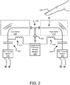
- FIG. 2 illustrates an example circuit diagram 200 for a dual loop antenna with integrated proximity sensing.
- the circuit diagram 200 includes conductive elements (e.g., a low band loop antenna 208 a high band loop antenna 210), a radiofrequency (RF) feed antenna 218, a capacitive proximity sensor module 202, RF tuning switches 204 and 206 and various electrical components.
- the RF feed antenna 218 is electrically excited by an RF feed 220, which may be connected to transceiver or receiver circuitry (not shown).
- the transceiver circuitry electrically excites the RF feed antenna 218 with an electrical signal containing communication data.
- the RF feed antenna 218 is positioned to capacitively couple with the low band loop antenna 208 and the high band loop antenna 210, which are conductive elements that are configured to resonate at a RF communication band when driven by the RF feed antenna 218.
- the RF feed antenna 218 drives the low band loop antenna 208 and the high band loop antenna 210 with a signal containing communication data
- the low band loop antenna 208 and the high band loop antenna 210 transmit a carrier wave at an RF communication band containing the communication data.
- both the low band loop antenna and the high band loop antenna when driven by the RF feed antenna 218 such that the RF feed antenna 219 is capacitively coupled with the low band loop antenna 208 and the high band loop antenna 210, the low band loop antenna 208 and the high band loop antenna 208 may detect and receive communication signals at the RF band (e.g., a low band and a high band) containing communication data.
- the low band loop antenna 208 is configured (e.g., sized, shaped, and tuned) to resonate at an 850 MHz radiofrequency band when driven by the RF feed antenna 218.
- the low band loop antenna 208 detects a communication signal (e.g., a carrier wave) at t ⁇ a frequency of 850 MHz, the low band loop antenna 208 receives the communication signal, which is transmitted to the RF feed antenna 220.
- the RF feed antenna 218 communicates the received communication signal as an electrical signal which is then transmitted to the transceiver (not shown), are conductive elements that are driven to resonate by the RF feed antenna 218.
- the low band loop antenna 208 and the high band loop antenna 210 are configured to resonate (e.g., communicate) at a particular RF communication band.
- the low band loop antenna is configured to resonate at a RF communication band in the range of 700 to 960 MHz
- the high band loop antenna 210 is configured to resonate at a RF communication band in the range of 1900 MHz to 2500 MHz.
- the particular RF communication band of resonation may depend on the RF tuning switches 204 and 206.
- the RF tuning switch 204 may selectively tune the low band loop antenna at a particular RF communication band (e.g., about 850 MHz) within the range of 800 to 960 MHz.
- the RF tuning switch 204 is communicatively (e.g., electrically) connected to a number of communication paths 226 with various electrical components (e.g., inductors) that are used to tune the low band loop antenna 208.
- the RF tuning switch 204 may selectively connect a particular communication path of the number of communication paths 226 to tune the low band loop antenna to communicate at a particular frequency within the low band range (e.g., 700 to 960 MHz).
- the RF tuning switch 206 is communicatively connected to the high band loop antenna 210 and may selectively tune the high band loop antenna 210 to communicate at a particular RF band within the high band range (e.g., 1900 to 2500 MHz).
- the RF tuning switches 204 and 206 may be variable inductors.
- the capacitive proximity sensor module 202 may include software and/or hardware that includes circuitry configured to detect capacitance changes in the conductive elements (e.g., the low band antenna 208 and the high band antenna 210). Such circuitry may be a current meter or other suitable measurement circuit for monitoring signals associated with the capacitor electrode(s) formed by conductive structures (e.g., the low band antenna 208 or the high band antenna 210 and a capacitive external object).
- the capacitive proximity sensor module 202 outputs a low frequency electronic signal to the low band antenna 208 and/or the high band antenna 210. The low frequency electronic signal is communicated between the low band antenna 208 and the capacitive proximity sensor module 202 and/or between the high band antenna 210 and the capacitive proximity sensor module 202.
- the low frequency electronic signal creates an electric field at the conductive elements.
- a capacitive external object e.g., a finger 238 in proximity to the low band antenna 208 and/or the high band antenna 210 interacts with the electric fields causing capacitance changes, which are detectable by the capacitive proximity sensor module 202. As the capacitive external object moves closer to the high band antenna 210 (e.g., a distance x decreases), the capacitance change increases.
- the capacitive proximity sensor module 202 detects the changes in the low frequency signal (e.g., change in amplitude, frequency, or rise/fall time of the low frequency signal waveform) and evaluates the changes in the signal to detect capacitance changes that would indicate proximity of the capacitive external object (e.g., the finger 238).
- a mobile device with the antenna circuitry 200 uses the determined proximity to adjust signal characteristics of the mobile device 100. Such adjustments may consider SAR legal limits and may include adjusting the RF transmission power output by the low band loop antenna 208 and/or the high band loop antenna 210.
- the capacitive external object is the finger 238. However, it should be understood that the capacitive external object may be any object capable of storing electrical charges and causing changes in the low frequency signal.
- the capacitive proximity sensor module 202 is isolated from the RF communication signals communicated between each of the low band antenna 208 and the high band antenna 210 and the respective RF tuning switches (e.g., the RF tuning switch 204 and the RF tuning switch 206) by inductors 214 and 216.
- a RF communication signal e.g., a RF band
- the inductor 216 blocks/filters the RF communication signal (e.g., RF band) communicated between the high band antenna 210 and the RF tuning switch 206.
- the high band antenna 210 e.g., the conductive element
- the inductor 216 and the capacitive proximity sensor module 202 acts as an open circuit for the low frequency signal output by the capacitive proximity sensor module 202.
- the low band antenna 208, the inductor 214 and the capacitive proximity sensor module 202 is an open circuit for the low frequency signal output by the capacitive proximity sensor module 202.
- a device may include more than one capacitive proximity sensor module 202.
- a capacitive proximity sensor module may be included for both the low band antenna 208 and the high band antenna 210.
- the detected capacitance of the low band antenna 208 and the high band antenna 210 may be compared to determine a relative proximity and direction of the capacitive external object such as the finger 238. For example, if the capacitance change detected at the high band antenna 210 is greater than the capacitance change at the low band antenna 208, then it may be determined that the capacitive external object (e.g., the finger 238) is in a direction closer to the high band antenna 210.
- the conductive elements are configured to concurrently communicate in the frequency band of RF signals and communicate the low frequency signal for proximity detection.
- the low frequency band for proximity detection is communicated between the conductive elements 208 and 210 while the conductive element is communicating the band of RF signals (and being RF band switched by the RF tuning switches).
- Concurrent communication/transmission is possible because the distance between the respective frequencies (e.g., the low frequency signal (250 kHz, for example) is distant from the high frequency RF signals (950 MHz, for example).
- the low frequency signal for proximity detection and the high frequency RF signals may be time-division multiplexed (TDM) through the antenna assembly.
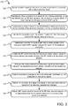
- FIG. 3 illustrates example operations 300 for radiofrequency (RF) transmission and proximity detection using the dual-loop antenna with integrated proximity sensing described herein.
- the operations 300 are for RF communication and proximity detecting using a conductive element (e.g., a loop antenna structure), but it should be understood that the operations 300 are applicable to a dual loop antenna structure (e.g., two conductive elements).
- An exciting operation 302 excites a radiofrequency (RF) feed antenna of an antenna assembly with a direct electrical feed.
- the electrical feed may contain communication data.
- a parasitically driving operation 304 parasitically drives a conductive element of the antenna assembly using the directly excited RF feed antenna.
- the conductive element is driven to communicate in a frequency band of RF signals.
- the conductive element may be configured as a high band loop antenna structure or a low band loop antenna structure. Such configuration may depend on, for example, the size and shape of the conductive element.
- a communicating operation 306 communicates a low frequency signal between a capacitive proximity sensor module of the antenna assembly and the conductive element.
- the capacitive proximity sensor module drives the conductive element with the low frequency signal. It should be understood “between” means that the low frequency signal is communicated by (or on) the conductive element.
- the low frequency signal is communicated between the conductive element and the capacitive proximity sensor module while the conductive element is communicating in the frequency band of RF signals (e.g., the RF signals are traveling being communicated on the conductive element concurrently with the low frequency signals).
- the low frequency signal is output by the capacitive proximity sensor module.
- An isolating operation 308 isolates the capacitive proximity sensor module from the frequency band of RF signals using an inductor.
- the inductor may be communicatively (e.g., electrically) connected between the capacitive proximity sensor circuity and the conductive element.
- the inductor allows the low frequency signals to be communicated between the capacitive proximity sensor module but blocks the RF signals from reaching the capacitive proximity sensor module.
- a selective tuning operation 310 selectively tunes the conductive element to communicate in the frequency band of RF signals using an RF tuning switch of the antenna assembly.
- a variable inductor may be used in place of the RF tuning switch.
- the particular RF band of communication may depend on a current location, carrier, etc.
- the RF tuning switch may be a switch communicatively (e.g., electrically) connected to a plurality of communication paths with various electrical components (e.g., inductors) that are configured for tuning the conductive element to a particular RF communication band.
- the switch may be a radiofrequency microelectromechanical system (RFMEMS) switch.
- a second isolating operation 308 isolates the RF tuning switch from the low frequency signal using a capacitor.
- the capacitor is communicatively/electrically connected between the RF tuning switch and the conductive element. The capacitor blocks the low frequency signal from being communicated to the RF tuning switch.
- An analyzing operation 314 analyzes the low frequency signal communicated between the capacitive proximity sensor module and the conductive element.
- a detecting operation 316 detects capacitive changes in the conductive element based on the analyzed low frequency signal.
- a wave form of the low frequency signal may be analyzed to detect capacitance changes.
- the detecting operation may detect capacitance changes by detecting changes in the waveform (e.g., a change in amplitude, frequency, or rise/fall times of the low frequency signal waveform).
- a determining operation 318 determines proximity of a capacitive object to the conductive element.
- the determining operation 318 can detect type of material of the object (e.g., biological material such as a human finger) based on the detected capacitance changes.
- An adjusting operation 320 adjusts a RF communication power of the RF feed antenna responsive to determining that an object is proximity to the conductive element. Such adjustment may account for SAR legal limits.
- FIG. 4 illustrates an example device 400 for utilizing the dual loop antenna with integrated proximity sensing.
- the device 400 may be a client device such as a laptop, mobile device, desktop, tablet, or a server/cloud device.
- the device 400 includes one or more processor(s) 402, and a memory 404.
- the memory 404 generally includes both volatile memory (e.g., RAM) and non-volatile memory (e.g., flash memory).
- An operating system 410 resides in the memory 404 and is executed by the processor(s) 402.
- the device 400 includes an enclosure 406 that encloses various components of the device 400 (e.g., the processors 402 and the memory 404).
- the enclosure may be partially formed of metal or other suitable material.
- One or more application programs 412 modules or segments such as a capacitive proximity sensor module 480 and a SAR controller 450 are loaded in the memory 404 and/or storage 420 and executed by the processor(s) 402.
- Data such as capacitance measurements, location information, RF band information, SAR thresholds and data, etc. may be loaded into memory 404 or storage 420 and may be retrievable by the processor(s) 402 for use in the by the capacitive proximity sensor module 448, the SAR controller 450, etc.
- the storage 420 may be local to the device 400 or may be remote and communicatively connected to the device 400.
- the storage 420 may store resources that are requestable by client devices (not shown).
- the device 400 includes a power supply 416, which is powered by one or more batteries or other power sources and which provides power to other components of the device 400.
- the power supply 416 may also be connected to an external power source that overrides or recharges the built-in batteries or other power sources.
- the device 400 may include one or more communication transceivers 430 which may be connected to one or more antenna assemblies 432 to provide network connectivity (e.g., mobile phone network, Wi-Fi®, Bluetooth®, etc.) to one or more other servers and/or client devices (e.g., mobile devices, desktop computers, or laptop computers).
- the antenna assemblies 432 may contain one or more RF tuning switch(es) that may be controlled by the capacitive proximity sensor module 448, the SAR controller 450, the network adapter 436, the transceivers 430 etc. to selectively switch RF communication bands in the antenna assemblies 432.
- the capacitive proximity sensor module 448 may be part of the one or more antenna assemblies 432.
- the device 400 may further include a network adapter 436, which is a type of communication device.
- the device 400 may use the adapter and any other types of communication devices for establishing connections over a wide-area network (WAN) or local-area network (LAN). It should be appreciated that the network connections shown are exemplary and that other communications devices and means for establishing a communications link between the device 400 and other devices may be used.
- WAN wide-area network
- LAN local-area network
- the device 400 may include one or more input devices 434 such that a user may enter commands and information (e.g., a keyboard or mouse). These and other input devices may be coupled to the server by one or more interfaces 438 such as a serial port interface, parallel port, universal serial bus (USB), etc.
- the device 400 may further include a display 422 such as a touch screen display.
- the device 400 may include a variety of tangible computer-readable storage media and intangible computer-readable communication signals.
- Tangible computer-readable storage can be embodied by any available media that can be accessed by the device 400 and includes both volatile and nonvolatile storage media, removable and non-removable storage media.
- Tangible computer-readable storage media excludes intangible communications signals and includes volatile and nonvolatile, removable and non-removable storage media implemented in any method or technology for storage of information such as computer readable instructions, data structures, program modules or other data.
- Tangible computer-readable storage media includes, but is not limited to, RAM, ROM, EEPROM, flash memory or other memory technology, CDROM, digital versatile disks (DVD) or other optical disk storage, magnetic cassettes, magnetic tape, magnetic disk storage or other magnetic storage devices, or any other tangible medium which can be used to store the desired information and which can be accessed by the device 400.
- intangible computer-readable communication signals may embody computer readable instructions, data structures, program modules or other data resident in a modulated data signal, such as a carrier wave or other signal transport mechanism.
- modulated data signal means a signal that has one or more of its characteristics set or changed in such a manner as to encode information in the signal.
- intangible communication signals include signals traveling through wired media such as a wired network or direct-wired connection, and wireless media such as acoustic, RF, infrared, and other wireless media.
Landscapes
- Engineering & Computer Science (AREA)
- Computer Networks & Wireless Communication (AREA)
- Support Of Aerials (AREA)
- Near-Field Transmission Systems (AREA)
Claims (12)
- Ensemble antenne (134) configuré pour détecter la proximité d'un objet capacitif (238) capable de stocker des charges électriques et de provoquer des changements dans un signal basse fréquence, l'ensemble antenne comprenant :un premier élément conducteur (104) ayant une première structure d'antenne ;un module de capteur de proximité capacitif (110) électriquement relié au premier élément conducteur, le module de capteur de proximité capacitif (110) étant configuré pour exciter le premier élément conducteur (104) avec le signal basse fréquence pour détecter la proximité de l'objet capacitif (238) par rapport au premier élément conducteur(104) ;une première radiofréquence, RF,un commutateur d'accord (116) relié de façon à communiquer avec le premier élément conducteur (104) et configuré pour accorder sélectivement le premier élément conducteur (104) pour communiquer dans une première bande de fréquences de signaux RF;une antenne d'alimentation RF (102) positionnée de façon à exciter de manière parasite le premier élément conducteur (104) pour communiquer dans la première bande de fréquences de signaux RF ;un second élément conducteur (106) ayant une seconde structure d'antenne,l'antenne d'alimentation RF (102) étant positionnée pour exciter de manière parasite le second élément conducteur (106) pour communiquer dans une seconde bande de fréquences de signaux RF, le module de capteur de proximité capacitif (110) étant électriquement relié au second élément conducteur, et étant configuré pour exciter le second élément conducteur (106) pour détecter la proximité de l'objet capacitif (238) par rapport au second élément conducteur (106), la fréquence du signal basse fréquence étant inférieure aux fréquences de la première bande de fréquences et de la seconde bande de fréquences de signaux RF ;un second commutateur d'accord RF (120) relié de façon à communiquer au second élément conducteur (106) et configuré pour accorder sélectivement le second élément conducteur (106) pour communiquer dans la seconde bande de fréquences des signaux RF ; etun contrôleur de débit d'absorption spécifique (450) configuré pour ajuster une sortie de puissance de transmission RF pour exciter les premier et second éléments conducteurs (104, 106) afin de respecter une limite de débit d'absorption spécifique.
- Ensemble antenne (134) selon la revendication 1, dans lequel le module de capteur de proximité (110) est configuré pour exciter le premier élément conducteur (104) avec le signal basse fréquence pour détecter la proximité de l'objet capacitif (238) simultanément à la transmission de la première bande de fréquences de signaux RF par le premier élément conducteur (104).
- Ensemble antenne (134) selon la revendication 1 ou la revendication 2, l'ensemble antenne (134) comprenant en outre :
un premier inducteur (112) relié de façon à communiquer entre l'élément conducteur (104) et le module de capteur de proximité capacitif (110), le premier inducteur (112) étant configuré pour transmettre le signal basse fréquence entre le premier élément conducteur (104) et le module de capteur de proximité capacitif (110) et pour isoler le module de capteur de proximité capacitif (110) de la première bande de fréquences de signaux RF. - Ensemble antenne (134) selon la revendication 1 ou la revendication 2, l'ensemble antenne (134) comprenant en outre
un premier condensateur relié de façon à communiquer entre le commutateur d'accord RF (116) et le premier élément conducteur (104), le premier condensateur isolant le commutateur d'accord RF (116) du signal basse fréquence avec lequel le module de capteur de proximité capacitif excite le premier élément conducteur (104). - Ensemble antenne (134) selon une quelconque revendication précédente, l'ensemble antenne comprenant en outre :
un second inducteur (114) relié de façon à communiquer entre le second élément conducteur (106) et le module de capteur de proximité capacitif (110), le second inducteur (114) étant configuré pour transmettre le signal basse fréquence entre le second élément conducteur (106) et le module de capteur de proximité capacitif (110) et pour isoler le module de capteur de proximité capacitif (110) de la seconde bande de fréquences de signaux RF. - Ensemble antenne (134) selon une quelconque revendication précédente, l'ensemble antenne comprenant en outre
un second condensateur relié de façon à communiquer entre le commutateur d'accord RF (120) et le second élément conducteur (106), le second condensateur étant configuré pour isoler le commutateur d'accord RF (116) du signal basse fréquence transmis entre le second élément conducteur (106) et le module de capteur de proximité capacitif (110). - Ensemble antenne (134) selon une quelconque revendication précédente, dans lequel le premier élément conducteur (104) forme une partie d'un boîtier (406) d'un dispositif électronique.
- Dispositif électronique (100) incluant un ensemble antenne selon l'une quelconque des revendications 1 à 7.
- Dispositif électronique (100) selon la revendication 8, dans lequel le second élément conducteur (106) est positionné dans un boîtier (406) du dispositif électronique.
- Procédé (300) pour détecter la proximité d'un objet capacitif (238) capable de stocker des charges électriques et de provoquer des changements dans un signal basse fréquence, le procédé comprenant :l'excitation (302) d'une antenne d'alimentation radiofréquence, RF, (102) avec une alimentation directe (220) ;l'excitation parasite (304) d'un premier élément conducteur (104) en utilisant l'antenne d'alimentation RF excitée directement (102), le premier élément conducteur (104) excité pour communiquer dans une première bande de fréquences de signaux RF, le premier élément conducteur ayant une première structure d'antenne,l'excitation parasite d'un second élément conducteur (106) en utilisant l'antenne d'alimentation RF excitée directement (102), le second élément conducteur excité pour communiquer dans une seconde bande de fréquences de signaux RF, le second élément conducteur ayant une seconde structure d'antenne ;la détection (318) de la proximité de l'objet capacitif (238) par rapport au premier élément conducteur (104) avec un module de capteur de proximité capacitif (110) électriquement relié au premier élément conducteur (104) et au second élément conducteur, le module de capteur de proximité capacitif (110) excitant le premier élément conducteur (104) et le second élément conducteur avec un signal basse fréquence pour détecter la proximité de l'objet capacitif (238), la fréquence du signal basse fréquence étant inférieure aux fréquences des première et seconde bandes de fréquences de signaux RF ;l'ajustement d'une sortie de puissance de transmission RF pour exciter les premier et second éléments conducteurs (104, 106) afin de respecter une limite de débit d'absorption spécifique ;l'accord sélectif du premier élément conducteur (104) pour communiquer dans la première bande de fréquences des signaux RF et l'accord sélectif du second élément conducteur (106) pour communiquer dans la seconde bande de fréquences des signaux RF.
- Procédé (300) selon la revendication 10, comprenant en outre :
l'excitation (306) du premier élément conducteur (104) avec le module de capteur capacitif (110) avec le signal basse fréquence pour détecter la proximité de l'objet capacitif (238) simultanément à la transmission de la première bande de fréquences de signaux RF par le premier élément conducteur (104). - Procédé (300) selon la revendication 10, comprenant en outre :
l'isolement (308) du module de capteur de proximité capacitif (110) de la bande de fréquences de signaux RF au moyen d'un premier inducteur (112), le premier inducteur étant relié pour communiquer entre le premier élément conducteur (104) et le module de capteur de proximité capacitif (110).
Applications Claiming Priority (2)
| Application Number | Priority Date | Filing Date | Title |
|---|---|---|---|
| US15/412,997 US10461406B2 (en) | 2017-01-23 | 2017-01-23 | Loop antenna with integrated proximity sensing |
| PCT/US2018/012855 WO2018136256A1 (fr) | 2017-01-23 | 2018-01-09 | Antenne cadre à détection de proximité intégrée |
Publications (2)
| Publication Number | Publication Date |
|---|---|
| EP3571768A1 EP3571768A1 (fr) | 2019-11-27 |
| EP3571768B1 true EP3571768B1 (fr) | 2021-09-08 |
Family
ID=61054561
Family Applications (1)
| Application Number | Title | Priority Date | Filing Date |
|---|---|---|---|
| EP18701878.3A Active EP3571768B1 (fr) | 2017-01-23 | 2018-01-09 | Antenne cadre à détection de proximité intégrée |
Country Status (4)
| Country | Link |
|---|---|
| US (1) | US10461406B2 (fr) |
| EP (1) | EP3571768B1 (fr) |
| CN (1) | CN110199480B (fr) |
| WO (1) | WO2018136256A1 (fr) |
Families Citing this family (41)
| Publication number | Priority date | Publication date | Assignee | Title |
|---|---|---|---|---|
| US10044095B2 (en) | 2014-01-10 | 2018-08-07 | Microsoft Technology Licensing, Llc | Radiating structure with integrated proximity sensing |
| CN105871407B (zh) * | 2016-03-25 | 2019-03-08 | 联想(北京)有限公司 | 一种电子设备 |
| US10879896B2 (en) * | 2016-09-07 | 2020-12-29 | Semtech Corporation | Capacitive proximity sensor in a mobile device and method of limiting radiation absorption |
| TWI642232B (zh) * | 2016-11-11 | 2018-11-21 | 宏碁股份有限公司 | 行動裝置 |
| US10224974B2 (en) | 2017-03-31 | 2019-03-05 | Microsoft Technology Licensing, Llc | Proximity-independent SAR mitigation |
| KR102408872B1 (ko) * | 2018-01-05 | 2022-06-15 | 삼성전자주식회사 | 공진 주파수를 조정하는 회로 및 이를 포함하는 전자 장치 |
| US10505394B2 (en) * | 2018-04-21 | 2019-12-10 | Tectus Corporation | Power generation necklaces that mitigate energy absorption in the human body |
| US10895762B2 (en) | 2018-04-30 | 2021-01-19 | Tectus Corporation | Multi-coil field generation in an electronic contact lens system |
| US10838239B2 (en) | 2018-04-30 | 2020-11-17 | Tectus Corporation | Multi-coil field generation in an electronic contact lens system |
| US10790700B2 (en) | 2018-05-18 | 2020-09-29 | Tectus Corporation | Power generation necklaces with field shaping systems |
| US11693519B2 (en) * | 2018-07-10 | 2023-07-04 | Sensortek Technology Corp. | Proximity sensor and proximity sensing method |
| US11137622B2 (en) | 2018-07-15 | 2021-10-05 | Tectus Corporation | Eye-mounted displays including embedded conductive coils |
| CN108987908B (zh) * | 2018-07-27 | 2021-05-18 | 北京小米移动软件有限公司 | 一种天线及移动终端 |
| CN110971313A (zh) * | 2018-09-12 | 2020-04-07 | 中兴通讯股份有限公司 | 一种车载tbox及其天线实时切换方法、设备及可读存储介质 |
| US10986510B2 (en) * | 2018-09-25 | 2021-04-20 | Apple Inc. | Electronic devices having sensor-augmented wireless link management |
| US10925007B2 (en) * | 2018-11-02 | 2021-02-16 | Apple Inc. | Dynamic power reduction requests for wireless communications |
| US10838232B2 (en) | 2018-11-26 | 2020-11-17 | Tectus Corporation | Eye-mounted displays including embedded solenoids |
| US11101834B2 (en) * | 2018-11-30 | 2021-08-24 | Qualcomm Incorporated | Apparatus and method for detecting lateral electromagnetic exposure and device grip for controlling signal transmission |
| US10644543B1 (en) | 2018-12-20 | 2020-05-05 | Tectus Corporation | Eye-mounted display system including a head wearable object |
| KR102687399B1 (ko) | 2019-06-10 | 2024-07-23 | 삼성전자 주식회사 | 안테나와 연결된 주파수 분기 회로 및 그것을 포함하는 전자 장치 |
| CN112114202B (zh) * | 2019-07-12 | 2021-07-23 | 中兴通讯股份有限公司 | 一种检测sar的装置、降低sar的方法及移动终端 |
| US10944290B2 (en) | 2019-08-02 | 2021-03-09 | Tectus Corporation | Headgear providing inductive coupling to a contact lens |
| US11762624B2 (en) * | 2019-09-23 | 2023-09-19 | Sonos, Inc. | Capacitive touch sensor with integrated antenna(s) for playback devices |
| CN111366791A (zh) * | 2020-03-03 | 2020-07-03 | 上海闻泰信息技术有限公司 | 电磁波吸收比值的检测方法、装置及电子设备 |
| TWI850547B (zh) * | 2020-03-31 | 2024-08-01 | 昇佳電子股份有限公司 | 天線與近接感測電路之傳輸架構 |
| US11611374B2 (en) | 2020-08-05 | 2023-03-21 | Apple Inc. | Low-frequency detection and ranging |
| KR102902132B1 (ko) * | 2020-09-04 | 2025-12-19 | 삼성전자 주식회사 | 커패시턴스 센서를 포함하는 전자 장치 |
| CN114337715B (zh) * | 2020-09-30 | 2024-10-01 | 南京矽力微电子(香港)有限公司 | 多段式共辐射体天线及应用该天线的穿戴式装置 |
| US12476357B2 (en) * | 2020-12-21 | 2025-11-18 | Intel Corporation | Antenna assembly with isolation network |
| CN112821031B (zh) | 2020-12-29 | 2024-01-02 | Oppo广东移动通信有限公司 | 电子设备 |
| CN115342720A (zh) * | 2021-05-14 | 2022-11-15 | Oppo广东移动通信有限公司 | 电子设备 |
| CN113489554B (zh) * | 2021-07-05 | 2023-07-14 | 东集技术股份有限公司 | 一种通信设备及降低通信设备的sar的方法 |
| CN113571895B (zh) * | 2021-07-23 | 2023-11-28 | Oppo广东移动通信有限公司 | 天线装置的接地结构、天线装置及电子设备 |
| CN115704919B (zh) * | 2021-08-03 | 2026-03-10 | 南京矽力微电子(香港)有限公司 | 移动装置 |
| CN115708256A (zh) * | 2021-08-20 | 2023-02-21 | 荣耀终端有限公司 | 一种耦合馈电的终端单极子天线 |
| US12512583B2 (en) | 2021-09-23 | 2025-12-30 | Semtech Corporation | Proximity sensor for RF control |
| WO2023082169A1 (fr) * | 2021-11-12 | 2023-05-19 | Goertek Inc. | Ensemble à éléments multiples, dispositif électronique doté dudit ensemble et procédé de commande associé |
| CN115014401A (zh) * | 2022-05-13 | 2022-09-06 | 深圳市锐尔觅移动通信有限公司 | 检测电路、方法、装置、移动终端及计算机可读存储介质 |
| WO2023239123A1 (fr) * | 2022-06-07 | 2023-12-14 | 삼성전자 주식회사 | Dispositif électronique et procédé associé de sélection d'antenne d'émission |
| CN118539137A (zh) * | 2023-02-22 | 2024-08-23 | 北京小米移动软件有限公司 | 天线结构及终端设备 |
| CN116908925A (zh) * | 2023-06-30 | 2023-10-20 | 联想(北京)有限公司 | 一种电子设备及确定方法 |
Family Cites Families (251)
| Publication number | Priority date | Publication date | Assignee | Title |
|---|---|---|---|---|
| DE2460057B2 (de) | 1974-12-19 | 1977-02-10 | Robert Bosch Gmbh, 7000 Stuttgart | Schaltanordnung mit einem streufeldkondensator |
| US4729129A (en) | 1986-10-15 | 1988-03-01 | Itt Avionics A Division Of Itt Corporation | VSWR protection circuit apparatus |
| US4806944A (en) | 1987-09-14 | 1989-02-21 | General Electric Company | Switchable matching network for an element of a steerable antenna array |
| US5212621A (en) | 1990-04-26 | 1993-05-18 | Cnc Retrofits, Inc. | Proximity switched machine control method and apparatus |
| EP0479168B1 (fr) | 1990-10-01 | 1997-02-26 | Murata Manufacturing Co., Ltd. | Appareil de supervision d'antenne avec unité de mesure du taux d'ondes stationnaires |
| US5166679A (en) | 1991-06-06 | 1992-11-24 | The United States Of America As Represented By The Administrator Of The National Aeronautics & Space Administration | Driven shielding capacitive proximity sensor |
| US5363051A (en) | 1992-11-23 | 1994-11-08 | The United States Of America As Represented By The Administrator Of The National Aeronautics And Space Administration | Steering capaciflector sensor |
| JPH0766287A (ja) | 1993-08-23 | 1995-03-10 | Matsushita Electric Ind Co Ltd | 半導体装置及びその製造方法 |
| US5564086A (en) | 1993-11-29 | 1996-10-08 | Motorola, Inc. | Method and apparatus for enhancing an operating characteristic of a radio transmitter |
| US5649306A (en) | 1994-09-16 | 1997-07-15 | Motorola, Inc. | Portable radio housing incorporating diversity antenna structure |
| TW347616B (en) | 1995-03-31 | 1998-12-11 | Qualcomm Inc | Method and apparatus for performing fast power control in a mobile communication system a method and apparatus for controlling transmission power in a mobile communication system is disclosed. |
| KR100202501B1 (ko) | 1996-12-30 | 1999-06-15 | 서평원 | 이동통신시스템 기지국의 송신전력/송수신정재파비 측정회로 |
| GB9823396D0 (en) | 1998-10-27 | 1998-12-23 | Roke Manor Research | Method of and apparatus for power control |
| US6725061B1 (en) | 1999-01-12 | 2004-04-20 | Qualcomm, Incorporated | System and method for the automatic identification of accessories coupled to a wireless communication device |
| US6411108B1 (en) | 1999-11-05 | 2002-06-25 | Sensor Technologies, Inc. | Noncontact signal analyzer |
| WO2001048858A2 (fr) | 1999-12-14 | 2001-07-05 | Rangestar Wireless, Inc. | Ensemble antenne a large bande a faible taux d'absorption specifique (das) |
| US20020009976A1 (en) | 2000-01-07 | 2002-01-24 | Rashidi Taymor S. | Radiation protection device for cellular telephones |
| JP2002043957A (ja) | 2000-07-19 | 2002-02-08 | Hitachi Kokusai Electric Inc | 高周波信号送信装置 |
| US8744384B2 (en) | 2000-07-20 | 2014-06-03 | Blackberry Limited | Tunable microwave devices with auto-adjusting matching circuit |
| DE10040228A1 (de) | 2000-08-17 | 2002-02-28 | Siemens Ag | Verfahren zur Regelung der Sendeleistung in einem Funksystem |
| US7124193B1 (en) | 2000-08-24 | 2006-10-17 | At&T Corp. | Method of using link adaptation and power control for streaming services in wireless networks |
| WO2002063582A2 (fr) | 2001-02-07 | 2002-08-15 | Gerenraich Family Trust | Systeme de commande equipe d'un detecteur capacitif |
| US6937195B2 (en) | 2001-04-11 | 2005-08-30 | Kyocera Wireless Corp. | Inverted-F ferroelectric antenna |
| US6804474B2 (en) | 2001-07-24 | 2004-10-12 | Canon Kabushiki Kaisha | Image forming apparatus |
| JP2003110329A (ja) | 2001-07-25 | 2003-04-11 | Matsushita Electric Ind Co Ltd | 内蔵アンテナ装置 |
| JP3633526B2 (ja) | 2001-08-09 | 2005-03-30 | 株式会社デンソー | 非共振ノックセンサの製造方法及び装置 |
| US6989745B1 (en) | 2001-09-06 | 2006-01-24 | Vistascape Security Systems Corp. | Sensor device for use in surveillance system |
| US7146139B2 (en) | 2001-09-28 | 2006-12-05 | Siemens Communications, Inc. | System and method for reducing SAR values |
| US7053629B2 (en) | 2001-09-28 | 2006-05-30 | Siemens Communications, Inc. | System and method for detecting the proximity of a body |
| US7039435B2 (en) | 2001-09-28 | 2006-05-02 | Agere Systems Inc. | Proximity regulation system for use with a portable cell phone and a method of operation thereof |
| US7071776B2 (en) | 2001-10-22 | 2006-07-04 | Kyocera Wireless Corp. | Systems and methods for controlling output power in a communication device |
| US6833756B2 (en) | 2002-01-24 | 2004-12-21 | Broadcom Corporation | Input buffer amplifier with centroidal layout |
| US6842018B2 (en) | 2002-05-08 | 2005-01-11 | Mcintosh Robert B. | Planar capacitive transducer |
| US6657595B1 (en) | 2002-05-09 | 2003-12-02 | Motorola, Inc. | Sensor-driven adaptive counterpoise antenna system |
| US20030228846A1 (en) | 2002-06-05 | 2003-12-11 | Shlomo Berliner | Method and system for radio-frequency proximity detection using received signal strength variance |
| AU2003243857A1 (en) | 2002-06-21 | 2004-01-06 | Research In Motion Limited | Multiple-element antenna with parasitic coupler |
| EP1529322A1 (fr) | 2002-08-05 | 2005-05-11 | Koninklijke Philips Electronics N.V. | Systeme d'antenne a diversite et procede pour faire fonctionner ledit systeme |
| JP2004201278A (ja) | 2002-12-06 | 2004-07-15 | Sharp Corp | パターンアンテナ |
| US7167093B2 (en) | 2002-12-10 | 2007-01-23 | Invisa, Inc. | Method of steering capacitor fields for use in capacitive sensing security systems |
| US6791500B2 (en) | 2002-12-12 | 2004-09-14 | Research In Motion Limited | Antenna with near-field radiation control |
| US6803883B2 (en) | 2003-02-13 | 2004-10-12 | Spectrasite Communications, Inc. | Radio frequency electromagnetic emissions shield |
| US7072620B2 (en) | 2003-04-03 | 2006-07-04 | Kyocera Wireless Corp. | System and method for regulating antenna electrical length |
| US6985113B2 (en) | 2003-04-18 | 2006-01-10 | Matsushita Electric Industrial Co., Ltd. | Radio antenna apparatus provided with controller for controlling SAR and radio communication apparatus using the same radio antenna apparatus |
| CA2435900C (fr) | 2003-07-24 | 2008-10-21 | Research In Motion Limited | Coussinet conducteur flottant permettant la stabilisation du rendement d'antenne et la reduction du bruit |
| PT103006A (pt) | 2003-08-07 | 2005-02-28 | Juvenal | Processo para a eliminacao/reducao de compostos com gosto/odor a mofo em materiais para contacto com alimentos e bebidas, e em alimentos e bebidas |
| US7162264B2 (en) | 2003-08-07 | 2007-01-09 | Sony Ericsson Mobile Communications Ab | Tunable parasitic resonators |
| FR2859064B1 (fr) | 2003-08-18 | 2005-12-30 | Satimo Sa | Dispositif de controle du debit d'absorption specifique d'objets rayonnants fabriques en serie et notamment de telephones portables |
| US20080218493A1 (en) | 2003-09-03 | 2008-09-11 | Vantage Controls, Inc. | Display With Motion Sensor |
| US20050073507A1 (en) | 2003-10-06 | 2005-04-07 | Richter Paul J. | Touch input sensing device |
| GB0328811D0 (en) | 2003-12-12 | 2004-01-14 | Antenova Ltd | Antenna for mobile telephone handsets.PDAs and the like |
| KR100612142B1 (ko) | 2004-01-16 | 2006-08-11 | 주식회사 케이티프리텔 | 이동통신 단말을 이용한 공중선계 원격 측정 감시 장치 및그 방법 |
| US7109923B2 (en) | 2004-02-23 | 2006-09-19 | Nokia Corporation | Diversity antenna arrangement |
| US7580837B2 (en) | 2004-08-12 | 2009-08-25 | At&T Intellectual Property I, L.P. | System and method for targeted tuning module of a speech recognition system |
| JPWO2006082860A1 (ja) | 2005-02-01 | 2008-06-26 | 松下電器産業株式会社 | 携帯無線機 |
| US20060244663A1 (en) | 2005-04-29 | 2006-11-02 | Vulcan Portals, Inc. | Compact, multi-element antenna and method |
| EP1732167A1 (fr) | 2005-05-31 | 2006-12-13 | Research In Motion Limited | Dispositif de communication mobile sans fil comprenant une antenne GPS et des directeurs de rayonnement conductives |
| JP4566825B2 (ja) | 2005-06-03 | 2010-10-20 | レノボ・シンガポール・プライベート・リミテッド | 携帯端末装置のアンテナの制御方法及び当該携帯端末装置 |
| US7151382B1 (en) | 2005-09-22 | 2006-12-19 | Rockwell Collins, Inc. | Apparatus and method for radio frequency power and standing wave ratio measurement |
| WO2007043150A1 (fr) | 2005-10-06 | 2007-04-19 | Matsushita Electric Industrial Co., Ltd. | Dispositif d'antenne pour terminal portable et terminal portable |
| US20070111681A1 (en) | 2005-11-14 | 2007-05-17 | Alberth William P Jr | Transmit power allocation in wireless communication devices |
| US7656353B2 (en) | 2005-11-29 | 2010-02-02 | Research In Motion Limited | Mobile wireless communications device comprising a satellite positioning system antenna with active and passive elements and related methods |
| US7729715B2 (en) | 2005-12-30 | 2010-06-01 | Motorola, Inc. | Method and apparatus for power reduction for E-TFC selection |
| JP4632176B2 (ja) | 2006-01-20 | 2011-02-16 | 株式会社村田製作所 | アンテナ及び無線通信機 |
| JP2007267181A (ja) | 2006-03-29 | 2007-10-11 | Matsushita Electric Ind Co Ltd | 高周波電力送信装置 |
| US8559999B2 (en) | 2006-05-29 | 2013-10-15 | Telefonaktiebolaget Lm Ericsson (Publ) | Channel quality prediction in HSDPA systems |
| JP5295106B2 (ja) | 2006-06-30 | 2013-09-18 | コーニンクレッカ フィリップス エレクトロニクス エヌ ヴィ | スポットライト制御デバイスの近接検出およびスポットライト制御デバイスにより、照明システムを制御するためのデバイスおよび方法 |
| US20080051165A1 (en) | 2006-08-28 | 2008-02-28 | Motorola, Inc. | Rf power control using proximity sensor |
| KR100814432B1 (ko) | 2006-08-29 | 2008-03-18 | 삼성전자주식회사 | Sar이 감소된 이중대역 역 f안테나 |
| US8442572B2 (en) | 2006-09-08 | 2013-05-14 | Qualcomm Incorporated | Method and apparatus for adjustments for delta-based power control in wireless communication systems |
| KR100828872B1 (ko) | 2006-10-23 | 2008-05-09 | 엘지이노텍 주식회사 | Rf 센서 시스템 |
| EP2084825B1 (fr) | 2006-11-20 | 2018-05-09 | Telefonaktiebolaget LM Ericsson (publ) | Procédé pour contrer une interférence de transmissions haut débit |
| KR100782512B1 (ko) | 2006-12-28 | 2007-12-05 | 삼성전자주식회사 | 전자파 흡수율을 개선한 휴대 단말기 |
| US7554496B2 (en) | 2007-04-10 | 2009-06-30 | Research In Motion Limited | Mobile wireless communications device including a ground patch providing specific absorption rate (SAR) reduction and related methods |
| ATE459192T1 (de) | 2007-06-21 | 2010-03-15 | Research In Motion Ltd | Mobile drahtlose kommunikationsvorrichtung mit elektrisch leitenden und elektrisch schwebenden strahlformungselementen und entsprechende verfahren |
| US8063375B2 (en) | 2007-06-22 | 2011-11-22 | Intel-Ge Care Innovations Llc | Sensible motion detector |
| US20090047998A1 (en) | 2007-08-16 | 2009-02-19 | Motorola, Inc. | Method and apparatus for controlling power transmission levels for a mobile station having transmit diversity |
| US8068054B2 (en) | 2008-02-02 | 2011-11-29 | Zanio, Inc. | Receiver with means for ensuring bona fide of received signals |
| JP2009253479A (ja) | 2008-04-02 | 2009-10-29 | Sony Ericsson Mobilecommunications Japan Inc | 携帯通信端末及びその送信特性制御方法 |
| US8159399B2 (en) | 2008-06-03 | 2012-04-17 | Apple Inc. | Antenna diversity systems for portable electronic devices |
| US8417296B2 (en) | 2008-06-05 | 2013-04-09 | Apple Inc. | Electronic device with proximity-based radio power control |
| US8941394B2 (en) | 2008-06-25 | 2015-01-27 | Silicon Laboratories Inc. | Capacitive sensor system with noise reduction |
| US20090325710A1 (en) | 2008-06-27 | 2009-12-31 | Microsoft Corporation | Dynamic Selection Of Sensitivity Of Tilt Functionality |
| US8726497B2 (en) | 2008-08-01 | 2014-05-20 | 3M Innovative Properties Company | Methods of making composite electrodes |
| EP2311291B1 (fr) | 2008-08-08 | 2014-07-30 | Telefonaktiebolaget L M Ericsson (publ) | Procédé de sélection d'une combinaison de format de transport améliorée sur la base d'une consommation d'énergie déterminée |
| TWI478437B (zh) | 2008-08-29 | 2015-03-21 | Chi Mei Comm Systems Inc | 天線模組及使用該天線模組之可攜式電子裝置 |
| US8238961B2 (en) | 2008-09-03 | 2012-08-07 | Google Inc. | Low radiation wireless communicator |
| JP2010098683A (ja) | 2008-10-20 | 2010-04-30 | Panasonic Corp | アンテナ装置 |
| US8214003B2 (en) | 2009-03-13 | 2012-07-03 | Pong Research Corporation | RF radiation redirection away from portable communication device user |
| CN201663225U (zh) | 2008-11-06 | 2010-12-01 | 黄耀辉 | 嵌入电池内的天线、无线设备和无线设备的智能外壳 |
| US8957813B2 (en) | 2009-03-13 | 2015-02-17 | Pong Research Corporation | External case for redistribution of RF radiation away from wireless communication device user and wireless communication device incorporating RF radiation redistribution elements |
| JP5401132B2 (ja) | 2009-01-20 | 2014-01-29 | 信越ポリマー株式会社 | 電波透過性装飾部材およびその製造方法 |
| US8723531B2 (en) | 2009-03-12 | 2014-05-13 | Sige Semiconductor, Inc. | Integrated VSWR detector for monolithic microwave integrated circuits |
| US8217843B2 (en) | 2009-03-13 | 2012-07-10 | Ruckus Wireless, Inc. | Adjustment of radiation patterns utilizing a position sensor |
| US8744539B2 (en) | 2009-05-01 | 2014-06-03 | Netgear, Inc. | Method and apparatus for controlling radiation characteristics of transmitter of wireless device in correspondence with transmitter orientation |
| US8421685B2 (en) | 2009-05-07 | 2013-04-16 | Ethertronics, Inc. | Spatial filter for near field modification in a wireless communication device |
| DE102009020218B8 (de) | 2009-05-07 | 2011-05-12 | Fraunhofer-Gesellschaft zur Förderung der angewandten Forschung e.V. | Detektor und Verfahren zum Detektieren elektromagnetischer Strahlung und Computerprogramm zur Durchführung des Verfahrens |
| US8213982B2 (en) | 2009-06-01 | 2012-07-03 | Hewlett-Packard Development Company, L.P. | Enhanced internal antenna architecture for a mobile computing device |
| US20100317302A1 (en) | 2009-06-12 | 2010-12-16 | Novatel Wireless | System and method for controlling rf explosure levels |
| US20100321325A1 (en) | 2009-06-17 | 2010-12-23 | Springer Gregory A | Touch and display panel antennas |
| CN101938039B (zh) | 2009-07-01 | 2015-03-11 | 深圳富泰宏精密工业有限公司 | 天线结构及应用该天线结构的无线通信装置 |
| US8466839B2 (en) | 2009-07-17 | 2013-06-18 | Apple Inc. | Electronic devices with parasitic antenna resonating elements that reduce near field radiation |
| US8432322B2 (en) * | 2009-07-17 | 2013-04-30 | Apple Inc. | Electronic devices with capacitive proximity sensors for proximity-based radio-frequency power control |
| AU2014202603B2 (en) | 2009-07-17 | 2015-07-09 | Apple Inc. | Electronic devices with capacitive proximity sensors for proximity-based radio-frequency power control |
| US8855830B2 (en) | 2009-08-21 | 2014-10-07 | Allure Energy, Inc. | Energy management system and method |
| US9136594B2 (en) | 2009-08-20 | 2015-09-15 | Qualcomm Incorporated | Compact multi-band planar inverted F antenna |
| US8442457B2 (en) | 2009-09-08 | 2013-05-14 | Google Inc. | System and method for adaptive beamforming for specific absorption rate control |
| US8269511B2 (en) | 2009-09-08 | 2012-09-18 | Synaptics Incorporated | Sensing and defining an input object |
| FI20096101A0 (fi) | 2009-10-27 | 2009-10-27 | Pulse Finland Oy | Menetelmä ja järjestely antennin sovittamiseksi |
| WO2011058128A1 (fr) | 2009-11-12 | 2011-05-19 | Irex Technologies B.V. | Dispositif client en conformité avec les limitations sar |
| US8483632B2 (en) | 2009-11-13 | 2013-07-09 | Motorola Mobility Llc | Radiated power control systems and methods in wireless communication devices |
| US8737934B2 (en) | 2009-11-24 | 2014-05-27 | Symbol Technologies, Inc. | Setting SAR exposure limit of mobile devices |
| US8520586B1 (en) | 2009-12-16 | 2013-08-27 | Qualcomm Incorporated | Discovery and connection coexistence mechanism for wireless devices |
| US8792930B1 (en) | 2010-01-22 | 2014-07-29 | Amazon Technologies, Inc. | Power management for wireless transmissions |
| TWI381303B (zh) | 2010-02-09 | 2013-01-01 | Oji Paper Co | 導電性積層體及使用其之觸控面板 |
| US8358615B2 (en) | 2010-03-11 | 2013-01-22 | Research In Motion Limited | Modulation and coding scheme selection method for a specific absorption rate compliant communication device |
| US9331694B2 (en) | 2010-03-25 | 2016-05-03 | Silego Technology, Inc. | Capacitive coupling based proximity sensor |
| US8781420B2 (en) | 2010-04-13 | 2014-07-15 | Apple Inc. | Adjustable wireless circuitry with antenna-based proximity detector |
| DE102011015806A1 (de) | 2011-04-01 | 2012-10-04 | Ident Technology Ag | Displayeinrichtung |
| WO2011133657A2 (fr) | 2010-04-20 | 2011-10-27 | Paratek Microwave, Inc. | Procédé et appareil permettant de gérer l'interférence dans un dispositif de communication |
| EP2381527B1 (fr) | 2010-04-22 | 2018-10-31 | BlackBerry Limited | Ensemble d'antenne avec agencement de plan de base étendu électriquement et procédé associé |
| EP2395602A1 (fr) | 2010-06-08 | 2011-12-14 | Research In Motion Limited | Système de diversité d'antenne double basse fréquence |
| US9070969B2 (en) | 2010-07-06 | 2015-06-30 | Apple Inc. | Tunable antenna systems |
| US8538351B2 (en) | 2010-07-20 | 2013-09-17 | Blackberry Limited | Radiation power level control system and method for a wireless communication device based on a tracked radiation history |
| EP2410661B1 (fr) | 2010-07-20 | 2014-10-29 | BlackBerry Limited | Système de contrôle de la puissance de radiation et procédé pour dispositif de communication sans fil basé sur une histoire de radiation suivie |
| US20120021707A1 (en) | 2010-07-26 | 2012-01-26 | Qualcomm Incorporated | Apparatus and method for adjustment of transmitter power in a system |
| GB201012865D0 (en) | 2010-07-30 | 2010-09-15 | Freewave Ltd | Personal communications device |
| CN201805000U (zh) | 2010-08-16 | 2011-04-20 | 佳邦科技股份有限公司 | 整合于金属壳体的天线结构 |
| KR101114873B1 (ko) | 2010-08-31 | 2012-02-28 | 주식회사 이음플러스 | 근접센서를 이용한 이동 감지장치 및 이동 감지방법 |
| EP2471191A1 (fr) | 2010-09-21 | 2012-07-04 | Broadcom Corporation | Gestion de la puissance d'émission pour débits d'absorption spécifiques |
| KR101722237B1 (ko) | 2010-09-28 | 2017-03-31 | 삼성전자주식회사 | 휴대단말기의 통신 전력 제어장치 및 방법 |
| US20120074961A1 (en) | 2010-09-29 | 2012-03-29 | Kopin Corporation | Capacitive sensor with active shield electrode |
| US8565205B2 (en) | 2010-11-04 | 2013-10-22 | Qualcomm Incorporated | Specific absorption rate backoff in power headroom report |
| WO2012067563A1 (fr) | 2010-11-16 | 2012-05-24 | Telefonaktiebolaget L M Ericsson (Publ) | Commande dynamique du débit d'absorption spécifique, afin de rendre minimale l'exposition aux rf |
| US8760349B2 (en) | 2010-11-26 | 2014-06-24 | Intel Corporation | Method and apparatus for in-mold laminate antennas |
| TW201228104A (en) | 2010-12-16 | 2012-07-01 | Quanta Comp Inc | Method to reduce specific absorption rate of electronic device and electronic device with low specific absorption rate |
| TWI489358B (zh) | 2010-12-28 | 2015-06-21 | Chi Mei Comm Systems Inc | 具有接近感測器模組之無線通訊裝置 |
| CN102064812B (zh) | 2010-12-30 | 2012-10-03 | 广东盈科电子有限公司 | 一种近距离辨别人或物感应装置 |
| WO2012091651A1 (fr) | 2010-12-30 | 2012-07-05 | Telefonaktiebolaget L M Ericsson (Publ) | Procédés et appareils permettant l'indication d'un recul de puissance dans un rapport de marge de puissance au sein d'un système de télécommunications |
| EP3214875B1 (fr) | 2011-01-07 | 2020-10-07 | InterDigital Patent Holdings, Inc. | Procédés, appareils et systèmes de gestion de recul de puissance additionnel |
| US8644778B2 (en) | 2011-01-21 | 2014-02-04 | Nokia Corporation | Usage of measurement antenna transmitting communication signal for power adjustment in wireless device |
| US8577289B2 (en) | 2011-02-17 | 2013-11-05 | Apple Inc. | Antenna with integrated proximity sensor for proximity-based radio-frequency power control |
| US9026059B2 (en) | 2011-02-17 | 2015-05-05 | Futurewei Technologies, Inc. | Adaptive maximum power limiting using capacitive sensing in a wireless device |
| DE102011004622B4 (de) | 2011-02-23 | 2013-04-18 | Ident Technology Ag | Kapazitive Sensoreinrichtung und Funkgerät mit kapazitiver Sensoreinrichtung sowie Verfahren zum Einstellen einer Sendeleistung eines Funkgerätes |
| US8952860B2 (en) | 2011-03-01 | 2015-02-10 | Apple Inc. | Antenna structures with carriers and shields |
| US8909282B2 (en) | 2011-03-04 | 2014-12-09 | Qualcomm Incorporated | Systems and methods for dynamic transmission power limit back-off for specific absorption rate compliance |
| US8781437B2 (en) | 2011-03-04 | 2014-07-15 | Qualcomm Incorporated | Systems and methods for dynamic transmission power limit back-off for specific absorption rate compliance |
| JP5368503B2 (ja) | 2011-03-31 | 2013-12-18 | 株式会社エヌ・ティ・ティ・ドコモ | 移動局及び無線通信システムに使用される方法 |
| EP2509229B1 (fr) | 2011-04-05 | 2015-02-25 | BlackBerry Limited | Dispositif de communications sans fil mobiles avec un contrôle de la puissance transmise basée sur la proximité et procédés correspondants |
| US8326385B2 (en) | 2011-04-05 | 2012-12-04 | Research In Motion Limited | Mobile wireless communications device with proximity based transmitted power control and related methods |
| WO2012143936A1 (fr) | 2011-04-21 | 2012-10-26 | Muthukumar Prasad | Système d'optimisation de diagramme de rayonnement d'antenne actif intelligent pour dispositifs mobiles réalisé par détection de l'environnement de proximité du dispositif quant à la propriété, la position, l'orientation, la qualité du signal et les modes de fonctionnement |
| JP5664443B2 (ja) | 2011-04-28 | 2015-02-04 | 富士通株式会社 | 情報処理装置、電波強度制御方法およびプログラム |
| WO2012158693A1 (fr) * | 2011-05-16 | 2012-11-22 | Paratek Microwave, Inc. | Procédé et appareil d'accord d'un dispositif de communication |
| US8594584B2 (en) | 2011-05-16 | 2013-11-26 | Blackberry Limited | Method and apparatus for tuning a communication device |
| US8975903B2 (en) | 2011-06-09 | 2015-03-10 | Ford Global Technologies, Llc | Proximity switch having learned sensitivity and method therefor |
| US9037190B2 (en) | 2011-06-14 | 2015-05-19 | Ethertronics, Inc. | Adaptive repeater for improved communication system performance |
| US8775103B1 (en) | 2011-06-17 | 2014-07-08 | Amazon Technologies, Inc. | Proximity sensor calibration and configuration |
| US9578159B2 (en) | 2011-06-20 | 2017-02-21 | Prasad Muthukumar | Fisheye lens based proactive user interface for mobile devices |
| EP2724480B1 (fr) | 2011-06-21 | 2015-08-19 | Telefonaktiebolaget L M Ericsson (publ) | Sélection de l'émission montante à antennes multiples pour améliorer la couverture |
| US20120329524A1 (en) * | 2011-06-22 | 2012-12-27 | Kent Joel C | Touch sensor and antenna integration along an electronic device housing |
| UA74126U (ru) | 2011-06-24 | 2012-10-25 | Владимир Александрович Елин | Мобильное радиоустройство с дозиметром-радиометром |
| KR20130008947A (ko) | 2011-07-13 | 2013-01-23 | 삼성전자주식회사 | 휴대단말기의 송신출력 제한장치 및 방법 |
| EP2735198B1 (fr) | 2011-07-18 | 2018-06-06 | Nokia Technologies Oy | Commande intelligente de la puissance de fréquences radio |
| FR2978595A1 (fr) | 2011-07-28 | 2013-02-01 | St Microelectronics Crolles 2 | Transformateur du type symetrique-dissymetrique |
| TWI448697B (zh) | 2011-08-02 | 2014-08-11 | Jieng Tai Internat Electric Corp | 天線裝置與訊號處理裝置 |
| US8626101B2 (en) | 2011-08-18 | 2014-01-07 | Apple Inc. | Wireless electronic device with antenna cycling |
| US9287627B2 (en) * | 2011-08-31 | 2016-03-15 | Apple Inc. | Customizable antenna feed structure |
| DE102011053314A1 (de) | 2011-09-06 | 2013-03-07 | Huf Hülsbeck & Fürst Gmbh & Co. Kg | Kapazitive Sensoranordnung |
| US9086299B2 (en) | 2011-09-07 | 2015-07-21 | Futurewei Technologies, Inc. | Wireless dongle angular position sensor |
| CN202276339U (zh) | 2011-10-18 | 2012-06-13 | 中兴通讯股份有限公司 | 无线终端 |
| WO2013057630A1 (fr) | 2011-10-21 | 2013-04-25 | University Of Manitoba | Capteur passif sans fil |
| US8995938B2 (en) | 2011-11-14 | 2015-03-31 | Blackberry Limited | Radiation power level control system and method for a wireless communication device having tunable elements |
| US9337833B2 (en) | 2011-11-14 | 2016-05-10 | Atmel Corporation | Driven shield for shaping an electric field of a touch sensor |
| US8723749B2 (en) | 2011-11-17 | 2014-05-13 | Wistron Neweb Corporation | Radio-frequency device and wireless communication device |
| JP5148740B1 (ja) | 2011-11-30 | 2013-02-20 | 株式会社東芝 | 携帯型情報端末 |
| US9144041B2 (en) | 2011-12-14 | 2015-09-22 | Microchip Technology Incorporated | Capacitive/inductive proximity detection for Wi-Fi protection |
| US8515496B2 (en) | 2011-12-15 | 2013-08-20 | Amazon Technologies, Inc. | Antenna deployment switching for data communication of a user device |
| EP2798746B1 (fr) | 2011-12-29 | 2018-05-16 | Intel Corporation | Dispositif sans fil et méthode de sélection d'antenne |
| US8831528B2 (en) | 2012-01-04 | 2014-09-09 | Futurewei Technologies, Inc. | SAR control using capacitive sensor and transmission duty cycle control in a wireless device |
| US8989665B2 (en) | 2012-01-05 | 2015-03-24 | Blackberry Limited | Portable electronic device for reducing specific absorption rate |
| US9743565B2 (en) | 2012-01-08 | 2017-08-22 | Access Business Group International Llc | Wireless power transfer through conductive materials |
| US20130178167A1 (en) | 2012-01-09 | 2013-07-11 | Novatel Wireless, Inc. | System and method for reducing specific absorption rate of a wireless communications device |
| CN102590867B (zh) | 2012-02-03 | 2015-05-27 | 华为终端有限公司 | 移动终端 |
| CN103248747B (zh) | 2012-02-09 | 2016-12-14 | 南京中兴新软件有限责任公司 | 一种基于传感器调整电磁波能量吸收比的方法及移动终端 |
| US9144051B2 (en) | 2012-02-15 | 2015-09-22 | Microchip Technology Incorporated | Proximity detection using an antenna and directional coupler switch |
| US8971826B2 (en) | 2012-02-22 | 2015-03-03 | Google Technology Holdings, LLC | Antenna element as capacitive proximity/touch sensor for adaptive antenna performance improvement |
| US9214918B2 (en) | 2012-03-14 | 2015-12-15 | Broadcom Corporation | Power distributing duplexer system |
| WO2013141791A1 (fr) | 2012-03-19 | 2013-09-26 | Telefonaktiebolaget L M Ericsson (Publ) | Procédés et appareil pour ajuster un niveau maximum de puissance de sortie |
| FR2989844B1 (fr) | 2012-04-20 | 2014-05-09 | Thales Sa | Antenne mobile directive a commutation de polarisation par deplacement de panneaux rayonnants |
| US9201548B2 (en) | 2012-05-03 | 2015-12-01 | Texas Instruments Incorporated | Material-discerning proximity sensing |
| CN104396316B (zh) | 2012-05-03 | 2019-01-01 | 惠普发展公司,有限责任合伙企业 | 电子设备及控制来自该电子设备的电磁辐射的方法 |
| US9093745B2 (en) | 2012-05-10 | 2015-07-28 | Apple Inc. | Antenna and proximity sensor structures having printed circuit and dielectric carrier layers |
| US9459737B2 (en) | 2012-05-23 | 2016-10-04 | Atmel Corporation | Proximity detection using multiple inputs |
| US9318801B2 (en) | 2012-06-15 | 2016-04-19 | Qualcomm Incorporated | Dual/wideband termination for hybrid transformer |
| US9979389B2 (en) | 2012-07-13 | 2018-05-22 | Semtech Corporation | Capacitive body proximity sensor system |
| TWI470476B (zh) | 2012-07-19 | 2015-01-21 | Wistron Corp | 近接感應結構及具近接感應之電子裝置 |
| JP5712172B2 (ja) | 2012-07-24 | 2015-05-07 | パナソニック インテレクチュアル プロパティ コーポレーション オブアメリカPanasonic Intellectual Property Corporation of America | 情報表示制御システム、携帯端末、および制御方法 |
| US9478870B2 (en) | 2012-08-10 | 2016-10-25 | Ethertronics, Inc. | Antenna with proximity sensor function |
| WO2014036532A1 (fr) | 2012-08-31 | 2014-03-06 | Analog Devices, Inc. | Système de geste capacitif et de détection d'environnement destiné à des dispositifs mobiles |
| US8744418B2 (en) | 2012-08-31 | 2014-06-03 | Analog Devices, Inc. | Environment detection for mobile devices |
| US20140078094A1 (en) | 2012-09-14 | 2014-03-20 | Songnan Yang | Co-existence of touch sensor and nfc antenna |
| US8798695B1 (en) | 2012-09-17 | 2014-08-05 | Amazon Technologies, Inc. | Proximity sensor using antennas of a user device |
| EP2759173B1 (fr) | 2012-09-26 | 2017-04-26 | Apple Inc. | Modulation de puissance de transmission pour faciliter la coexistence dans un dispositif entre des technologies de communication sans fil |
| US8922443B2 (en) * | 2012-09-27 | 2014-12-30 | Apple Inc. | Distributed loop antenna with multiple subloops |
| US8918548B2 (en) | 2012-10-04 | 2014-12-23 | Htc Corporation | System method for accessory adapter with power supplying capabilities wherein power conductive element is either active or passive depending on placement of electrical contacts |
| TWI562658B (en) | 2012-10-10 | 2016-12-11 | Apple Inc | Triggering cell transition in an uplink power limited condition |
| GB2510318A (en) | 2012-10-24 | 2014-08-06 | Microsoft Corp | Antenna device with reduced specific absorption rate (SAR) characteristics |
| US9466872B2 (en) | 2012-11-09 | 2016-10-11 | Futurewei Technologies, Inc. | Tunable dual loop antenna system |
| US9065535B2 (en) | 2012-11-16 | 2015-06-23 | Intel Corporation | Adaptive antenna selection |
| US9793616B2 (en) | 2012-11-19 | 2017-10-17 | Apple Inc. | Shared antenna structures for near-field communications and non-near-field communications circuitry |
| US9761930B2 (en) | 2012-11-24 | 2017-09-12 | Erin Finegold | Radio frequency emission guard for portable wireless electronic device |
| US9354698B2 (en) * | 2012-11-30 | 2016-05-31 | Google Technology Holdings LLC | Differential proximity sensing and side detection for an electronic device |
| TW201424334A (zh) | 2012-12-03 | 2014-06-16 | Fih Hong Kong Ltd | 功率調整系統及方法 |
| US20140173269A1 (en) | 2012-12-18 | 2014-06-19 | Apple Inc. | Event Sharing Protocol for Data Processing Devices |
| US8996942B2 (en) | 2012-12-20 | 2015-03-31 | Avago Technologies General Ip (Singapore) Pte. Ltd. | Suspend SDRAM refresh cycles during normal DDR operation |
| TWI457541B (zh) | 2012-12-24 | 2014-10-21 | Ind Tech Res Inst | 物件表面之傾斜角的偵測方法、補償方法及其系統 |
| US9325355B2 (en) | 2013-02-14 | 2016-04-26 | Blackberry Limited | Methods and apparatus for performing impedance matching |
| US9093752B2 (en) | 2013-03-08 | 2015-07-28 | Apple Inc. | Electronic device with capacitively loaded antenna |
| US20140274189A1 (en) | 2013-03-13 | 2014-09-18 | Motorola Mobility Llc | Reduced-power transmitting from a communications device |
| US9282423B2 (en) | 2013-03-13 | 2016-03-08 | Aliphcom | Proximity and interface controls of media devices for media presentations |
| US9491706B2 (en) | 2013-03-13 | 2016-11-08 | Google Technology Holdings LLC | Reduced-power transmitting from a communications device |
| US9331397B2 (en) * | 2013-03-18 | 2016-05-03 | Apple Inc. | Tunable antenna with slot-based parasitic element |
| US9502750B2 (en) | 2013-04-02 | 2016-11-22 | Apple Inc. | Electronic device with reduced emitted radiation during loaded antenna operating conditions |
| KR101489676B1 (ko) | 2013-04-10 | 2015-02-04 | 주식회사 팬택 | 휴대 단말기의 송신방법, 휴대 단말기 및 컴퓨터 판독가능 기록매체 |
| US9300342B2 (en) | 2013-04-18 | 2016-03-29 | Apple Inc. | Wireless device with dynamically adjusted maximum transmit powers |
| US9871544B2 (en) | 2013-05-29 | 2018-01-16 | Microsoft Technology Licensing, Llc | Specific absorption rate mitigation |
| US10893488B2 (en) | 2013-06-14 | 2021-01-12 | Microsoft Technology Licensing, Llc | Radio frequency (RF) power back-off optimization for specific absorption rate (SAR) compliance |
| US9075598B2 (en) * | 2013-07-14 | 2015-07-07 | Hcl Technologies Limited | Productized approach for developing multi instance single code base product/application with centralized management |
| US20150031408A1 (en) | 2013-07-25 | 2015-01-29 | Qualcomm Incorporated | System and Methods for Controlling Transmit Power on Multi-SIM Devices in Compliance with Specific Absorption Rate Limits |
| GB2518627A (en) | 2013-09-25 | 2015-04-01 | Nokia Technologies Oy | An apparatus |
| US20150141080A1 (en) | 2013-11-21 | 2015-05-21 | Microsoft Corporation | Object Detection and Characterization |
| US9448301B2 (en) | 2013-12-20 | 2016-09-20 | Delta Mobile Systems, Inc. | Calibrated radar apparatus and associated methods |
| US9563316B2 (en) | 2014-01-10 | 2017-02-07 | Microsoft Technology Licensing, Llc | Radiofrequency-wave-transparent capacitive sensor pad |
| US10044095B2 (en) | 2014-01-10 | 2018-08-07 | Microsoft Technology Licensing, Llc | Radiating structure with integrated proximity sensing |
| US9813997B2 (en) | 2014-01-10 | 2017-11-07 | Microsoft Technology Licensing, Llc | Antenna coupling for sensing and dynamic transmission |
| US20150201387A1 (en) | 2014-01-10 | 2015-07-16 | Microsoft Corporation | Radio Frequency (RF) Attenuation Functions for Specific Absorption Rate (SAR) Compliance |
| US9325080B2 (en) | 2014-03-03 | 2016-04-26 | Apple Inc. | Electronic device with shared antenna structures and balun |
| US10122081B2 (en) | 2014-03-13 | 2018-11-06 | Google Technology Holdings LLC | Hand grip sensor for external chassis antenna |
| US10312593B2 (en) | 2014-04-16 | 2019-06-04 | Apple Inc. | Antennas for near-field and non-near-field communications |
| US9791490B2 (en) * | 2014-06-09 | 2017-10-17 | Apple Inc. | Electronic device having coupler for tapping antenna signals |
| US9769769B2 (en) | 2014-06-30 | 2017-09-19 | Microsoft Technology Licensing, Llc | Detecting proximity using antenna feedback |
| US9973228B2 (en) | 2014-08-26 | 2018-05-15 | Pulse Finland Oy | Antenna apparatus with an integrated proximity sensor and methods |
| US9531061B2 (en) | 2014-09-03 | 2016-12-27 | Apple Inc. | Electronic device antenna with reduced lossy mode |
| US9785174B2 (en) | 2014-10-03 | 2017-10-10 | Microsoft Technology Licensing, Llc | Predictive transmission power control for back-off |
| US9871545B2 (en) | 2014-12-05 | 2018-01-16 | Microsoft Technology Licensing, Llc | Selective specific absorption rate adjustment |
| US9698854B2 (en) | 2015-01-09 | 2017-07-04 | Apple Inc. | Electronic device having antenna tuning integrated circuits with sensors |
| KR102276841B1 (ko) | 2015-01-14 | 2021-07-14 | 삼성전자주식회사 | 안테나 장치 및 그 제어 방법 |
| JP6395651B2 (ja) | 2015-03-30 | 2018-09-26 | 株式会社ジャパンディスプレイ | 入力装置及び表示装置 |
| US9531420B1 (en) | 2015-06-09 | 2016-12-27 | Dell Products L.P. | Systems and methods to control transmit power and specific absorption rate (SAR) for wireless devices |
| WO2017046691A1 (fr) | 2015-09-18 | 2017-03-23 | Semiconductor Energy Laboratory Co., Ltd. | Dispositif d'affichage et procédé pour le fabriquer |
| US10013038B2 (en) | 2016-01-05 | 2018-07-03 | Microsoft Technology Licensing, Llc | Dynamic antenna power control for multi-context device |
| US10337886B2 (en) | 2017-01-23 | 2019-07-02 | Microsoft Technology Licensing, Llc | Active proximity sensor with adaptive electric field control |
-
2017
- 2017-01-23 US US15/412,997 patent/US10461406B2/en active Active
-
2018
- 2018-01-09 EP EP18701878.3A patent/EP3571768B1/fr active Active
- 2018-01-09 CN CN201880008134.4A patent/CN110199480B/zh active Active
- 2018-01-09 WO PCT/US2018/012855 patent/WO2018136256A1/fr not_active Ceased
Also Published As
| Publication number | Publication date |
|---|---|
| CN110199480B (zh) | 2023-09-12 |
| US20180212313A1 (en) | 2018-07-26 |
| EP3571768A1 (fr) | 2019-11-27 |
| US10461406B2 (en) | 2019-10-29 |
| CN110199480A (zh) | 2019-09-03 |
| WO2018136256A1 (fr) | 2018-07-26 |
Similar Documents
| Publication | Publication Date | Title |
|---|---|---|
| EP3571768B1 (fr) | Antenne cadre à détection de proximité intégrée | |
| EP3117482B1 (fr) | Capteur de prise pour antenne à châssis externe | |
| US9203463B2 (en) | Mobile device with antenna and capacitance sensing system with slotted metal bezel | |
| US9502775B1 (en) | Switching a slot antenna | |
| US10122071B2 (en) | Electronic device with fingerprint sensor and tunable hybrid antenna | |
| US10651670B1 (en) | Electronic devices with wireless charging antenna arrays | |
| US10833413B2 (en) | Communication device | |
| US9407335B2 (en) | Method and wireless communication device for using an antenna as a sensor device in guiding selection of optimized tuning networks | |
| US9748917B2 (en) | Antenna device | |
| CN111491051B (zh) | 移动终端 | |
| EP3338323B1 (fr) | Système et procédé pour antenne accordable à ouverture adaptative | |
| CN106207375B (zh) | 一种电子设备 | |
| US10249939B2 (en) | Antenna devices | |
| US12015190B2 (en) | Multiplexing structure for wireless antenna and touch pad of touch sensor, and wireless wearable device | |
| US8818470B2 (en) | Mobile communication device | |
| US10290927B2 (en) | Electronic device with proximity sensor | |
| CN114122711B (zh) | 共辐射体双天线 | |
| US10128560B2 (en) | Hybrid antenna and integrated proximity sensor using a shared conductive structure | |
| CN110708080B (zh) | 通信装置 | |
| EP4236115A1 (fr) | Dispositifs électroniques et procédé avec capacités de détection indépendantes de la charge de sortie | |
| EP4113748A1 (fr) | Module d'antenne en réseau phasé et dispositif mobile le contenant | |
| WO2010083284A1 (fr) | Réseau d'antennes adaptatives | |
| CN110166072A (zh) | 电器附件设备 |
Legal Events
| Date | Code | Title | Description |
|---|---|---|---|
| STAA | Information on the status of an ep patent application or granted ep patent |
Free format text: STATUS: UNKNOWN |
|
| STAA | Information on the status of an ep patent application or granted ep patent |
Free format text: STATUS: THE INTERNATIONAL PUBLICATION HAS BEEN MADE |
|
| PUAI | Public reference made under article 153(3) epc to a published international application that has entered the european phase |
Free format text: ORIGINAL CODE: 0009012 |
|
| STAA | Information on the status of an ep patent application or granted ep patent |
Free format text: STATUS: REQUEST FOR EXAMINATION WAS MADE |
|
| 17P | Request for examination filed |
Effective date: 20190618 |
|
| AK | Designated contracting states |
Kind code of ref document: A1 Designated state(s): AL AT BE BG CH CY CZ DE DK EE ES FI FR GB GR HR HU IE IS IT LI LT LU LV MC MK MT NL NO PL PT RO RS SE SI SK SM TR |
|
| AX | Request for extension of the european patent |
Extension state: BA ME |
|
| DAV | Request for validation of the european patent (deleted) | ||
| DAX | Request for extension of the european patent (deleted) | ||
| STAA | Information on the status of an ep patent application or granted ep patent |
Free format text: STATUS: EXAMINATION IS IN PROGRESS |
|
| 17Q | First examination report despatched |
Effective date: 20200707 |
|
| GRAP | Despatch of communication of intention to grant a patent |
Free format text: ORIGINAL CODE: EPIDOSNIGR1 |
|
| STAA | Information on the status of an ep patent application or granted ep patent |
Free format text: STATUS: GRANT OF PATENT IS INTENDED |
|
| INTG | Intention to grant announced |
Effective date: 20210422 |
|
| RIN1 | Information on inventor provided before grant (corrected) |
Inventor name: HARPER, MARC |
|
| GRAS | Grant fee paid |
Free format text: ORIGINAL CODE: EPIDOSNIGR3 |
|
| GRAA | (expected) grant |
Free format text: ORIGINAL CODE: 0009210 |
|
| STAA | Information on the status of an ep patent application or granted ep patent |
Free format text: STATUS: THE PATENT HAS BEEN GRANTED |
|
| RAP3 | Party data changed (applicant data changed or rights of an application transferred) |
Owner name: MICROSOFT TECHNOLOGY LICENSING, LLC |
|
| AK | Designated contracting states |
Kind code of ref document: B1 Designated state(s): AL AT BE BG CH CY CZ DE DK EE ES FI FR GB GR HR HU IE IS IT LI LT LU LV MC MK MT NL NO PL PT RO RS SE SI SK SM TR |
|
| REG | Reference to a national code |
Ref country code: GB Ref legal event code: FG4D |
|
| REG | Reference to a national code |
Ref country code: AT Ref legal event code: REF Ref document number: 1429490 Country of ref document: AT Kind code of ref document: T Effective date: 20210915 Ref country code: CH Ref legal event code: EP |
|
| REG | Reference to a national code |
Ref country code: IE Ref legal event code: FG4D |
|
| REG | Reference to a national code |
Ref country code: DE Ref legal event code: R096 Ref document number: 602018023203 Country of ref document: DE |
|
| REG | Reference to a national code |
Ref country code: NL Ref legal event code: FP |
|
| RAP4 | Party data changed (patent owner data changed or rights of a patent transferred) |
Owner name: MICROSOFT TECHNOLOGY LICENSING, LLC |
|
| REG | Reference to a national code |
Ref country code: LT Ref legal event code: MG9D |
|
| PG25 | Lapsed in a contracting state [announced via postgrant information from national office to epo] |
Ref country code: RS Free format text: LAPSE BECAUSE OF FAILURE TO SUBMIT A TRANSLATION OF THE DESCRIPTION OR TO PAY THE FEE WITHIN THE PRESCRIBED TIME-LIMIT Effective date: 20210908 Ref country code: SE Free format text: LAPSE BECAUSE OF FAILURE TO SUBMIT A TRANSLATION OF THE DESCRIPTION OR TO PAY THE FEE WITHIN THE PRESCRIBED TIME-LIMIT Effective date: 20210908 Ref country code: HR Free format text: LAPSE BECAUSE OF FAILURE TO SUBMIT A TRANSLATION OF THE DESCRIPTION OR TO PAY THE FEE WITHIN THE PRESCRIBED TIME-LIMIT Effective date: 20210908 Ref country code: FI Free format text: LAPSE BECAUSE OF FAILURE TO SUBMIT A TRANSLATION OF THE DESCRIPTION OR TO PAY THE FEE WITHIN THE PRESCRIBED TIME-LIMIT Effective date: 20210908 Ref country code: ES Free format text: LAPSE BECAUSE OF FAILURE TO SUBMIT A TRANSLATION OF THE DESCRIPTION OR TO PAY THE FEE WITHIN THE PRESCRIBED TIME-LIMIT Effective date: 20210908 Ref country code: NO Free format text: LAPSE BECAUSE OF FAILURE TO SUBMIT A TRANSLATION OF THE DESCRIPTION OR TO PAY THE FEE WITHIN THE PRESCRIBED TIME-LIMIT Effective date: 20211208 Ref country code: BG Free format text: LAPSE BECAUSE OF FAILURE TO SUBMIT A TRANSLATION OF THE DESCRIPTION OR TO PAY THE FEE WITHIN THE PRESCRIBED TIME-LIMIT Effective date: 20211208 Ref country code: LT Free format text: LAPSE BECAUSE OF FAILURE TO SUBMIT A TRANSLATION OF THE DESCRIPTION OR TO PAY THE FEE WITHIN THE PRESCRIBED TIME-LIMIT Effective date: 20210908 |
|
| REG | Reference to a national code |
Ref country code: AT Ref legal event code: MK05 Ref document number: 1429490 Country of ref document: AT Kind code of ref document: T Effective date: 20210908 |
|
| PG25 | Lapsed in a contracting state [announced via postgrant information from national office to epo] |
Ref country code: LV Free format text: LAPSE BECAUSE OF FAILURE TO SUBMIT A TRANSLATION OF THE DESCRIPTION OR TO PAY THE FEE WITHIN THE PRESCRIBED TIME-LIMIT Effective date: 20210908 Ref country code: GR Free format text: LAPSE BECAUSE OF FAILURE TO SUBMIT A TRANSLATION OF THE DESCRIPTION OR TO PAY THE FEE WITHIN THE PRESCRIBED TIME-LIMIT Effective date: 20211209 |
|
| PG25 | Lapsed in a contracting state [announced via postgrant information from national office to epo] |
Ref country code: AT Free format text: LAPSE BECAUSE OF FAILURE TO SUBMIT A TRANSLATION OF THE DESCRIPTION OR TO PAY THE FEE WITHIN THE PRESCRIBED TIME-LIMIT Effective date: 20210908 |
|
| PG25 | Lapsed in a contracting state [announced via postgrant information from national office to epo] |
Ref country code: IS Free format text: LAPSE BECAUSE OF FAILURE TO SUBMIT A TRANSLATION OF THE DESCRIPTION OR TO PAY THE FEE WITHIN THE PRESCRIBED TIME-LIMIT Effective date: 20220108 Ref country code: SM Free format text: LAPSE BECAUSE OF FAILURE TO SUBMIT A TRANSLATION OF THE DESCRIPTION OR TO PAY THE FEE WITHIN THE PRESCRIBED TIME-LIMIT Effective date: 20210908 Ref country code: SK Free format text: LAPSE BECAUSE OF FAILURE TO SUBMIT A TRANSLATION OF THE DESCRIPTION OR TO PAY THE FEE WITHIN THE PRESCRIBED TIME-LIMIT Effective date: 20210908 Ref country code: RO Free format text: LAPSE BECAUSE OF FAILURE TO SUBMIT A TRANSLATION OF THE DESCRIPTION OR TO PAY THE FEE WITHIN THE PRESCRIBED TIME-LIMIT Effective date: 20210908 Ref country code: PT Free format text: LAPSE BECAUSE OF FAILURE TO SUBMIT A TRANSLATION OF THE DESCRIPTION OR TO PAY THE FEE WITHIN THE PRESCRIBED TIME-LIMIT Effective date: 20220110 Ref country code: PL Free format text: LAPSE BECAUSE OF FAILURE TO SUBMIT A TRANSLATION OF THE DESCRIPTION OR TO PAY THE FEE WITHIN THE PRESCRIBED TIME-LIMIT Effective date: 20210908 Ref country code: EE Free format text: LAPSE BECAUSE OF FAILURE TO SUBMIT A TRANSLATION OF THE DESCRIPTION OR TO PAY THE FEE WITHIN THE PRESCRIBED TIME-LIMIT Effective date: 20210908 Ref country code: CZ Free format text: LAPSE BECAUSE OF FAILURE TO SUBMIT A TRANSLATION OF THE DESCRIPTION OR TO PAY THE FEE WITHIN THE PRESCRIBED TIME-LIMIT Effective date: 20210908 Ref country code: AL Free format text: LAPSE BECAUSE OF FAILURE TO SUBMIT A TRANSLATION OF THE DESCRIPTION OR TO PAY THE FEE WITHIN THE PRESCRIBED TIME-LIMIT Effective date: 20210908 |
|
| REG | Reference to a national code |
Ref country code: DE Ref legal event code: R097 Ref document number: 602018023203 Country of ref document: DE |
|
| PLBE | No opposition filed within time limit |
Free format text: ORIGINAL CODE: 0009261 |
|
| STAA | Information on the status of an ep patent application or granted ep patent |
Free format text: STATUS: NO OPPOSITION FILED WITHIN TIME LIMIT |
|
| PG25 | Lapsed in a contracting state [announced via postgrant information from national office to epo] |
Ref country code: DK Free format text: LAPSE BECAUSE OF FAILURE TO SUBMIT A TRANSLATION OF THE DESCRIPTION OR TO PAY THE FEE WITHIN THE PRESCRIBED TIME-LIMIT Effective date: 20210908 |
|
| 26N | No opposition filed |
Effective date: 20220609 |
|
| PG25 | Lapsed in a contracting state [announced via postgrant information from national office to epo] |
Ref country code: SI Free format text: LAPSE BECAUSE OF FAILURE TO SUBMIT A TRANSLATION OF THE DESCRIPTION OR TO PAY THE FEE WITHIN THE PRESCRIBED TIME-LIMIT Effective date: 20210908 Ref country code: MC Free format text: LAPSE BECAUSE OF FAILURE TO SUBMIT A TRANSLATION OF THE DESCRIPTION OR TO PAY THE FEE WITHIN THE PRESCRIBED TIME-LIMIT Effective date: 20210908 |
|
| REG | Reference to a national code |
Ref country code: CH Ref legal event code: PL |
|
| REG | Reference to a national code |
Ref country code: BE Ref legal event code: MM Effective date: 20220131 |
|
| PG25 | Lapsed in a contracting state [announced via postgrant information from national office to epo] |
Ref country code: LU Free format text: LAPSE BECAUSE OF NON-PAYMENT OF DUE FEES Effective date: 20220109 |
|
| PG25 | Lapsed in a contracting state [announced via postgrant information from national office to epo] |
Ref country code: BE Free format text: LAPSE BECAUSE OF NON-PAYMENT OF DUE FEES Effective date: 20220131 |
|
| PG25 | Lapsed in a contracting state [announced via postgrant information from national office to epo] |
Ref country code: LI Free format text: LAPSE BECAUSE OF NON-PAYMENT OF DUE FEES Effective date: 20220131 Ref country code: CH Free format text: LAPSE BECAUSE OF NON-PAYMENT OF DUE FEES Effective date: 20220131 |
|
| PG25 | Lapsed in a contracting state [announced via postgrant information from national office to epo] |
Ref country code: IT Free format text: LAPSE BECAUSE OF FAILURE TO SUBMIT A TRANSLATION OF THE DESCRIPTION OR TO PAY THE FEE WITHIN THE PRESCRIBED TIME-LIMIT Effective date: 20210908 Ref country code: IE Free format text: LAPSE BECAUSE OF NON-PAYMENT OF DUE FEES Effective date: 20220109 |
|
| P01 | Opt-out of the competence of the unified patent court (upc) registered |
Effective date: 20230430 |
|
| PGFP | Annual fee paid to national office [announced via postgrant information from national office to epo] |
Ref country code: NL Payment date: 20231219 Year of fee payment: 7 Ref country code: FR Payment date: 20231219 Year of fee payment: 7 |
|
| PG25 | Lapsed in a contracting state [announced via postgrant information from national office to epo] |
Ref country code: MK Free format text: LAPSE BECAUSE OF FAILURE TO SUBMIT A TRANSLATION OF THE DESCRIPTION OR TO PAY THE FEE WITHIN THE PRESCRIBED TIME-LIMIT Effective date: 20210908 Ref country code: CY Free format text: LAPSE BECAUSE OF FAILURE TO SUBMIT A TRANSLATION OF THE DESCRIPTION OR TO PAY THE FEE WITHIN THE PRESCRIBED TIME-LIMIT Effective date: 20210908 |
|
| PG25 | Lapsed in a contracting state [announced via postgrant information from national office to epo] |
Ref country code: HU Free format text: LAPSE BECAUSE OF FAILURE TO SUBMIT A TRANSLATION OF THE DESCRIPTION OR TO PAY THE FEE WITHIN THE PRESCRIBED TIME-LIMIT; INVALID AB INITIO Effective date: 20180109 |
|
| PG25 | Lapsed in a contracting state [announced via postgrant information from national office to epo] |
Ref country code: TR Free format text: LAPSE BECAUSE OF FAILURE TO SUBMIT A TRANSLATION OF THE DESCRIPTION OR TO PAY THE FEE WITHIN THE PRESCRIBED TIME-LIMIT Effective date: 20210908 |
|
| PG25 | Lapsed in a contracting state [announced via postgrant information from national office to epo] |
Ref country code: MT Free format text: LAPSE BECAUSE OF FAILURE TO SUBMIT A TRANSLATION OF THE DESCRIPTION OR TO PAY THE FEE WITHIN THE PRESCRIBED TIME-LIMIT Effective date: 20210908 |
|
| REG | Reference to a national code |
Ref country code: NL Ref legal event code: MM Effective date: 20250201 |
|
| PG25 | Lapsed in a contracting state [announced via postgrant information from national office to epo] |
Ref country code: NL Free format text: LAPSE BECAUSE OF NON-PAYMENT OF DUE FEES Effective date: 20250201 |
|
| PG25 | Lapsed in a contracting state [announced via postgrant information from national office to epo] |
Ref country code: FR Free format text: LAPSE BECAUSE OF NON-PAYMENT OF DUE FEES Effective date: 20250131 |
|
| PGFP | Annual fee paid to national office [announced via postgrant information from national office to epo] |
Ref country code: GB Payment date: 20251220 Year of fee payment: 9 |
|
| PGFP | Annual fee paid to national office [announced via postgrant information from national office to epo] |
Ref country code: DE Payment date: 20251217 Year of fee payment: 9 |