EP3571909B1 - Haltevorrichtung für eine maschine zur pflanzenbearbeitung und verfahren zum steuern solch einer haltevorrichtung - Google Patents
Haltevorrichtung für eine maschine zur pflanzenbearbeitung und verfahren zum steuern solch einer haltevorrichtung Download PDFInfo
- Publication number
- EP3571909B1 EP3571909B1 EP19174841.7A EP19174841A EP3571909B1 EP 3571909 B1 EP3571909 B1 EP 3571909B1 EP 19174841 A EP19174841 A EP 19174841A EP 3571909 B1 EP3571909 B1 EP 3571909B1
- Authority
- EP
- European Patent Office
- Prior art keywords
- arm
- holding
- holding device
- carrier element
- machine
- Prior art date
- Legal status (The legal status is an assumption and is not a legal conclusion. Google has not performed a legal analysis and makes no representation as to the accuracy of the status listed.)
- Active
Links
Images

Classifications
-
- A—HUMAN NECESSITIES
- A01—AGRICULTURE; FORESTRY; ANIMAL HUSBANDRY; HUNTING; TRAPPING; FISHING
- A01B—SOIL WORKING IN AGRICULTURE OR FORESTRY; PARTS, DETAILS, OR ACCESSORIES OF AGRICULTURAL MACHINES OR IMPLEMENTS, IN GENERAL
- A01B63/00—Lifting or adjusting devices or arrangements for agricultural machines or implements
- A01B63/002—Devices for adjusting or regulating the position of tools or wheels
- A01B63/008—Vertical adjustment of tools
-
- A—HUMAN NECESSITIES
- A01—AGRICULTURE; FORESTRY; ANIMAL HUSBANDRY; HUNTING; TRAPPING; FISHING
- A01G—HORTICULTURE; CULTIVATION OF VEGETABLES, FLOWERS, RICE, FRUIT, VINES, HOPS OR SEAWEED; FORESTRY; WATERING
- A01G3/00—Cutting implements specially adapted for horticultural purposes; Delimbing standing trees
- A01G3/04—Apparatus for trimming hedges, e.g. hedge shears
- A01G3/0417—Guiding frames for trimming hedges
-
- A—HUMAN NECESSITIES
- A01—AGRICULTURE; FORESTRY; ANIMAL HUSBANDRY; HUNTING; TRAPPING; FISHING
- A01G—HORTICULTURE; CULTIVATION OF VEGETABLES, FLOWERS, RICE, FRUIT, VINES, HOPS OR SEAWEED; FORESTRY; WATERING
- A01G3/00—Cutting implements specially adapted for horticultural purposes; Delimbing standing trees
- A01G3/04—Apparatus for trimming hedges, e.g. hedge shears
- A01G2003/0443—Apparatus for trimming hedges, e.g. hedge shears with height-adjustable platforms
Definitions
- the invention relates to a holding device for a machine for plant cultivation according to the preamble of claim 1 and a method for controlling a holding device for a machine for plant cultivation according to the preamble of claim 9.
- a large number of machines are known for cultivating plants which, for example, allow defoliation, cutting or spraying of the plant. Such machines are used in particular in fruit growing and viticulture. It is often necessary to change the position of the machine relative to the ground, especially in order to achieve a desired working height.
- holding devices for such machines for plant cultivation which have a carrier element for attaching the holding device to a vehicle, for example a tractor.
- a holding device for a machine for plant cultivation is arranged on the carrier element so as to be displaceable by means of a hydraulic cylinder along the carrier element. With the support element in a vertical position, the machine for plant cultivation can thus be moved up and down by means of the hydraulic cylinder in order to achieve a desired working height.
- Such holding devices are made DE102016115934A1 and DE69912671T2 known.
- EP 0 898 877 A1 describes a holding device with a carrier element and a pivotably and displaceably arranged on the carrier element arm for a machine.
- the present invention is based on the object of improving the control options of such holding devices.
- the holding device according to the invention is preferably designed to carry out the method according to the invention, in particular an advantageous embodiment thereof.
- the method according to the invention is preferably designed to be carried out by means of the holding device according to the invention, in particular a preferred embodiment thereof.
- the holding device according to the invention for a machine for plant cultivation has a carrier element for fastening the holding device to a vehicle, in particular to a tractor, and a holding element displaceable relative to the carrier element for arranging the machine on the holding element.
- a machine can thus be arranged indirectly on the vehicle by means of the holding device, and by moving the holding element relative to the carrier element, the machine can be displaced relative to the vehicle.
- the holding device has a path detector for detecting a displacement path of the holding element relative to the carrier element.
- the detector has at least a first and a second arm and an angle detector.
- the first arm is arranged at least indirectly pivotably on the carrier element
- the second arm is arranged at least indirectly pivotably on the first arm and at least indirectly pivotably on the holding element.
- the angle detector is arranged in such a way as to at least indirectly detect a change in angle between the two arms, between the first arm and the holding element and / or between the second arm and the holding element.
- the angle detector can in particular be arranged on the carrier element, the first arm, the second arm and / or the holding device.
- the invention is based on the applicant's knowledge that the detection of the displacement path between the holding element and the carrier element is the control option such a holding device is considerably improved and can thus increase the ease of use for the user and also the safety.
- the displacement between holding element and carrier element was manually controlled by the user and a working height was set manually by visual inspection.
- the working height had to be corrected manually by moving the holding element relative to the carrier element when the mast was pivoted.
- the present invention is also based on the knowledge that by means of the first and second arm of the holding device according to the invention, a measurement of at least one change in angle by the angle detector enables the displacement path between the holding element and the carrier element to be determined, whereby expensive and fault-prone linear displacement detectors can be dispensed with :
- the first arm is arranged on the carrier element at least indirectly, ie possibly via further elements, in particular possibly via further pivotable elements.
- the second arm is at least indirectly pivotable on the first arm and at least indirectly pivotable on the holding element.
- the angle detector is arranged in such a way that, by means of the angle detector, an angle change at least between one of the following pairs of first arm and carrier element; first arm and second arm; second arm and holding element can be measured.
- the first and second arms are preferably arranged in such a way that a displacement of the holding element relative to the carrier element always causes changes in the angle, which can be detected by means of the angle detector.
- the holding device is preferably designed such that a displacement of the holding element relative to the carrier element causes a change in angle between the first arm and the carrier element, between the first and second arm and between the second arm and the holding element.
- the first arm is arranged directly pivotable on the carrier element, the second arm is arranged directly pivotable on the first arm and the second arm is arranged directly pivotable on the holding element.
- the first arm is thus advantageously arranged on the carrier element and the second arm on the first arm and the holding element in each case without the interposition of further pivotable elements.
- the holding element is preferably arranged on the carrier element such that it can be displaced in a straight line.
- a working height can be achieved in a simple manner by moving the carrier element in a straight line on the holding element.
- the carrier element has a telescopic element and the holding element is arranged on an extendable area, in particular an end area of the telescopic element, so that the holding element can be moved in a straight line relative to the carrier element by extending the telescopic element. It is also within the scope of the invention to design the retaining element to be displaceable along the carrier element, in particular by means of sliding and / or roller bearings.
- At least one line in particular an electrical and / or hydraulic line, is guided between the carrier element and the holding element on at least one of the arms, preferably on both arms, particularly preferably along both arms.
- This advantageous embodiment is based on the knowledge that in holding devices with displaceable holding elements, in particular with linearly displaceable holding elements, typically at least one line, usually a plurality of lines such as hydraulic lines and / or electrical lines, must be routed to a machine arranged on the holding element .
- the machine is moved by moving the holding element relative to the carrier element, the task arises of guiding at least one line securely on the one hand and avoiding friction or other high mechanical loads on the other.
- the user's field of vision should be restricted as little as possible.
- At least one line is routed to at least one of the arms, preferably to both arms.
- Such a change in the bending angle can, however, be mitigated in a manner known per se by bending reserves and / or bending guides with regard to the load on the line, so that in the preferred embodiment described, the line can be guided in a stable manner that is not susceptible to external influences, in particular impacts.
- At least one, preferably several, supply lines for the machine are therefore preferably routed along one arm, preferably along both arms.
- the first and second arms are preferably arranged in such a way that when the holding devices are arranged on the vehicle, the arms extend in the direction of travel when driving straight ahead.
- the pivot axis of the first arm to the carrier element is advantageously parallel to the pivot axis of the first arm to the second arm and parallel to the pivot axis of the second arm to the holding element.
- the aforementioned pivot axes are selected such that when the holding devices are arranged on the vehicle, when driving straight ahead, the pivot axes are approximately transverse, particularly preferably perpendicular, to the direction of travel, more preferably that the pivot axes are horizontal when the vehicle is standing on a horizontal plane.
- the angle detector is preferably arranged between the carrier element and the first arm in order to measure a change in angle between the first arm and the carrier element. This results in the advantage that when the holding element is displaced relative to the carrier element, there is no displacement of the angle detector. This results in fewer moving parts and, in addition, a feed path of lines to the angle detector, in particular of signal lines, does not change when the mast element is moved relative to the carrier element, since the control unit is preferably arranged in a stationary manner relative to the carrier element, in particular stationary in relation to a vehicle, on which the carrier element is arranged.
- the holding device is arranged on the vehicle, in particular on a tractor, and a machine, in particular a machine for plant cultivation, is arranged on the holding device on the holding element.
- the holding device is advantageously designed in such a way that in usage configurations the working height of the machine can be changed by moving the holding element relative to the carrier element.
- the path detector is advantageously designed and arranged in such a way that there is a linear relationship between the position of the holding element along the displacement path and the angular position of the angle detector.
- a displacement path and / or a spatial position of the holding element along the displacement path can be determined in an uncomplicated manner by means of a control unit as a function of a measurement signal from the angle detector.
- the displacement path is preferably at least 50 cm, preferably at least 70 cm.
- the displacement path is advantageously in the range 30 cm to 200 cm, preferably 40 cm to 150 cm.
- the aforementioned advantageous embodiment proves to be particularly advantageous, in which at least one line is guided along the two arms.
- the carrier element has a vehicle holder for arrangement on the vehicle and a mast element pivotably arranged on the vehicle holder.
- the holding element is arranged displaceably on the mast element.
- the carrier element has a mast angle detector for detecting a tilt angle between the vehicle bracket and the mast element.
- the mast element in the usage configuration, can thus be pivoted relative to the vehicle mount, the pivot angle being detectable by means of the mast angle detector.
- the holding device is designed in such a way that, in the use configuration, the pivot axis between the vehicle mount and mast element is parallel to the direction of travel when driving straight ahead.
- the machine can be brought closer to a row of plants, in particular a row of vines, or removed from the row of plants.
- the holding element is preferably designed to arrange the machine so as to be pivotable relative to the carrier element, in particular a mast element of the carrier element. Furthermore, the holding element preferably has a machine angle detector for detecting a swivel angle between the carrier element and the machine arranged on the holding element, in particular between a mast element of the carrier element and the machine. In this advantageous embodiment, the machine can thus move in a desired machining direction by changing the pivot angle between the carrier element and the machine. This swivel angle can also be detected by the machine angle detector.
- the holding device has a control unit which is designed to control swiveling and shifting movements of the holding device in a use configuration depending on the measurement data of the path detector, the mast angle detector and the machine angle detector in such a way that a straight movement of the machine, in particular one at horizontal movement of the machine towards the vehicle and / or away from the vehicle can be carried out when the vehicle is standing on a horizontal plane.
- the measurement signals of the three aforementioned detectors, path detector, mast angle detector and machine angle detector can now be used in order to carry out a straight movement of the machine in a way that is simple for the user.
- a change in height caused by the pivoting can be automatically compensated for, so that the working height of the machine does not change.
- a pivoting movement in the opposite direction between the machine and the carrier element can compensate for the pivoting movement by pivoting the mast, so that not only does the working height of the machine remain unchanged, but the working direction and orientation of the machine relative to a plant also remain unchanged.
- the control unit is advantageously designed such that the user can use a simple command to approach or remove the machine from a row of plants to the side of the vehicle without changing the working height and without changing the working direction of the machine.
- the present invention is further achieved by a method for controlling a holding device for a machine for plant cultivation, the machine having a carrier element for fastening the holding device to a vehicle and a holding element displaceable relative to the carrier element for arranging the machine on the holding element.
- the holding device is controlled as a function of measurement signals from a displacement detector is, wherein the path detector has at least a first and a second arm and an angle detector, the first arm is arranged at least indirectly pivotable on the carrier element, the second arm is arranged at least indirectly pivotable on the first arm and at least indirectly pivotable on the holding element and by means of of the angle detector, an angle change between the two arms, between the first arm and the holding element and / or between the second arm and the holding element is detected at least indirectly.
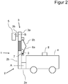
- the initial example of a holding device 1 according to the invention has a carrier element 2 and a holding element 3 that can be displaced relative to the carrier element.
- the carrier element 2 is designed for attachment to a vehicle 4, in the present case a tractor.
- the carrier element 2 has a vehicle mount 2a and a mast element 2b.
- the holding element 3 is designed to be a machine relative to the carrier element 2, in particular the mast element 2b to be arranged pivotable.
- the holding element 3 has a main element 3a and a pivot element 3b.
- a side view of the holding device 1 is shown in the use configuration: the holding device 1 is arranged on the vehicle 4 by means of the vehicle mount 2a.
- a machine 5 is arranged on the swivel element 3 b of the holding element 3.
- the mast element 2b is designed as a telescopic element with a telescopic area shown hatched, so that the retaining element 3 in Figure 1 can be moved vertically up or down.
- the holding element 2b is thus arranged displaceably in a straight line on the mast element 2b of the carrier element 2, wherein in Figure 1 the direction of displacement V is shown.
- the holding device has a path detector for detecting the displacement path of the holding element 3 relative to the carrier element 2:
- the path detector has a first arm 6a, a second arm 6b and an angle detector 7.
- the first arm 6a is arranged directly, without the interposition of further pivotable parts, pivotably on the mast element 2b of the carrier element 2 and on the second arm 6b.
- the second arm 6b is thus arranged directly, without the interposition of further pivotable elements, pivotably on the first arm 6a and pivotably on the main element 3a of the holding element 3.
- the angle detector 7 is arranged between the mast element 2b of the carrier element 2 and the first arm 6a in order to detect an angle ⁇ between the first arm 6a and the mast element 2b.
- the holding device 1 has a hydraulic cylinder which is connected to a hydraulic unit of the vehicle 4 in order to extend and retract the mast element 2b and thus to move the holding device 1 up and down.
- the holding device 1 has a control device 8 which is connected to the aforementioned hydraulic cylinder and to the angle detector 7.
- the control device 8 is designed to control the hydraulic cylinder when a distance is predefined in such a way that the working height of the machine 5 and the predefined distance change. If, for example, an opposite of the representation in Figure 1 If a greater working height is specified, the control device controls 8 the hydraulic cylinder in such a way that the mast element 2b is extended. This is in Figure 2 shown.
- Figure 2 shows the view according to Figure 1 across from Figure 1 telescopic mast element 2b extended by means of the hydraulic cylinder. As can be clearly seen, the angle ⁇ between the first arm 6a and mast element 2b is smaller compared to the lower working height according to FIG Figure 1 .
- the control device 8 calculates the respective working height from the measurement signals of the angle detector and can thus compare the actual working height with the specified target working height in order to carry out a control such that the machine 5 is driven to the desired working height.
- the machine 5 represents a cutting device for rows of grapevines, which is only shown schematically as a block.
- such cutting devices have an elongated structure with several rotating knives arranged one above the other, which are hydraulically driven.
- hydraulic lines are fed from the hydraulic unit of the vehicle 4 via the mast element 2b to the end of the first arm 6a facing the mast element 2b, along the first arm to the second arm, along the second arm to the end of the second arm facing the main element 3a of the main element 3a to the pivot element 3b and finally to the machine 5.
- the holding device has further hydraulic cylinders to pivot the mast element 2b relative to the vehicle bracket 2a about an axis A and further hydraulic cylinders to pivot the pivot element 3b about an axis B relative to the main element 3a.
- the pivot axes between the first arm and the second arm, the first arm and the mast element and the second arm and the main element are parallel and are perpendicular to a direction of travel of the vehicle 4 when driving straight ahead.
- Figures 1 and 2 are these axes of rotation thus perpendicular to the plane of the drawing
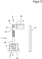
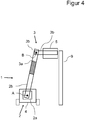
- Figures 3 and 4th these axes lie parallel to the plane of the drawing.
- first and second arm extends in a plane which is parallel to the direction of travel when driving straight ahead. Accordingly, the user's field of vision is only slightly restricted by the first arm 6a and the second arm 6b and the lines routed thereon, as in particular in FIG Figures 3 and 4th , which show a top view from the front, can be seen.
- the carrier device also has a mast angle detector which is arranged on the pivot axis A between the vehicle holder 2a and the mast element 2b. Furthermore, the device has a machine angle detector which is arranged on the pivot axis B between the pivot element 3B and the main element 3A. These detectors are also connected to the control device 8.
- the control device 8 pivots the mast element 2b relative to the vehicle bracket in the view according to FIG Figure 3 clockwise.
- the control device 8 pivots the pivot element 3b relative to the main element 3a counterclockwise, so that the rotational movement is compensated and the pivot element 3b remains in a horizontal position.
- This is possible by means of a regulation, since the respective angular positions can be determined by the control device 8 by means of the mast angle detector and machine angle detector.
- the pivoting movements are carried out by the aforementioned hydraulic cylinders under control of the control devices.
- the control device 8 is therefore additionally designed to compensate for a difference in height of the machine 5 when the mast element 2b is pivoted relative to the vehicle mount 2a and the pivoting element 3b is moved in a countermovement to the main element 3a, as described above, in that the mast element 2b is extended in the present case, ie a sliding movement of the main element 3a away from the vehicle mount 2a takes place.
- the distance of the displacement path is chosen so that in the end position according to Figure 4 the machine 5 is approached to the grapevine line 9, but at the same working height as in Figure 3 is located.
Landscapes
- Life Sciences & Earth Sciences (AREA)
- Environmental Sciences (AREA)
- Biodiversity & Conservation Biology (AREA)
- Ecology (AREA)
- Forests & Forestry (AREA)
- Engineering & Computer Science (AREA)
- Mechanical Engineering (AREA)
- Soil Sciences (AREA)
- Lifting Devices For Agricultural Implements (AREA)
- Agricultural Machines (AREA)
Description
- Die Erfindung betrifft eine Haltevorrichtung für eine Maschine zur Pflanzenbearbeitung gemäß Oberbegriff des Anspruchs 1 sowie ein Verfahren zum Steuern einer Haltevorrichtung für eine Maschine zur Pflanzenbearbeitung gemäß Oberbegriff des Anspruchs 9.
- Zur Pflanzenbearbeitung ist eine Vielzahl von Maschinen bekannt, welche beispielsweise ein Entlauben, ein Schneiden oder Besprühen der Pflanze ermöglichen. Solche Maschinen finden insbesondere im Obstbau und Weinbau Anwendung. Es ist hierbei häufig notwendig, die Lage der Maschine relativ zum Boden zu ändern, insbesondere, um eine gewünschte Arbeitshöhe zu erzielen.
- Es sind daher Haltevorrichtungen für solche Maschinen zur Pflanzenbearbeitung bekannt, welche ein Trägerelement zum Befestigen der Haltevorrichtung an einem Fahrzeug, beispielsweise einem Traktor, aufweisen. An dem Trägerelement ist eine Haltevorrichtung für eine Maschine zur Pflanzenbearbeitung mittels eines hydraulischen Zylinders entlang des Trägerelementes verschiebbar angeordnet. Mittels des hydraulischen Zylinders kann bei senkrecht stehendem Trägerelement die Maschine zur Pflanzenbearbeitung somit nach oben und unten verschoben werden, um eine gewünschte Arbeitshöhe zu erzielen. Solche Haltevorrichtungen sind aus
DE102016115934A1 undDE69912671T2 bekannt. - In
EP 0 898 877 A1 ist eine Haltevorrichtung mit einem Trägerelement und einem schwenkbar und verschiebbar an dem Trägerelement angeordneten Arm für eine Maschine beschrieben. - Der vorliegenden Erfindung liegt die Aufgabe zugrunde, die Steuermöglichkeiten solcher Haltevorrichtungen zu verbessern.
- Gelöst ist diese Aufgabe durch eine Haltevorrichtung gemäß Anspruch 1 sowie durch ein Verfahren zum Steuern einer Haltevorrichtung gemäß Anspruch 9. Vorteilhafte Ausgestaltungen finden sich in den abhängigen Unteransprüchen.
- Die erfindungsgemäße Haltevorrichtung ist bevorzugt zur Durchführung des erfindungsgemäßen Verfahrens ausgebildet, insbesondere einer vorteilhaften Ausführungsform hiervon. Das erfindungsgemäße Verfahren ist bevorzugt zur Durchführung mittels der erfindungsgemäßen Haltevorrichtung ausgebildet, insbesondere einer bevorzugten Ausführungsform hiervon.
- Die erfindungsgemäße Haltevorrichtung für eine Maschine zur Pflanzenbearbeitung weist ein Trägerelement zur Befestigung der Haltevorrichtung an einem Fahrzeug, insbesondere an einem Traktor, auf sowie ein relativ zu dem Trägerelement verschiebbares Halteelement, zum Anordnen der Maschine an dem Halteelement.
- Mittels der Haltevorrichtung kann somit eine Maschine mittelbar an dem Fahrzeug angeordnet werden und durch Verschieben des Halteelementes relativ zu dem Trägerelement ist die Maschine relativ zu dem Fahrzeug verschiebbar.
- Wesentlich ist, dass die Haltevorrichtung einen Wegdetektor zur Detektion eines Verschiebeweges des Halteelementes relativ zu dem Trägerelement aufweist. Der Detektor weist zumindest einen ersten und einen zweiten Arm sowie einen Winkeldetektor auf. Der erste Arm ist zumindest mittelbar schwenkbar an dem Trägerelement angeordnet, der zweite Arm ist zumindest mittelbar schwenkbar an dem ersten Arm und zumindest mittelbar schwenkbar an dem Halteelement angeordnet. Der Winkeldetektor ist derart angeordnet, um zumindest mittelbar eine Winkeländerung zwischen den beiden Armen, zwischen dem ersten Arm und dem Halteelement und/oder zwischen dem zweiten Arm und dem Halteelement zu detektieren. Der Winkeldetektor kann hierbei insbesondere an dem Trägerelement, dem ersten Arm, dem zweiten Arm und/oder der Haltevorrichtung angeordnet sein.
- Die Erfindung ist in der Erkenntnis des Anmelders begründet, dass die Detektion des Verschiebewegs zwischen Halteelemente und Trägerelement die Steuermöglichkeit einer solchen Haltevorrichtung erheblich verbessert und somit den Bedienungskomfort für den Benutzer und auch die Sicherheit erhöhen kann. Bei bisherigen Haltevorrichtungen wurde die Verschiebung zwischen Halteelement und Trägerelement manuell durch den Benutzer gesteuert und eine Arbeitshöhe manuell durch Sichtkontrolle eingestellt. Insbesondere bei Haltevorrichtungen, deren Trägerelement einen relativ zu dem Fahrzeug verschwenkbaren Mast aufweist, musste bei einem Verschwenken des Mastes bisher die Arbeitshöhe manuell durch Verschieben des Halteelementes relativ zu dem Trägerelement korrigiert werden.
- Eine Detektion des Verschiebewegs und/oder eine Änderung des Verschiebewegs bei Verschieben des Halteelements relativ zu dem Trägerelement erweitert die Steuermöglichkeiten für solch eine Haltevorrichtung jedoch erheblich, sodass Benutzungskomfort und Sicherheit erhöht werden können. Untersuchungen des Anmelders zeigen jedoch, dass die Verwendung von linearen Wegdetektoren zur Detektion des Verschiebeweges Nachteile aufweisen. So stellen solche Detektoren in der gewünschten Genauigkeit einen erheblichen Kostenfaktor dar. Darüber hinaus sind solche Detektoren aufgrund des Verschiebevorgangs anfällig für Verschmutzungen oder Beschädigungen.
- Die vorliegende Erfindung ist weiterhin auf der Kenntnis begründet, dass mittels dem ersten und zweiten Arm der erfindungsgemäßen Haltevorrichtung über eine Messung zumindest eine Winkeländerung durch den Winkeldetektor eine Bestimmung des Verschiebewegs zwischen Halteelement und Trägerelement möglich ist, wobei auf kostenaufwändige und störanfällige lineare Wegdetektoren verzichtet werden kann:
Der erste Arm ist zumindest mittelbar, d. h. ggf. über weitere Elemente, insbesondere ggf. über weitere schwenkbare Elemente, an dem Trägerelement angeordnet. Der zweite Arm ist zumindest mittelbar schwenkbar an dem ersten Arm und zumindest mittelbar schwenkbar an dem Halteelement angeordnet. Der Winkeldetektor ist derart angeordnet, dass mittels des Winkeldetektors eine Winkeländerung zumindest zwischen einem der nachfolgend genannten Paare erster Arm und Trägerelement; erster Arm und zweiter Arm; zweiter Arm und Halteelement gemessen werden kann. - Bevorzugt sind erster und zweiter Arm derart angeordnet, dass ein Verschieben des Halteelementes relativ zu dem Trägerelement stets Änderungen des Winkels bewirkt, welcher mittels des Winkeldetektors detektierbar ist.
- Bevorzugt ist die Haltevorrichtung derart ausgebildet, dass ein Verschieben des Halteelementes relativ zu dem Trägerelement eine Winkeländerung zwischen erstem Arm und Trägerelement, zwischen erstem und zweitem Arm und zwischen zweitem Arm und Halteelement bewirkt.
- Insbesondere ist es vorteilhaft, dass der erste Arm unmittelbar schwenkbar an dem Trägerelement, der zweite Arm unmittelbar schwenkbar an dem ersten Arm und der zweite Arm unmittelbar schwenkbar an dem Halteelement angeordnet ist. Vorteilhafterweise ist somit der erste Arm an dem Trägerelement sowie der zweite Arm an dem ersten Arm und dem Halteelement jeweils ohne Zwischenschaltung weiterer schwenkbarer Elemente angeordnet.
- Hierdurch ergibt sich ein konstruktiv einfacher Aufbau.
- Das Halteelement ist bevorzugt geradlinig verschiebbar an dem Trägerelement angeordnet. Hierdurch ergibt sich ein konstruktiv einfacher Aufbau. Insbesondere kann in einfacher Weise eine Arbeitshöhe durch geradliniges Verschieben des Trägerelementes an dem Halteelement erzielt werden. In einer vorteilhaften Ausführungsform weist das Trägerelement ein Teleskopelement auf und das Halteelement ist an einem ausfahrbaren Bereich, insbesondere einem Endbereich des Teleskopelementes angeordnet, so dass durch ausfahren des Teleskopelementes das Halteelement geradlinig relativ zu dem Trägerelement verschiebbar ist. Ebenso liegt es im Rahmen der Erfindung, das Haltelement entlang des Trägerelementes verschiebbar auszubilden, insbesondere mittels Gleit- und/oder Rollenlagerung.
- In einer vorteilhaften Ausführungsform ist an zumindest einem der Arme, bevorzugt an beiden Armen, insbesondere bevorzugt entlang beider Arme zumindest eine Leitung, insbesondere eine elektrische und/oder hydraulische Leitung zwischen Trägerelement und Halteelement geführt.
- Diese vorteilhafte Ausgestaltung ist in der Erkenntnis begründet, dass bei Haltevorrichtungen mit verschiebbaren Halteelementen, insbesondere mit geradlinig verschiebbaren Halteelementen typischerweise zumindest eine Leitung, meist eine Mehrzahl von Leitungen wie beispielsweise Hydraulikleitungen und/oder elektrische Leitungen, zu einer an dem Halteelement angeordneten Maschine geführt werden müssen. Bei Bewegen der Maschine mittels Verschieben des Halteelementes relativ zu dem Trägerelement ergibt sich die Aufgabe, mindestens eine Leitung einerseits sicher zu führen und andererseits eine Reibung oder andersartige hohe mechanische Belastung zu vermeiden. Weiterhin soll das Sichtfeld eines Benutzers möglichst gering eingeschränkt werden.
- In der zuvor genannten vorteilhaften Ausführungsform wird zumindest eine Leitung an zumindest einem der Arme, bevorzugt an beiden Armen, geführt. Dies weist den Vorteil auf, dass bei einem Verschieben des Halteelementes relativ zu dem Trägerelement zwar eine Winkeländerung zwischen den Armen und Trägerelement und Halteelement erfolgt, jedoch die Gesamtlänge der beiden Arme konstant ist. Eine Leitung, welche von dem Trägerelement entlang des ersten Armes zu dem zweiten Arm und entlang des zweiten Armes zu dem Halteelement geführt wird, muss somit nicht relativ zu den Armen verschoben werden, wenn das Halteelement relativ zu dem Trägerelement verschoben wird. Lediglich an den Punkten, an welchen die Arme schwenkbar aneinander oder an dem Trägerelement bzw. Halteelement gelagert sind, ändert sich der Biegewinkel der Leitung bei Verschieben des Halteelementes relativ zu dem Trägerelement. Eine solche Änderung des Biegewinkels kann jedoch in an sich bekannter Weise durch Biegungsreserven und/oder Biegeführungen hinsichtlich der Belastung der Leitung abgemildert werden, sodass in der beschriebenen bevorzugten Ausführungsform eine stabile, gegenüber äußeren Einflüssen, insbesondere Stößen, unanfällige Führung der Leitung möglich ist.
- Bevorzugt wird somit zumindest eine, bevorzugt mehrere Versorgungsleitungen für die Maschine entlang eines Armes, bevorzug entlang beider Arme geführt.
- Bevorzugt sind erster und zweiter Arm derart angeordnet, dass bei an dem Fahrzeug angeordnete Haltevorrichtungen die Arme sich in entlang der Fahrtrichtung bei Geradeausfahrt erstrecken. Hierdurch ist das Sichtfeld eines Benutzers durch die Arme sowie durch etwaige an den Armen angeordneten Leitungen nur geringfügig eingeschränkt. Vorteilhafterweise ist die Schwenkachse des ersten Arms zu dem Trägerelement parallel zu der Schwenkachse des ersten Arms zu dem zweiten Arm und parallel zu der Schwenkachse des zweiten Arms zu dem Halteelement. Insbesondere bevorzugt sind die vorgenannten Schwenkachsen derart gewählt, dass bei an dem Fahrzeug angeordnete Haltevorrichtungen bei Geradeausfahrt die Schwenkachsen in etwa quer, insbesondere bevorzugt senkrecht zur Fahrtrichtung liegen, weiter bevorzugt, dass die Schwenkachsen bei auf einer waagerechten Ebene stehendem Fahrzeug waagerecht liegen.
- Der Winkeldetektor ist bevorzugt zwischen Trägerelement und erstem Arm angeordnet, um eine Winkeländerung zwischen erstem Arm und Trägerelement zu messen. Hierdurch ergibt sich der Vorteil, dass bei einem Verschieben des Halteelementes relativ zu dem Trägerelement keine Verschiebung des Winkeldetektors erfolgt. Es ergeben sich somit weniger bewegte Teile und darüber hinaus ändert sich ein Zuleitungsweg von Leitungen zu dem Winkeldetektor, insbesondere von Signalleitungen bei Verschieben des Mastelementes relativ zu dem Trägerelement nicht, da bevorzugt die Steuereinheit ortsfest zu dem Trägerelement angeordnet ist, insbesondere ortsfest zu einem Fahrzeug, an welchem das Trägerelement angeordnet ist.
- In einer Benutzungskonfiguration ist die Haltevorrichtung an dem Fahrzeug angeordnet, insbesondere an einem Traktor und an der Haltevorrichtung ist an dem Halteelement eine Maschine angeordnet, insbesondere eine Maschine zur Pflanzenbearbeitung.
- Vorteilhafterweise ist die Haltevorrichtung derart ausgebildet, dass in Benutzungskonfigurationen die Arbeitshöhe der Maschine mittels Verschieben des Halteelementes relativ zu dem Trägerelement veränderbar ist.
- Der Wegdetektor ist vorteilhafterweise derart ausgebildet und angeordnet, dass zwischen der Ortsposition des Halteelementes entlang des Verschiebeweges und der Winkelstellung des Winkeldetektors ein linearer Zusammenhang besteht.
- Hierdurch kann in unaufwändiger Weise mittels einer Steuereinheit abhängig von einem Messsignal des Winkeldetektors ein Verschiebeweg und/oder eine Ortsposition des Halteelementes entlang des Verschiebeweges bestimmt werden.
- Der Verschiebeweg beträgt bevorzugt zumindest 50 cm, bevorzugt zumindest 70 cm. Vorteilhafterweise liegt der Verschiebeweg im Bereich 30 cm bis 200 cm, bevorzugt 40 cm bis 150 cm.
- Insbesondere bei solchen Verschiebewegen erweist sich die vorgenannte vorteilhafte Ausgestaltung als besonders vorteilhaft, bei welcher zumindest eine Leitung entlang der beiden Arme geführt ist.
- Vorteilhafterweise weist das Trägerelement eine Fahrzeughalterung zum Anordnen an dem Fahrzeug und ein schwenkbar an der Fahrzeughalterung angeordnetes Mastelement auf. Das Halteelement ist verschiebbar an dem Mastelement angeordnet. Das Trägerelement weist einen Mastwinkeldetektor auf, zum Detektieren eines Kippwinkels zwischen Fahrzeughalterung und Mastelement. In dieser vorteilhaften Ausführungsform ist in Benutzungskonfiguration somit das Mastelement schwenkbar zu der Fahrzeughalterung, wobei der Schwenkwinkel mittels des Mastwinkeldetektors detektierbar ist.
- Insbesondere ist das vorteilhaft, dass die Haltevorrichtung derart ausgebildet ist, dass in Benutzungskonfiguration die Schwenkachse zwischen Fahrzeughalterung und Mastelement parallel zur Fahrtrichtung bei Geradeausfahrt ist. Hierdurch kann durch ein Schwenken des Mastes die Maschine an eine Pflanzenzeile, insbesondere eine Weinrebenzeile, angenähert werden oder von der Pflanzenzeile entfernt werden.
- Das Halteelement ist bevorzugt ausgebildet, die Maschine relativ zu dem Trägerelement, insbesondere ein Mastelement des Trägerelementes schwenkbar anzuordnen. Weiterhin weist das Halteelement bevorzugt einen Maschinenwinkeldetektor zur Detektion eines Schwenkwinkels zwischen Trägerelement und der an dem Halteelement angeordneten Maschine, insbesondere zwischen einem Mastelement des Trägerelementes und der Maschine auf. In dieser vorteilhaften Ausgestaltung kann die Maschine somit in eine gewünschte Bearbeitungsrichtung gebracht werden, durch Ändern des Schwenkwinkels zwischen Trägerelement und Maschine. Durch den Maschinenwinkeldetektor ist auch dieser Schwenkwinkel detektierbar.
- Insbesondere ist es vorteilhaft, dass die Haltevorrichtung eine Steuereinheit aufweist, welche ausgebildet ist, in Benutzungskonfiguration abhängig von den Messdaten des Wegdetektors, des Mastwinkeldetektors und des Maschinenwinkeldetektors Schwenk- und Verschiebebewegungen der Haltevorrichtung derart zu steuern, dass eine geradlinige Bewegung der Maschine, insbesondere eine bei auf einer horizontalen Ebene stehendem Fahrzeug horizontale Bewegung der Maschine zu dem Fahrzeug hin und/oder von dem Fahrzeug weg ausführbar ist. In dieser vorteilhaften Ausführungsform können nun die Messsignale der drei vorbenannten Detektoren Wegdetektor, Mastwinkeldetektor und Maschinenwinkeldetektor verwendet werden, um in für den Benutzer einfacher Weise eine geradlinige Bewegung der Maschine durchzuführen. Insbesondere kann automatisch bei einem Verschwenken des Mastes relativ zu dem Fahrzeug eine durch das Verschwenken bewirkte Höhenänderung kompensiert werden, sodass sich die Arbeitshöhe der Maschine nicht ändert. Zusätzlich kann durch eine Schwenkbewegung in Gegenrichtung zwischen Maschine und Trägerelement die Schwenkbewegung durch Verschwenken des Mastes kompensiert werden, sodass sich nicht nur die Arbeitshöhe der Maschine nicht ändert, sondern auch die Arbeitsrichtung und Orientierung der Maschine relativ zu einer Pflanze unverändert bleibt.
- Vorteilhafterweise ist die Steuereinheit derart ausgebildet, dass der Benutzer durch einen einfachen Befehl die Maschine an eine sich neben dem Fahrzeug seitlich befindende Pflanzenreihe annähern oder von dieser entfernen kann, ohne dass sich die Arbeitshöhe und ohne dass sich die Arbeitsrichtung der Maschine ändert.
- Die vorliegende Erfindung ist weiterhin durch ein Verfahren zum Steuern einer Haltevorrichtung für eine Maschine zur Pflanzenbearbeitung gelöst, wobei die Maschine ein Trägerelement zur Befestigung der Haltevorrichtung an einem Fahrzeug und ein relativ zu dem Trägerelement verschiebbares Halteelement zum Anordnen der Maschine an dem Halteelement aufweist. Wesentlich ist, dass die Haltevorrichtung abhängig von Messsignalen eines Wegdetektors gesteuert wird, wobei der Wegdetektor zumindest einen ersten und einen zweiten Arm und einen Winkeldetektor aufweist, der erste Arm zumindest mittelbar schwenkbar an dem Trägerelement angeordnet ist, der zweite Arm zumindest mittelbar schwenkbar an dem ersten Arm und zumindest mittelbar schwenkbar an dem Halteelement angeordnet ist und mittels des Winkeldetektors zumindest mittelbar eine Winkeländerung zwischen den beiden Armen, zwischen dem ersten Arm und dem Halteelement und/oder zwischen dem zweiten Arm und dem Halteelement detektiert wird. Hierdurch ergeben sich die eingangs zu der erfindungsgemäßen Vorrichtung genannten Vorteile.
- Weitere vorteilhafte Merkmale und Ausführungsformen werden im Folgenden anhand von Ausführungsbeispielen und den Figuren erläutert. Dabei zeigt:
- Figur 1
- ein erstes Ausführungsbeispiel einer erfindungsgemäßen Haltevorrichtung in Seitenansicht in einer ersten Arbeitshöhe;
- Figur 2
- die Darstellung aus
Figur 1 in einer zweiten, demgegenüber größeren Arbeitshöhe; - Figur 3
- die Darstellung aus
Figur 1 in Draufsicht von vorne und - Figur 4
- die Darstellung aus
Figur 3 , wobei eine an der Haltevorrichtung angeordnete Maschine an eine Pflanzenreihe angenähert wurde. - Die Figuren zeigen schematische, nicht maßstabsgetreue Darstellungen. Gleiche Bezugszeichen in den Figuren zeigen gleiche oder gleichwirkende Elemente.
- Das Ausgangsbeispiel einer erfindungsgemäßen Haltevorrichtung 1 weist ein Trägerelement 2 und ein relativ zu dem Trägerelement verschiebbares Halteelement 3 auf.
- Das Trägerelement 2 ist zur Befestigung an einem Fahrzeug 4, vorliegend einem Traktor, ausgebildet. Das Trägerelement 2 weist eine Fahrzeughalterung 2a sowie ein Mastelement 2b auf. Das Halteelement 3 ist ausgebildet, eine Maschine relativ zu dem Trägerelement 2, insbesondere dem Mastelement 2b schwenkbar anzuordnen. Das Halteelement 3 weist hierzu ein Hauptelement 3a und ein Schwenkelement 3b auf. In
Figur 1 ist eine Seitenansicht der Haltevorrichtung 1 in Benutzungskonfiguration dargestellt: Die Haltevorrichtung 1 ist mittels der Fahrzeughalterung 2a an dem Fahrzeug 4 angeordnet. Eine Maschine 5 ist an dem Schwenkelement 3b des Halteelements 3 angeordnet. - Das Mastelement 2b ist vorliegend als Teleskopelement mit einem schraffiert dargestellten teleskopierbaren Bereich ausgebildet, sodass durch Ein- und Ausfahren des Mastelementes 2b das Halteelement 3 in
Figur 1 senkrecht nach oben oder nach unten bewegt werden kann. Das Halteelement 2b ist somit geradlinig verschiebbar an dem Mastelement 2b des Trägerelementes 2 angeordnet, wobei inFigur 1 die Verschiebungsrichtung V dargestellt ist. - Die Haltevorrichtung weist einen Wegdetektor zur Detektion des Verschiebewegs des Halteelements 3 relativ zu dem Trägerelement 2 auf: Der Wegdetektor weist einen ersten Arm 6a, einen zweiten Arm 6b und einen Winkeldetektor 7 auf.
- Der erste Arm 6a ist unmittelbar, ohne Zwischenschaltung weiterer verschwenkbarer Teile, schwenkbar an dem Mastelement 2b des Trägerelementes 2 sowie an dem zweiten Arm 6b angeordnet. Der zweite Arm 6b ist somit unmittelbar, ohne Zwischenschaltung weiterer verschwenkbarer Elemente, schwenkbar an dem ersten Arm 6a sowie schwenkbar an dem Hauptelement 3a des Halteelementes 3 angeordnet. Der Winkeldetektor 7 ist zwischen Mastelement 2b des Trägerelementes 2 und erstem Arm 6a angeordnet, um einen Winkel α zwischen erstem Arm 6a und Mastelement 2b zu detektieren. Die Haltevorrichtung 1 weist einen Hydraulikzylinder auf, welcher mit einem Hydraulikaggregat des Fahrzeugs 4 verbunden ist, um das Mastelement 2b aus- und einzufahren und somit die Haltevorrichtung 1 nach oben und nach unten zu verschieben.
- Die Haltevorrichtung 1 weist hierzu eine Steuervorrichtung 8 auf, welche mit dem vorgenannten Hydraulikzylinder und mit dem Winkeldetektor 7 verbunden ist. Die Steuervorrichtung 8 ist ausgebildet, um bei Vorgabe einer Wegstrecke den Hydraulikzylinder derart zu steuern, dass sich die Arbeitshöhe der Maschine 5 und die vorgegebene Wegstrecke ändert. Wird beispielsweise eine gegenüber der Darstellung in
Figur 1 größere Arbeitshöhe vorgegeben, so steuert die Steuervorrichtung 8 den Hydraulikzylinder derart, dass das Mastelement 2b ausgefahren wird. Dies ist inFigur 2 dargestellt. -
Figur 2 zeigt die Ansicht gemäßFigur 1 gegenüberFigur 1 mittels des Hydraulikzylinders ausgefahrenen teleskopischen Mastelement 2b. Wie deutlich sichtbar, ist der Winkel β zwischen erstem Arm 6a und Mastelement 2b kleiner gegenüber der niedrigeren Arbeitshöhe gemäßFigur 1 . - Aus den Messsignalen des Winkeldetektors berechnet die Steuervorrichtung 8 die jeweilige Arbeitshöhe und kann somit die tatsächliche Arbeitshöhe mit der vorgegebenen Soll-Arbeitshöhe vergleichen, um eine Steuerung derart durchzuführen, dass die Maschine 5 in die gewünschte Arbeitshöhe gefahren wird.
- Die Maschine 5 stellt eine Schneidevorrichtung für Weinrebezeilen dar, die lediglich schematisch als Block dargestellt ist. Typischerweise weisen solche Schneidvorrichtungen einen länglichen Aufbau mit mehreren übereinander angeordneten rotierenden Messern auf, welche hydraulisch angetrieben werden. Hierzu werden von der Hydraulikeinheit des Fahrzeugs 4 Hydraulikleitungen über das Mastelement 2b zu dem dem Mastelement 2b zugewandten Ende des ersten Armes 6a, entlang des ersten Armes zu dem zweiten Arm, entlang des zweiten Armes zu dem dem Hauptelement 3a zugewandten Ende des zweiten Armes, entlang des Hauptelementes 3a zu dem Schwenkelement 3b und schließlich zur Maschine 5 geführt.
- Wie ein Vergleich der
Figuren 1 und2 zeigt, ändert sich die Gesamtlänge dieser Wegstrecke nicht, lediglich die Biegung der Hydraulikleitungen an den Übergängen zwischen Mastelement 2b und erstem Arm, erstem Arm und zweitem Arm sowie zweitem Arm und Hauptelement 3a ändert sich. - Die Haltevorrichtung weist weitere Hydraulikzylinder auf, um das Mastelement 2b relativ zu der Fahrzeughalterung 2a um eine Achse A zu verschwenken und weitere Hydraulikzylinder, um das Schwenkelement 3b um eine Achse B relativ zu dem Hauptelement 3a zu schwenken. Die Schwenkachsen zwischen erstem Arm und zweitem Arm, erstem Arm und Mastelement sowie zweitem Arm und Hauptelement sind parallel und stehen senkrecht zu einer Fahrtrichtung des Fahrzeugs 4 bei Geradeausfahrt. In den
Figuren 1 und2 stehen diese Drehachsen somit senkrecht zur Zeichenebene, in denFiguren 3 und4 liegen diese Achsen parallel zur Zeichenebene. - Entsprechend erstrecken sich erster und zweiter Arm mit ihrer Längserstreckung in einer Ebene, die parallel zur Fahrtrichtung bei Geradeausfahrt liegt. Entsprechend ist das Sichtfeld des Benutzers durch den ersten Arm 6a und den zweiten Arm 6b sowie die daran geführten Leitungen nur geringfügig eingeschränkt, wie insbesondere in den
Figuren 3 und4 , welche eine Draufsicht von vorne zeigen, ersichtlich. - Die Wegmessung des Verschiebewegs zwischen Halteelement 3 und Trägerelement 2 ermöglicht jedoch nicht nur die Vorgabe einer gewünschten Arbeitshöhe, ebenso ist ein kartesisches Verfahren der Maschine 5 automatisiert möglich. Insbesondere kann die Maschine 5 einer Weinrebenzeile angenähert werden, wobei eine Steuerung automatisiert derart erfolgt, dass sich die Arbeitshöhe der Maschine 5 nicht ändert. Dies wird nachfolgend an den
Figuren 3 und4 erläutert:
InFigur 3 ist die Darstellung gemäßFigur 1 in Draufsicht von vorne gezeigt. Die Schwenkachsen A und B von Mastelement und Schwenkelement stehen somit senkrecht zur Zeichenebene. - Neben dem Fahrzeug 4 befindet sich eine Weinrebenzeile 9. Der Benutzer gibt nun einen Steuerbefehl, beispielsweise "Annähern" oder "Joystick links" mittels der Steuervorrichtung 8 vor, um die Maschine 5 durch ein Schwenken des Mastelementes 2b relativ zur Fahrzeughalterung 2a und somit auch relativ zu dem Fahrzeug 4 an die Weinrebenzeile 9 anzunähern. Die Trägervorrichtung weist zusätzlich einen Mastwinkeldetektor auf, welcher an der Schwenkachse A zwischen Fahrzeughalterung 2a und Mastelement 2b angeordnet ist. Weiterhin weist die Vorrichtung einen Maschinenwinkeldetektor auf, welcher an der Schwenkachse B zwischen Schwenkelement 3B und Hauptelement 3A angeordnet ist. Auch diese Detektoren sind mit der Steuervorrichtung 8 verbunden.
- Auf den vorgenannten Steuerbefehl des Benutzers hin schwenkt die Steuervorrichtung 8 das Mastelement 2b relativ zur Fahrzeughalterung in der Ansicht gemäß
Figur 3 im Uhrzeigersinn. Gleichzeitig schwenkt die Steuervorrichtung 8 das Schwenkelement 3b relativ zu dem Hauptelement 3a gegen den Uhrzeigersinn, sodass die Drehbewegung kompensiert wird und das Schwenkelement 3b in einer waagerechten Stellung verbleibt. Dies ist mittels einer Regelung möglich, da die jeweiligen Winkelstellungen mittels Mastwinkeldetektor und Maschinenwinkeldetektor durch die Steuervorrichtung 8 bestimmt werden können. Die Schwenkbewegungen werden durch die zuvor genannten hydraulischen Zylinder mittels Steuerung durch die Steuervorrichtungen ausgeführt. - Durch die vorgenannte Bewegung würde sich jedoch die Arbeitshöhe der Maschine 5 ändern. Die Steuervorrichtung 8 ist daher zusätzlich ausgebildet, einen Höhenunterschied der Maschine 5 bei Schwenken des Mastelementes 2b relativ zu der Fahrzeughalterung 2a und entsprechender Gegenbewegung des Schwenkelementes 3b zu dem Hauptelement 3a, wie zuvor beschrieben, zu kompensieren, indem vorliegend das Mastelement 2b ausgefahren wird, d. h. eine Verschiebebewegung des Hauptelementes 3a von der Fahrzeughalterung 2a weg erfolgt. Die Strecke des Verschiebewegs wird derart gewählt, dass in der Endstellung gemäß
Figur 4 die Maschine 5 an die Weinrebenzeile 9 angenähert ist, jedoch sich in unveränderter Arbeitshöhe wie auch inFigur 3 befindet. -
- 1
- Haltevorrichtung
- 2
- Trägerelement
- 2a
- Fahrzeughalterung
- 2b
- Mastelement
- 3
- Halteelement
- 3a
- Hauptelement
- 3b
- Schwenkelement
- 4
- Fahrzeug
- 5
- Maschine
- 6a
- erster Arm
- 6b
- zweiter Arm
- 7
- Winkeldetektor
- 8
- Steuervorrichtung
- 9
- Weinrebenzeile
Claims (9)
- Haltevorrichtung (1) für eine Maschine (5) zur Pflanzenbearbeitung, mit einem Trägerelement (2), zur Befestigung der Haltevorrichtung (1) an einem Fahrzeug (4) und
einem relativ zu dem Trägerelement (2) verschiebbaren Halteelement (3), zum Anordnen der Maschine (5) an dem Halteelement (3),
dadurch gekennzeichnet,
dass die Haltevorrichtung (1) einen Wegdetektor zu Detektion eines Verschiebeweges des Halteelements relativ zu dem Trägerelement (2) aufweist, wobei der Wegdetektor zumindest einen ersten und einen zweiten Arm (6a, 6b) und einen Winkeldetektor (7) aufweist, der erste Arm (6a) zumindest mittelbar schwenkbar an dem Trägerelement (2) angeordnet ist, der zweite (6b) Arm zumindest mittelbar schwenkbar an dem ersten Arm und zumindest mittelbar schwenkbar an dem Halteelement (3) angeordnet ist und
der Winkeldetektor (7) derart angeordnet ist, um zumindest mittelbar eine Winkeländerung zwischen den beiden Armen (6a, 6b), zwischen dem ersten Arm (6a) und dem Trägerelement (2) und/oder zwischen dem zweiten (6b) Arm und dem Halteelement (3) zu detektieren. - Haltevorrichtung (1) nach Anspruch 1,
dadurch gekennzeichnet,
dass an zumindest einem der Arme, bevorzugt an beiden Armen, insbesondere bevorzugt entlang beider Arme zumindest eine Leitung, insbesondere eine elektrische und/oder hydraulische Leitung zwischen Trägerelement (2) und Halteelement (3) geführt ist. - Haltevorrichtung (1) nach einem der vorangegangenen Ansprüche,
dadurch gekennzeichnet,
dass das Halteelement (3) geradlinig verschiebbar an dem Trägerelement (2) angeordnet ist. - Haltevorrichtung (1) nach einem der vorangegangenen Ansprüche,
dadurch gekennzeichnet,
dass der erste Arm an dem Trägerelement (2) sowie der zweite Arm an dem ersten Arm und dem Halteelement (3) jeweils ohne Zwischenschaltung weiterer schwenkbarer Elemente angeordnet ist. - Haltevorrichtung (1) nach einem der vorangegangenen Ansprüche,
dadurch gekennzeichnet,
dass der Winkeldetektor (7) zwischen Trägerelement (2) und erstem Arm angeordnet ist, um eine Winkeländerung zwischen erstem Arm Trägerelement (2) zu messen. - Haltevorrichtung (1) nach einem der vorangegangenen Ansprüche,
dadurch gekennzeichnet,
dass der Wegdetektor derart ausgebildet und angeordnet ist, zwischen der Ortsposition des Halteelementes entlang des Verschiebeweges und der Winkelstellung des Winkeldetektors ein linearer Zusammenhang besteht. - Haltevorrichtung (1) nach einem der vorangegangenen Ansprüche,
dadurch gekennzeichnet,
dass der Verschiebeweg zumindest 50 cm, bevorzugt zumindest Hub 70 cm beträgt und/oder dass der Verschiebeweg im Bereich 30 cm bis 200 cm, bevorzugt 40 cm bis 150 cm liegt. - Haltevorrichtung (1) nach einem der vorangegangenen Ansprüche,
dadurch gekennzeichnet,
dass das Trägerelement (2) eine Fahrzeughalterung (2a) zum Anordnen an dem Fahrzeug (4) und ein schwenkbar an der Fahrzeughalterung (2a) angeordnetes Mastelement (2b) aufweisen, wobei das Halteelement (3) verschiebbar an dem Mastelement (2b) angeordnet ist und dass das Trägerelement (2) einen Mastwinkeldetektor aufweist, zum Detektieren eines Schwenkwinkels zwischen Fahrzeughalterung (2a) und Mastelement (2b). - Verfahren zum Steuern einer Haltevorrichtung (1) für eine Maschine (5) zur Pflanzenbearbeitung, mit einem Trägerelement (2), zur Befestigung der Haltevorrichtung (1) an einem Fahrzeug (4) und einem relativ zu dem Trägerelement (2) verschiebbaren Halteelement (3), zum Anordnen der Maschine (5) an dem Halteelement (3),
dadurch gekennzeichnet,
dass die Haltevorrichtung (1) abhängig von Messsignalen eines Wegdetektors gesteuert wird, wobei der Wegdetektor zumindest einen ersten und einen zweiten Arm (6a, 6b) und einen Winkeldetektor (7) aufweist, der erste Arm (6a) zumindest mittelbar schwenkbar an dem Trägerelement (2) angeordnet ist, der zweite Arm (6b) zumindest mittelbar schwenkbar an dem ersten Arm (6a) und zumindest mittelbar schwenkbar an dem Halteelement (3) angeordnet ist und
mittels des Winkeldetektors (7) zumindest mittelbar eine Winkeländerung zwischen den beiden Armen (6a, 6b), zwischen dem ersten Arm (6a) und dem Halteelement (3) und/oder zwischen dem zweiten Arm (6b) und dem Halteelement (3) detektiert wird.
Applications Claiming Priority (1)
| Application Number | Priority Date | Filing Date | Title |
|---|---|---|---|
| DE102018112365.5A DE102018112365B3 (de) | 2018-05-23 | 2018-05-23 | Haltevorrichtung für eine Maschine zur Pflanzenbearbeitung und Verfahren zum Steuern solch einer Haltevorrichtung |
Publications (2)
| Publication Number | Publication Date |
|---|---|
| EP3571909A1 EP3571909A1 (de) | 2019-11-27 |
| EP3571909B1 true EP3571909B1 (de) | 2021-01-27 |
Family
ID=66589294
Family Applications (1)
| Application Number | Title | Priority Date | Filing Date |
|---|---|---|---|
| EP19174841.7A Active EP3571909B1 (de) | 2018-05-23 | 2019-05-16 | Haltevorrichtung für eine maschine zur pflanzenbearbeitung und verfahren zum steuern solch einer haltevorrichtung |
Country Status (2)
| Country | Link |
|---|---|
| EP (1) | EP3571909B1 (de) |
| DE (1) | DE102018112365B3 (de) |
Family Cites Families (7)
| Publication number | Priority date | Publication date | Assignee | Title |
|---|---|---|---|---|
| GB2249011B (en) | 1990-10-27 | 1994-02-16 | Bomford Turner Ltd | Improvements in mowers. |
| EP0898877B1 (de) * | 1997-08-21 | 2003-04-02 | Industrie et Nature de Navarre (I2N), Société Anonyme | Vorrichtung zum Entlauben von Reben |
| PT951813E (pt) | 1998-04-24 | 2004-04-30 | Binger France Sarl | Dispositivo de suporte de uma maquina utilizavel em especial na agricultura na arboricultura e na viticultura |
| DE102007020801A1 (de) | 2007-05-03 | 2008-11-06 | Herder B.V. | In der Höhe einstellbare Landbearbeitungseinrichtung |
| DE102010007276A1 (de) * | 2010-02-08 | 2011-08-11 | ERO-Gerätebau GmbH, 55469 | Steuervorrichtung und Verfahren zur Steuerung einer an einem Fahrzeug anordbaren Haltevorrichtung für eine Maschine zur Pflanzenbearbeitung |
| JP6068429B2 (ja) | 2014-12-25 | 2017-01-25 | ファナック株式会社 | ロボット識別システム |
| DE102016115934B4 (de) | 2016-08-26 | 2020-12-03 | ERO - Gerätebau GmbH | Haltevorrichtung für eine Maschine zur Pflanzenbearbeitung und Verfahren zum Betreiben einer Haltevorrichtung für eine Maschine zur Pflanzenbearbeitung |
-
2018
- 2018-05-23 DE DE102018112365.5A patent/DE102018112365B3/de not_active Expired - Fee Related
-
2019
- 2019-05-16 EP EP19174841.7A patent/EP3571909B1/de active Active
Non-Patent Citations (1)
| Title |
|---|
| None * |
Also Published As
| Publication number | Publication date |
|---|---|
| DE102018112365B3 (de) | 2019-10-10 |
| EP3571909A1 (de) | 2019-11-27 |
Similar Documents
| Publication | Publication Date | Title |
|---|---|---|
| EP3335532B1 (de) | Zinkenstriegel | |
| DE3604519C2 (de) | ||
| DE2001542C3 (de) | Fahrbare Einrichtung zur Überwachung und/oder Korrektur der Lage eines Gleises | |
| DE1807653A1 (de) | Oberflaechenbearbeitungsmaschine mit Niveau- und Neigungsregelung | |
| EP0215142A1 (de) | Halmteiler für landwirtschaftliche Maschinen | |
| DE102014113448A1 (de) | Zugfahrzeug und Anhängevorrichtung für ein Anbaugerät | |
| EP1407653A2 (de) | Vorrichtung zum Regeln der Position eines Anbaugeräts relativ zu einem Trägerfahrzeug | |
| EP3772265A1 (de) | Hackvorrichtung | |
| DE102019125553A1 (de) | Bewegliche bedienerstation für verbesserte sicht | |
| DE2265142C3 (de) | Vorrichtung zum Steuern der Lenkung eines Fahrzeugs | |
| DE2815228B2 (de) | ||
| EP3417685B1 (de) | Verfahren zur bestimmung einer physikalischen grösse eines oberlenkers | |
| EP2950040B1 (de) | Verfahren zur unterstützung eines fahrers eines nutzfahrzeug-gespanns und nutzfahrzeug-gespann mit einem fahrerassistenzsystem | |
| EP3571909B1 (de) | Haltevorrichtung für eine maschine zur pflanzenbearbeitung und verfahren zum steuern solch einer haltevorrichtung | |
| EP4052550B1 (de) | Seitenhangausgleichsvorrichtung für den weinanbau | |
| DE69107751T2 (de) | Elektronische Vorrichtung zum Steuern der Arbeitstiefe und des Hebens eines Aufsatteldrehpfluges. | |
| EP3243372A1 (de) | Verfahren zum einstellen eines schnittwinkels eines an einer selbstfahrenden erntemaschine angeordneten vorsatzgerätes | |
| EP3735810B1 (de) | Kopplungsvorrichtung für einen kraftheber | |
| EP0012997B1 (de) | Drehpflug | |
| EP2394501B1 (de) | Steuervorrichtung und Verfahren zur Steuerung einer an einem Fahrzeug anordbaren Haltevorrichtung für eine Maschine zur Pflanzenbearbeitung | |
| EP4275463A1 (de) | Landwirtschaftliches arbeitsgerät | |
| DE102018107406A1 (de) | Erntevorsatzgerät | |
| DE2703221C2 (de) | Bodenbearbeitungsgerät | |
| DE102022111876A1 (de) | Bearbeitungssystem, insbesondere für den Einsatz im Wein- und Obstbau | |
| DE102024112871A1 (de) | Verfahren zum Betreiben eines an einer Aufnahmevorrichtung eines Mähdreschers angeordneten Vorsatzgerätes sowie selbstfahrender Mähdrescher |
Legal Events
| Date | Code | Title | Description |
|---|---|---|---|
| PUAI | Public reference made under article 153(3) epc to a published international application that has entered the european phase |
Free format text: ORIGINAL CODE: 0009012 |
|
| STAA | Information on the status of an ep patent application or granted ep patent |
Free format text: STATUS: THE APPLICATION HAS BEEN PUBLISHED |
|
| AK | Designated contracting states |
Kind code of ref document: A1 Designated state(s): AL AT BE BG CH CY CZ DE DK EE ES FI FR GB GR HR HU IE IS IT LI LT LU LV MC MK MT NL NO PL PT RO RS SE SI SK SM TR |
|
| AX | Request for extension of the european patent |
Extension state: BA ME |
|
| STAA | Information on the status of an ep patent application or granted ep patent |
Free format text: STATUS: REQUEST FOR EXAMINATION WAS MADE |
|
| 17P | Request for examination filed |
Effective date: 20191209 |
|
| RBV | Designated contracting states (corrected) |
Designated state(s): AL AT BE BG CH CY CZ DE DK EE ES FI FR GB GR HR HU IE IS IT LI LT LU LV MC MK MT NL NO PL PT RO RS SE SI SK SM TR |
|
| GRAP | Despatch of communication of intention to grant a patent |
Free format text: ORIGINAL CODE: EPIDOSNIGR1 |
|
| STAA | Information on the status of an ep patent application or granted ep patent |
Free format text: STATUS: GRANT OF PATENT IS INTENDED |
|
| INTG | Intention to grant announced |
Effective date: 20201005 |
|
| GRAS | Grant fee paid |
Free format text: ORIGINAL CODE: EPIDOSNIGR3 |
|
| GRAA | (expected) grant |
Free format text: ORIGINAL CODE: 0009210 |
|
| STAA | Information on the status of an ep patent application or granted ep patent |
Free format text: STATUS: THE PATENT HAS BEEN GRANTED |
|
| AK | Designated contracting states |
Kind code of ref document: B1 Designated state(s): AL AT BE BG CH CY CZ DE DK EE ES FI FR GB GR HR HU IE IS IT LI LT LU LV MC MK MT NL NO PL PT RO RS SE SI SK SM TR |
|
| REG | Reference to a national code |
Ref country code: GB Ref legal event code: FG4D Free format text: NOT ENGLISH |
|
| REG | Reference to a national code |
Ref country code: CH Ref legal event code: EP |
|
| REG | Reference to a national code |
Ref country code: AT Ref legal event code: REF Ref document number: 1357489 Country of ref document: AT Kind code of ref document: T Effective date: 20210215 |
|
| REG | Reference to a national code |
Ref country code: IE Ref legal event code: FG4D Free format text: LANGUAGE OF EP DOCUMENT: GERMAN |
|
| REG | Reference to a national code |
Ref country code: DE Ref legal event code: R096 Ref document number: 502019000761 Country of ref document: DE |
|
| REG | Reference to a national code |
Ref country code: NL Ref legal event code: MP Effective date: 20210127 |
|
| REG | Reference to a national code |
Ref country code: LT Ref legal event code: MG9D |
|
| PG25 | Lapsed in a contracting state [announced via postgrant information from national office to epo] |
Ref country code: PT Free format text: LAPSE BECAUSE OF FAILURE TO SUBMIT A TRANSLATION OF THE DESCRIPTION OR TO PAY THE FEE WITHIN THE PRESCRIBED TIME-LIMIT Effective date: 20210527 Ref country code: NO Free format text: LAPSE BECAUSE OF FAILURE TO SUBMIT A TRANSLATION OF THE DESCRIPTION OR TO PAY THE FEE WITHIN THE PRESCRIBED TIME-LIMIT Effective date: 20210427 Ref country code: LT Free format text: LAPSE BECAUSE OF FAILURE TO SUBMIT A TRANSLATION OF THE DESCRIPTION OR TO PAY THE FEE WITHIN THE PRESCRIBED TIME-LIMIT Effective date: 20210127 Ref country code: BG Free format text: LAPSE BECAUSE OF FAILURE TO SUBMIT A TRANSLATION OF THE DESCRIPTION OR TO PAY THE FEE WITHIN THE PRESCRIBED TIME-LIMIT Effective date: 20210427 Ref country code: FI Free format text: LAPSE BECAUSE OF FAILURE TO SUBMIT A TRANSLATION OF THE DESCRIPTION OR TO PAY THE FEE WITHIN THE PRESCRIBED TIME-LIMIT Effective date: 20210127 Ref country code: HR Free format text: LAPSE BECAUSE OF FAILURE TO SUBMIT A TRANSLATION OF THE DESCRIPTION OR TO PAY THE FEE WITHIN THE PRESCRIBED TIME-LIMIT Effective date: 20210127 Ref country code: GR Free format text: LAPSE BECAUSE OF FAILURE TO SUBMIT A TRANSLATION OF THE DESCRIPTION OR TO PAY THE FEE WITHIN THE PRESCRIBED TIME-LIMIT Effective date: 20210428 |
|
| PG25 | Lapsed in a contracting state [announced via postgrant information from national office to epo] |
Ref country code: PL Free format text: LAPSE BECAUSE OF FAILURE TO SUBMIT A TRANSLATION OF THE DESCRIPTION OR TO PAY THE FEE WITHIN THE PRESCRIBED TIME-LIMIT Effective date: 20210127 Ref country code: LV Free format text: LAPSE BECAUSE OF FAILURE TO SUBMIT A TRANSLATION OF THE DESCRIPTION OR TO PAY THE FEE WITHIN THE PRESCRIBED TIME-LIMIT Effective date: 20210127 Ref country code: RS Free format text: LAPSE BECAUSE OF FAILURE TO SUBMIT A TRANSLATION OF THE DESCRIPTION OR TO PAY THE FEE WITHIN THE PRESCRIBED TIME-LIMIT Effective date: 20210127 Ref country code: SE Free format text: LAPSE BECAUSE OF FAILURE TO SUBMIT A TRANSLATION OF THE DESCRIPTION OR TO PAY THE FEE WITHIN THE PRESCRIBED TIME-LIMIT Effective date: 20210127 |
|
| PG25 | Lapsed in a contracting state [announced via postgrant information from national office to epo] |
Ref country code: IS Free format text: LAPSE BECAUSE OF FAILURE TO SUBMIT A TRANSLATION OF THE DESCRIPTION OR TO PAY THE FEE WITHIN THE PRESCRIBED TIME-LIMIT Effective date: 20210527 |
|
| REG | Reference to a national code |
Ref country code: DE Ref legal event code: R097 Ref document number: 502019000761 Country of ref document: DE |
|
| PG25 | Lapsed in a contracting state [announced via postgrant information from national office to epo] |
Ref country code: EE Free format text: LAPSE BECAUSE OF FAILURE TO SUBMIT A TRANSLATION OF THE DESCRIPTION OR TO PAY THE FEE WITHIN THE PRESCRIBED TIME-LIMIT Effective date: 20210127 Ref country code: CZ Free format text: LAPSE BECAUSE OF FAILURE TO SUBMIT A TRANSLATION OF THE DESCRIPTION OR TO PAY THE FEE WITHIN THE PRESCRIBED TIME-LIMIT Effective date: 20210127 Ref country code: SM Free format text: LAPSE BECAUSE OF FAILURE TO SUBMIT A TRANSLATION OF THE DESCRIPTION OR TO PAY THE FEE WITHIN THE PRESCRIBED TIME-LIMIT Effective date: 20210127 |
|
| PG25 | Lapsed in a contracting state [announced via postgrant information from national office to epo] |
Ref country code: DK Free format text: LAPSE BECAUSE OF FAILURE TO SUBMIT A TRANSLATION OF THE DESCRIPTION OR TO PAY THE FEE WITHIN THE PRESCRIBED TIME-LIMIT Effective date: 20210127 Ref country code: SK Free format text: LAPSE BECAUSE OF FAILURE TO SUBMIT A TRANSLATION OF THE DESCRIPTION OR TO PAY THE FEE WITHIN THE PRESCRIBED TIME-LIMIT Effective date: 20210127 Ref country code: RO Free format text: LAPSE BECAUSE OF FAILURE TO SUBMIT A TRANSLATION OF THE DESCRIPTION OR TO PAY THE FEE WITHIN THE PRESCRIBED TIME-LIMIT Effective date: 20210127 |
|
| PLBE | No opposition filed within time limit |
Free format text: ORIGINAL CODE: 0009261 |
|
| STAA | Information on the status of an ep patent application or granted ep patent |
Free format text: STATUS: NO OPPOSITION FILED WITHIN TIME LIMIT |
|
| 26N | No opposition filed |
Effective date: 20211028 |
|
| PG25 | Lapsed in a contracting state [announced via postgrant information from national office to epo] |
Ref country code: ES Free format text: LAPSE BECAUSE OF FAILURE TO SUBMIT A TRANSLATION OF THE DESCRIPTION OR TO PAY THE FEE WITHIN THE PRESCRIBED TIME-LIMIT Effective date: 20210127 Ref country code: MC Free format text: LAPSE BECAUSE OF FAILURE TO SUBMIT A TRANSLATION OF THE DESCRIPTION OR TO PAY THE FEE WITHIN THE PRESCRIBED TIME-LIMIT Effective date: 20210127 Ref country code: LU Free format text: LAPSE BECAUSE OF NON-PAYMENT OF DUE FEES Effective date: 20210516 Ref country code: AL Free format text: LAPSE BECAUSE OF FAILURE TO SUBMIT A TRANSLATION OF THE DESCRIPTION OR TO PAY THE FEE WITHIN THE PRESCRIBED TIME-LIMIT Effective date: 20210127 |
|
| REG | Reference to a national code |
Ref country code: BE Ref legal event code: MM Effective date: 20210531 |
|
| PG25 | Lapsed in a contracting state [announced via postgrant information from national office to epo] |
Ref country code: SI Free format text: LAPSE BECAUSE OF FAILURE TO SUBMIT A TRANSLATION OF THE DESCRIPTION OR TO PAY THE FEE WITHIN THE PRESCRIBED TIME-LIMIT Effective date: 20210127 |
|
| PG25 | Lapsed in a contracting state [announced via postgrant information from national office to epo] |
Ref country code: IE Free format text: LAPSE BECAUSE OF NON-PAYMENT OF DUE FEES Effective date: 20210516 |
|
| PG25 | Lapsed in a contracting state [announced via postgrant information from national office to epo] |
Ref country code: IS Free format text: LAPSE BECAUSE OF FAILURE TO SUBMIT A TRANSLATION OF THE DESCRIPTION OR TO PAY THE FEE WITHIN THE PRESCRIBED TIME-LIMIT Effective date: 20210527 |
|
| PG25 | Lapsed in a contracting state [announced via postgrant information from national office to epo] |
Ref country code: BE Free format text: LAPSE BECAUSE OF NON-PAYMENT OF DUE FEES Effective date: 20210531 |
|
| REG | Reference to a national code |
Ref country code: CH Ref legal event code: PL |
|
| PG25 | Lapsed in a contracting state [announced via postgrant information from national office to epo] |
Ref country code: LI Free format text: LAPSE BECAUSE OF NON-PAYMENT OF DUE FEES Effective date: 20220531 Ref country code: CH Free format text: LAPSE BECAUSE OF NON-PAYMENT OF DUE FEES Effective date: 20220531 |
|
| P01 | Opt-out of the competence of the unified patent court (upc) registered |
Effective date: 20230515 |
|
| PG25 | Lapsed in a contracting state [announced via postgrant information from national office to epo] |
Ref country code: NL Free format text: LAPSE BECAUSE OF NON-PAYMENT OF DUE FEES Effective date: 20210127 Ref country code: CY Free format text: LAPSE BECAUSE OF FAILURE TO SUBMIT A TRANSLATION OF THE DESCRIPTION OR TO PAY THE FEE WITHIN THE PRESCRIBED TIME-LIMIT Effective date: 20210127 |
|
| PG25 | Lapsed in a contracting state [announced via postgrant information from national office to epo] |
Ref country code: HU Free format text: LAPSE BECAUSE OF FAILURE TO SUBMIT A TRANSLATION OF THE DESCRIPTION OR TO PAY THE FEE WITHIN THE PRESCRIBED TIME-LIMIT; INVALID AB INITIO Effective date: 20190516 |
|
| GBPC | Gb: european patent ceased through non-payment of renewal fee |
Effective date: 20230516 |
|
| PG25 | Lapsed in a contracting state [announced via postgrant information from national office to epo] |
Ref country code: MK Free format text: LAPSE BECAUSE OF FAILURE TO SUBMIT A TRANSLATION OF THE DESCRIPTION OR TO PAY THE FEE WITHIN THE PRESCRIBED TIME-LIMIT Effective date: 20210127 Ref country code: GB Free format text: LAPSE BECAUSE OF NON-PAYMENT OF DUE FEES Effective date: 20230516 |
|
| PG25 | Lapsed in a contracting state [announced via postgrant information from national office to epo] |
Ref country code: TR Free format text: LAPSE BECAUSE OF FAILURE TO SUBMIT A TRANSLATION OF THE DESCRIPTION OR TO PAY THE FEE WITHIN THE PRESCRIBED TIME-LIMIT Effective date: 20210127 |
|
| PG25 | Lapsed in a contracting state [announced via postgrant information from national office to epo] |
Ref country code: MT Free format text: LAPSE BECAUSE OF FAILURE TO SUBMIT A TRANSLATION OF THE DESCRIPTION OR TO PAY THE FEE WITHIN THE PRESCRIBED TIME-LIMIT Effective date: 20210127 |
|
| PGFP | Annual fee paid to national office [announced via postgrant information from national office to epo] |
Ref country code: DE Payment date: 20250317 Year of fee payment: 7 |
|
| PGFP | Annual fee paid to national office [announced via postgrant information from national office to epo] |
Ref country code: IT Payment date: 20250530 Year of fee payment: 7 |
|
| PGFP | Annual fee paid to national office [announced via postgrant information from national office to epo] |
Ref country code: FR Payment date: 20250526 Year of fee payment: 7 |
|
| PGFP | Annual fee paid to national office [announced via postgrant information from national office to epo] |
Ref country code: AT Payment date: 20250519 Year of fee payment: 7 |