EP3571909B1 - Dispositif de maintien pour une machine de traitement de plantes et procédé de commande d'un tel dispositif de maintien - Google Patents
Dispositif de maintien pour une machine de traitement de plantes et procédé de commande d'un tel dispositif de maintien Download PDFInfo
- Publication number
- EP3571909B1 EP3571909B1 EP19174841.7A EP19174841A EP3571909B1 EP 3571909 B1 EP3571909 B1 EP 3571909B1 EP 19174841 A EP19174841 A EP 19174841A EP 3571909 B1 EP3571909 B1 EP 3571909B1
- Authority
- EP
- European Patent Office
- Prior art keywords
- arm
- holding
- holding device
- carrier element
- machine
- Prior art date
- Legal status (The legal status is an assumption and is not a legal conclusion. Google has not performed a legal analysis and makes no representation as to the accuracy of the status listed.)
- Active
Links
Images

Classifications
-
- A—HUMAN NECESSITIES
- A01—AGRICULTURE; FORESTRY; ANIMAL HUSBANDRY; HUNTING; TRAPPING; FISHING
- A01B—SOIL WORKING IN AGRICULTURE OR FORESTRY; PARTS, DETAILS, OR ACCESSORIES OF AGRICULTURAL MACHINES OR IMPLEMENTS, IN GENERAL
- A01B63/00—Lifting or adjusting devices or arrangements for agricultural machines or implements
- A01B63/002—Devices for adjusting or regulating the position of tools or wheels
- A01B63/008—Vertical adjustment of tools
-
- A—HUMAN NECESSITIES
- A01—AGRICULTURE; FORESTRY; ANIMAL HUSBANDRY; HUNTING; TRAPPING; FISHING
- A01G—HORTICULTURE; CULTIVATION OF VEGETABLES, FLOWERS, RICE, FRUIT, VINES, HOPS OR SEAWEED; FORESTRY; WATERING
- A01G3/00—Cutting implements specially adapted for horticultural purposes; Delimbing standing trees
- A01G3/04—Apparatus for trimming hedges, e.g. hedge shears
- A01G3/0417—Guiding frames for trimming hedges
-
- A—HUMAN NECESSITIES
- A01—AGRICULTURE; FORESTRY; ANIMAL HUSBANDRY; HUNTING; TRAPPING; FISHING
- A01G—HORTICULTURE; CULTIVATION OF VEGETABLES, FLOWERS, RICE, FRUIT, VINES, HOPS OR SEAWEED; FORESTRY; WATERING
- A01G3/00—Cutting implements specially adapted for horticultural purposes; Delimbing standing trees
- A01G3/04—Apparatus for trimming hedges, e.g. hedge shears
- A01G2003/0443—Apparatus for trimming hedges, e.g. hedge shears with height-adjustable platforms
Definitions
- the invention relates to a holding device for a machine for plant cultivation according to the preamble of claim 1 and a method for controlling a holding device for a machine for plant cultivation according to the preamble of claim 9.
- a large number of machines are known for cultivating plants which, for example, allow defoliation, cutting or spraying of the plant. Such machines are used in particular in fruit growing and viticulture. It is often necessary to change the position of the machine relative to the ground, especially in order to achieve a desired working height.
- holding devices for such machines for plant cultivation which have a carrier element for attaching the holding device to a vehicle, for example a tractor.
- a holding device for a machine for plant cultivation is arranged on the carrier element so as to be displaceable by means of a hydraulic cylinder along the carrier element. With the support element in a vertical position, the machine for plant cultivation can thus be moved up and down by means of the hydraulic cylinder in order to achieve a desired working height.
- Such holding devices are made DE102016115934A1 and DE69912671T2 known.
- EP 0 898 877 A1 describes a holding device with a carrier element and a pivotably and displaceably arranged on the carrier element arm for a machine.
- the present invention is based on the object of improving the control options of such holding devices.
- the holding device according to the invention is preferably designed to carry out the method according to the invention, in particular an advantageous embodiment thereof.
- the method according to the invention is preferably designed to be carried out by means of the holding device according to the invention, in particular a preferred embodiment thereof.
- the holding device according to the invention for a machine for plant cultivation has a carrier element for fastening the holding device to a vehicle, in particular to a tractor, and a holding element displaceable relative to the carrier element for arranging the machine on the holding element.
- a machine can thus be arranged indirectly on the vehicle by means of the holding device, and by moving the holding element relative to the carrier element, the machine can be displaced relative to the vehicle.
- the holding device has a path detector for detecting a displacement path of the holding element relative to the carrier element.
- the detector has at least a first and a second arm and an angle detector.
- the first arm is arranged at least indirectly pivotably on the carrier element
- the second arm is arranged at least indirectly pivotably on the first arm and at least indirectly pivotably on the holding element.
- the angle detector is arranged in such a way as to at least indirectly detect a change in angle between the two arms, between the first arm and the holding element and / or between the second arm and the holding element.
- the angle detector can in particular be arranged on the carrier element, the first arm, the second arm and / or the holding device.
- the invention is based on the applicant's knowledge that the detection of the displacement path between the holding element and the carrier element is the control option such a holding device is considerably improved and can thus increase the ease of use for the user and also the safety.
- the displacement between holding element and carrier element was manually controlled by the user and a working height was set manually by visual inspection.
- the working height had to be corrected manually by moving the holding element relative to the carrier element when the mast was pivoted.
- the present invention is also based on the knowledge that by means of the first and second arm of the holding device according to the invention, a measurement of at least one change in angle by the angle detector enables the displacement path between the holding element and the carrier element to be determined, whereby expensive and fault-prone linear displacement detectors can be dispensed with :
- the first arm is arranged on the carrier element at least indirectly, ie possibly via further elements, in particular possibly via further pivotable elements.
- the second arm is at least indirectly pivotable on the first arm and at least indirectly pivotable on the holding element.
- the angle detector is arranged in such a way that, by means of the angle detector, an angle change at least between one of the following pairs of first arm and carrier element; first arm and second arm; second arm and holding element can be measured.
- the first and second arms are preferably arranged in such a way that a displacement of the holding element relative to the carrier element always causes changes in the angle, which can be detected by means of the angle detector.
- the holding device is preferably designed such that a displacement of the holding element relative to the carrier element causes a change in angle between the first arm and the carrier element, between the first and second arm and between the second arm and the holding element.
- the first arm is arranged directly pivotable on the carrier element, the second arm is arranged directly pivotable on the first arm and the second arm is arranged directly pivotable on the holding element.
- the first arm is thus advantageously arranged on the carrier element and the second arm on the first arm and the holding element in each case without the interposition of further pivotable elements.
- the holding element is preferably arranged on the carrier element such that it can be displaced in a straight line.
- a working height can be achieved in a simple manner by moving the carrier element in a straight line on the holding element.
- the carrier element has a telescopic element and the holding element is arranged on an extendable area, in particular an end area of the telescopic element, so that the holding element can be moved in a straight line relative to the carrier element by extending the telescopic element. It is also within the scope of the invention to design the retaining element to be displaceable along the carrier element, in particular by means of sliding and / or roller bearings.
- At least one line in particular an electrical and / or hydraulic line, is guided between the carrier element and the holding element on at least one of the arms, preferably on both arms, particularly preferably along both arms.
- This advantageous embodiment is based on the knowledge that in holding devices with displaceable holding elements, in particular with linearly displaceable holding elements, typically at least one line, usually a plurality of lines such as hydraulic lines and / or electrical lines, must be routed to a machine arranged on the holding element .
- the machine is moved by moving the holding element relative to the carrier element, the task arises of guiding at least one line securely on the one hand and avoiding friction or other high mechanical loads on the other.
- the user's field of vision should be restricted as little as possible.
- At least one line is routed to at least one of the arms, preferably to both arms.
- Such a change in the bending angle can, however, be mitigated in a manner known per se by bending reserves and / or bending guides with regard to the load on the line, so that in the preferred embodiment described, the line can be guided in a stable manner that is not susceptible to external influences, in particular impacts.
- At least one, preferably several, supply lines for the machine are therefore preferably routed along one arm, preferably along both arms.
- the first and second arms are preferably arranged in such a way that when the holding devices are arranged on the vehicle, the arms extend in the direction of travel when driving straight ahead.
- the pivot axis of the first arm to the carrier element is advantageously parallel to the pivot axis of the first arm to the second arm and parallel to the pivot axis of the second arm to the holding element.
- the aforementioned pivot axes are selected such that when the holding devices are arranged on the vehicle, when driving straight ahead, the pivot axes are approximately transverse, particularly preferably perpendicular, to the direction of travel, more preferably that the pivot axes are horizontal when the vehicle is standing on a horizontal plane.
- the angle detector is preferably arranged between the carrier element and the first arm in order to measure a change in angle between the first arm and the carrier element. This results in the advantage that when the holding element is displaced relative to the carrier element, there is no displacement of the angle detector. This results in fewer moving parts and, in addition, a feed path of lines to the angle detector, in particular of signal lines, does not change when the mast element is moved relative to the carrier element, since the control unit is preferably arranged in a stationary manner relative to the carrier element, in particular stationary in relation to a vehicle, on which the carrier element is arranged.
- the holding device is arranged on the vehicle, in particular on a tractor, and a machine, in particular a machine for plant cultivation, is arranged on the holding device on the holding element.
- the holding device is advantageously designed in such a way that in usage configurations the working height of the machine can be changed by moving the holding element relative to the carrier element.
- the path detector is advantageously designed and arranged in such a way that there is a linear relationship between the position of the holding element along the displacement path and the angular position of the angle detector.
- a displacement path and / or a spatial position of the holding element along the displacement path can be determined in an uncomplicated manner by means of a control unit as a function of a measurement signal from the angle detector.
- the displacement path is preferably at least 50 cm, preferably at least 70 cm.
- the displacement path is advantageously in the range 30 cm to 200 cm, preferably 40 cm to 150 cm.
- the aforementioned advantageous embodiment proves to be particularly advantageous, in which at least one line is guided along the two arms.
- the carrier element has a vehicle holder for arrangement on the vehicle and a mast element pivotably arranged on the vehicle holder.
- the holding element is arranged displaceably on the mast element.
- the carrier element has a mast angle detector for detecting a tilt angle between the vehicle bracket and the mast element.
- the mast element in the usage configuration, can thus be pivoted relative to the vehicle mount, the pivot angle being detectable by means of the mast angle detector.
- the holding device is designed in such a way that, in the use configuration, the pivot axis between the vehicle mount and mast element is parallel to the direction of travel when driving straight ahead.
- the machine can be brought closer to a row of plants, in particular a row of vines, or removed from the row of plants.
- the holding element is preferably designed to arrange the machine so as to be pivotable relative to the carrier element, in particular a mast element of the carrier element. Furthermore, the holding element preferably has a machine angle detector for detecting a swivel angle between the carrier element and the machine arranged on the holding element, in particular between a mast element of the carrier element and the machine. In this advantageous embodiment, the machine can thus move in a desired machining direction by changing the pivot angle between the carrier element and the machine. This swivel angle can also be detected by the machine angle detector.
- the holding device has a control unit which is designed to control swiveling and shifting movements of the holding device in a use configuration depending on the measurement data of the path detector, the mast angle detector and the machine angle detector in such a way that a straight movement of the machine, in particular one at horizontal movement of the machine towards the vehicle and / or away from the vehicle can be carried out when the vehicle is standing on a horizontal plane.
- the measurement signals of the three aforementioned detectors, path detector, mast angle detector and machine angle detector can now be used in order to carry out a straight movement of the machine in a way that is simple for the user.
- a change in height caused by the pivoting can be automatically compensated for, so that the working height of the machine does not change.
- a pivoting movement in the opposite direction between the machine and the carrier element can compensate for the pivoting movement by pivoting the mast, so that not only does the working height of the machine remain unchanged, but the working direction and orientation of the machine relative to a plant also remain unchanged.
- the control unit is advantageously designed such that the user can use a simple command to approach or remove the machine from a row of plants to the side of the vehicle without changing the working height and without changing the working direction of the machine.
- the present invention is further achieved by a method for controlling a holding device for a machine for plant cultivation, the machine having a carrier element for fastening the holding device to a vehicle and a holding element displaceable relative to the carrier element for arranging the machine on the holding element.
- the holding device is controlled as a function of measurement signals from a displacement detector is, wherein the path detector has at least a first and a second arm and an angle detector, the first arm is arranged at least indirectly pivotable on the carrier element, the second arm is arranged at least indirectly pivotable on the first arm and at least indirectly pivotable on the holding element and by means of of the angle detector, an angle change between the two arms, between the first arm and the holding element and / or between the second arm and the holding element is detected at least indirectly.
- the initial example of a holding device 1 according to the invention has a carrier element 2 and a holding element 3 that can be displaced relative to the carrier element.
- the carrier element 2 is designed for attachment to a vehicle 4, in the present case a tractor.
- the carrier element 2 has a vehicle mount 2a and a mast element 2b.
- the holding element 3 is designed to be a machine relative to the carrier element 2, in particular the mast element 2b to be arranged pivotable.
- the holding element 3 has a main element 3a and a pivot element 3b.
- a side view of the holding device 1 is shown in the use configuration: the holding device 1 is arranged on the vehicle 4 by means of the vehicle mount 2a.
- a machine 5 is arranged on the swivel element 3 b of the holding element 3.
- the mast element 2b is designed as a telescopic element with a telescopic area shown hatched, so that the retaining element 3 in Figure 1 can be moved vertically up or down.
- the holding element 2b is thus arranged displaceably in a straight line on the mast element 2b of the carrier element 2, wherein in Figure 1 the direction of displacement V is shown.
- the holding device has a path detector for detecting the displacement path of the holding element 3 relative to the carrier element 2:
- the path detector has a first arm 6a, a second arm 6b and an angle detector 7.
- the first arm 6a is arranged directly, without the interposition of further pivotable parts, pivotably on the mast element 2b of the carrier element 2 and on the second arm 6b.
- the second arm 6b is thus arranged directly, without the interposition of further pivotable elements, pivotably on the first arm 6a and pivotably on the main element 3a of the holding element 3.
- the angle detector 7 is arranged between the mast element 2b of the carrier element 2 and the first arm 6a in order to detect an angle ⁇ between the first arm 6a and the mast element 2b.
- the holding device 1 has a hydraulic cylinder which is connected to a hydraulic unit of the vehicle 4 in order to extend and retract the mast element 2b and thus to move the holding device 1 up and down.
- the holding device 1 has a control device 8 which is connected to the aforementioned hydraulic cylinder and to the angle detector 7.
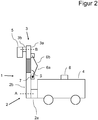
- the control device 8 is designed to control the hydraulic cylinder when a distance is predefined in such a way that the working height of the machine 5 and the predefined distance change. If, for example, an opposite of the representation in Figure 1 If a greater working height is specified, the control device controls 8 the hydraulic cylinder in such a way that the mast element 2b is extended. This is in Figure 2 shown.
- Figure 2 shows the view according to Figure 1 across from Figure 1 telescopic mast element 2b extended by means of the hydraulic cylinder. As can be clearly seen, the angle ⁇ between the first arm 6a and mast element 2b is smaller compared to the lower working height according to FIG Figure 1 .
- the control device 8 calculates the respective working height from the measurement signals of the angle detector and can thus compare the actual working height with the specified target working height in order to carry out a control such that the machine 5 is driven to the desired working height.
- the machine 5 represents a cutting device for rows of grapevines, which is only shown schematically as a block.
- such cutting devices have an elongated structure with several rotating knives arranged one above the other, which are hydraulically driven.
- hydraulic lines are fed from the hydraulic unit of the vehicle 4 via the mast element 2b to the end of the first arm 6a facing the mast element 2b, along the first arm to the second arm, along the second arm to the end of the second arm facing the main element 3a of the main element 3a to the pivot element 3b and finally to the machine 5.
- the holding device has further hydraulic cylinders to pivot the mast element 2b relative to the vehicle bracket 2a about an axis A and further hydraulic cylinders to pivot the pivot element 3b about an axis B relative to the main element 3a.
- the pivot axes between the first arm and the second arm, the first arm and the mast element and the second arm and the main element are parallel and are perpendicular to a direction of travel of the vehicle 4 when driving straight ahead.
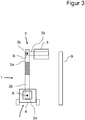
- Figures 1 and 2 are these axes of rotation thus perpendicular to the plane of the drawing
- Figures 3 and 4th these axes lie parallel to the plane of the drawing.
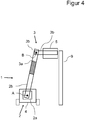
- first and second arm extends in a plane which is parallel to the direction of travel when driving straight ahead. Accordingly, the user's field of vision is only slightly restricted by the first arm 6a and the second arm 6b and the lines routed thereon, as in particular in FIG Figures 3 and 4th , which show a top view from the front, can be seen.
- the carrier device also has a mast angle detector which is arranged on the pivot axis A between the vehicle holder 2a and the mast element 2b. Furthermore, the device has a machine angle detector which is arranged on the pivot axis B between the pivot element 3B and the main element 3A. These detectors are also connected to the control device 8.
- the control device 8 pivots the mast element 2b relative to the vehicle bracket in the view according to FIG Figure 3 clockwise.
- the control device 8 pivots the pivot element 3b relative to the main element 3a counterclockwise, so that the rotational movement is compensated and the pivot element 3b remains in a horizontal position.
- This is possible by means of a regulation, since the respective angular positions can be determined by the control device 8 by means of the mast angle detector and machine angle detector.
- the pivoting movements are carried out by the aforementioned hydraulic cylinders under control of the control devices.
- the control device 8 is therefore additionally designed to compensate for a difference in height of the machine 5 when the mast element 2b is pivoted relative to the vehicle mount 2a and the pivoting element 3b is moved in a countermovement to the main element 3a, as described above, in that the mast element 2b is extended in the present case, ie a sliding movement of the main element 3a away from the vehicle mount 2a takes place.
- the distance of the displacement path is chosen so that in the end position according to Figure 4 the machine 5 is approached to the grapevine line 9, but at the same working height as in Figure 3 is located.
Landscapes
- Life Sciences & Earth Sciences (AREA)
- Environmental Sciences (AREA)
- Biodiversity & Conservation Biology (AREA)
- Ecology (AREA)
- Forests & Forestry (AREA)
- Engineering & Computer Science (AREA)
- Mechanical Engineering (AREA)
- Soil Sciences (AREA)
- Lifting Devices For Agricultural Implements (AREA)
- Agricultural Machines (AREA)
Claims (9)
- Dispositif de maintien (1) dévolu à une machine (5) de traitement de plantes, comprenant un élément de support (2) dédié à la fixation dudit dispositif de maintien (1) à un véhicule (4) et
un élément de retenue (3) pouvant être déplacé par rapport audit élément de support (2), en vue de positionner la machine (5) sur ledit élément de retenue (3),
caractérisé par le fait
que ledit dispositif de maintien (1) est muni d'un détecteur de courses affecté à la détection d'une course de déplacement de l'élément de retenue par rapport à l'élément de support (2), sachant que ledit détecteur de courses comporte au moins des premier et second bras (6a, 6b) et un capteur angulaire (7), que le premier bras (6a) est agencé sur ledit élément de support (2) avec faculté de pivotement au moins indirect, et que le second bras (6b) est agencé sur ledit premier bras avec faculté de pivotement au moins indirect, et sur ledit élément de retenue (3) avec faculté de pivotement au moins indirect ; et
que ledit capteur angulaire (7) est agencé de manière à détecter, au moins indirectement, une variation angulaire entre les deux bras (6a, 6b), entre le premier bras (6a) et l'élément de support (2), et/ou entre le second bras (6b) et l'élément de retenue (3). - Dispositif de maintien (1) selon la revendication 1,
caractérisé par le fait
qu'au moins un conducteur ou conduit, notamment un conducteur électrique et/ou un conduit hydraulique, est (sont) guidé(s) entre l'élément de support (2) et l'élément de retenue (3) au moins sur l'un des bras, de préférence sur les deux bras, le long des deux bras avec préférence particulière. - Dispositif de maintien (1) selon l'une des revendications précédentes,
caractérisé par le fait
que l'élément de retenue (3) est agencé sur l'élément de support (2) avec faculté de déplacement rectiligne. - Dispositif de maintien (1) selon l'une des revendications précédentes,
caractérisé par le fait
que le premier bras est implanté sur l'élément de support (2), de même que le second bras est implanté sur ledit premier bras et sur l'élément de retenue (3), à chaque fois sans interposition d'éléments pivotants supplémentaires. - Dispositif de maintien (1) selon l'une des revendications précédentes,
caractérisé par le fait
que le capteur angulaire (7) est interposé entre l'élément de support (2) et le premier bras, afin de mesurer une variation angulaire entre ledit premier bras et ledit élément de support (2). - Dispositif de maintien (1) selon l'une des revendications précédentes,
caractérisé par le fait
que le capteur angulaire est conçu et disposé de façon telle qu'il existe une relation linéaire entre la localisation de l'élément de retenue, le long de la course de déplacement, et la position angulaire dudit capteur angulaire. - Dispositif de maintien (1) selon l'une des revendications précédentes,
caractérisé par le fait
que la course de déplacement mesure au moins 50 cm, de préférence au moins 70 cm ; et/ou par le fait que ladite course de déplacement se situe dans la plage de 30 cm à 200 cm, préférentiellement de 40 cm à 150 cm. - Dispositif de maintien (1) selon l'une des revendications précédentes,
caractérisé par le fait
que l'élément de support (2) comprend un support de montage (2a) dédié à l'implantation sur le véhicule (4), et un élément (2b) formant mât et agencé à pivotement sur ledit support (2a) de montage sur ledit véhicule, l'élément de retenue (3) étant agencé avec faculté de déplacement sur ledit élément (2b) formant mât ; et par le fait que ledit élément de support (2) est doté d'un capteur d'angles de mât, conçu pour détecter un angle de pivotement entre ledit support (2a) de montage sur le véhicule, et ledit élément (2b) formant mât. - Procédé de commande d'un dispositif de maintien (1) dévolu à une machine (5) de traitement de plantes, comprenant un élément de support (2) dédié à la fixation dudit dispositif de maintien (1) à un véhicule (4), et un élément de retenue (3) pouvant être déplacé par rapport audit élément de support (2), en vue de positionner la machine (5) sur ledit élément de retenue (3),
caractérisé par le fait
que le dispositif de maintien (1) est commandé en fonction de signaux de mesure d'un détecteur de courses, sachant que ledit détecteur de courses comporte au moins des premier et second bras (6a, 6b) et un capteur angulaire (7), que le premier bras (6a) est agencé sur ledit élément de support (2) avec faculté de pivotement au moins indirect, et que le second bras (6b) est agencé sur ledit premier bras (6a) avec faculté de pivotement au moins indirect, et sur ledit élément de retenue (3) avec faculté de pivotement au moins indirect ; et
qu'au moins une variation angulaire entre les deux bras (6a, 6b), entre le premier bras (6a) et l'élément de retenue (3), et/ou entre le second bras (6b) et ledit élément de retenue (3), est détectée au moins indirectement au moyen dudit capteur angulaire (7).
Applications Claiming Priority (1)
| Application Number | Priority Date | Filing Date | Title |
|---|---|---|---|
| DE102018112365.5A DE102018112365B3 (de) | 2018-05-23 | 2018-05-23 | Haltevorrichtung für eine Maschine zur Pflanzenbearbeitung und Verfahren zum Steuern solch einer Haltevorrichtung |
Publications (2)
| Publication Number | Publication Date |
|---|---|
| EP3571909A1 EP3571909A1 (fr) | 2019-11-27 |
| EP3571909B1 true EP3571909B1 (fr) | 2021-01-27 |
Family
ID=66589294
Family Applications (1)
| Application Number | Title | Priority Date | Filing Date |
|---|---|---|---|
| EP19174841.7A Active EP3571909B1 (fr) | 2018-05-23 | 2019-05-16 | Dispositif de maintien pour une machine de traitement de plantes et procédé de commande d'un tel dispositif de maintien |
Country Status (2)
| Country | Link |
|---|---|
| EP (1) | EP3571909B1 (fr) |
| DE (1) | DE102018112365B3 (fr) |
Family Cites Families (7)
| Publication number | Priority date | Publication date | Assignee | Title |
|---|---|---|---|---|
| GB2249011B (en) | 1990-10-27 | 1994-02-16 | Bomford Turner Ltd | Improvements in mowers. |
| EP0898877B1 (fr) * | 1997-08-21 | 2003-04-02 | Industrie et Nature de Navarre (I2N), Société Anonyme | Dispositif pour l'effeuillage des vignes |
| PT951813E (pt) | 1998-04-24 | 2004-04-30 | Binger France Sarl | Dispositivo de suporte de uma maquina utilizavel em especial na agricultura na arboricultura e na viticultura |
| DE102007020801A1 (de) | 2007-05-03 | 2008-11-06 | Herder B.V. | In der Höhe einstellbare Landbearbeitungseinrichtung |
| DE102010007276A1 (de) * | 2010-02-08 | 2011-08-11 | ERO-Gerätebau GmbH, 55469 | Steuervorrichtung und Verfahren zur Steuerung einer an einem Fahrzeug anordbaren Haltevorrichtung für eine Maschine zur Pflanzenbearbeitung |
| JP6068429B2 (ja) | 2014-12-25 | 2017-01-25 | ファナック株式会社 | ロボット識別システム |
| DE102016115934B4 (de) | 2016-08-26 | 2020-12-03 | ERO - Gerätebau GmbH | Haltevorrichtung für eine Maschine zur Pflanzenbearbeitung und Verfahren zum Betreiben einer Haltevorrichtung für eine Maschine zur Pflanzenbearbeitung |
-
2018
- 2018-05-23 DE DE102018112365.5A patent/DE102018112365B3/de not_active Expired - Fee Related
-
2019
- 2019-05-16 EP EP19174841.7A patent/EP3571909B1/fr active Active
Non-Patent Citations (1)
| Title |
|---|
| None * |
Also Published As
| Publication number | Publication date |
|---|---|
| DE102018112365B3 (de) | 2019-10-10 |
| EP3571909A1 (fr) | 2019-11-27 |
Similar Documents
| Publication | Publication Date | Title |
|---|---|---|
| EP3335532B1 (fr) | Herse à dents | |
| DE3604519C2 (fr) | ||
| DE2001542C3 (de) | Fahrbare Einrichtung zur Überwachung und/oder Korrektur der Lage eines Gleises | |
| DE1807653A1 (de) | Oberflaechenbearbeitungsmaschine mit Niveau- und Neigungsregelung | |
| EP0215142A1 (fr) | Diviseur d'épis pour machines agricoles | |
| DE102014113448A1 (de) | Zugfahrzeug und Anhängevorrichtung für ein Anbaugerät | |
| EP1407653A2 (fr) | Dispositif pour l'ajustement de la position d'un outil de travail par rapport à un véhicule porteur | |
| EP3772265A1 (fr) | Dispositif de houe | |
| DE102019125553A1 (de) | Bewegliche bedienerstation für verbesserte sicht | |
| DE2265142C3 (de) | Vorrichtung zum Steuern der Lenkung eines Fahrzeugs | |
| DE2815228B2 (fr) | ||
| EP3417685B1 (fr) | Procédé de détermination d'une grandeur physique d'un bras supérieur | |
| EP2950040B1 (fr) | Procédé d'assistance du conducteur d'un ensemble attelé de véhicule utilitaire et véhicule utilitaire avec un système d'assistance | |
| EP3571909B1 (fr) | Dispositif de maintien pour une machine de traitement de plantes et procédé de commande d'un tel dispositif de maintien | |
| EP4052550B1 (fr) | Dispositif de compensation de la suspension latérale pour la viticulture | |
| DE69107751T2 (de) | Elektronische Vorrichtung zum Steuern der Arbeitstiefe und des Hebens eines Aufsatteldrehpfluges. | |
| EP3243372A1 (fr) | Procédé de réglage d'un angle de coupe d'un outil avant disposé sur une moissonneuse automobile | |
| EP3735810B1 (fr) | Dispositif d'accouplement pour un attelage | |
| EP0012997B1 (fr) | Charrue réversible | |
| EP2394501B1 (fr) | Dispositif de commande et procédé de commande d'un dispositif de retenue pouvant être agencé sur un véhicule pour une machine destinée à la préparation de plantes | |
| EP4275463A1 (fr) | Outil de travail agricole | |
| DE102018107406A1 (de) | Erntevorsatzgerät | |
| DE2703221C2 (de) | Bodenbearbeitungsgerät | |
| DE102022111876A1 (de) | Bearbeitungssystem, insbesondere für den Einsatz im Wein- und Obstbau | |
| DE102024112871A1 (de) | Verfahren zum Betreiben eines an einer Aufnahmevorrichtung eines Mähdreschers angeordneten Vorsatzgerätes sowie selbstfahrender Mähdrescher |
Legal Events
| Date | Code | Title | Description |
|---|---|---|---|
| PUAI | Public reference made under article 153(3) epc to a published international application that has entered the european phase |
Free format text: ORIGINAL CODE: 0009012 |
|
| STAA | Information on the status of an ep patent application or granted ep patent |
Free format text: STATUS: THE APPLICATION HAS BEEN PUBLISHED |
|
| AK | Designated contracting states |
Kind code of ref document: A1 Designated state(s): AL AT BE BG CH CY CZ DE DK EE ES FI FR GB GR HR HU IE IS IT LI LT LU LV MC MK MT NL NO PL PT RO RS SE SI SK SM TR |
|
| AX | Request for extension of the european patent |
Extension state: BA ME |
|
| STAA | Information on the status of an ep patent application or granted ep patent |
Free format text: STATUS: REQUEST FOR EXAMINATION WAS MADE |
|
| 17P | Request for examination filed |
Effective date: 20191209 |
|
| RBV | Designated contracting states (corrected) |
Designated state(s): AL AT BE BG CH CY CZ DE DK EE ES FI FR GB GR HR HU IE IS IT LI LT LU LV MC MK MT NL NO PL PT RO RS SE SI SK SM TR |
|
| GRAP | Despatch of communication of intention to grant a patent |
Free format text: ORIGINAL CODE: EPIDOSNIGR1 |
|
| STAA | Information on the status of an ep patent application or granted ep patent |
Free format text: STATUS: GRANT OF PATENT IS INTENDED |
|
| INTG | Intention to grant announced |
Effective date: 20201005 |
|
| GRAS | Grant fee paid |
Free format text: ORIGINAL CODE: EPIDOSNIGR3 |
|
| GRAA | (expected) grant |
Free format text: ORIGINAL CODE: 0009210 |
|
| STAA | Information on the status of an ep patent application or granted ep patent |
Free format text: STATUS: THE PATENT HAS BEEN GRANTED |
|
| AK | Designated contracting states |
Kind code of ref document: B1 Designated state(s): AL AT BE BG CH CY CZ DE DK EE ES FI FR GB GR HR HU IE IS IT LI LT LU LV MC MK MT NL NO PL PT RO RS SE SI SK SM TR |
|
| REG | Reference to a national code |
Ref country code: GB Ref legal event code: FG4D Free format text: NOT ENGLISH |
|
| REG | Reference to a national code |
Ref country code: CH Ref legal event code: EP |
|
| REG | Reference to a national code |
Ref country code: AT Ref legal event code: REF Ref document number: 1357489 Country of ref document: AT Kind code of ref document: T Effective date: 20210215 |
|
| REG | Reference to a national code |
Ref country code: IE Ref legal event code: FG4D Free format text: LANGUAGE OF EP DOCUMENT: GERMAN |
|
| REG | Reference to a national code |
Ref country code: DE Ref legal event code: R096 Ref document number: 502019000761 Country of ref document: DE |
|
| REG | Reference to a national code |
Ref country code: NL Ref legal event code: MP Effective date: 20210127 |
|
| REG | Reference to a national code |
Ref country code: LT Ref legal event code: MG9D |
|
| PG25 | Lapsed in a contracting state [announced via postgrant information from national office to epo] |
Ref country code: PT Free format text: LAPSE BECAUSE OF FAILURE TO SUBMIT A TRANSLATION OF THE DESCRIPTION OR TO PAY THE FEE WITHIN THE PRESCRIBED TIME-LIMIT Effective date: 20210527 Ref country code: NO Free format text: LAPSE BECAUSE OF FAILURE TO SUBMIT A TRANSLATION OF THE DESCRIPTION OR TO PAY THE FEE WITHIN THE PRESCRIBED TIME-LIMIT Effective date: 20210427 Ref country code: LT Free format text: LAPSE BECAUSE OF FAILURE TO SUBMIT A TRANSLATION OF THE DESCRIPTION OR TO PAY THE FEE WITHIN THE PRESCRIBED TIME-LIMIT Effective date: 20210127 Ref country code: BG Free format text: LAPSE BECAUSE OF FAILURE TO SUBMIT A TRANSLATION OF THE DESCRIPTION OR TO PAY THE FEE WITHIN THE PRESCRIBED TIME-LIMIT Effective date: 20210427 Ref country code: FI Free format text: LAPSE BECAUSE OF FAILURE TO SUBMIT A TRANSLATION OF THE DESCRIPTION OR TO PAY THE FEE WITHIN THE PRESCRIBED TIME-LIMIT Effective date: 20210127 Ref country code: HR Free format text: LAPSE BECAUSE OF FAILURE TO SUBMIT A TRANSLATION OF THE DESCRIPTION OR TO PAY THE FEE WITHIN THE PRESCRIBED TIME-LIMIT Effective date: 20210127 Ref country code: GR Free format text: LAPSE BECAUSE OF FAILURE TO SUBMIT A TRANSLATION OF THE DESCRIPTION OR TO PAY THE FEE WITHIN THE PRESCRIBED TIME-LIMIT Effective date: 20210428 |
|
| PG25 | Lapsed in a contracting state [announced via postgrant information from national office to epo] |
Ref country code: PL Free format text: LAPSE BECAUSE OF FAILURE TO SUBMIT A TRANSLATION OF THE DESCRIPTION OR TO PAY THE FEE WITHIN THE PRESCRIBED TIME-LIMIT Effective date: 20210127 Ref country code: LV Free format text: LAPSE BECAUSE OF FAILURE TO SUBMIT A TRANSLATION OF THE DESCRIPTION OR TO PAY THE FEE WITHIN THE PRESCRIBED TIME-LIMIT Effective date: 20210127 Ref country code: RS Free format text: LAPSE BECAUSE OF FAILURE TO SUBMIT A TRANSLATION OF THE DESCRIPTION OR TO PAY THE FEE WITHIN THE PRESCRIBED TIME-LIMIT Effective date: 20210127 Ref country code: SE Free format text: LAPSE BECAUSE OF FAILURE TO SUBMIT A TRANSLATION OF THE DESCRIPTION OR TO PAY THE FEE WITHIN THE PRESCRIBED TIME-LIMIT Effective date: 20210127 |
|
| PG25 | Lapsed in a contracting state [announced via postgrant information from national office to epo] |
Ref country code: IS Free format text: LAPSE BECAUSE OF FAILURE TO SUBMIT A TRANSLATION OF THE DESCRIPTION OR TO PAY THE FEE WITHIN THE PRESCRIBED TIME-LIMIT Effective date: 20210527 |
|
| REG | Reference to a national code |
Ref country code: DE Ref legal event code: R097 Ref document number: 502019000761 Country of ref document: DE |
|
| PG25 | Lapsed in a contracting state [announced via postgrant information from national office to epo] |
Ref country code: EE Free format text: LAPSE BECAUSE OF FAILURE TO SUBMIT A TRANSLATION OF THE DESCRIPTION OR TO PAY THE FEE WITHIN THE PRESCRIBED TIME-LIMIT Effective date: 20210127 Ref country code: CZ Free format text: LAPSE BECAUSE OF FAILURE TO SUBMIT A TRANSLATION OF THE DESCRIPTION OR TO PAY THE FEE WITHIN THE PRESCRIBED TIME-LIMIT Effective date: 20210127 Ref country code: SM Free format text: LAPSE BECAUSE OF FAILURE TO SUBMIT A TRANSLATION OF THE DESCRIPTION OR TO PAY THE FEE WITHIN THE PRESCRIBED TIME-LIMIT Effective date: 20210127 |
|
| PG25 | Lapsed in a contracting state [announced via postgrant information from national office to epo] |
Ref country code: DK Free format text: LAPSE BECAUSE OF FAILURE TO SUBMIT A TRANSLATION OF THE DESCRIPTION OR TO PAY THE FEE WITHIN THE PRESCRIBED TIME-LIMIT Effective date: 20210127 Ref country code: SK Free format text: LAPSE BECAUSE OF FAILURE TO SUBMIT A TRANSLATION OF THE DESCRIPTION OR TO PAY THE FEE WITHIN THE PRESCRIBED TIME-LIMIT Effective date: 20210127 Ref country code: RO Free format text: LAPSE BECAUSE OF FAILURE TO SUBMIT A TRANSLATION OF THE DESCRIPTION OR TO PAY THE FEE WITHIN THE PRESCRIBED TIME-LIMIT Effective date: 20210127 |
|
| PLBE | No opposition filed within time limit |
Free format text: ORIGINAL CODE: 0009261 |
|
| STAA | Information on the status of an ep patent application or granted ep patent |
Free format text: STATUS: NO OPPOSITION FILED WITHIN TIME LIMIT |
|
| 26N | No opposition filed |
Effective date: 20211028 |
|
| PG25 | Lapsed in a contracting state [announced via postgrant information from national office to epo] |
Ref country code: ES Free format text: LAPSE BECAUSE OF FAILURE TO SUBMIT A TRANSLATION OF THE DESCRIPTION OR TO PAY THE FEE WITHIN THE PRESCRIBED TIME-LIMIT Effective date: 20210127 Ref country code: MC Free format text: LAPSE BECAUSE OF FAILURE TO SUBMIT A TRANSLATION OF THE DESCRIPTION OR TO PAY THE FEE WITHIN THE PRESCRIBED TIME-LIMIT Effective date: 20210127 Ref country code: LU Free format text: LAPSE BECAUSE OF NON-PAYMENT OF DUE FEES Effective date: 20210516 Ref country code: AL Free format text: LAPSE BECAUSE OF FAILURE TO SUBMIT A TRANSLATION OF THE DESCRIPTION OR TO PAY THE FEE WITHIN THE PRESCRIBED TIME-LIMIT Effective date: 20210127 |
|
| REG | Reference to a national code |
Ref country code: BE Ref legal event code: MM Effective date: 20210531 |
|
| PG25 | Lapsed in a contracting state [announced via postgrant information from national office to epo] |
Ref country code: SI Free format text: LAPSE BECAUSE OF FAILURE TO SUBMIT A TRANSLATION OF THE DESCRIPTION OR TO PAY THE FEE WITHIN THE PRESCRIBED TIME-LIMIT Effective date: 20210127 |
|
| PG25 | Lapsed in a contracting state [announced via postgrant information from national office to epo] |
Ref country code: IE Free format text: LAPSE BECAUSE OF NON-PAYMENT OF DUE FEES Effective date: 20210516 |
|
| PG25 | Lapsed in a contracting state [announced via postgrant information from national office to epo] |
Ref country code: IS Free format text: LAPSE BECAUSE OF FAILURE TO SUBMIT A TRANSLATION OF THE DESCRIPTION OR TO PAY THE FEE WITHIN THE PRESCRIBED TIME-LIMIT Effective date: 20210527 |
|
| PG25 | Lapsed in a contracting state [announced via postgrant information from national office to epo] |
Ref country code: BE Free format text: LAPSE BECAUSE OF NON-PAYMENT OF DUE FEES Effective date: 20210531 |
|
| REG | Reference to a national code |
Ref country code: CH Ref legal event code: PL |
|
| PG25 | Lapsed in a contracting state [announced via postgrant information from national office to epo] |
Ref country code: LI Free format text: LAPSE BECAUSE OF NON-PAYMENT OF DUE FEES Effective date: 20220531 Ref country code: CH Free format text: LAPSE BECAUSE OF NON-PAYMENT OF DUE FEES Effective date: 20220531 |
|
| P01 | Opt-out of the competence of the unified patent court (upc) registered |
Effective date: 20230515 |
|
| PG25 | Lapsed in a contracting state [announced via postgrant information from national office to epo] |
Ref country code: NL Free format text: LAPSE BECAUSE OF NON-PAYMENT OF DUE FEES Effective date: 20210127 Ref country code: CY Free format text: LAPSE BECAUSE OF FAILURE TO SUBMIT A TRANSLATION OF THE DESCRIPTION OR TO PAY THE FEE WITHIN THE PRESCRIBED TIME-LIMIT Effective date: 20210127 |
|
| PG25 | Lapsed in a contracting state [announced via postgrant information from national office to epo] |
Ref country code: HU Free format text: LAPSE BECAUSE OF FAILURE TO SUBMIT A TRANSLATION OF THE DESCRIPTION OR TO PAY THE FEE WITHIN THE PRESCRIBED TIME-LIMIT; INVALID AB INITIO Effective date: 20190516 |
|
| GBPC | Gb: european patent ceased through non-payment of renewal fee |
Effective date: 20230516 |
|
| PG25 | Lapsed in a contracting state [announced via postgrant information from national office to epo] |
Ref country code: MK Free format text: LAPSE BECAUSE OF FAILURE TO SUBMIT A TRANSLATION OF THE DESCRIPTION OR TO PAY THE FEE WITHIN THE PRESCRIBED TIME-LIMIT Effective date: 20210127 Ref country code: GB Free format text: LAPSE BECAUSE OF NON-PAYMENT OF DUE FEES Effective date: 20230516 |
|
| PG25 | Lapsed in a contracting state [announced via postgrant information from national office to epo] |
Ref country code: TR Free format text: LAPSE BECAUSE OF FAILURE TO SUBMIT A TRANSLATION OF THE DESCRIPTION OR TO PAY THE FEE WITHIN THE PRESCRIBED TIME-LIMIT Effective date: 20210127 |
|
| PG25 | Lapsed in a contracting state [announced via postgrant information from national office to epo] |
Ref country code: MT Free format text: LAPSE BECAUSE OF FAILURE TO SUBMIT A TRANSLATION OF THE DESCRIPTION OR TO PAY THE FEE WITHIN THE PRESCRIBED TIME-LIMIT Effective date: 20210127 |
|
| PGFP | Annual fee paid to national office [announced via postgrant information from national office to epo] |
Ref country code: DE Payment date: 20250317 Year of fee payment: 7 |
|
| PGFP | Annual fee paid to national office [announced via postgrant information from national office to epo] |
Ref country code: IT Payment date: 20250530 Year of fee payment: 7 |
|
| PGFP | Annual fee paid to national office [announced via postgrant information from national office to epo] |
Ref country code: FR Payment date: 20250526 Year of fee payment: 7 |
|
| PGFP | Annual fee paid to national office [announced via postgrant information from national office to epo] |
Ref country code: AT Payment date: 20250519 Year of fee payment: 7 |