EP3571971A1 - Dispositif de guidage d'un aspirateur doté d'un sac d'aspirateur, procédé de positionnement d'un sac d'aspirateur et plaque de retenue - Google Patents
Dispositif de guidage d'un aspirateur doté d'un sac d'aspirateur, procédé de positionnement d'un sac d'aspirateur et plaque de retenue Download PDFInfo
- Publication number
- EP3571971A1 EP3571971A1 EP19166508.2A EP19166508A EP3571971A1 EP 3571971 A1 EP3571971 A1 EP 3571971A1 EP 19166508 A EP19166508 A EP 19166508A EP 3571971 A1 EP3571971 A1 EP 3571971A1
- Authority
- EP
- European Patent Office
- Prior art keywords
- vacuum cleaner
- base plate
- holding plate
- closure flap
- guide
- Prior art date
- Legal status (The legal status is an assumption and is not a legal conclusion. Google has not performed a legal analysis and makes no representation as to the accuracy of the status listed.)
- Granted
Links
Images


Classifications
-
- A—HUMAN NECESSITIES
- A47—FURNITURE; DOMESTIC ARTICLES OR APPLIANCES; COFFEE MILLS; SPICE MILLS; SUCTION CLEANERS IN GENERAL
- A47L—DOMESTIC WASHING OR CLEANING; SUCTION CLEANERS IN GENERAL
- A47L9/00—Details or accessories of suction cleaners, e.g. mechanical means for controlling the suction or for effecting pulsating action; Storing devices specially adapted to suction cleaners or parts thereof; Carrying-vehicles specially adapted for suction cleaners
- A47L9/10—Filters; Dust separators; Dust removal; Automatic exchange of filters
- A47L9/14—Bags or the like; Rigid filtering receptacles; Attachment of, or closures for, bags or receptacles
- A47L9/1427—Means for mounting or attaching bags or filtering receptacles in suction cleaners; Adapters
- A47L9/1436—Connecting plates, e.g. collars, end closures
- A47L9/1445—Connecting plates, e.g. collars, end closures with closure means
- A47L9/1454—Self-sealing closures, e.g. valves
Definitions
- the present invention relates to a guide device of a vacuum cleaner with a vacuum cleaner bag, wherein the vacuum cleaner bag is fixed to a support plate having a base plate on which an inflow opening is formed, wherein on the base plate a closure flap is pivotally mounted, by means of which the inflow opening is closable, a holding plate for a vacuum cleaner bag and a method for positioning a vacuum cleaner bag with a holding plate in a vacuum cleaner.
- the DE 102 03 460 A1 discloses a vacuum cleaner bag with a holding plate, which is inserted into a guide device of a vacuum cleaner. On the holding plate, a displaceable closure element is provided, by means of which an inflow opening can be covered on the holding plate.
- the vacuum cleaner bag is fixed by the holding plate on the guide device of the vacuum cleaner by inserting.
- the retaining plate is comparatively long and is held with play in the leadership of the vacuum cleaner. As a result, the positioning of the holding plate is not very accurate and the holding plate requires a comparatively large amount of space.
- the DE 10 2007 053 151 A1 discloses a retaining plate for a vacuum cleaner bag, wherein in the holding plate, an inflow opening is formed, which is closable via an integrally formed pivotable flap.
- the flap can be inserted in a trough-shaped receptacle of the holding plate.
- At least one projecting guide element which can be inserted into a guide device of a vacuum cleaner, is formed on the holding flap on a holding plate which has a base plate and a pivotable closing flap.
- the closure flap can be pivoted relative to the base plate, which, in the installation situation, makes possible an angular alignment of the closure flap relative to the base plate.
- the required installation volume for the retaining plate is reduced because the closure flap adapts better to the contour of the adjacently arranged vacuum cleaner bag.
- the handling of the flap is improved because it is pivoted after manufacture at least twice by inserting and pulling out of the guide device, so that it can then be easily operated by the user.
- the guide device has a straight and a curved guide portion.
- the guide element on the closure flap is preferably inserted in the mounted position in the bent guide portion, so that the closure flap is pivoted during insertion relative to the base plate.
- the base plate is inserted only in the straight guide section, so that a smooth shifting is possible.
- the guide element may be formed as a web which extends substantially parallel to a rotational axis of the closure flap.
- the guide element can protrude on one side or on both sides of the closure flap, for a material-saving construction, the guide element can preferably be provided only on one side of the closure flap.
- the base plate in the insertion direction has a small length, in particular a length which is smaller than 1.5 times the diameter of the inflow opening.
- the length of the base plate in the insertion direction may be between 0.9 times to 1.2 times the diameter of the inflow opening in the base plate.
- the bendable web can be designed as a bridge web, which is connected at opposite ends to the base plate.
- a slot-shaped opening can be formed between the bendable web and the base plate, which gives the bendable web a freedom of movement perpendicular to the direction of insertion, which, for example, can be between 1 mm and 3 mm.
- the vacuum cleaner bag with the holding plate is first inserted into a guide device of the vacuum cleaner, wherein a closing flap pivotably mounted on a base plate is arranged in the front insertion direction.
- the closure flap is simultaneously pivoted about an axis of rotation relative to the base plate, wherein the closure flap is guided with a guide element in the guide device.
- the guide device preferably has a straight guide section and a curved guide section.
- the base plate is inserted only in the straight guide portion, while the guide member is pushed on the closure flap first by the straight guide portion and then in the bent guide portion to effect pivoting relative to the base plate.
- the vacuum cleaner preferably has a detection device, by means of which it is possible to detect whether a vacuum cleaner bag with a retaining plate has been inserted into the guiding device, wherein the closing flap switches the detecting device on insertion.
- the closure flap can optionally be locked in the inserted position on the guide device.
- a holding plate 1 for a vacuum cleaner bag comprises a base plate 2, which has a substantially rectangular outer contour.
- an inflow opening 3 is formed, into which a nozzle of a vacuum cleaner can be inserted.
- an elastic sealing element, or the filter material of the vacuum cleaner bag projects annularly into the inflow opening 3 and thus forms the opening into which the neck of the vacuum cleaner is inserted positively or non-positively.
- the inflow opening 3 of the base plate 2 can thus be made larger than an inflow opening in the filter material of the vacuum cleaner bag or an annular sealing element on the inflow opening third
- a closure flap 4 is articulated, which is integrally formed with the base plate and is connected via two spaced film hinges 5 to the base plate 2.
- the flap 4 can from the in the Figures 1A and 1B shown opening position to be pivoted by about 180 ° in a closed position to substantially cover the inflow opening 3 and thereby to close.
- the closure flap 4 covers at least the opening area within a sealing ring or the opening in the filter material in the closed position.
- an arcuate region 7 is formed on the closure flap 4, which surrounds a ring 6 around the inflow opening 3.
- the axis of rotation of the closure flap 4 in the region of the ring 6 can be arranged around the inflow opening 3.
- the filter material of a vacuum cleaner bag can be fixed, for example by welding or gluing.
- the vacuum cleaner bag may be formed as a flat bag or block bottom bag, in particular of a single or multi-layer nonwoven fabric or another filter material.
- a laterally projecting guide element 8 is formed, which protrudes in the manner of a web parallel to the axis of rotation of the closure flap 4 and can engage in a guide device of a vacuum cleaner.
- a latching web 9 On the guide element 8 is a latching web 9, which can be latched to a locking receptacle 10 of the base plate 2.
- the locking receptacle 10 may be formed as a recess or receptacle and have a holding element on which the guide element 8 can be latched.
- the closure flap 4 has, on the side opposite the film hinges 5, a point 11 with a step-shaped formation which can be placed in a closed position in a form-locking manner against the edge around the inflow opening 3.
- a narrow web-shaped arm 12 is further formed, which is parallel to the plane of the base plate and the flap 4 in the Figures 1A and 1B extends and has almost the same length as the flap 4.
- the boom 12 forms a stop for limiting the insertion depth.
- the base plate 2 without the boom 12 is short in the insertion direction, for example, with a length between 1 and 1.2 times the diameter of the inflow opening third
- a bendable web 14 is formed, which is connected at opposite ends to the base plate 2.
- the bendable web 14 is thus designed bridge-shaped and spaced from a slot-shaped opening 15 in a central region of the base plate 2.
- the slot-shaped opening 15 allows a bending movement of the web 14, which may be for example between 1 mm and 3 mm perpendicular to the insertion direction.
- the bendable web 14 extends in this case by at least 50% of the length of the base plate 2 in the insertion direction, preferably between 60% and 90% of the length.
- the base plate 2 On the opposite side to the flap 4, the base plate 2 has a protruding handle portion 13, on which the base plate 2 can be gripped during insertion and withdrawal from a guide device.
- the handle portion 13 protrudes beyond an edge of the base plate 2 and can be disregarded due to the narrow configuration in the determination of the length of the base plate 2 in the insertion direction.
- ribs 16 are further provided on a side facing the vacuum cleaner bag side, which are inserted into elongated receptacles 17 of an adjacent base plate 2, so that the holding plate 1 is better stackable in the packaging of the vacuum cleaner bag.
- the elongate receptacles 17 serve for the form-fitting reception of the ribs 16 on the opposite side of the base plate 2.
- FIG. 2 the holding plate 1 is shown in a guide device 30 of a vacuum cleaner without the other components of the vacuum cleaner and the filter bag of the vacuum cleaner bag.
- the guide device 30 comprises on opposite sides a groove or a channel with a straight guide portion 31 and an adjoining curved or angled guide portion 33.
- the base plate 2 is positioned, wherein on a groove wall to the base plate 2 projecting web 32nd is formed, which tapers the groove and the base plate 2 holds substantially form-fitting in an operating position.
- the straight guide section 31 is adjoined by the curved guide section 33, which protrudes at an angle from the plane of the base plate 2 and opens into a pocket 34.
- the bent or angled guide portion 33 is aligned, for example, at an angle between 20 ° to 80 °, in particular 30 ° to 70 °, to the plane of the base plate 2.
- the flap 4 When inserting the holding plate 1, the flap 4 is arranged at the front.
- the closure flap 4 When inserting the holding plate 1 into the guide device 30, the closure flap 4 initially remains in the plane of the base plate 2 until the laterally projecting guide element on the closure flap 4 reaches the curved guide section 33. Then, via the guide member 8, which slides in the curved guide portion 33, a pivoting of the closure flap 4 is effected about the film hinges 5, until the holding plate 1 is arranged in an end position.
- the end position can be specified for example via the boom 12, which represents a stop which cooperates with a counter-stop on the vacuum cleaner.
- any stop to limit the insertion depth may also be provided at a different position.
- the closure flap 4 is pivoted by insertion into the guide device 30, preferably at an angle of more than 10 °, preferably between 20 ° and 60 °. In the retracted position is the Space requirement of the holding plate 1 is reduced because the flap 4 is adapted to the geometry of the vacuum cleaner bag.
- the vacuum cleaner preferably has a detection device, by means of which it can be detected whether a vacuum cleaner bag has been inserted with a holding plate in the guide device.
- This detection device can for example be made mechanically and actuated by the boom 12 or the closure flap 4, so that the vacuum cleaner knows whether a vacuum cleaner bag has been inserted or not, which can trigger, for example, a Einperrblockade or other measure on the vacuum cleaner.
- the holding plate 1 When the vacuum cleaner bag is filled, the holding plate 1 can be pulled out by pulling on the handle portion 13, wherein the shutter 4 is aligned by the guide on the curved guide portion 33 again parallel to the base plate 2 and then manually can be folded by the user in the closed position ,
- the pivotability of the flap 4 is smooth, since the film hinges 5 have been moved before.
- closure flap 4 is pivotally mounted on the base plate 2 via two film hinges 5.
- two film hinges 5 it is also possible to prefer only one single film hinge 5 or more than two film hinges 5.
- closure flap 4 does not have to be integrally formed with the base plate 2, but can be manufactured separately from the base plate 2. Then, the base plate 2 can be connected to the shutter 4 via a hinge.
- the closure flap 4 can also be biased by a spring in the closing direction, so that when the holding plate 1 is pulled out of the guiding device 30, the closing flap 4 is already moved in the closing direction by the force of the spring, preferably even as far as the closing position.
- the fixed to the base plate 2 vacuum cleaner bag can be made as a flat bag, block bottom bag or other bag made of a filter material.
- the filter bag is welded to the base plate 2 and the filter material of a single or multi-ply nonwoven fabric.
- Other filter materials can be used for the vacuum cleaner bag.
- the holding plate 1 can be made as a one-piece component made of plastic.
- a bendable bridge-shaped web 14 is formed on each side.
- the webs may also have a different shape and be connected only on one side with the base plate 2.
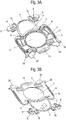
- FIGS. 3A and 3B a modified retaining plate for a vacuum cleaner bag is shown, which has a base plate 2 with an inflow opening 3, which is closable via a hinged and integrally formed closure flap 4.
- the closure flap 4 is connected to the base plate 2 via two spaced-apart film hinges 5 and has two laterally projecting guide elements 8.
- the two web-shaped guide elements 8 protrude from the closure flap 4 parallel to its axis of rotation and can in the in FIG. 2 illustrated guide device of a vacuum cleaner.
- a latching web 9 is provided, which can optionally be latched to a locking receptacle 10 of the base plate 2.
- engaging elements 18 are additionally provided in the region of the guide elements 8, which ensure a correct positioning of the holding plate in a guide device 30 of a vacuum cleaner.
- the engagement elements 18 are bow-shaped, but may also have a different shape.
- lateral projections 19 and web-shaped tabs 20 are formed on the base plate 2, which also serve for the exact positioning of the holding plate in a guide device 30 of a vacuum cleaner.
- a slot-shaped opening and a flexible web 14 are formed on opposite sides, respectively, in order to improve the lateral guidance, as with reference to FIG FIG. 2 already explained.
- the vacuum cleaner bag can be pulled in this embodiment after the filling of the handle portion 13, then manually fold the flap 4 in the closed position.
Landscapes
- Engineering & Computer Science (AREA)
- Mechanical Engineering (AREA)
- Filters For Electric Vacuum Cleaners (AREA)
Applications Claiming Priority (2)
| Application Number | Priority Date | Filing Date | Title |
|---|---|---|---|
| DE102018112433 | 2018-05-24 | ||
| DE102019103676.3A DE102019103676A1 (de) | 2018-05-24 | 2019-02-13 | Führungsvorrichtung eines Staubsaugers mit einem Staubsaugerbeutel, Verfahren zum Positionieren eines Staubsaugerbeutels und Halteplatte |
Publications (2)
| Publication Number | Publication Date |
|---|---|
| EP3571971A1 true EP3571971A1 (fr) | 2019-11-27 |
| EP3571971B1 EP3571971B1 (fr) | 2023-06-07 |
Family
ID=66049048
Family Applications (1)
| Application Number | Title | Priority Date | Filing Date |
|---|---|---|---|
| EP19166508.2A Active EP3571971B1 (fr) | 2018-05-24 | 2019-04-01 | Dispositif de guidage d'un aspirateur doté d'un sac d'aspirateur, procédé de positionnement d'un sac d'aspirateur et plaque de retenue |
Country Status (2)
| Country | Link |
|---|---|
| EP (1) | EP3571971B1 (fr) |
| PL (1) | PL3571971T3 (fr) |
Cited By (2)
| Publication number | Priority date | Publication date | Assignee | Title |
|---|---|---|---|---|
| US11718275B2 (en) * | 2018-08-27 | 2023-08-08 | Shop Vac Corporation | Grill and flapper valve for a vacuum cleaner assembly |
| USD1041108S1 (en) * | 2021-07-15 | 2024-09-03 | Alfred Kaercher Se & Co. Kg | Docking station for a floor cleaning machine |
Citations (5)
| Publication number | Priority date | Publication date | Assignee | Title |
|---|---|---|---|---|
| DE19644897A1 (de) * | 1996-10-29 | 1998-04-30 | Vorwerk Co Interholding | Staubsauger mit einer Kammer zur Aufnahme eines Staubfilterbeutels |
| DE19711611A1 (de) * | 1997-03-20 | 1998-09-24 | Aichner Filter Gmbh | Halteplatte eines Staubsauger-Filterbeutels |
| DE10203460A1 (de) | 2001-01-27 | 2002-08-29 | Wolf Gmbh | In einen Staubsauger einsetzbare Filtereinrichtung |
| DE102007053151A1 (de) | 2007-11-08 | 2009-05-14 | Wolf Pvg Gmbh & Co. Kg | Halteplatte für einen Staubsaugerbeutel und Verfahren zu deren Herstellung |
| EP2732747A2 (fr) * | 2012-11-19 | 2014-05-21 | Vorwerk & Co. Interholding GmbH | Sac filtrant d'aspirateur, avec fermeture de ressort |
-
2019
- 2019-04-01 EP EP19166508.2A patent/EP3571971B1/fr active Active
- 2019-04-01 PL PL19166508.2T patent/PL3571971T3/pl unknown
Patent Citations (5)
| Publication number | Priority date | Publication date | Assignee | Title |
|---|---|---|---|---|
| DE19644897A1 (de) * | 1996-10-29 | 1998-04-30 | Vorwerk Co Interholding | Staubsauger mit einer Kammer zur Aufnahme eines Staubfilterbeutels |
| DE19711611A1 (de) * | 1997-03-20 | 1998-09-24 | Aichner Filter Gmbh | Halteplatte eines Staubsauger-Filterbeutels |
| DE10203460A1 (de) | 2001-01-27 | 2002-08-29 | Wolf Gmbh | In einen Staubsauger einsetzbare Filtereinrichtung |
| DE102007053151A1 (de) | 2007-11-08 | 2009-05-14 | Wolf Pvg Gmbh & Co. Kg | Halteplatte für einen Staubsaugerbeutel und Verfahren zu deren Herstellung |
| EP2732747A2 (fr) * | 2012-11-19 | 2014-05-21 | Vorwerk & Co. Interholding GmbH | Sac filtrant d'aspirateur, avec fermeture de ressort |
Cited By (2)
| Publication number | Priority date | Publication date | Assignee | Title |
|---|---|---|---|---|
| US11718275B2 (en) * | 2018-08-27 | 2023-08-08 | Shop Vac Corporation | Grill and flapper valve for a vacuum cleaner assembly |
| USD1041108S1 (en) * | 2021-07-15 | 2024-09-03 | Alfred Kaercher Se & Co. Kg | Docking station for a floor cleaning machine |
Also Published As
| Publication number | Publication date |
|---|---|
| PL3571971T3 (pl) | 2023-10-16 |
| EP3571971B1 (fr) | 2023-06-07 |
Similar Documents
| Publication | Publication Date | Title |
|---|---|---|
| DE102008037409B4 (de) | Staubfilterbeutel-Aufnahmekammer für einen Staubsauger und Staubfilterbeutel zur Anordnung in der Staubfilterbeutel-Aufnahmekammer | |
| DE10142509B4 (de) | Staubsauger | |
| DE202008006904U1 (de) | Halteplatte für einen Staubsaugerbeutel | |
| DE102015110773A1 (de) | Behälterverschlussvorrichtung und Behälter | |
| EP3571971B1 (fr) | Dispositif de guidage d'un aspirateur doté d'un sac d'aspirateur, procédé de positionnement d'un sac d'aspirateur et plaque de retenue | |
| DE602004000781T2 (de) | Durch zweimaliges Drücken betätigte Schliessvorrichtung | |
| DE60119971T2 (de) | Spenderverschluss für einen behälter | |
| DE20005448U1 (de) | Halteplatte eines Staubsauger-Filterbeutels | |
| EP3571972B1 (fr) | Plaque de maintien pour un sac d'aspirateur et dispositif de guidage pour un aspirateur doté d'un sac d'aspirateur | |
| DE102019103676A1 (de) | Führungsvorrichtung eines Staubsaugers mit einem Staubsaugerbeutel, Verfahren zum Positionieren eines Staubsaugerbeutels und Halteplatte | |
| DE10120846A1 (de) | Elektrischer Steckverbinder | |
| EP3691975B1 (fr) | Dispositif de fermeture pour un sachet | |
| DE19739377C2 (de) | Verschluß für Staubsaugerdeckel | |
| DE3300190C2 (fr) | ||
| EP1174073B1 (fr) | Aspirateur électrique avec chambre à filtration | |
| WO2022237926A1 (fr) | Dispositif d'acheminement d'agent de peinture, pistolet de pulvérisation et ensemble | |
| DE19922847A1 (de) | Verschluß für einen Ausschnitt an einem Fahrzeugteil, insbesondere an einer Stoßstange | |
| EP0893964B1 (fr) | Aspirateur pourvu d'un logement pour sac-filtre a poussiere | |
| DE9405637U1 (de) | Filter-Einsatz-Beutel, insbesondere für Staubsauger | |
| DE19906349C1 (de) | Mechanische Feststellvorrichtung für den Türflügel einer Tür | |
| DE9219082U1 (de) | Heftklammergerät | |
| DE4413313C2 (de) | Leuchte | |
| EP1431113B1 (fr) | Pièce profilée de fixation et renforcement d'une portion à recouvrement dans un produit plat | |
| EP0046478B1 (fr) | Dispositif d'immobilisation pour prélarts à oeuillets en tôle emmanchés par rivetage | |
| EP2041699A1 (fr) | Dispositif d'insertion de carte |
Legal Events
| Date | Code | Title | Description |
|---|---|---|---|
| PUAI | Public reference made under article 153(3) epc to a published international application that has entered the european phase |
Free format text: ORIGINAL CODE: 0009012 |
|
| STAA | Information on the status of an ep patent application or granted ep patent |
Free format text: STATUS: THE APPLICATION HAS BEEN PUBLISHED |
|
| AK | Designated contracting states |
Kind code of ref document: A1 Designated state(s): AL AT BE BG CH CY CZ DE DK EE ES FI FR GB GR HR HU IE IS IT LI LT LU LV MC MK MT NL NO PL PT RO RS SE SI SK SM TR |
|
| AX | Request for extension of the european patent |
Extension state: BA ME |
|
| STAA | Information on the status of an ep patent application or granted ep patent |
Free format text: STATUS: REQUEST FOR EXAMINATION WAS MADE |
|
| 17P | Request for examination filed |
Effective date: 20200429 |
|
| RBV | Designated contracting states (corrected) |
Designated state(s): AL AT BE BG CH CY CZ DE DK EE ES FI FR GB GR HR HU IE IS IT LI LT LU LV MC MK MT NL NO PL PT RO RS SE SI SK SM TR |
|
| GRAP | Despatch of communication of intention to grant a patent |
Free format text: ORIGINAL CODE: EPIDOSNIGR1 |
|
| STAA | Information on the status of an ep patent application or granted ep patent |
Free format text: STATUS: GRANT OF PATENT IS INTENDED |
|
| INTG | Intention to grant announced |
Effective date: 20230104 |
|
| RAP3 | Party data changed (applicant data changed or rights of an application transferred) |
Owner name: WOLF PVG GMBH & CO. KG |
|
| GRAS | Grant fee paid |
Free format text: ORIGINAL CODE: EPIDOSNIGR3 |
|
| GRAA | (expected) grant |
Free format text: ORIGINAL CODE: 0009210 |
|
| STAA | Information on the status of an ep patent application or granted ep patent |
Free format text: STATUS: THE PATENT HAS BEEN GRANTED |
|
| AK | Designated contracting states |
Kind code of ref document: B1 Designated state(s): AL AT BE BG CH CY CZ DE DK EE ES FI FR GB GR HR HU IE IS IT LI LT LU LV MC MK MT NL NO PL PT RO RS SE SI SK SM TR |
|
| REG | Reference to a national code |
Ref country code: GB Ref legal event code: FG4D Free format text: NOT ENGLISH |
|
| REG | Reference to a national code |
Ref country code: CH Ref legal event code: EP Ref country code: AT Ref legal event code: REF Ref document number: 1572245 Country of ref document: AT Kind code of ref document: T Effective date: 20230615 Ref country code: DE Ref legal event code: R096 Ref document number: 502019007857 Country of ref document: DE |
|
| REG | Reference to a national code |
Ref country code: LT Ref legal event code: MG9D |
|
| REG | Reference to a national code |
Ref country code: NL Ref legal event code: MP Effective date: 20230607 |
|
| PG25 | Lapsed in a contracting state [announced via postgrant information from national office to epo] |
Ref country code: SE Free format text: LAPSE BECAUSE OF FAILURE TO SUBMIT A TRANSLATION OF THE DESCRIPTION OR TO PAY THE FEE WITHIN THE PRESCRIBED TIME-LIMIT Effective date: 20230607 Ref country code: NO Free format text: LAPSE BECAUSE OF FAILURE TO SUBMIT A TRANSLATION OF THE DESCRIPTION OR TO PAY THE FEE WITHIN THE PRESCRIBED TIME-LIMIT Effective date: 20230907 Ref country code: ES Free format text: LAPSE BECAUSE OF FAILURE TO SUBMIT A TRANSLATION OF THE DESCRIPTION OR TO PAY THE FEE WITHIN THE PRESCRIBED TIME-LIMIT Effective date: 20230607 |
|
| PG25 | Lapsed in a contracting state [announced via postgrant information from national office to epo] |
Ref country code: RS Free format text: LAPSE BECAUSE OF FAILURE TO SUBMIT A TRANSLATION OF THE DESCRIPTION OR TO PAY THE FEE WITHIN THE PRESCRIBED TIME-LIMIT Effective date: 20230607 Ref country code: NL Free format text: LAPSE BECAUSE OF FAILURE TO SUBMIT A TRANSLATION OF THE DESCRIPTION OR TO PAY THE FEE WITHIN THE PRESCRIBED TIME-LIMIT Effective date: 20230607 Ref country code: LV Free format text: LAPSE BECAUSE OF FAILURE TO SUBMIT A TRANSLATION OF THE DESCRIPTION OR TO PAY THE FEE WITHIN THE PRESCRIBED TIME-LIMIT Effective date: 20230607 Ref country code: LT Free format text: LAPSE BECAUSE OF FAILURE TO SUBMIT A TRANSLATION OF THE DESCRIPTION OR TO PAY THE FEE WITHIN THE PRESCRIBED TIME-LIMIT Effective date: 20230607 Ref country code: HR Free format text: LAPSE BECAUSE OF FAILURE TO SUBMIT A TRANSLATION OF THE DESCRIPTION OR TO PAY THE FEE WITHIN THE PRESCRIBED TIME-LIMIT Effective date: 20230607 Ref country code: GR Free format text: LAPSE BECAUSE OF FAILURE TO SUBMIT A TRANSLATION OF THE DESCRIPTION OR TO PAY THE FEE WITHIN THE PRESCRIBED TIME-LIMIT Effective date: 20230908 |
|
| PG25 | Lapsed in a contracting state [announced via postgrant information from national office to epo] |
Ref country code: FI Free format text: LAPSE BECAUSE OF FAILURE TO SUBMIT A TRANSLATION OF THE DESCRIPTION OR TO PAY THE FEE WITHIN THE PRESCRIBED TIME-LIMIT Effective date: 20230607 |
|
| PG25 | Lapsed in a contracting state [announced via postgrant information from national office to epo] |
Ref country code: SK Free format text: LAPSE BECAUSE OF FAILURE TO SUBMIT A TRANSLATION OF THE DESCRIPTION OR TO PAY THE FEE WITHIN THE PRESCRIBED TIME-LIMIT Effective date: 20230607 |
|
| PG25 | Lapsed in a contracting state [announced via postgrant information from national office to epo] |
Ref country code: IS Free format text: LAPSE BECAUSE OF FAILURE TO SUBMIT A TRANSLATION OF THE DESCRIPTION OR TO PAY THE FEE WITHIN THE PRESCRIBED TIME-LIMIT Effective date: 20231007 |
|
| PG25 | Lapsed in a contracting state [announced via postgrant information from national office to epo] |
Ref country code: SM Free format text: LAPSE BECAUSE OF FAILURE TO SUBMIT A TRANSLATION OF THE DESCRIPTION OR TO PAY THE FEE WITHIN THE PRESCRIBED TIME-LIMIT Effective date: 20230607 Ref country code: SK Free format text: LAPSE BECAUSE OF FAILURE TO SUBMIT A TRANSLATION OF THE DESCRIPTION OR TO PAY THE FEE WITHIN THE PRESCRIBED TIME-LIMIT Effective date: 20230607 Ref country code: RO Free format text: LAPSE BECAUSE OF FAILURE TO SUBMIT A TRANSLATION OF THE DESCRIPTION OR TO PAY THE FEE WITHIN THE PRESCRIBED TIME-LIMIT Effective date: 20230607 Ref country code: PT Free format text: LAPSE BECAUSE OF FAILURE TO SUBMIT A TRANSLATION OF THE DESCRIPTION OR TO PAY THE FEE WITHIN THE PRESCRIBED TIME-LIMIT Effective date: 20231009 Ref country code: IS Free format text: LAPSE BECAUSE OF FAILURE TO SUBMIT A TRANSLATION OF THE DESCRIPTION OR TO PAY THE FEE WITHIN THE PRESCRIBED TIME-LIMIT Effective date: 20231007 Ref country code: EE Free format text: LAPSE BECAUSE OF FAILURE TO SUBMIT A TRANSLATION OF THE DESCRIPTION OR TO PAY THE FEE WITHIN THE PRESCRIBED TIME-LIMIT Effective date: 20230607 Ref country code: CZ Free format text: LAPSE BECAUSE OF FAILURE TO SUBMIT A TRANSLATION OF THE DESCRIPTION OR TO PAY THE FEE WITHIN THE PRESCRIBED TIME-LIMIT Effective date: 20230607 |
|
| REG | Reference to a national code |
Ref country code: DE Ref legal event code: R097 Ref document number: 502019007857 Country of ref document: DE |
|
| PLBE | No opposition filed within time limit |
Free format text: ORIGINAL CODE: 0009261 |
|
| STAA | Information on the status of an ep patent application or granted ep patent |
Free format text: STATUS: NO OPPOSITION FILED WITHIN TIME LIMIT |
|
| PG25 | Lapsed in a contracting state [announced via postgrant information from national office to epo] |
Ref country code: DK Free format text: LAPSE BECAUSE OF FAILURE TO SUBMIT A TRANSLATION OF THE DESCRIPTION OR TO PAY THE FEE WITHIN THE PRESCRIBED TIME-LIMIT Effective date: 20230607 |
|
| PG25 | Lapsed in a contracting state [announced via postgrant information from national office to epo] |
Ref country code: SI Free format text: LAPSE BECAUSE OF FAILURE TO SUBMIT A TRANSLATION OF THE DESCRIPTION OR TO PAY THE FEE WITHIN THE PRESCRIBED TIME-LIMIT Effective date: 20230607 |
|
| 26N | No opposition filed |
Effective date: 20240308 |
|
| PG25 | Lapsed in a contracting state [announced via postgrant information from national office to epo] |
Ref country code: SI Free format text: LAPSE BECAUSE OF FAILURE TO SUBMIT A TRANSLATION OF THE DESCRIPTION OR TO PAY THE FEE WITHIN THE PRESCRIBED TIME-LIMIT Effective date: 20230607 Ref country code: IT Free format text: LAPSE BECAUSE OF FAILURE TO SUBMIT A TRANSLATION OF THE DESCRIPTION OR TO PAY THE FEE WITHIN THE PRESCRIBED TIME-LIMIT Effective date: 20230607 |
|
| PG25 | Lapsed in a contracting state [announced via postgrant information from national office to epo] |
Ref country code: BG Free format text: LAPSE BECAUSE OF FAILURE TO SUBMIT A TRANSLATION OF THE DESCRIPTION OR TO PAY THE FEE WITHIN THE PRESCRIBED TIME-LIMIT Effective date: 20230607 |
|
| PG25 | Lapsed in a contracting state [announced via postgrant information from national office to epo] |
Ref country code: MC Free format text: LAPSE BECAUSE OF FAILURE TO SUBMIT A TRANSLATION OF THE DESCRIPTION OR TO PAY THE FEE WITHIN THE PRESCRIBED TIME-LIMIT Effective date: 20230607 |
|
| PG25 | Lapsed in a contracting state [announced via postgrant information from national office to epo] |
Ref country code: MC Free format text: LAPSE BECAUSE OF FAILURE TO SUBMIT A TRANSLATION OF THE DESCRIPTION OR TO PAY THE FEE WITHIN THE PRESCRIBED TIME-LIMIT Effective date: 20230607 Ref country code: BG Free format text: LAPSE BECAUSE OF FAILURE TO SUBMIT A TRANSLATION OF THE DESCRIPTION OR TO PAY THE FEE WITHIN THE PRESCRIBED TIME-LIMIT Effective date: 20230607 |
|
| PG25 | Lapsed in a contracting state [announced via postgrant information from national office to epo] |
Ref country code: LU Free format text: LAPSE BECAUSE OF NON-PAYMENT OF DUE FEES Effective date: 20240401 |
|
| GBPC | Gb: european patent ceased through non-payment of renewal fee |
Effective date: 20240401 |
|
| REG | Reference to a national code |
Ref country code: BE Ref legal event code: MM Effective date: 20240430 |
|
| PG25 | Lapsed in a contracting state [announced via postgrant information from national office to epo] |
Ref country code: LU Free format text: LAPSE BECAUSE OF NON-PAYMENT OF DUE FEES Effective date: 20240401 |
|
| PG25 | Lapsed in a contracting state [announced via postgrant information from national office to epo] |
Ref country code: BE Free format text: LAPSE BECAUSE OF NON-PAYMENT OF DUE FEES Effective date: 20240430 |
|
| PG25 | Lapsed in a contracting state [announced via postgrant information from national office to epo] |
Ref country code: GB Free format text: LAPSE BECAUSE OF NON-PAYMENT OF DUE FEES Effective date: 20240401 |
|
| PG25 | Lapsed in a contracting state [announced via postgrant information from national office to epo] |
Ref country code: GB Free format text: LAPSE BECAUSE OF NON-PAYMENT OF DUE FEES Effective date: 20240401 Ref country code: BE Free format text: LAPSE BECAUSE OF NON-PAYMENT OF DUE FEES Effective date: 20240430 |
|
| PG25 | Lapsed in a contracting state [announced via postgrant information from national office to epo] |
Ref country code: IE Free format text: LAPSE BECAUSE OF NON-PAYMENT OF DUE FEES Effective date: 20240401 |
|
| PGFP | Annual fee paid to national office [announced via postgrant information from national office to epo] |
Ref country code: DE Payment date: 20250430 Year of fee payment: 7 |
|
| PGFP | Annual fee paid to national office [announced via postgrant information from national office to epo] |
Ref country code: FR Payment date: 20250425 Year of fee payment: 7 |
|
| PGFP | Annual fee paid to national office [announced via postgrant information from national office to epo] |
Ref country code: CH Payment date: 20250501 Year of fee payment: 7 |
|
| PGFP | Annual fee paid to national office [announced via postgrant information from national office to epo] |
Ref country code: AT Payment date: 20250423 Year of fee payment: 7 |
|
| PG25 | Lapsed in a contracting state [announced via postgrant information from national office to epo] |
Ref country code: CY Free format text: LAPSE BECAUSE OF FAILURE TO SUBMIT A TRANSLATION OF THE DESCRIPTION OR TO PAY THE FEE WITHIN THE PRESCRIBED TIME-LIMIT; INVALID AB INITIO Effective date: 20190401 |
|
| PG25 | Lapsed in a contracting state [announced via postgrant information from national office to epo] |
Ref country code: HU Free format text: LAPSE BECAUSE OF FAILURE TO SUBMIT A TRANSLATION OF THE DESCRIPTION OR TO PAY THE FEE WITHIN THE PRESCRIBED TIME-LIMIT; INVALID AB INITIO Effective date: 20190401 |
|
| PG25 | Lapsed in a contracting state [announced via postgrant information from national office to epo] |
Ref country code: TR Free format text: LAPSE BECAUSE OF FAILURE TO SUBMIT A TRANSLATION OF THE DESCRIPTION OR TO PAY THE FEE WITHIN THE PRESCRIBED TIME-LIMIT Effective date: 20230607 |
|
| PGFP | Annual fee paid to national office [announced via postgrant information from national office to epo] |
Ref country code: PL Payment date: 20260319 Year of fee payment: 8 |