EP3572680A1 - Demi-roulement et roulement coulissant - Google Patents
Demi-roulement et roulement coulissant Download PDFInfo
- Publication number
- EP3572680A1 EP3572680A1 EP19175139.5A EP19175139A EP3572680A1 EP 3572680 A1 EP3572680 A1 EP 3572680A1 EP 19175139 A EP19175139 A EP 19175139A EP 3572680 A1 EP3572680 A1 EP 3572680A1
- Authority
- EP
- European Patent Office
- Prior art keywords
- half bearing
- recess
- bearing
- circumferential
- sliding surface
- Prior art date
- Legal status (The legal status is an assumption and is not a legal conclusion. Google has not performed a legal analysis and makes no representation as to the accuracy of the status listed.)
- Granted
Links
Images



Classifications
-
- F—MECHANICAL ENGINEERING; LIGHTING; HEATING; WEAPONS; BLASTING
- F16—ENGINEERING ELEMENTS AND UNITS; GENERAL MEASURES FOR PRODUCING AND MAINTAINING EFFECTIVE FUNCTIONING OF MACHINES OR INSTALLATIONS; THERMAL INSULATION IN GENERAL
- F16C—SHAFTS; FLEXIBLE SHAFTS; ELEMENTS OR CRANKSHAFT MECHANISMS; ROTARY BODIES OTHER THAN GEARING ELEMENTS; BEARINGS
- F16C9/00—Bearings for crankshafts or connecting-rods; Attachment of connecting-rods
- F16C9/02—Crankshaft bearings
-
- F—MECHANICAL ENGINEERING; LIGHTING; HEATING; WEAPONS; BLASTING
- F04—POSITIVE - DISPLACEMENT MACHINES FOR LIQUIDS; PUMPS FOR LIQUIDS OR ELASTIC FLUIDS
- F04D—NON-POSITIVE-DISPLACEMENT PUMPS
- F04D29/00—Details, component parts, or accessories
- F04D29/04—Shafts or bearings, or assemblies thereof
- F04D29/046—Bearings
-
- F—MECHANICAL ENGINEERING; LIGHTING; HEATING; WEAPONS; BLASTING
- F16—ENGINEERING ELEMENTS AND UNITS; GENERAL MEASURES FOR PRODUCING AND MAINTAINING EFFECTIVE FUNCTIONING OF MACHINES OR INSTALLATIONS; THERMAL INSULATION IN GENERAL
- F16C—SHAFTS; FLEXIBLE SHAFTS; ELEMENTS OR CRANKSHAFT MECHANISMS; ROTARY BODIES OTHER THAN GEARING ELEMENTS; BEARINGS
- F16C17/00—Sliding-contact bearings for exclusively rotary movement
-
- F—MECHANICAL ENGINEERING; LIGHTING; HEATING; WEAPONS; BLASTING
- F16—ENGINEERING ELEMENTS AND UNITS; GENERAL MEASURES FOR PRODUCING AND MAINTAINING EFFECTIVE FUNCTIONING OF MACHINES OR INSTALLATIONS; THERMAL INSULATION IN GENERAL
- F16C—SHAFTS; FLEXIBLE SHAFTS; ELEMENTS OR CRANKSHAFT MECHANISMS; ROTARY BODIES OTHER THAN GEARING ELEMENTS; BEARINGS
- F16C17/00—Sliding-contact bearings for exclusively rotary movement
- F16C17/02—Sliding-contact bearings for exclusively rotary movement for radial load only
- F16C17/022—Sliding-contact bearings for exclusively rotary movement for radial load only with a pair of essentially semicircular bearing sleeves
-
- F—MECHANICAL ENGINEERING; LIGHTING; HEATING; WEAPONS; BLASTING
- F16—ENGINEERING ELEMENTS AND UNITS; GENERAL MEASURES FOR PRODUCING AND MAINTAINING EFFECTIVE FUNCTIONING OF MACHINES OR INSTALLATIONS; THERMAL INSULATION IN GENERAL
- F16C—SHAFTS; FLEXIBLE SHAFTS; ELEMENTS OR CRANKSHAFT MECHANISMS; ROTARY BODIES OTHER THAN GEARING ELEMENTS; BEARINGS
- F16C33/00—Parts of bearings; Special methods for making bearings or parts thereof
- F16C33/02—Parts of sliding-contact bearings
- F16C33/04—Brasses; Bushes; Linings
-
- F—MECHANICAL ENGINEERING; LIGHTING; HEATING; WEAPONS; BLASTING
- F16—ENGINEERING ELEMENTS AND UNITS; GENERAL MEASURES FOR PRODUCING AND MAINTAINING EFFECTIVE FUNCTIONING OF MACHINES OR INSTALLATIONS; THERMAL INSULATION IN GENERAL
- F16C—SHAFTS; FLEXIBLE SHAFTS; ELEMENTS OR CRANKSHAFT MECHANISMS; ROTARY BODIES OTHER THAN GEARING ELEMENTS; BEARINGS
- F16C33/00—Parts of bearings; Special methods for making bearings or parts thereof
- F16C33/02—Parts of sliding-contact bearings
- F16C33/04—Brasses; Bushes; Linings
- F16C33/046—Brasses; Bushes; Linings divided or split, e.g. half-bearings or rolled sleeves
-
- F—MECHANICAL ENGINEERING; LIGHTING; HEATING; WEAPONS; BLASTING
- F16—ENGINEERING ELEMENTS AND UNITS; GENERAL MEASURES FOR PRODUCING AND MAINTAINING EFFECTIVE FUNCTIONING OF MACHINES OR INSTALLATIONS; THERMAL INSULATION IN GENERAL
- F16C—SHAFTS; FLEXIBLE SHAFTS; ELEMENTS OR CRANKSHAFT MECHANISMS; ROTARY BODIES OTHER THAN GEARING ELEMENTS; BEARINGS
- F16C33/00—Parts of bearings; Special methods for making bearings or parts thereof
- F16C33/02—Parts of sliding-contact bearings
- F16C33/04—Brasses; Bushes; Linings
- F16C33/06—Sliding surface mainly made of metal
- F16C33/10—Construction relative to lubrication
- F16C33/1025—Construction relative to lubrication with liquid, e.g. oil, as lubricant
- F16C33/106—Details of distribution or circulation inside the bearings, e.g. details of the bearing surfaces to affect flow or pressure of the liquid
-
- F—MECHANICAL ENGINEERING; LIGHTING; HEATING; WEAPONS; BLASTING
- F16—ENGINEERING ELEMENTS AND UNITS; GENERAL MEASURES FOR PRODUCING AND MAINTAINING EFFECTIVE FUNCTIONING OF MACHINES OR INSTALLATIONS; THERMAL INSULATION IN GENERAL
- F16C—SHAFTS; FLEXIBLE SHAFTS; ELEMENTS OR CRANKSHAFT MECHANISMS; ROTARY BODIES OTHER THAN GEARING ELEMENTS; BEARINGS
- F16C33/00—Parts of bearings; Special methods for making bearings or parts thereof
- F16C33/02—Parts of sliding-contact bearings
- F16C33/04—Brasses; Bushes; Linings
- F16C33/06—Sliding surface mainly made of metal
- F16C33/10—Construction relative to lubrication
- F16C33/1025—Construction relative to lubrication with liquid, e.g. oil, as lubricant
- F16C33/106—Details of distribution or circulation inside the bearings, e.g. details of the bearing surfaces to affect flow or pressure of the liquid
- F16C33/1065—Grooves on a bearing surface for distributing or collecting the liquid
-
- F—MECHANICAL ENGINEERING; LIGHTING; HEATING; WEAPONS; BLASTING
- F16—ENGINEERING ELEMENTS AND UNITS; GENERAL MEASURES FOR PRODUCING AND MAINTAINING EFFECTIVE FUNCTIONING OF MACHINES OR INSTALLATIONS; THERMAL INSULATION IN GENERAL
- F16C—SHAFTS; FLEXIBLE SHAFTS; ELEMENTS OR CRANKSHAFT MECHANISMS; ROTARY BODIES OTHER THAN GEARING ELEMENTS; BEARINGS
- F16C33/00—Parts of bearings; Special methods for making bearings or parts thereof
- F16C33/02—Parts of sliding-contact bearings
- F16C33/04—Brasses; Bushes; Linings
- F16C33/06—Sliding surface mainly made of metal
- F16C33/10—Construction relative to lubrication
- F16C33/1025—Construction relative to lubrication with liquid, e.g. oil, as lubricant
- F16C33/106—Details of distribution or circulation inside the bearings, e.g. details of the bearing surfaces to affect flow or pressure of the liquid
- F16C33/107—Grooves for generating pressure
-
- F—MECHANICAL ENGINEERING; LIGHTING; HEATING; WEAPONS; BLASTING
- F16—ENGINEERING ELEMENTS AND UNITS; GENERAL MEASURES FOR PRODUCING AND MAINTAINING EFFECTIVE FUNCTIONING OF MACHINES OR INSTALLATIONS; THERMAL INSULATION IN GENERAL
- F16C—SHAFTS; FLEXIBLE SHAFTS; ELEMENTS OR CRANKSHAFT MECHANISMS; ROTARY BODIES OTHER THAN GEARING ELEMENTS; BEARINGS
- F16C33/00—Parts of bearings; Special methods for making bearings or parts thereof
- F16C33/02—Parts of sliding-contact bearings
- F16C33/04—Brasses; Bushes; Linings
- F16C33/06—Sliding surface mainly made of metal
- F16C33/10—Construction relative to lubrication
- F16C33/1025—Construction relative to lubrication with liquid, e.g. oil, as lubricant
- F16C33/106—Details of distribution or circulation inside the bearings, e.g. details of the bearing surfaces to affect flow or pressure of the liquid
- F16C33/1075—Wedges, e.g. ramps or lobes, for generating pressure
-
- F—MECHANICAL ENGINEERING; LIGHTING; HEATING; WEAPONS; BLASTING
- F16—ENGINEERING ELEMENTS AND UNITS; GENERAL MEASURES FOR PRODUCING AND MAINTAINING EFFECTIVE FUNCTIONING OF MACHINES OR INSTALLATIONS; THERMAL INSULATION IN GENERAL
- F16C—SHAFTS; FLEXIBLE SHAFTS; ELEMENTS OR CRANKSHAFT MECHANISMS; ROTARY BODIES OTHER THAN GEARING ELEMENTS; BEARINGS
- F16C9/00—Bearings for crankshafts or connecting-rods; Attachment of connecting-rods
- F16C9/04—Connecting-rod bearings; Attachments thereof
-
- F—MECHANICAL ENGINEERING; LIGHTING; HEATING; WEAPONS; BLASTING
- F16—ENGINEERING ELEMENTS AND UNITS; GENERAL MEASURES FOR PRODUCING AND MAINTAINING EFFECTIVE FUNCTIONING OF MACHINES OR INSTALLATIONS; THERMAL INSULATION IN GENERAL
- F16C—SHAFTS; FLEXIBLE SHAFTS; ELEMENTS OR CRANKSHAFT MECHANISMS; ROTARY BODIES OTHER THAN GEARING ELEMENTS; BEARINGS
- F16C2360/00—Engines or pumps
- F16C2360/22—Internal combustion engines
Definitions
- the present invention relates to a half bearing for constituting a sliding bearing for supporting a crankshaft of an internal combustion engine.
- the present invention also relates to a cylindrical sliding bearing including the half bearing, for supporting the crankshaft of the internal combustion engine.
- the recesses preferably have an opening of a circular shape, an elliptical shape, or a quadrilateral shape.
- the opening preferably has an elliptical shape with a major axis of the elliptical shape extending along the circumferential direction of the half bearing.
- a depth D1 of the recess (i.e., a length from the sliding surface to a deepest part of the recess surface) is preferably increased.
- the depth D1 of the recess is preferably decreased.
- an area of an opening of the recess is preferably increased.
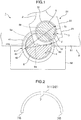
- Fig. 1 schematically shows a bearing device 1 of an internal combustion engine.
- the bearing device 1 includes a journal part 6, a crankpin 5, and a connecting rod 2.
- the journal part 6 is supported by a lower portion of a cylinder block 8.
- the crankpin 5 is integrally formed with the journal part 6 and rotates about the journal part 6.
- the connecting rod 2 transmits reciprocating motion from the internal combustion engine to the crankpin 5.
- the bearing device 1 further includes sliding bearings for supporting a crankshaft, one of which is a main bearing 4 rotatably supporting the journal part 6 and another of which is a connecting rod bearing 3 rotatably supporting the crankpin 5.
- journal part 6 and a single crankpin 5 in the drawings for convenience of description, while the crankshaft includes a plurality of journal parts 6 and a plurality of crankpins 5.
- the journal part 6 is located behind the crankpin 5 in Fig. 1 .
- crankpin 5 is pivotally supported by a large end housing 21 (a rod-side large end housing 22 and a cap-side large end housing 23) of the connecting rod 2 via the connecting rod bearing 3 constituted by a pair of half bearings 31 and 32.
- first lubrication oil passage 6a passes through the journal part 6 in the diameter direction of the journal part 6, and the entrance openings 6c of the first lubrication oil passage 6a communicate with the lubrication oil groove 41a.
- a second lubrication oil passage 5a passing through a crank arm part (not shown) branches off from the first lubrication oil passage 6a of the journal part 6, and communicates with a third lubrication oil passage 5b passing through the crankpin 5 in a diameter direction of the crankpin 5.
- the main bearing 4 and the connecting rod bearing 3 bear a dynamic load from the crankshaft by pressure generated in oil between a sliding surface of the main bearing 4 and the connecting rod bearing 3 and a surface of the shaft.
- a load is applied to the sliding surface of the main bearing 4 and the connecting rod bearing 3, and the load and its direction constantly change.
- Central axes of the journal part 6 and the crankpin 5 move eccentrically with respect to a bearing central axis of, respectively, the main bearing 4 and the connecting rod bearing 3 so that oil film pressure is generated proportionally to the load. Accordingly, a bearing gap of the main bearing 4 and the connecting rod bearing 3 (a gap between the surface of the shaft and the sliding surface) constantly changes at any position on the sliding surface.
- a maximum load is applied to a connecting rod bearing and a main bearing in a combustion stroke.
- the crankpin 5 moves in a direction (indicated by "arrow Q") (see Fig. 8 ) toward a portion of a sliding surface 7 near a circumferential center of the half bearing 31 on the upper side in Fig. 1 .
- the portion of the sliding surface near the circumferential center of the half bearing comes closest to a surface of the crankpin, and a load is applied in a direction toward the portion of the sliding surface near the circumferential center of the half bearing.
- a load is applied in a direction toward a portion of the sliding surface near a circumferential center of the half bearing provided on a bearing cap 82 side on a lower side in Fig. 1 , and the portion of the sliding surface near the circumferential center of the half bearing on the lower side comes closest to a surface of the journal part 6.
- a conventional half bearing having a sliding surface including a plurality of minute recesses has the following problems.
- oil in the recess is compressed to have high pressure, and flows out from the recess to a gap between the sliding surface and the surface of the shaft. As shown in Fig.
- the present invention addresses such problems of the conventional techniques.
- an exemplary half bearing of the present invention applied to the connecting rod bearing 3 will be described.
- the present invention is not limited to the connecting rod bearing 3, and may be configured as a half bearing for constituting the main bearing 4.
- Both of the pair of half bearings constituting the connecting rod bearing 3 or the main bearing 4 may be the half bearing of the present invention.
- only one of the pair of half bearings constituting the connecting rod bearing 3 or the main bearing 4 may be the half bearing of the present invention, and the other half bearing may be a conventional half bearing having no recesses on a sliding surface.
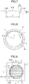
- Fig. 2 shows a first embodiment of the half bearing (for the connecting rod bearing 3) according to the present invention (viewed from an axial direction of the half bearing).
- the connecting rod bearing 3 is formed by combining the pair of half bearings 31, 32 into a cylindrical shape as a whole so that circumferential end faces 76 of the half bearing 31 are butted against circumferential end faces 76 of the half bearing 32.
- An inner surface of the cylindrical shape forms the sliding surface 7.
- the half bearing 31, 32 has a constant thickness in a circumferential direction.
- the half bearing 31, 32 may have a changing thickness so that the thickness is maximum at the circumferential center and is continuously decreased toward the circumferential end faces 76.
- Fig. 3 shows an example of recesses on the sliding surface of the half bearing.
- Fig. 4 shows an example of a recess viewed from a sliding surface side.
- the present invention is not limited to the embodiment.
- recesses 71 are exaggerated in the drawings.
- Fig. 4 shows the recess 71 having a circular opening on the sliding surface 7.
- the "circular" opening does not indicate a geometrically precise circular shape, and may be substantially circular.
- the recess 71 has a smooth surface 71S and a plurality of circumferential grooves 71G.
- the circumferential grooves 71G extend parallel to a circumferential direction M of the half bearing 31, 32.
- the circumferential groove 71G preferably extends from a peripheral edge to an opposite peripheral edge of the recess 71.
- the smooth surfaces 71S and the circumferential grooves 71G are alternately arranged in an axial direction of the half bearing 31, 32 in the recess 71.
- the term "smooth surface 71S" indicates a smooth surface having no grooves, protrusions, or the like, but may have minute (sufficiently small as compared with the circumferential grooves) asperities.
- the recess surface (the surface 71S of the recess excluding the circumferential grooves) is recessed toward an outer diameter side of the half bearing 31, 32 in a cross-sectional view (an A-A cross section in Fig. 4 ) in a direction parallel to the circumferential direction of the half bearing 31, 32. That is, the recess surface forms a convex curve toward the outer diameter side.
- the circumferential groove 71G in a cross-sectional view in the circumferential direction of the half bearing 31, 32 is also recessed from the recess surface toward the outer diameter side of the half bearing 31, 32.
- the recess 71 forms a curve recessed toward the outer diameter side of the half bearing 31, 32 also in a cross-sectional view in any direction other than the circumferential direction of the half bearing 31, 32.
- the "cross section” indicates a cross section perpendicular to the sliding surface 7.
- Fig. 6 shows, as an example, a surface of the recess 71 in a cross-sectional view (a B-B cross section in Fig. 4 ) in the axial direction of the half bearing.
- the circumferential grooves 71G extend from the peripheral edge of the recess 71 along a direction parallel to the circumferential direction of the half bearing 31, 32.
- the circumferential grooves 71G are allowed to be slightly tilted (up to 1°) with respect to the circumferential direction of the half bearing 31, 32.
- the circumferential grooves 71G preferably have a depth D2 (see Fig. 7 ) of 0.2 to 3 ⁇ m.
- the depth D2 of the circumferential grooves 71G is smaller than the depth D1 of the recess 71.
- the "depth of the circumferential groove” indicates a depth at a deepest part of the circumferential groove from the smooth surface adjacent to the circumferential groove, viewed in a cross-sectional view along a width direction of the circumferential groove.
- a width W of the circumferential groove 71G (i.e., a length of the circumferential groove 71G on the surface 71S of the recess 71 in the axial direction of the half bearing, see Fig. 7 ) is preferably 5 to 50 ⁇ m.
- the width W is preferably determined such that at least five circumferential grooves 71G can be formed in a single recess 71.
- the circumferential grooves 71G are arranged with a pitch P (i.e., a length between the deepest parts of the adjacent circumferential grooves 71G in the axial direction of the half bearing 31, 32, see Fig. 7 ) in the axial direction of the half bearing 31, 32.
- the pitch is preferably 5 to 100 ⁇ m.
- the depth D2 and the width W of the circumferential groove 71G may be changed along the length of the circumferential groove 71G.
- the "depth of the circumferential groove” and the “width of the circumferential groove” respectively indicate the maximum depth and the maximum width of the circumferential groove 71G, and the maximum values are preferably sized to meet the above described depth and width.
- the connecting rod bearing 3 of the embodiment is formed by combining a pair of half bearings into a cylindrical shape as a whole so that the circumferential end faces 76 of one of the half bearings are butted against the circumferential end faces 76 of the other half bearing.
- Both of the pair of half bearings are preferably the half bearing 31, 32 of the present invention.
- only one of the pair of half bearings may be the half bearing 31, 32 of the present invention.
- the half bearing 31, 32 may have a sliding layer made of a Cu bearing alloy or an Al bearing alloy.
- the half bearing 31, 32 may have a sliding layer made of a Cu bearing alloy or an Al bearing alloy on a back-metal layer made of an Fe alloy.
- the sliding surface 7 which is the inner surface of the cylindrical shape and includes an inner surface of the recess 71 may have a surface coating or overlay made of one of Bi, Sn, and Pb or an alloy thereof, which are softer than the bearing alloy.
- the surface coating may be made of a resin composition including synthetic resin as a main component. (Even in the case, the surface of the sliding layer is referred to as a "sliding surface" in this context).
- the surface of the recess 71 preferably does not have such a surface coating. If the surface of the recess 71 or a surface of the circumferential groove 71G has such a soft surface coating, when oil contains many foreign substances, the foreign substances are more likely to be embedded and accumulated. If the foreign substances are embedded and accumulated on the surface of the recess 71 or the surface of the circumferential grooves 71G, turbulence is more likely to occur in the oil flowing in the recess.
- the half bearing of the present invention has the recesses 71 on the sliding surface, and each recess 71 has the smooth surface 71S and the plurality of circumferential grooves 71G.
- the half bearing can reduce friction loss. A reason thereof will be described below.
- Fig. 8 shows a state where the surface of the shaft 5 separated from the sliding surface 7 of the half bearing 31 having the plurality of recesses 71 has moved relatively closer to the sliding surface 7, and the surface of the shaft 5 has come closest to the sliding surface 7.
- the oil in the recess 71 is compressed to have high pressure and flows out from the recess 71 into the gap between the sliding surface 7 and the shaft 5.
- the surface of the recess 71 has the plurality of circumferential grooves 71G extending in a direction parallel to the circumferential direction M of the half bearing 31.
- the surface of the shaft 5 comes closest to the portion of the sliding surface 7 near the circumferential center of the half bearing 31, 32, and the surface of the shaft 5 is more likely to directly come into contact with the sliding surface 7.
- the recess 71 of the half bearing 31, 32 of the embodiment is located closer to the circumferential center CL of the half bearing 31, 32, the area of the opening of the recess 71 is increased. Accordingly, when the surface of the shaft 5 comes closer to the sliding surface, in the recess 71 located closer to the circumferential center CL of the sliding surface 7, pressure of a larger amount of oil is increased, and thus the surface of the shaft 5 is less likely to directly come into contact with the portion of the sliding surface 7 near the circumferential center of the half bearing 31, 32.
- the recess 71 of the half bearing 31, 32 may be formed so that the recess 71 located closer to the circumferential end of the half bearing 31, 32 has an opening having a larger area on the sliding surface 7 and that the recess 71 located closer to the circumferential center CL has an opening having a smaller area.
- the recess 71 has a curved surface recessed toward the outer diameter side (convex toward the outer diameter side) of the half bearing 31, 32 not only in a cross-sectional view in a direction parallel to the circumferential direction of the half bearing 31, 32 and in a cross-sectional view in a direction parallel to the axial direction of the half bearing 31, 32 but also in a cross-sectional view in any direction other than the directions parallel to the circumferential direction and the axial direction of the half bearing 31, 32.
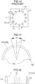
- Fig. 16 shows a recess 71 having a quadrilateral opening. Unlike in Fig. 15 , a diagonal line of the quadrilateral opening of the recess is parallel to the rotation direction Z of the shaft.
- the recess 71 has a curved surface recessed toward the outer diameter side (convex toward the outer diameter side) of the half bearing 31, 32 not only in a cross-sectional view in a direction parallel to the circumferential direction of the half bearing 31, 32 and in a cross-sectional view in a direction parallel to the axial direction of the half bearing 31, 32 but also in a cross-sectional view in any direction other than the directions parallel to the circumferential direction and the axial direction of the half bearing 31, 32.
- circumferential grooves 71G are omitted.
- circular, elliptical, and quadrilateral shapes are explained as the shape of the opening of the recess 71.
- these shapes of the opening do not indicate geometrically precise circular, elliptical, and quadrilateral shapes, and they may be substantially circular, elliptical, and quadrilateral.
- the shape of the opening of the recess 71 is not limited to these shapes, and other shapes may be applied.
- the half bearing of the present invention is applied to a connecting rod bearing for supporting a crankpin of a crankshaft of an internal combustion engine.
- the half bearing of the present invention is also applicable to one or both of a pair of half bearings constituting a main bearing for supporting a journal part of the crankshaft.
- the half bearing may have an oil hole or an oil groove.
- the half bearing may be configured such that a plurality of grooves extending in the circumferential direction of the half bearing are located throughout the sliding surface excluding the recesses 71.
Landscapes
- Engineering & Computer Science (AREA)
- General Engineering & Computer Science (AREA)
- Mechanical Engineering (AREA)
- Chemical & Material Sciences (AREA)
- Oil, Petroleum & Natural Gas (AREA)
- Sliding-Contact Bearings (AREA)
- Shafts, Cranks, Connecting Bars, And Related Bearings (AREA)
Applications Claiming Priority (1)
| Application Number | Priority Date | Filing Date | Title |
|---|---|---|---|
| JP2018099148A JP6871884B2 (ja) | 2018-05-23 | 2018-05-23 | 半割軸受およびすべり軸受 |
Publications (2)
| Publication Number | Publication Date |
|---|---|
| EP3572680A1 true EP3572680A1 (fr) | 2019-11-27 |
| EP3572680B1 EP3572680B1 (fr) | 2021-04-21 |
Family
ID=66589448
Family Applications (1)
| Application Number | Title | Priority Date | Filing Date |
|---|---|---|---|
| EP19175139.5A Active EP3572680B1 (fr) | 2018-05-23 | 2019-05-17 | Demi-roulement et roulement coulissant |
Country Status (4)
| Country | Link |
|---|---|
| US (1) | US10704591B2 (fr) |
| EP (1) | EP3572680B1 (fr) |
| JP (1) | JP6871884B2 (fr) |
| CN (1) | CN110529491B (fr) |
Families Citing this family (4)
| Publication number | Priority date | Publication date | Assignee | Title |
|---|---|---|---|---|
| JP7068410B2 (ja) * | 2020-09-28 | 2022-05-16 | 大同メタル工業株式会社 | ラジアルピストン機械の軸受装置 |
| JP7167108B2 (ja) * | 2020-09-28 | 2022-11-08 | 大同メタル工業株式会社 | ラジアルピストン機械の軸受装置 |
| JP7201719B2 (ja) * | 2021-02-12 | 2023-01-10 | 大同メタル工業株式会社 | 半割軸受およびすべり軸受 |
| JP7201720B2 (ja) * | 2021-02-12 | 2023-01-10 | 大同メタル工業株式会社 | 半割軸受およびすべり軸受 |
Citations (5)
| Publication number | Priority date | Publication date | Assignee | Title |
|---|---|---|---|---|
| JPS58149622U (ja) | 1982-03-31 | 1983-10-07 | いすゞ自動車株式会社 | 軸受装置 |
| JPH08277831A (ja) | 1995-04-03 | 1996-10-22 | Nissan Motor Co Ltd | 内燃機関のクランク潤滑装置 |
| EP0877866A2 (fr) * | 1996-01-30 | 1998-11-18 | GLYCO-METALL-WERKE Glyco B.V. & Co. KG | Element de palier lisse muni de poches d'huile lubrifiante |
| JP2008095721A (ja) | 2006-10-06 | 2008-04-24 | Nissan Motor Co Ltd | 摺動部材 |
| EP3486508A1 (fr) * | 2017-11-17 | 2019-05-22 | Daido Metal Company Ltd. | Demi-palier et palier lisse |
Family Cites Families (23)
| Publication number | Priority date | Publication date | Assignee | Title |
|---|---|---|---|---|
| US3133769A (en) * | 1961-04-13 | 1964-05-19 | Clevite Harris Products Inc | Permanently lubricated rubber bearing |
| DE2504204C3 (de) * | 1975-02-01 | 1981-11-12 | Skf Kugellagerfabriken Gmbh, 8720 Schweinfurt | Selbstdruckerzeugendes Axialgleitlager |
| DE2656306A1 (de) * | 1976-12-11 | 1978-06-15 | Glyco Metall Werke | Axialgleitlager |
| US5192136A (en) * | 1991-12-19 | 1993-03-09 | Federal-Mogul Corporation | Crankshaft bearing having hydrodynamic thrust flanges |
| GB9127191D0 (en) * | 1991-12-21 | 1992-02-19 | T & N Technology Ltd | Flanged bearings |
| JPH07305721A (ja) * | 1994-05-10 | 1995-11-21 | Mitsubishi Heavy Ind Ltd | 自動調心スラストすべり軸受 |
| JP3307871B2 (ja) * | 1998-01-12 | 2002-07-24 | 大同メタル工業株式会社 | 半割スラスト軸受 |
| US6511226B2 (en) * | 2000-09-05 | 2003-01-28 | Federal-Mogul World Wide, Inc. | Aluminum thrust washer |
| US6736729B2 (en) * | 2002-07-03 | 2004-05-18 | Gkn Automotive, Inc. | Constant velocity joint and method of making same |
| US7354199B2 (en) * | 2005-06-01 | 2008-04-08 | Federal Mogul Worldwide, Inc. | Thrust bearing |
| US20070081748A1 (en) * | 2005-10-06 | 2007-04-12 | Sitter Don H | Tab bearing |
| JP2007225079A (ja) * | 2006-02-27 | 2007-09-06 | Daido Metal Co Ltd | 斜め割りコンロッド用のすべり軸受 |
| JP4466687B2 (ja) * | 2007-06-20 | 2010-05-26 | 大豊工業株式会社 | 摺動部材とその製造方法 |
| DE102007055005B4 (de) * | 2007-11-14 | 2009-08-27 | Federal-Mogul Wiesbaden Gmbh | Anlaufscheibe und Radial-Axial-Lager mit einer solchen |
| JP4766141B2 (ja) * | 2009-03-31 | 2011-09-07 | 大豊工業株式会社 | 軸受装置 |
| JP2014163402A (ja) * | 2013-02-21 | 2014-09-08 | Daido Metal Co Ltd | 半割スラスト軸受および軸受装置 |
| US9664229B2 (en) * | 2013-04-26 | 2017-05-30 | GM Global Technology Operations LLC | Connecting rod |
| JP2015001250A (ja) * | 2013-06-14 | 2015-01-05 | 大同メタル工業株式会社 | 軸受装置 |
| JP5890808B2 (ja) * | 2013-08-26 | 2016-03-22 | 大同メタル工業株式会社 | 内燃機関のクランク軸用主軸受 |
| JP6100215B2 (ja) * | 2014-08-04 | 2017-03-22 | 大同メタル工業株式会社 | 半割スラスト軸受、及びそれを用いた軸受装置 |
| JP6092837B2 (ja) * | 2014-12-15 | 2017-03-08 | 大同メタル工業株式会社 | 内燃機関のクランク軸用軸受装置 |
| JP6529549B2 (ja) * | 2017-07-31 | 2019-06-12 | 大同メタル工業株式会社 | 半割軸受およびすべり軸受 |
| JP6595572B2 (ja) * | 2017-12-25 | 2019-10-23 | 大同メタル工業株式会社 | 半割スラスト軸受 |
-
2018
- 2018-05-23 JP JP2018099148A patent/JP6871884B2/ja active Active
-
2019
- 2019-05-17 EP EP19175139.5A patent/EP3572680B1/fr active Active
- 2019-05-20 US US16/416,611 patent/US10704591B2/en active Active
- 2019-05-22 CN CN201910429983.3A patent/CN110529491B/zh active Active
Patent Citations (6)
| Publication number | Priority date | Publication date | Assignee | Title |
|---|---|---|---|---|
| JPS58149622U (ja) | 1982-03-31 | 1983-10-07 | いすゞ自動車株式会社 | 軸受装置 |
| JPH08277831A (ja) | 1995-04-03 | 1996-10-22 | Nissan Motor Co Ltd | 内燃機関のクランク潤滑装置 |
| EP0877866A2 (fr) * | 1996-01-30 | 1998-11-18 | GLYCO-METALL-WERKE Glyco B.V. & Co. KG | Element de palier lisse muni de poches d'huile lubrifiante |
| JP2000504089A (ja) | 1996-01-30 | 2000-04-04 | グリコ―メタル―ウエルケ・グリコ・ベー・ファウ・ウント・コンパニー・コマンディトゲゼルシャフト | 潤滑油ポケットを有するすべり軸受要素 |
| JP2008095721A (ja) | 2006-10-06 | 2008-04-24 | Nissan Motor Co Ltd | 摺動部材 |
| EP3486508A1 (fr) * | 2017-11-17 | 2019-05-22 | Daido Metal Company Ltd. | Demi-palier et palier lisse |
Also Published As
| Publication number | Publication date |
|---|---|
| US10704591B2 (en) | 2020-07-07 |
| EP3572680B1 (fr) | 2021-04-21 |
| JP2019203559A (ja) | 2019-11-28 |
| CN110529491B (zh) | 2021-09-14 |
| CN110529491A (zh) | 2019-12-03 |
| US20190360520A1 (en) | 2019-11-28 |
| JP6871884B2 (ja) | 2021-05-19 |
Similar Documents
| Publication | Publication Date | Title |
|---|---|---|
| EP3572680B1 (fr) | Demi-roulement et roulement coulissant | |
| EP3502496B1 (fr) | Demi-palier axial | |
| EP3438476B1 (fr) | Demi-palier et palier glissant | |
| US11225998B2 (en) | Half bearing and sliding bearing | |
| US20190249711A1 (en) | Main bearing for crankshaft of internal combustion engine | |
| EP3534021B1 (fr) | Demi-palier axial | |
| KR20190046668A (ko) | 내연기관의 크랭크축용 주베어링 | |
| EP3486508B1 (fr) | Demi-palier et palier lisse | |
| US11261904B2 (en) | Half bearing and sliding bearing | |
| JP2023030707A (ja) | 半割軸受およびすべり軸受 | |
| KR20190046667A (ko) | 내연기관의 크랭크축용 커넥팅 로드 베어링 | |
| JP2023129836A (ja) | すべり軸受 |
Legal Events
| Date | Code | Title | Description |
|---|---|---|---|
| PUAI | Public reference made under article 153(3) epc to a published international application that has entered the european phase |
Free format text: ORIGINAL CODE: 0009012 |
|
| STAA | Information on the status of an ep patent application or granted ep patent |
Free format text: STATUS: REQUEST FOR EXAMINATION WAS MADE |
|
| 17P | Request for examination filed |
Effective date: 20190517 |
|
| AK | Designated contracting states |
Kind code of ref document: A1 Designated state(s): AL AT BE BG CH CY CZ DE DK EE ES FI FR GB GR HR HU IE IS IT LI LT LU LV MC MK MT NL NO PL PT RO RS SE SI SK SM TR |
|
| AX | Request for extension of the european patent |
Extension state: BA ME |
|
| STAA | Information on the status of an ep patent application or granted ep patent |
Free format text: STATUS: EXAMINATION IS IN PROGRESS |
|
| 17Q | First examination report despatched |
Effective date: 20200625 |
|
| GRAP | Despatch of communication of intention to grant a patent |
Free format text: ORIGINAL CODE: EPIDOSNIGR1 |
|
| STAA | Information on the status of an ep patent application or granted ep patent |
Free format text: STATUS: GRANT OF PATENT IS INTENDED |
|
| RIC1 | Information provided on ipc code assigned before grant |
Ipc: F16C 9/02 20060101AFI20201113BHEP Ipc: F16C 33/04 20060101ALI20201113BHEP Ipc: F16C 9/04 20060101ALN20201113BHEP Ipc: F16C 33/10 20060101ALI20201113BHEP |
|
| INTG | Intention to grant announced |
Effective date: 20201204 |
|
| GRAS | Grant fee paid |
Free format text: ORIGINAL CODE: EPIDOSNIGR3 |
|
| GRAA | (expected) grant |
Free format text: ORIGINAL CODE: 0009210 |
|
| STAA | Information on the status of an ep patent application or granted ep patent |
Free format text: STATUS: THE PATENT HAS BEEN GRANTED |
|
| AK | Designated contracting states |
Kind code of ref document: B1 Designated state(s): AL AT BE BG CH CY CZ DE DK EE ES FI FR GB GR HR HU IE IS IT LI LT LU LV MC MK MT NL NO PL PT RO RS SE SI SK SM TR |
|
| REG | Reference to a national code |
Ref country code: GB Ref legal event code: FG4D |
|
| REG | Reference to a national code |
Ref country code: CH Ref legal event code: EP |
|
| REG | Reference to a national code |
Ref country code: DE Ref legal event code: R096 Ref document number: 602019004003 Country of ref document: DE |
|
| REG | Reference to a national code |
Ref country code: IE Ref legal event code: FG4D |
|
| REG | Reference to a national code |
Ref country code: AT Ref legal event code: REF Ref document number: 1384935 Country of ref document: AT Kind code of ref document: T Effective date: 20210515 |
|
| REG | Reference to a national code |
Ref country code: LT Ref legal event code: MG9D |
|
| REG | Reference to a national code |
Ref country code: AT Ref legal event code: MK05 Ref document number: 1384935 Country of ref document: AT Kind code of ref document: T Effective date: 20210421 |
|
| REG | Reference to a national code |
Ref country code: NL Ref legal event code: MP Effective date: 20210421 |
|
| PG25 | Lapsed in a contracting state [announced via postgrant information from national office to epo] |
Ref country code: NL Free format text: LAPSE BECAUSE OF FAILURE TO SUBMIT A TRANSLATION OF THE DESCRIPTION OR TO PAY THE FEE WITHIN THE PRESCRIBED TIME-LIMIT Effective date: 20210421 Ref country code: BG Free format text: LAPSE BECAUSE OF FAILURE TO SUBMIT A TRANSLATION OF THE DESCRIPTION OR TO PAY THE FEE WITHIN THE PRESCRIBED TIME-LIMIT Effective date: 20210721 Ref country code: AT Free format text: LAPSE BECAUSE OF FAILURE TO SUBMIT A TRANSLATION OF THE DESCRIPTION OR TO PAY THE FEE WITHIN THE PRESCRIBED TIME-LIMIT Effective date: 20210421 Ref country code: FI Free format text: LAPSE BECAUSE OF FAILURE TO SUBMIT A TRANSLATION OF THE DESCRIPTION OR TO PAY THE FEE WITHIN THE PRESCRIBED TIME-LIMIT Effective date: 20210421 Ref country code: HR Free format text: LAPSE BECAUSE OF FAILURE TO SUBMIT A TRANSLATION OF THE DESCRIPTION OR TO PAY THE FEE WITHIN THE PRESCRIBED TIME-LIMIT Effective date: 20210421 Ref country code: LT Free format text: LAPSE BECAUSE OF FAILURE TO SUBMIT A TRANSLATION OF THE DESCRIPTION OR TO PAY THE FEE WITHIN THE PRESCRIBED TIME-LIMIT Effective date: 20210421 |
|
| PG25 | Lapsed in a contracting state [announced via postgrant information from national office to epo] |
Ref country code: PL Free format text: LAPSE BECAUSE OF FAILURE TO SUBMIT A TRANSLATION OF THE DESCRIPTION OR TO PAY THE FEE WITHIN THE PRESCRIBED TIME-LIMIT Effective date: 20210421 Ref country code: LV Free format text: LAPSE BECAUSE OF FAILURE TO SUBMIT A TRANSLATION OF THE DESCRIPTION OR TO PAY THE FEE WITHIN THE PRESCRIBED TIME-LIMIT Effective date: 20210421 Ref country code: NO Free format text: LAPSE BECAUSE OF FAILURE TO SUBMIT A TRANSLATION OF THE DESCRIPTION OR TO PAY THE FEE WITHIN THE PRESCRIBED TIME-LIMIT Effective date: 20210721 Ref country code: SE Free format text: LAPSE BECAUSE OF FAILURE TO SUBMIT A TRANSLATION OF THE DESCRIPTION OR TO PAY THE FEE WITHIN THE PRESCRIBED TIME-LIMIT Effective date: 20210421 Ref country code: PT Free format text: LAPSE BECAUSE OF FAILURE TO SUBMIT A TRANSLATION OF THE DESCRIPTION OR TO PAY THE FEE WITHIN THE PRESCRIBED TIME-LIMIT Effective date: 20210823 Ref country code: RS Free format text: LAPSE BECAUSE OF FAILURE TO SUBMIT A TRANSLATION OF THE DESCRIPTION OR TO PAY THE FEE WITHIN THE PRESCRIBED TIME-LIMIT Effective date: 20210421 Ref country code: GR Free format text: LAPSE BECAUSE OF FAILURE TO SUBMIT A TRANSLATION OF THE DESCRIPTION OR TO PAY THE FEE WITHIN THE PRESCRIBED TIME-LIMIT Effective date: 20210722 Ref country code: IS Free format text: LAPSE BECAUSE OF FAILURE TO SUBMIT A TRANSLATION OF THE DESCRIPTION OR TO PAY THE FEE WITHIN THE PRESCRIBED TIME-LIMIT Effective date: 20210821 |
|
| REG | Reference to a national code |
Ref country code: DE Ref legal event code: R097 Ref document number: 602019004003 Country of ref document: DE |
|
| PG25 | Lapsed in a contracting state [announced via postgrant information from national office to epo] |
Ref country code: SK Free format text: LAPSE BECAUSE OF FAILURE TO SUBMIT A TRANSLATION OF THE DESCRIPTION OR TO PAY THE FEE WITHIN THE PRESCRIBED TIME-LIMIT Effective date: 20210421 Ref country code: EE Free format text: LAPSE BECAUSE OF FAILURE TO SUBMIT A TRANSLATION OF THE DESCRIPTION OR TO PAY THE FEE WITHIN THE PRESCRIBED TIME-LIMIT Effective date: 20210421 Ref country code: ES Free format text: LAPSE BECAUSE OF FAILURE TO SUBMIT A TRANSLATION OF THE DESCRIPTION OR TO PAY THE FEE WITHIN THE PRESCRIBED TIME-LIMIT Effective date: 20210421 Ref country code: DK Free format text: LAPSE BECAUSE OF FAILURE TO SUBMIT A TRANSLATION OF THE DESCRIPTION OR TO PAY THE FEE WITHIN THE PRESCRIBED TIME-LIMIT Effective date: 20210421 Ref country code: CZ Free format text: LAPSE BECAUSE OF FAILURE TO SUBMIT A TRANSLATION OF THE DESCRIPTION OR TO PAY THE FEE WITHIN THE PRESCRIBED TIME-LIMIT Effective date: 20210421 Ref country code: MC Free format text: LAPSE BECAUSE OF FAILURE TO SUBMIT A TRANSLATION OF THE DESCRIPTION OR TO PAY THE FEE WITHIN THE PRESCRIBED TIME-LIMIT Effective date: 20210421 Ref country code: RO Free format text: LAPSE BECAUSE OF FAILURE TO SUBMIT A TRANSLATION OF THE DESCRIPTION OR TO PAY THE FEE WITHIN THE PRESCRIBED TIME-LIMIT Effective date: 20210421 Ref country code: SM Free format text: LAPSE BECAUSE OF FAILURE TO SUBMIT A TRANSLATION OF THE DESCRIPTION OR TO PAY THE FEE WITHIN THE PRESCRIBED TIME-LIMIT Effective date: 20210421 Ref country code: LU Free format text: LAPSE BECAUSE OF NON-PAYMENT OF DUE FEES Effective date: 20210517 |
|
| REG | Reference to a national code |
Ref country code: BE Ref legal event code: MM Effective date: 20210531 |
|
| PLBE | No opposition filed within time limit |
Free format text: ORIGINAL CODE: 0009261 |
|
| STAA | Information on the status of an ep patent application or granted ep patent |
Free format text: STATUS: NO OPPOSITION FILED WITHIN TIME LIMIT |
|
| 26N | No opposition filed |
Effective date: 20220124 |
|
| PG25 | Lapsed in a contracting state [announced via postgrant information from national office to epo] |
Ref country code: IE Free format text: LAPSE BECAUSE OF NON-PAYMENT OF DUE FEES Effective date: 20210517 |
|
| PG25 | Lapsed in a contracting state [announced via postgrant information from national office to epo] |
Ref country code: IS Free format text: LAPSE BECAUSE OF FAILURE TO SUBMIT A TRANSLATION OF THE DESCRIPTION OR TO PAY THE FEE WITHIN THE PRESCRIBED TIME-LIMIT Effective date: 20210821 Ref country code: AL Free format text: LAPSE BECAUSE OF FAILURE TO SUBMIT A TRANSLATION OF THE DESCRIPTION OR TO PAY THE FEE WITHIN THE PRESCRIBED TIME-LIMIT Effective date: 20210421 |
|
| PG25 | Lapsed in a contracting state [announced via postgrant information from national office to epo] |
Ref country code: IT Free format text: LAPSE BECAUSE OF FAILURE TO SUBMIT A TRANSLATION OF THE DESCRIPTION OR TO PAY THE FEE WITHIN THE PRESCRIBED TIME-LIMIT Effective date: 20210421 Ref country code: BE Free format text: LAPSE BECAUSE OF NON-PAYMENT OF DUE FEES Effective date: 20210531 |
|
| REG | Reference to a national code |
Ref country code: CH Ref legal event code: PL |
|
| PG25 | Lapsed in a contracting state [announced via postgrant information from national office to epo] |
Ref country code: LI Free format text: LAPSE BECAUSE OF NON-PAYMENT OF DUE FEES Effective date: 20220531 Ref country code: CH Free format text: LAPSE BECAUSE OF NON-PAYMENT OF DUE FEES Effective date: 20220531 |
|
| PG25 | Lapsed in a contracting state [announced via postgrant information from national office to epo] |
Ref country code: CY Free format text: LAPSE BECAUSE OF FAILURE TO SUBMIT A TRANSLATION OF THE DESCRIPTION OR TO PAY THE FEE WITHIN THE PRESCRIBED TIME-LIMIT Effective date: 20210421 |
|
| PG25 | Lapsed in a contracting state [announced via postgrant information from national office to epo] |
Ref country code: HU Free format text: LAPSE BECAUSE OF FAILURE TO SUBMIT A TRANSLATION OF THE DESCRIPTION OR TO PAY THE FEE WITHIN THE PRESCRIBED TIME-LIMIT; INVALID AB INITIO Effective date: 20190517 |
|
| P01 | Opt-out of the competence of the unified patent court (upc) registered |
Effective date: 20230623 |
|
| PG25 | Lapsed in a contracting state [announced via postgrant information from national office to epo] |
Ref country code: MK Free format text: LAPSE BECAUSE OF FAILURE TO SUBMIT A TRANSLATION OF THE DESCRIPTION OR TO PAY THE FEE WITHIN THE PRESCRIBED TIME-LIMIT Effective date: 20210421 |
|
| PG25 | Lapsed in a contracting state [announced via postgrant information from national office to epo] |
Ref country code: MT Free format text: LAPSE BECAUSE OF FAILURE TO SUBMIT A TRANSLATION OF THE DESCRIPTION OR TO PAY THE FEE WITHIN THE PRESCRIBED TIME-LIMIT Effective date: 20210421 |
|
| PGFP | Annual fee paid to national office [announced via postgrant information from national office to epo] |
Ref country code: DE Payment date: 20250521 Year of fee payment: 7 |
|
| PGFP | Annual fee paid to national office [announced via postgrant information from national office to epo] |
Ref country code: GB Payment date: 20250527 Year of fee payment: 7 |
|
| PGFP | Annual fee paid to national office [announced via postgrant information from national office to epo] |
Ref country code: FR Payment date: 20250528 Year of fee payment: 7 |
|
| PG25 | Lapsed in a contracting state [announced via postgrant information from national office to epo] |
Ref country code: TR Free format text: LAPSE BECAUSE OF FAILURE TO SUBMIT A TRANSLATION OF THE DESCRIPTION OR TO PAY THE FEE WITHIN THE PRESCRIBED TIME-LIMIT Effective date: 20210421 |