EP3572760B1 - Emballage ppour une transmission de chaleur et / ou de substance - Google Patents
Emballage ppour une transmission de chaleur et / ou de substance Download PDFInfo
- Publication number
- EP3572760B1 EP3572760B1 EP19174070.3A EP19174070A EP3572760B1 EP 3572760 B1 EP3572760 B1 EP 3572760B1 EP 19174070 A EP19174070 A EP 19174070A EP 3572760 B1 EP3572760 B1 EP 3572760B1
- Authority
- EP
- European Patent Office
- Prior art keywords
- rib
- package according
- strip portion
- foil elements
- flow channels
- Prior art date
- Legal status (The legal status is an assumption and is not a legal conclusion. Google has not performed a legal analysis and makes no representation as to the accuracy of the status listed.)
- Active
Links
Images




Classifications
-
- F—MECHANICAL ENGINEERING; LIGHTING; HEATING; WEAPONS; BLASTING
- F28—HEAT EXCHANGE IN GENERAL
- F28C—HEAT-EXCHANGE APPARATUS, NOT PROVIDED FOR IN ANOTHER SUBCLASS, IN WHICH THE HEAT-EXCHANGE MEDIA COME INTO DIRECT CONTACT WITHOUT CHEMICAL INTERACTION
- F28C3/00—Other direct-contact heat-exchange apparatus
- F28C3/06—Other direct-contact heat-exchange apparatus the heat-exchange media being a liquid and a gas or vapour
- F28C3/08—Other direct-contact heat-exchange apparatus the heat-exchange media being a liquid and a gas or vapour with change of state, e.g. absorption, evaporation, condensation
-
- F—MECHANICAL ENGINEERING; LIGHTING; HEATING; WEAPONS; BLASTING
- F28—HEAT EXCHANGE IN GENERAL
- F28F—DETAILS OF HEAT-EXCHANGE AND HEAT-TRANSFER APPARATUS, OF GENERAL APPLICATION
- F28F25/00—Component parts of trickle coolers
- F28F25/02—Component parts of trickle coolers for distributing, circulating, and accumulating liquid
- F28F25/08—Splashing boards or grids, e.g. for converting liquid sprays into liquid films; Elements or beds for increasing the area of the contact surface
- F28F25/087—Vertical or inclined sheets; Supports or spacers
-
- F—MECHANICAL ENGINEERING; LIGHTING; HEATING; WEAPONS; BLASTING
- F28—HEAT EXCHANGE IN GENERAL
- F28C—HEAT-EXCHANGE APPARATUS, NOT PROVIDED FOR IN ANOTHER SUBCLASS, IN WHICH THE HEAT-EXCHANGE MEDIA COME INTO DIRECT CONTACT WITHOUT CHEMICAL INTERACTION
- F28C1/00—Direct-contact trickle coolers, e.g. cooling towers
- F28C1/02—Direct-contact trickle coolers, e.g. cooling towers with counter-current only
-
- F—MECHANICAL ENGINEERING; LIGHTING; HEATING; WEAPONS; BLASTING
- F28—HEAT EXCHANGE IN GENERAL
- F28F—DETAILS OF HEAT-EXCHANGE AND HEAT-TRANSFER APPARATUS, OF GENERAL APPLICATION
- F28F25/00—Component parts of trickle coolers
- F28F25/02—Component parts of trickle coolers for distributing, circulating, and accumulating liquid
-
- F—MECHANICAL ENGINEERING; LIGHTING; HEATING; WEAPONS; BLASTING
- F28—HEAT EXCHANGE IN GENERAL
- F28F—DETAILS OF HEAT-EXCHANGE AND HEAT-TRANSFER APPARATUS, OF GENERAL APPLICATION
- F28F25/00—Component parts of trickle coolers
- F28F25/02—Component parts of trickle coolers for distributing, circulating, and accumulating liquid
- F28F25/06—Spray nozzles or spray pipes
-
- F—MECHANICAL ENGINEERING; LIGHTING; HEATING; WEAPONS; BLASTING
- F28—HEAT EXCHANGE IN GENERAL
- F28F—DETAILS OF HEAT-EXCHANGE AND HEAT-TRANSFER APPARATUS, OF GENERAL APPLICATION
- F28F25/00—Component parts of trickle coolers
- F28F25/10—Component parts of trickle coolers for feeding gas or vapour
-
- F—MECHANICAL ENGINEERING; LIGHTING; HEATING; WEAPONS; BLASTING
- F28—HEAT EXCHANGE IN GENERAL
- F28F—DETAILS OF HEAT-EXCHANGE AND HEAT-TRANSFER APPARATUS, OF GENERAL APPLICATION
- F28F3/00—Plate-like or laminated elements; Assemblies of plate-like or laminated elements
- F28F3/02—Elements or assemblies thereof with means for increasing heat-transfer area, e.g. with fins, with recesses, with corrugations
- F28F3/04—Elements or assemblies thereof with means for increasing heat-transfer area, e.g. with fins, with recesses, with corrugations the means being integral with the element
- F28F3/042—Elements or assemblies thereof with means for increasing heat-transfer area, e.g. with fins, with recesses, with corrugations the means being integral with the element in the form of local deformations of the element
- F28F3/046—Elements or assemblies thereof with means for increasing heat-transfer area, e.g. with fins, with recesses, with corrugations the means being integral with the element in the form of local deformations of the element the deformations being linear, e.g. corrugations
Definitions
- the invention relates to a packing for heat and / or mass transfer between liquid and gaseous media in countercurrent, in particular for water cooling by air in cooling towers, with a large number of film elements profiled by corrugations, the corrugations providing flow channels and the film elements being formed of contact points are arranged one behind the other in the thickness direction, with adjacent film elements being connected to one another at their contact points and with the large areas of adjacent film elements facing one another having a fine profile.
- Cooling towers for water cooling in general and cooling fixtures for cooling towers - also called packings - in particular are well known per se from the prior art.
- Cooling towers are used in particular to cool liquid media, i.e. fluids such as water, by means of ambient air.
- liquid media i.e. fluids such as water
- previously known cooling towers have a fluid cooling device which in turn has cooling components, that is to say so-called packings, and a fluid distribution device.
- the fluid to be cooled is sprayed above the packs by means of the fluid distribution device and trickles along the packs, namely downwards following the force of gravity.
- the packings are preferably flowed through by air for the purpose of cooling in countercurrent to the fluid to be cooled. As a result of the contact of the fluid to be cooled with the air inside the packs, the fluid to be cooled is cooled as intended.
- a fan which promotes the air flow through the cooling tower and in particular through the cooling installations. This is typically arranged in the vertical direction of the cooling tower above the fluid cooling device. In normal operation, the fan sucks in ambient air from below the fluid cooling device, which air flows through the fluid cooling device arranged in the vertical direction of the cooling tower below the fan as cooling air. The ambient air sucked in by the fan is released into the atmosphere as heated ambient air after flowing through the packs upwards.
- a cooling tower of the type described above is for example from WO 2009/149954 A1 known.
- a packing construction is known from the prior art, according to which a multiplicity of foil or plate elements profiled by corrugations is provided. These film elements are arranged one behind the other in the direction of thickness, the corrugations providing flow channels. Adjacent film elements are connected to one another at their points of contact. Furthermore, the large areas of adjacent film elements facing one another have a fine profile. This fine profiling serves to optimize the heat exchange even further.
- a generic pack is from the DE 41 22 369 C1 known.
- the built-in element consists of touching, folded lamellae made of film-like material, arranged parallel to the column axis.
- the folds of the lamellae lie at an angle to the column axis.
- the folding walls of the slats are also finely corrugated and the slats have a plurality of holes distributed over their surface.
- the corrugation results from roughening the surface of the lamellas by means of grooves or embossing patterns.
- the DE 39 18 483 A1 relates to a packing for heat and mass transfer in countercurrent.
- the filler body has a plurality of vertically and obliquely standing, superimposed and interconnected corrugated or folded foils or plates, which are designed and / or placed on top of one another and connected to one another such that the corrugations or folds of adjacent foils or plates cross.
- the corrugations or folds of neighboring foils or plates only intersect in the upper part of the filling body, while they run parallel to each other in the lower part.
- the US 6,578,829 B2 relates to a packaging section which has a plurality of vertically oriented, diagonally cross-shaped corrugated packaging sheets.
- the packaging sheets define a section height, the section having a base region, a volume region and a top region.
- the base region has a first specific geometry that differs from a geometry of the volume region.
- the upper area also has a specific, second geometry which also differs from the geometry of the volume area as well as from the geometry of the base area.
- the EP 0 056 911 B1 relates to a filling part for filling purposes in a water cooling tower, which in the basic state has vertical sheets of malleable material everywhere with a generally zig-zag-shaped, downward-pointing spiral pattern. Each sheet has a pair of opposite sides which are intended to be wetted by heated water flowing downwards over the same.
- the malleable material is equipped with horizontal ribs that form angled depressions. It is also provided that the filling part has water cooling pockets at the sinus curve between each rib and that the pockets of the depressions are arranged at an angle with respect to the horizontal.
- the EP 1 078 684 A1 discloses an ordered packing for separation columns which has profiled layers and channels arranged in them.
- the channels are oriented obliquely to a main flow direction.
- the layers are formed into a profile from film-like and fabric-like material strips.
- the invention proposes a packing of the type mentioned at the outset, which is characterized in that the fine profiling has ribs running transversely to the flow channels with rib webs and rib grooves, a rib groove being arranged between two adjacent rib webs, the transitions are formed between successive rib webs and rib grooves essentially free of radii.
- the fine profiling formed on the large surfaces of the film elements is formed according to the invention as ribbing.
- the ribbing runs transversely to the flow channels of the film elements.
- ribbing can be provided which runs parallel to the input or output edge of the film elements.
- the ribbing has rib webs on the one hand and rib grooves on the other hand, a rib groove being arranged between two adjacent rib webs. This results in an alternating arrangement of rib webs and rib grooves in the longitudinal direction of the film elements.
- the transitions between rib webs and rib grooves that follow one another in the longitudinal direction of the film elements or in the transverse direction of the ribs are formed essentially free of radii.
- “essentially” means a design without transition radii, provided that it is possible in particular from a production point of view. According to the invention, it is therefore important to avoid transition radii between the successive rib webs and rib grooves, so that the result is a "sharp-edged" configuration.
- transition radii between rib webs and rib grooves is therefore provided according to the prior art in order to be able to better remove the film elements, which are mostly made of a plastic material, from a molding tool. It was not recognized that transition radii minimize the barrier effect of fine profiling, which has a positive effect on the efficiency of a packing, and thus promote the formation of a laminar flow.
- the sharp edges of both the rib webs and the rib grooves which are now provided according to the invention as a departure from the prior art, provide a remedy here, since as a result of this structural design, turbulent flow conditions develop during operation, which causes an improved mixing of the two media involved, which ultimately leads to leads to an increased heat exchange.
- a disadvantage of the sharp-edged design of the transitions between rib webs and rib grooves provided according to the invention is that the gas-side, i.e. increased air-side pressure loss. This results in an increased energy expenditure for the fan for conveying the cooling air flowing through the pack.
- this disadvantage is deliberately accepted.
- the construction according to the invention achieves an overall increased overall efficiency. This has significant advantages for the operation of corresponding systems in a wide variety of branches of industry in the form of smaller and thus more cost-effective systems and overall lower total operating costs.
- the corrugations provide inclined flow channels in the longitudinal direction of the film elements, preferably zig-zag flow channels, the film elements being arranged alternately in the thickness direction so that the flow channels of adjacent film elements extend with opposite inclinations and under Cross training of the points of contact.
- the flow channels are not aligned in a straight line in the longitudinal direction of the film elements, but rather inclined thereto.
- a zigzag configuration is preferred.
- the inclination of the flow channels to the vertical has the positive effect that a flow path that is lengthened in relation to the height extension of the packing according to the invention results, which results in an improved heat exchange.
- the width of a rib web in particular the width of the plateau terminating a rib web on the upper side, can serve as a reference variable for the design of the transition radii. It is therefore proposed according to a further feature of the invention that the transition radii are formed ⁇ 20%, preferably ⁇ 10%, even more preferably ⁇ 5% of the rib web plateau width of the associated rib web. If the rib web plateau width measures, for example, 5 mm, the result is a transition radius of preferably ⁇ 0.5 mm, even more preferably of ⁇ 0.25 mm.
- transition radii The smaller the selected transition radii, the slower the demolding speed can be when a film element is demolded from the mold during manufacture. This disadvantage is consciously accepted with the design according to the invention, since the later efficiency of the film element formed in this way is significantly improved compared to the prior art. For manufacturing reasons, a transition radius of zero cannot be achieved. “Essentially” within the meaning of the invention therefore means that the transition radii are to be designed as small as possible when using conventional manufacturing processes. The more "sharp-edged" the rib design, the clearer the effect of a turbulent flow in normal operation.
- a rib groove has a groove depth of 2.0 mm to 3.0 mm, preferably 2.2 mm to 2.8 mm, even more preferably 2.4 mm to 2.6 mm, most preferably 2.5 mm.
- a groove depth in the specified range achieves an optimized degree of efficiency. If the groove depth falls significantly smaller or significantly larger, then flow effects occur on the rib webs and / or the rib grooves in normal operation, which oppose an effective heat and / or mass transfer between the media involved.
- a rib groove has a groove width of 4.0 mm to 6.0 mm, preferably of 5.0 mm.
- the large surfaces of the film elements facing one another with fine profiling as comprehensively as possible in the sense of the invention.
- only some areas of the large surfaces of the film elements are to be left out, such as, for example, the input and output end regions of the film elements.
- a further feature of the invention can provide that the inclination of the flow channels to the vertical in the final assembled state is ⁇ 22 °, preferably between 19 ° and 15 °, even more preferably 17 °.
- the inclination of the flow channels to the vertical has the positive effect of lengthening the total flow path to be covered, which also results in improved heat and / or mass transfer.
- the greater the inclination to the vertical the greater the pressure loss that occurs in the air flow during operation. In the manner already described, this leads to an inevitably necessary increase in the fan output, which has a negative effect on the overall energy balance.
- the aim is basically to have the flow channels parallel in To run in the longitudinal direction, which then again leads to a deteriorated heat and / or mass transfer due to the shortened flow path.
- the fine profiling according to the invention makes it possible to bring these conflicting interests into an optimized balance with one another. This enables increased heat and / or mass transfer, so that in order to minimize the pressure loss in the cooling air it is possible to make the angle of inclination of the flow channels to the vertical smaller than usual, namely smaller than 20 °. This was not to be expected against the background of the known prior art.
- the groove depth averaged over the groove width is preferred as the groove depth in the context of the invention.
- the groove depth with reference to the groove width in the middle of the groove can be used as a reference value.
- the end regions of a film element which are opposite one another in the longitudinal direction are designed without fine profiling.
- grooves running obliquely to the longitudinal extension of the film elements are formed. These grooves are preferably formed in the film elements on the liquid inlet side and the liquid outlet side of the pack. They serve in particular to allow the liquid to flow out of the pack after flowing through the pack in an improved manner and to allow it to drip off. As a result of this measure, a reduced pressure loss on the gas or air side is also achieved.
- two channels are provided for each flow channel, which are aligned with one another in a V-shape.
- the liquid film that forms on the inner side walls of the flow channels in the intended use can thus flow off better on the outlet side without the formation of liquid waves that would create an increased resistance to the air flowing in the opposite direction, as is the case with the prior art.
- This improved outflow or dripping effect can also be supported by the fact that the two channels open into a common outlet which is oriented in the direction of the longitudinal extension of the film elements. This results in structures similar to ⁇ on the outlet side of the flow channels, which results in an improved outflow of the liquid applied to the packing.
- the mutually facing flow channels of adjacent film elements form a film or plate pair channel which has a hexagonal channel cross section on the inlet and outlet sides.
- each film element provides a flow channel that is open on one side.
- these flow channels of the individual film elements interact with the respective formation of a film pair channel.
- the film pair channels preferably have a channel cross-section that is polygonal, preferably hexagonal.
- the division dimension that is to say the height of each flow channel in the depth of the formation of the film element, is preferably 12 mm, 20 mm or 30 mm. This results in a channel width for a film pair channel of 24 mm, 40 mm or 60 mm on the input or output side of the pack, based on the film spacing or film division.
- the corrugations of the film elements have a polygonal channel cross-section on the input or output side, preferably a hexagonal cross-section, the edge lengths of which are preferably of different lengths.
- the corrugations of the film elements have a first strip section running in the longitudinal direction of the film elements and a second and third longitudinal strip arranged thereon along its respective longitudinal edges, the second and third strip sections being oriented at an incline to the first strip section.
- the second and third strip sections are designed to be of equal width and each have a width that exceeds the width of the first strip section. So the smaller the short edge length, i.e.
- the preferred ratio of short to long hexagonal sides i.e. the width ratio of the first strip section and the second strip section or third strip section is between 0.3 and 0.4, preferably 0.35. This results in a favorable for an optimized heat and mass transfer, i.e. as uniform as possible a thickness of the liquid film forming on the surfaces of the flow channels.
- the width of the first strip section or the short edge length of the channel cross-section depends on the pitch, but is at least 5 mm. With a 20 division, for example, the edge length is between 8 mm and 12 mm, preferably 10 mm. If the short edge length, ie the width of the first strip section, is significantly below these value parameters, a comparatively narrow liquid channel is created, which in the case of operation leads to a collection of liquid in this Can lead channel and what reduces the overall effectiveness of the packing according to the invention.
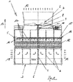
- Fig. 1 shows a cooling tower 1 as it is from the prior art, for example according to the WO 2009/149954 A1 is known.
- the cooling tower 1 has a liquid cooling device, which in turn has a liquid distribution device 14 on the one hand and cooling fixtures 12 on the other.
- the liquid distribution device 14 is arranged in the vertical direction 13 above the cooling fixtures 12.
- the liquid distribution device 14 has a plurality of distribution pipes 15 which are connected to a common inlet pipe 5 on the liquid side.
- the distribution pipes 15 of the liquid distribution device 14 are equipped on the cooling component side with nozzles 16 which, when in operation, distribute the liquid fed to the liquid distribution device 14, for example water, in the direction of the arrows 17 to the cooling components 12.
- the cooling tower 1 uses a suction fan wheel 8 as the cooling medium to supply ambient air in accordance with arrows 18 and 19 with reference to the plane of the drawing Fig. 1 guided from bottom to top.
- the cooling fixtures 12 which in the embodiment shown are designed in three layers.
- the liquid to be cooled by means of the cooling tower 1, for example water, is introduced into the liquid distribution device 14 via the feed pipe 5.
- the distance between the outlet openings of the nozzles 16 and the upper edge of the cooling fixtures 12 determines the spray height, which is 600 mm, for example.
- the water evenly distributed over the cooling fixtures 12 by means of the liquid distribution device 14 trickles through the cooling fixtures 12 in countercurrent to the cooling air conveyed from the bottom to the top.
- the water that has cooled down after trickling through the cooling fittings 12 drips off from the cooling fittings 12 and is collected in the water collecting pan 3.
- support struts 6 are provided to support the liquid cooling device against the water collecting trough 3, which support the liquid cooling device, ie the liquid distribution device 14 and the cooling components 12.
- a cooling tower jacket 2, which houses the fan wheel 8, is provided in the vertical direction 13 above the liquid cooling device.
- the fan wheel 8 is part of an axial fan 7, which also has a gear arrangement 9, a motor 10 and a shaft 11 coupling the motor 10 to the gear arrangement 9.
- the gear arrangement 9, together with the fan wheel 8, is supported by a column 4 protruding through the liquid cooling device.
- the cooling fixtures 12 provided in the vertical direction 13 below the liquid distribution device 14 contain packings of the type according to the invention, the structure of which is derived from the other Figures 2 to 13 results.
- a pack 20 according to the invention for a heat and / or Mass transfer between liquid and gaseous media in countercurrent, in particular for water cooling by air in a cooling tower 1 Fig. 1 , has a multiplicity of film elements 21 profiled by corrugations 22.
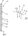
- Such a film element 21 is shown in a first embodiment in FIG Fig. 2 shown in a side view.
- the corrugations 22 of the film element 21 provide flow channels 25, as can be seen in particular from the sectional view Fig. 3 reveals.
- the corrugation 22 of the film element 21 is composed of successive wave crests 23 and wave troughs 24, a wave trough 24 being arranged between two wave crests and a wave crest 23 between two wave troughs 24.
- the corrugation 22 provides flow channels 25 both on the top side and on the underside of the film element 21.
- the flow channels 25 run as shown in the view Fig. 2 can be seen in the longitudinal direction 26 of the film element 21, ie in the intended installation in the vertical direction from top to bottom or from bottom to top.
- the preferred embodiment of the invention according to the Figures 1 to 7 shows a film element 21, accordingly the corrugations 22 provide flow channels 25 running inclined in the longitudinal direction 26, namely flow channels 25 running in a zigzag shape.
- the film elements 21 provided for forming a pack 20 according to the invention are arranged alternately in the thickness direction 40 - also called the depth direction - as can be seen from the illustration Fig. 8 results, so that the flow channels 25 of adjacent film elements 21 extend with opposite inclination and intersect with one another to form contact points 29.
- adjacent film elements 21 are connected to one another, for example by gluing and / or welding.
- the film elements 21 have their large surfaces 30 according to FIG Fig. 5 each has a fine profiling 31.
- This fine profiling 31, also called micro-corrugation or microstructure, has ribbing 32 running transversely to the flow channels 25 Rib webs 33 and rib grooves 34, as can be seen in particular from the side view Fig. 4 and the sectional view Fig. 5 results.
- a rib groove 34 is arranged between two adjacent rib webs 33 of the ribbing 32.
- the transitions between successive rib webs 33 and rib grooves 34 are designed essentially free of radii. To this extent, there is a sharp-edged transition between the rib webs 33 and the rib grooves 34.
- “essentially” designed without radii means a configuration without transition radii, provided that this is possible in particular from a production point of view. It is therefore important to avoid transition radii between the successive rib webs 33 and rib grooves 34, so that the result is a "sharp-edged" configuration. “Essentially” within the meaning of the invention means in particular that the transition radii are to be designed as small as possible in the context of the use of conventional manufacturing processes. This is because the more “sharp-edged" the rib design, the more clearly the effect of a turbulent flow that is desirable to be achieved occurs in normal operation.
- the end regions 35 of the film element 21 lying opposite one another in the longitudinal direction 26 are free of fine profiling. This ensures in particular an improved exit of water from the pack 20 according to the invention.
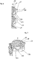
- This positive effect is further supported according to the invention by the fact that grooves 36 and 37 running obliquely to the longitudinal extension 26 of the film elements 21 are formed in the finely profiled end regions 35 of the film elements 21, like this a synopsis of the Figures 6 and 7 reveals.
- a film element 21 has two channels 36 and 37 for each flow channel 25, which are aligned with one another in a V-shape. These two channels 36 and 37 open into a common outlet 38 which is oriented in the direction of the longitudinal extension 26 of the film elements 21.
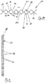
- FIGS. 8 and 10 show a pack 20 according to the invention which, for the sake of clarity, has only two in the illustrated embodiment Thickness direction 40 has foil elements 21 arranged one behind the other.
- the pack 20 When used as intended, the pack 20 is shown with reference to the plane of the drawing Fig. 8 charged with air from below, as indicated by the arrows 27. The air flows into the flow channels 25, flows through the pack 20 and leaves it with reference to the plane of the drawing Fig. 8 on top again. In countercurrent to this, the pack 20 is charged with water, specifically with reference to the plane of the drawing Fig. 8 from above in correspondence with the arrows 28. The water trickles through the pack 20 with reference to the plane of the drawing Fig. 8 from top to bottom and leaves the pack 20 with respect to the plane of the drawing Fig. 8 over the lower end region 35.
- the flow channels 25 of the film elements 21 arranged one behind the other in the thickness direction 40 complement one another to form film pair channels 39, as is shown in particular in the sectional illustration Fig. 10 reveals.
- the film elements 21 arranged one behind the other in the direction of thickness 40 each provide zigzag running flow channels 25, the flow channels 25 of adjacent film elements 21 extending with opposite inclination and crossing one another to form the contact points 29.
- the wave peaks 23 and wave troughs 24 of a corrugation 22 of the profile elements 21 adjoin one another in the width direction 41, as is also the case Fig. 11 can be seen.
- the film elements 21 are equipped with flow channels 25 running in a straight line in the longitudinal direction 26, the flow channels 25 being divided into sections which are offset from one another in the width direction 41.
- the flow channels 25 are divided into sections which are offset from one another in the width direction 41.
- the fine profiling 31 of the film elements 21 extends over the entire surface of the large areas 30 with the exception of the end region 35.
- the alternative Embodiment according to the Figures 12 and 13 shows a fine profiling 31, which is interrupted in the longitudinal direction 26 of the film element 21 by areas 42 without fine profiling. Such a configuration can arise in particular for manufacturing reasons.
- the fine profiling according to the invention is formed by ribbing 32, as already described above with reference to FIG Fig. 5 described.
- the ribbing 32 has rib webs 33 and rib grooves 34 following one another in the longitudinal direction 26, each rib web 33 providing a rib web plateau 43.
- the transitions between successive rib webs 33 and rib grooves 34 are formed essentially without radii.
- the width of the rib web plateaus 43 that is to say with regard to the extent of the rib web plateaus 43 in the longitudinal direction 26, it is preferred that the transition radii ⁇ 20%, preferably ⁇ 10%, even more preferably ⁇ 5% of the rib web plateau width of the associated rib web 33 are trained.
- the combination of the flow channels 25 of two adjacent film elements 21 results in a film pair channel 39, as shown in the sectional illustration Fig. 10 in particular reveals.
- a polygonal, preferably hexagonal configuration of the film pair channel 39 is preferred, as in FIG Fig. 10 shown.
- a flow channel 25 delimited by three strip elements 44, 45 and 46 is provided for each film element 21.
- the edge lengths, that is to say the widths of the strip elements 44, 45 and 46 differ from one another.
- the width of the strip elements 45 and 46 that is, their edge length in relation to the cross section, is the same size and exceeds the width of the first strip section 44 or, in relation to the cross section, its edge length.
- the edge length S1 of the first strip element 44 and the edge lengths S2 of the second strip element 45 and third strip element 46 are shown in FIG Fig. 10 drawn in as an example.
- the width or edge ratio S1 / S2 is preferably between 0.3 and 0.4, most preferably 0.35.
Landscapes
- Engineering & Computer Science (AREA)
- Mechanical Engineering (AREA)
- General Engineering & Computer Science (AREA)
- Physics & Mathematics (AREA)
- Thermal Sciences (AREA)
- Physical Or Chemical Processes And Apparatus (AREA)
- Packages (AREA)
- Heat-Exchange Devices With Radiators And Conduit Assemblies (AREA)
Claims (13)
- Emballage pour un transfert de chaleur et/ou de matière entre des milieux liquides et gazeux en contre-courant, notamment pour le refroidissement d'eau par moyen d'air dans des tours de refroidissement, comprenant une pluralité d'éléments en feuilles (21) profilés par des ondulations (22), les ondulations (22) fournissant des canaux d'écoulement (25) et les éléments en feuilles (21) étant disposés l'un derrière l'autre dans la direction de l'épaisseur (40) en formant des points de contact (29), dans lequel des éléments en feuilles (21) adjacents sont reliés l'un à l'autre dans leurs points de contact (29) et dans lequel les grandes surfaces (30) des éléments en feuilles (21) adjacents, lesquelles se font face, comprennent un profilage fin (31), caractérisé en ce que le profilage fin (31) comprend un crénelage (32) ayant des entretoises de nervure (33) et des encoches de nervure (34), lequel crénelage (32) s'étend transversalement par rapport aux canaux d'écoulement (25), dans lequel une encoche de nervure (34) est formée entre deux entretoises de nervure (33) adjacentes, les transitions entre des entretoises de nervure (33) et des encoches de nervure (34) successives étant essentiellement formées sans rayons.
- Emballage selon la revendication 1, caractérisé en ce que les ondulations (22) fournissent des canaux d'écoulement (25) inclinés dans la direction longitudinale (26) des éléments en feuilles (21) et s'étendant de préférence en forme de zigzag, dans lequel les éléments en feuilles (21) sont disposés de manière alternant dans la direction de l'épaisseur (40), de sorte que les canaux d'écoulement (25) des éléments en feuilles (21) adjacents s'étendent avec une inclinaison opposée et se croisent en formant les points de contact (29).
- Emballage selon la revendication 1 ou la revendication 2, caractérisé en ce que les rayons de transition sont plus petits de 20%, de préférence plus petits de 10%, de préférence particulière plus petits de 5% que la largeur de plateau de l'entretoise de nervure de l'entretoise de nervure associée (33).
- Emballage selon l'une des revendications précédentes, caractérisé en ce qu'une encoche de nervure (34) a une profondeur d'encoche comprise entre 2 mm et 3 mm, de préférence entre 2,2 mm et 2,8 mm, de préférence particulière entre 2,4 mm et 2,6 mm, le plus préférablement de 2,5 mm.
- Emballage selon l'une des revendications précédentes, caractérisé en ce que les parties d'extrémité (35) d'un élément en feuilles (21), lesquelles se font face dans la direction longitudinale (26), sont formées sans profilage fin.
- Emballage selon la revendication 5, caractérisé en ce que des rainures (36, 37), qui s'étendent obliquement par rapport à l'extension longitudinale (26) des éléments en feuilles (21) sont formées dans les parties d'extrémité (35) sans profilage fin des éléments en feuilles (21), dans lesquelles rainures débouchent les canaux d'écoulement (25).
- Emballage selon la revendication 6, caractérisé en ce qu'un élément en feuilles (21) comprend deux rainures (36, 37) pour chaque canal d'écoulement (25), lesquelles rainures sont alignées l'une par rapport à l'autre sous forme d'un V.
- Emballage selon la revendication 7, caractérisé en ce que les deux rainures (36, 37) débouchent dans une sortie (38) commune, qui est orientée dans la direction de l'extension longitudinale (26) des éléments en feuilles (21).
- Emballage selon l'une des revendications précédentes, caractérisé en ce que les canaux d'écoulement (25), qui se font face, d'éléments en feuilles (21) adjacents forment un canal de paire en feuilles (39), qui comprend une section transversale de canal polygonale, de préférence hexagonale, à l'entrée et à la sortie.
- Emballage selon l'une des revendications précédentes, caractérisé en ce que les ondulations (22) des éléments en feuilles (21) comprennent une première partie de bande (44) s'étendant dans la direction longitudinale (26) des éléments en feuilles (21) ainsi qu'une deuxième et une troisième partie de bande (45, 46) disposées le long des bords longitudinaux respectifs de la première partie de bande (44), dans lequel la deuxième et la troisième partie de bande (45, 46) sont orientées de manière inclinée par rapport à la première partie de bande (44).
- Emballage selon la revendication 10, caractérisé en ce que la deuxième et la troisième partie de bande (45, 46) comprennent la même largeur et comprennent chacune une largeur, qui excède la largeur de la première partie de bande (44).
- Emballage selon la revendication 11, caractérisé en ce que le rapport de largeur entre la première partie de bande (44) et la deuxième partie de bande (45) ou entre la première partie de bande (44) et la troisième partie de bande (46) est compris entre 0,3 et 0,4, et est de préférence 0,35.
- Emballage selon la revendication 10 ou la revendication 11, caractérisé en ce que la largeur de la première partie de bande est au moins 5 mm, de préférence comprise entre 7 mm et 18 mm, de préférence particulière comprise entre 8,5 mm et 9,5 mm.
Applications Claiming Priority (1)
| Application Number | Priority Date | Filing Date | Title |
|---|---|---|---|
| DE202018102787.5U DE202018102787U1 (de) | 2018-05-18 | 2018-05-18 | Packung für eine Wärme- und/oder Stoffübertragung |
Publications (2)
| Publication Number | Publication Date |
|---|---|
| EP3572760A1 EP3572760A1 (fr) | 2019-11-27 |
| EP3572760B1 true EP3572760B1 (fr) | 2020-09-09 |
Family
ID=66529859
Family Applications (1)
| Application Number | Title | Priority Date | Filing Date |
|---|---|---|---|
| EP19174070.3A Active EP3572760B1 (fr) | 2018-05-18 | 2019-05-13 | Emballage ppour une transmission de chaleur et / ou de substance |
Country Status (3)
| Country | Link |
|---|---|
| US (1) | US11175097B2 (fr) |
| EP (1) | EP3572760B1 (fr) |
| DE (1) | DE202018102787U1 (fr) |
Families Citing this family (7)
| Publication number | Priority date | Publication date | Assignee | Title |
|---|---|---|---|---|
| WO2020031753A1 (fr) * | 2018-08-09 | 2020-02-13 | 富士電機株式会社 | Refroidisseur et module à semi-conducteur |
| CN110801795A (zh) * | 2019-11-26 | 2020-02-18 | 衡阳旭光锌锗科技有限公司 | 一种反应釜快速降温装置 |
| CA3198497A1 (fr) * | 2021-02-05 | 2022-08-11 | Evapco, Inc. | Remplissage d'echange de chaleur direct techclean |
| US12228352B2 (en) * | 2021-02-05 | 2025-02-18 | Evapco, Inc. | Techclean direct heat exchange fill |
| CN113074574B (zh) * | 2021-04-29 | 2023-01-24 | 西安西热节能技术有限公司 | 一种基于主导风向的湿式冷却塔填料布置结构 |
| CN115945159A (zh) * | 2022-12-09 | 2023-04-11 | 北京泽华化学工程有限公司 | 波纹规整填料及用于气液交换容器的填料区 |
| KR20250140612A (ko) * | 2023-02-06 | 2025-09-25 | 브렌트우드인더스트리즈인코포레이티드 | 충전 시트용 미세 구조물 |
Family Cites Families (21)
| Publication number | Priority date | Publication date | Assignee | Title |
|---|---|---|---|---|
| US1847216A (en) * | 1928-03-31 | 1932-03-01 | Garlock Packing Co | Packing |
| US3618778A (en) * | 1969-05-22 | 1971-11-09 | Ethyl Corp | Liquid-treating apparatus |
| BE788776A (fr) * | 1970-05-07 | 1973-01-02 | Serck Industries Ltd | Dispositif de refroidissement d'un liquide |
| CH618006A5 (fr) * | 1977-05-12 | 1980-06-30 | Sulzer Ag | |
| CH617357A5 (fr) * | 1977-05-12 | 1980-05-30 | Sulzer Ag | |
| US4361426A (en) * | 1981-01-22 | 1982-11-30 | Baltimore Aircoil Company, Inc. | Angularly grooved corrugated fill for water cooling tower |
| EP0229199B1 (fr) * | 1985-12-17 | 1990-10-31 | H-PANNONPLAST Müanyagipari Vallalat | Garnissage à écoulement en film pour traitement biologique de fluides |
| US4801410A (en) * | 1987-07-02 | 1989-01-31 | The Marley Cooling Tower Company | Plastic fill sheet for water cooling tower with air guiding spacers |
| US4929399A (en) * | 1988-03-17 | 1990-05-29 | Union Carbide Industrial Gases Technology Inc. | Structured column packing with liquid holdup |
| DE8904345U1 (de) * | 1989-04-07 | 1989-05-18 | Streng, Andreas, Dipl.-Ing., 5210 Troisdorf | Wärme- und Stoffübertrager |
| DE3918483A1 (de) * | 1989-06-06 | 1990-12-13 | Munters Euroform Gmbh Carl | Fuellkoerper |
| US5124087A (en) * | 1990-10-04 | 1992-06-23 | Evapco International, Inc. | Gas and liquid contact body |
| DE4122369C1 (en) | 1991-07-05 | 1992-10-22 | Rainer Richter Gmbh, 5439 Hof, De | Packaging used for heat and mass transfer between liq. and gas - consists of corrugated or folded foil, plate or mat-like packaging elements in zones, in which profiles are inclined to longitudinal axis, etc. |
| US5454988A (en) * | 1994-01-12 | 1995-10-03 | Mitsubishi Corporation | Packing to be used in substance and/or heat exchanging tower |
| US5616289A (en) * | 1994-01-12 | 1997-04-01 | Mitsubishi Corporation | Substance and/or heat exchanging tower |
| EP1078684A1 (fr) * | 1999-08-24 | 2001-02-28 | Sulzer Chemtech AG | Garnissage structuré pour des colonnes de séparation |
| US6478290B2 (en) * | 1999-12-09 | 2002-11-12 | Praxair Technology, Inc. | Packing for mass transfer column |
| DE202008007932U1 (de) | 2008-06-13 | 2008-08-21 | Streng, Andreas | Vollkegeldüse |
| US8622115B2 (en) * | 2009-08-19 | 2014-01-07 | Alstom Technology Ltd | Heat transfer element for a rotary regenerative heat exchanger |
| US20120049392A1 (en) * | 2010-08-25 | 2012-03-01 | Carlos Jose Trompiz | Structured Packing with Extended Contact Area |
| US20160223262A1 (en) * | 2014-10-31 | 2016-08-04 | Baltimore Aircoil Company, Inc. | Cooling tower integrated inlet louver fill |
-
2018
- 2018-05-18 DE DE202018102787.5U patent/DE202018102787U1/de not_active Expired - Lifetime
-
2019
- 2019-05-13 EP EP19174070.3A patent/EP3572760B1/fr active Active
- 2019-05-16 US US16/413,926 patent/US11175097B2/en active Active
Non-Patent Citations (1)
| Title |
|---|
| None * |
Also Published As
| Publication number | Publication date |
|---|---|
| US20190353425A1 (en) | 2019-11-21 |
| EP3572760A1 (fr) | 2019-11-27 |
| US11175097B2 (en) | 2021-11-16 |
| DE202018102787U1 (de) | 2019-08-22 |
Similar Documents
| Publication | Publication Date | Title |
|---|---|---|
| EP3572760B1 (fr) | Emballage ppour une transmission de chaleur et / ou de substance | |
| EP0069241B1 (fr) | Garniture pour colonnes d'échange de matières et procédé de fabrication de la garniture | |
| EP1992898B1 (fr) | Echangeur thermique pour fluides caloporteurs gazeux | |
| DE69914705T2 (de) | Füllkörper mit Filmströmung, mit Gaswirbelströmung für Kontaktvorrichtung mit Stoff- und Wärmeaustausch, mit Rieselplatten mit Distanzstücken | |
| DE3107010C2 (de) | Metallkühler zum Kühlen eines unter hohem Druck durchströmenden Fluids durch Luft | |
| DE3148375C2 (fr) | ||
| EP2408553B1 (fr) | Installation d'emballage pour un emballage structuré | |
| EP2496342B1 (fr) | Grille de garniture ondulée et garniture ordonnée, constituée de plusieurs grilles de garniture | |
| EP2045556B1 (fr) | Echangeur thermique à plaques | |
| EP0529422A1 (fr) | Elément de remplissage | |
| DE102006048305A1 (de) | Plattenwärmetauscher | |
| DE10220532A1 (de) | Wärmetauscher | |
| CH691328A5 (de) | Deckenelement für eine Heiz- und Kühldecke. | |
| EP2932181B1 (fr) | Ensemble de plaques, échangeur de matières gaz-gaz et installation de ventilation de bâtiment | |
| DE3347086A1 (de) | Matrix fuer einen katalytischen reaktor zur abgasreinigung | |
| EP1182416A2 (fr) | Tube d'échangeur de chaleur avec ailettes intérieures décalées et de hauteur variable | |
| CH666538A5 (de) | Waermeuebertrager mit mehreren parallelen rohren und auf diesen angebrachten rippen. | |
| EP2310756B1 (fr) | Élément intégrable à intégrer dans un dispositif d'humidification, de nettoyage et/ou de refroidissement d'un fluide, en particulier d'un gaz comme l'air par exemple, et procédé de fabrication d'un corps intégrable avec un tel élément intégrable | |
| DE2613747B2 (de) | Röhrenwärmetauscher | |
| EP3433544B1 (fr) | Module à insérer dans un dispositif d'humidification, de purification et/ou de refroidissement d'un fluide, en particulier d'un gaz comme l'air par exemple | |
| EP1625339B1 (fr) | Echangeur de chaleur | |
| DE69605347T2 (de) | Wärmetauscher mit gelöteten Platten | |
| DE4122369C1 (en) | Packaging used for heat and mass transfer between liq. and gas - consists of corrugated or folded foil, plate or mat-like packaging elements in zones, in which profiles are inclined to longitudinal axis, etc. | |
| EP0361225A1 (fr) | Elément de remplissage | |
| EP0268831B1 (fr) | Lamelle |
Legal Events
| Date | Code | Title | Description |
|---|---|---|---|
| PUAI | Public reference made under article 153(3) epc to a published international application that has entered the european phase |
Free format text: ORIGINAL CODE: 0009012 |
|
| STAA | Information on the status of an ep patent application or granted ep patent |
Free format text: STATUS: THE APPLICATION HAS BEEN PUBLISHED |
|
| AK | Designated contracting states |
Kind code of ref document: A1 Designated state(s): AL AT BE BG CH CY CZ DE DK EE ES FI FR GB GR HR HU IE IS IT LI LT LU LV MC MK MT NL NO PL PT RO RS SE SI SK SM TR |
|
| AX | Request for extension of the european patent |
Extension state: BA ME |
|
| STAA | Information on the status of an ep patent application or granted ep patent |
Free format text: STATUS: REQUEST FOR EXAMINATION WAS MADE |
|
| 17P | Request for examination filed |
Effective date: 20191126 |
|
| RBV | Designated contracting states (corrected) |
Designated state(s): AL AT BE BG CH CY CZ DE DK EE ES FI FR GB GR HR HU IE IS IT LI LT LU LV MC MK MT NL NO PL PT RO RS SE SI SK SM TR |
|
| GRAP | Despatch of communication of intention to grant a patent |
Free format text: ORIGINAL CODE: EPIDOSNIGR1 |
|
| RIC1 | Information provided on ipc code assigned before grant |
Ipc: F28F 25/08 20060101AFI20191210BHEP |
|
| STAA | Information on the status of an ep patent application or granted ep patent |
Free format text: STATUS: GRANT OF PATENT IS INTENDED |
|
| INTG | Intention to grant announced |
Effective date: 20200116 |
|
| GRAS | Grant fee paid |
Free format text: ORIGINAL CODE: EPIDOSNIGR3 |
|
| GRAA | (expected) grant |
Free format text: ORIGINAL CODE: 0009210 |
|
| STAA | Information on the status of an ep patent application or granted ep patent |
Free format text: STATUS: THE PATENT HAS BEEN GRANTED |
|
| AK | Designated contracting states |
Kind code of ref document: B1 Designated state(s): AL AT BE BG CH CY CZ DE DK EE ES FI FR GB GR HR HU IE IS IT LI LT LU LV MC MK MT NL NO PL PT RO RS SE SI SK SM TR |
|
| REG | Reference to a national code |
Ref country code: GB Ref legal event code: FG4D Free format text: NOT ENGLISH |
|
| REG | Reference to a national code |
Ref country code: AT Ref legal event code: REF Ref document number: 1312107 Country of ref document: AT Kind code of ref document: T Effective date: 20200915 Ref country code: CH Ref legal event code: EP |
|
| REG | Reference to a national code |
Ref country code: IE Ref legal event code: FG4D Free format text: LANGUAGE OF EP DOCUMENT: GERMAN |
|
| REG | Reference to a national code |
Ref country code: DE Ref legal event code: R096 Ref document number: 502019000202 Country of ref document: DE |
|
| REG | Reference to a national code |
Ref country code: LT Ref legal event code: MG4D |
|
| PG25 | Lapsed in a contracting state [announced via postgrant information from national office to epo] |
Ref country code: NO Free format text: LAPSE BECAUSE OF FAILURE TO SUBMIT A TRANSLATION OF THE DESCRIPTION OR TO PAY THE FEE WITHIN THE PRESCRIBED TIME-LIMIT Effective date: 20201209 Ref country code: SE Free format text: LAPSE BECAUSE OF FAILURE TO SUBMIT A TRANSLATION OF THE DESCRIPTION OR TO PAY THE FEE WITHIN THE PRESCRIBED TIME-LIMIT Effective date: 20200909 Ref country code: BG Free format text: LAPSE BECAUSE OF FAILURE TO SUBMIT A TRANSLATION OF THE DESCRIPTION OR TO PAY THE FEE WITHIN THE PRESCRIBED TIME-LIMIT Effective date: 20201209 Ref country code: FI Free format text: LAPSE BECAUSE OF FAILURE TO SUBMIT A TRANSLATION OF THE DESCRIPTION OR TO PAY THE FEE WITHIN THE PRESCRIBED TIME-LIMIT Effective date: 20200909 Ref country code: GR Free format text: LAPSE BECAUSE OF FAILURE TO SUBMIT A TRANSLATION OF THE DESCRIPTION OR TO PAY THE FEE WITHIN THE PRESCRIBED TIME-LIMIT Effective date: 20201210 Ref country code: LT Free format text: LAPSE BECAUSE OF FAILURE TO SUBMIT A TRANSLATION OF THE DESCRIPTION OR TO PAY THE FEE WITHIN THE PRESCRIBED TIME-LIMIT Effective date: 20200909 Ref country code: HR Free format text: LAPSE BECAUSE OF FAILURE TO SUBMIT A TRANSLATION OF THE DESCRIPTION OR TO PAY THE FEE WITHIN THE PRESCRIBED TIME-LIMIT Effective date: 20200909 |
|
| REG | Reference to a national code |
Ref country code: NL Ref legal event code: MP Effective date: 20200909 |
|
| PG25 | Lapsed in a contracting state [announced via postgrant information from national office to epo] |
Ref country code: LV Free format text: LAPSE BECAUSE OF FAILURE TO SUBMIT A TRANSLATION OF THE DESCRIPTION OR TO PAY THE FEE WITHIN THE PRESCRIBED TIME-LIMIT Effective date: 20200909 Ref country code: PL Free format text: LAPSE BECAUSE OF FAILURE TO SUBMIT A TRANSLATION OF THE DESCRIPTION OR TO PAY THE FEE WITHIN THE PRESCRIBED TIME-LIMIT Effective date: 20200909 Ref country code: RS Free format text: LAPSE BECAUSE OF FAILURE TO SUBMIT A TRANSLATION OF THE DESCRIPTION OR TO PAY THE FEE WITHIN THE PRESCRIBED TIME-LIMIT Effective date: 20200909 |
|
| PG25 | Lapsed in a contracting state [announced via postgrant information from national office to epo] |
Ref country code: PT Free format text: LAPSE BECAUSE OF FAILURE TO SUBMIT A TRANSLATION OF THE DESCRIPTION OR TO PAY THE FEE WITHIN THE PRESCRIBED TIME-LIMIT Effective date: 20210111 Ref country code: RO Free format text: LAPSE BECAUSE OF FAILURE TO SUBMIT A TRANSLATION OF THE DESCRIPTION OR TO PAY THE FEE WITHIN THE PRESCRIBED TIME-LIMIT Effective date: 20200909 Ref country code: CZ Free format text: LAPSE BECAUSE OF FAILURE TO SUBMIT A TRANSLATION OF THE DESCRIPTION OR TO PAY THE FEE WITHIN THE PRESCRIBED TIME-LIMIT Effective date: 20200909 Ref country code: EE Free format text: LAPSE BECAUSE OF FAILURE TO SUBMIT A TRANSLATION OF THE DESCRIPTION OR TO PAY THE FEE WITHIN THE PRESCRIBED TIME-LIMIT Effective date: 20200909 Ref country code: SM Free format text: LAPSE BECAUSE OF FAILURE TO SUBMIT A TRANSLATION OF THE DESCRIPTION OR TO PAY THE FEE WITHIN THE PRESCRIBED TIME-LIMIT Effective date: 20200909 |
|
| PG25 | Lapsed in a contracting state [announced via postgrant information from national office to epo] |
Ref country code: IS Free format text: LAPSE BECAUSE OF FAILURE TO SUBMIT A TRANSLATION OF THE DESCRIPTION OR TO PAY THE FEE WITHIN THE PRESCRIBED TIME-LIMIT Effective date: 20210109 Ref country code: AL Free format text: LAPSE BECAUSE OF FAILURE TO SUBMIT A TRANSLATION OF THE DESCRIPTION OR TO PAY THE FEE WITHIN THE PRESCRIBED TIME-LIMIT Effective date: 20200909 Ref country code: ES Free format text: LAPSE BECAUSE OF FAILURE TO SUBMIT A TRANSLATION OF THE DESCRIPTION OR TO PAY THE FEE WITHIN THE PRESCRIBED TIME-LIMIT Effective date: 20200909 |
|
| REG | Reference to a national code |
Ref country code: DE Ref legal event code: R097 Ref document number: 502019000202 Country of ref document: DE |
|
| PG25 | Lapsed in a contracting state [announced via postgrant information from national office to epo] |
Ref country code: SK Free format text: LAPSE BECAUSE OF FAILURE TO SUBMIT A TRANSLATION OF THE DESCRIPTION OR TO PAY THE FEE WITHIN THE PRESCRIBED TIME-LIMIT Effective date: 20200909 |
|
| PLBE | No opposition filed within time limit |
Free format text: ORIGINAL CODE: 0009261 |
|
| STAA | Information on the status of an ep patent application or granted ep patent |
Free format text: STATUS: NO OPPOSITION FILED WITHIN TIME LIMIT |
|
| 26N | No opposition filed |
Effective date: 20210610 |
|
| PG25 | Lapsed in a contracting state [announced via postgrant information from national office to epo] |
Ref country code: DK Free format text: LAPSE BECAUSE OF FAILURE TO SUBMIT A TRANSLATION OF THE DESCRIPTION OR TO PAY THE FEE WITHIN THE PRESCRIBED TIME-LIMIT Effective date: 20200909 |
|
| PG25 | Lapsed in a contracting state [announced via postgrant information from national office to epo] |
Ref country code: IT Free format text: LAPSE BECAUSE OF FAILURE TO SUBMIT A TRANSLATION OF THE DESCRIPTION OR TO PAY THE FEE WITHIN THE PRESCRIBED TIME-LIMIT Effective date: 20200909 |
|
| PG25 | Lapsed in a contracting state [announced via postgrant information from national office to epo] |
Ref country code: LU Free format text: LAPSE BECAUSE OF NON-PAYMENT OF DUE FEES Effective date: 20210513 Ref country code: MC Free format text: LAPSE BECAUSE OF FAILURE TO SUBMIT A TRANSLATION OF THE DESCRIPTION OR TO PAY THE FEE WITHIN THE PRESCRIBED TIME-LIMIT Effective date: 20200909 |
|
| REG | Reference to a national code |
Ref country code: BE Ref legal event code: MM Effective date: 20210531 |
|
| PG25 | Lapsed in a contracting state [announced via postgrant information from national office to epo] |
Ref country code: IE Free format text: LAPSE BECAUSE OF NON-PAYMENT OF DUE FEES Effective date: 20210513 |
|
| PG25 | Lapsed in a contracting state [announced via postgrant information from national office to epo] |
Ref country code: BE Free format text: LAPSE BECAUSE OF NON-PAYMENT OF DUE FEES Effective date: 20210531 |
|
| REG | Reference to a national code |
Ref country code: CH Ref legal event code: PL |
|
| PG25 | Lapsed in a contracting state [announced via postgrant information from national office to epo] |
Ref country code: LI Free format text: LAPSE BECAUSE OF NON-PAYMENT OF DUE FEES Effective date: 20220531 Ref country code: CH Free format text: LAPSE BECAUSE OF NON-PAYMENT OF DUE FEES Effective date: 20220531 |
|
| PG25 | Lapsed in a contracting state [announced via postgrant information from national office to epo] |
Ref country code: NL Free format text: LAPSE BECAUSE OF NON-PAYMENT OF DUE FEES Effective date: 20200923 Ref country code: CY Free format text: LAPSE BECAUSE OF FAILURE TO SUBMIT A TRANSLATION OF THE DESCRIPTION OR TO PAY THE FEE WITHIN THE PRESCRIBED TIME-LIMIT Effective date: 20200909 |
|
| PG25 | Lapsed in a contracting state [announced via postgrant information from national office to epo] |
Ref country code: HU Free format text: LAPSE BECAUSE OF FAILURE TO SUBMIT A TRANSLATION OF THE DESCRIPTION OR TO PAY THE FEE WITHIN THE PRESCRIBED TIME-LIMIT; INVALID AB INITIO Effective date: 20190513 |
|
| PG25 | Lapsed in a contracting state [announced via postgrant information from national office to epo] |
Ref country code: SI Free format text: LAPSE BECAUSE OF FAILURE TO SUBMIT A TRANSLATION OF THE DESCRIPTION OR TO PAY THE FEE WITHIN THE PRESCRIBED TIME-LIMIT Effective date: 20200909 |
|
| PG25 | Lapsed in a contracting state [announced via postgrant information from national office to epo] |
Ref country code: MK Free format text: LAPSE BECAUSE OF FAILURE TO SUBMIT A TRANSLATION OF THE DESCRIPTION OR TO PAY THE FEE WITHIN THE PRESCRIBED TIME-LIMIT Effective date: 20200909 |
|
| PG25 | Lapsed in a contracting state [announced via postgrant information from national office to epo] |
Ref country code: MT Free format text: LAPSE BECAUSE OF FAILURE TO SUBMIT A TRANSLATION OF THE DESCRIPTION OR TO PAY THE FEE WITHIN THE PRESCRIBED TIME-LIMIT Effective date: 20200909 |
|
| PGFP | Annual fee paid to national office [announced via postgrant information from national office to epo] |
Ref country code: DE Payment date: 20250623 Year of fee payment: 7 |
|
| PGFP | Annual fee paid to national office [announced via postgrant information from national office to epo] |
Ref country code: GB Payment date: 20250527 Year of fee payment: 7 |
|
| REG | Reference to a national code |
Ref country code: AT Ref legal event code: MM01 Ref document number: 1312107 Country of ref document: AT Kind code of ref document: T Effective date: 20240513 |
|
| PGFP | Annual fee paid to national office [announced via postgrant information from national office to epo] |
Ref country code: FR Payment date: 20250528 Year of fee payment: 7 |
|
| PG25 | Lapsed in a contracting state [announced via postgrant information from national office to epo] |
Ref country code: AT Free format text: LAPSE BECAUSE OF NON-PAYMENT OF DUE FEES Effective date: 20240513 |
|
| PG25 | Lapsed in a contracting state [announced via postgrant information from national office to epo] |
Ref country code: TR Free format text: LAPSE BECAUSE OF FAILURE TO SUBMIT A TRANSLATION OF THE DESCRIPTION OR TO PAY THE FEE WITHIN THE PRESCRIBED TIME-LIMIT Effective date: 20200909 |
|
| PGFP | Annual fee paid to national office [announced via postgrant information from national office to epo] |
Ref country code: AT Payment date: 20260410 Year of fee payment: 5 |