EP3572859A1 - Linsensystem mit fester brennweite und kamera - Google Patents
Linsensystem mit fester brennweite und kamera Download PDFInfo
- Publication number
- EP3572859A1 EP3572859A1 EP17892933.7A EP17892933A EP3572859A1 EP 3572859 A1 EP3572859 A1 EP 3572859A1 EP 17892933 A EP17892933 A EP 17892933A EP 3572859 A1 EP3572859 A1 EP 3572859A1
- Authority
- EP
- European Patent Office
- Prior art keywords
- lens element
- lens
- focal length
- fixed focal
- object side
- Prior art date
- Legal status (The legal status is an assumption and is not a legal conclusion. Google has not performed a legal analysis and makes no representation as to the accuracy of the status listed.)
- Pending
Links
Images







Classifications
-
- G—PHYSICS
- G02—OPTICS
- G02B—OPTICAL ELEMENTS, SYSTEMS OR APPARATUS
- G02B13/00—Optical objectives specially designed for the purposes specified below
- G02B13/04—Reversed telephoto objectives
-
- G—PHYSICS
- G02—OPTICS
- G02B—OPTICAL ELEMENTS, SYSTEMS OR APPARATUS
- G02B13/00—Optical objectives specially designed for the purposes specified below
- G02B13/001—Miniaturised objectives for electronic devices, e.g. portable telephones, webcams, PDAs, small digital cameras
- G02B13/0015—Miniaturised objectives for electronic devices, e.g. portable telephones, webcams, PDAs, small digital cameras characterised by the lens design
- G02B13/002—Miniaturised objectives for electronic devices, e.g. portable telephones, webcams, PDAs, small digital cameras characterised by the lens design having at least one aspherical surface
- G02B13/0045—Miniaturised objectives for electronic devices, e.g. portable telephones, webcams, PDAs, small digital cameras characterised by the lens design having at least one aspherical surface having five or more lenses
-
- G—PHYSICS
- G02—OPTICS
- G02B—OPTICAL ELEMENTS, SYSTEMS OR APPARATUS
- G02B13/00—Optical objectives specially designed for the purposes specified below
- G02B13/001—Miniaturised objectives for electronic devices, e.g. portable telephones, webcams, PDAs, small digital cameras
- G02B13/0055—Miniaturised objectives for electronic devices, e.g. portable telephones, webcams, PDAs, small digital cameras employing a special optical element
- G02B13/006—Miniaturised objectives for electronic devices, e.g. portable telephones, webcams, PDAs, small digital cameras employing a special optical element at least one element being a compound optical element, e.g. cemented elements
-
- G—PHYSICS
- G02—OPTICS
- G02B—OPTICAL ELEMENTS, SYSTEMS OR APPARATUS
- G02B13/00—Optical objectives specially designed for the purposes specified below
- G02B13/06—Panoramic objectives; So-called "sky lenses" including panoramic objectives having reflecting surfaces
-
- G—PHYSICS
- G02—OPTICS
- G02B—OPTICAL ELEMENTS, SYSTEMS OR APPARATUS
- G02B13/00—Optical objectives specially designed for the purposes specified below
- G02B13/18—Optical objectives specially designed for the purposes specified below with lenses having one or more non-spherical faces, e.g. for reducing geometrical aberration
-
- G—PHYSICS
- G02—OPTICS
- G02B—OPTICAL ELEMENTS, SYSTEMS OR APPARATUS
- G02B7/00—Mountings, adjusting means, or light-tight connections, for optical elements
- G02B7/02—Mountings, adjusting means, or light-tight connections, for optical elements for lenses
- G02B7/021—Mountings, adjusting means, or light-tight connections, for optical elements for lenses for more than one lens
-
- G—PHYSICS
- G02—OPTICS
- G02B—OPTICAL ELEMENTS, SYSTEMS OR APPARATUS
- G02B9/00—Optical objectives characterised both by the number of the components and their arrangements according to their sign, i.e. + or -
- G02B9/62—Optical objectives characterised both by the number of the components and their arrangements according to their sign, i.e. + or - having six components only
-
- H—ELECTRICITY
- H04—ELECTRIC COMMUNICATION TECHNIQUE
- H04N—PICTORIAL COMMUNICATION, e.g. TELEVISION
- H04N23/00—Cameras or camera modules comprising electronic image sensors; Control thereof
- H04N23/50—Constructional details
- H04N23/55—Optical parts specially adapted for electronic image sensors; Mounting thereof
-
- H—ELECTRICITY
- H04—ELECTRIC COMMUNICATION TECHNIQUE
- H04N—PICTORIAL COMMUNICATION, e.g. TELEVISION
- H04N23/00—Cameras or camera modules comprising electronic image sensors; Control thereof
- H04N23/60—Control of cameras or camera modules
- H04N23/67—Focus control based on electronic image sensor signals
Definitions
- the present disclosure relates to a fixed focal length lens system and a camera.
- PTL 1 discloses a wide-angle small imaging lens that includes, in order from an object side to an image side, a first lens having negative power, a second lens having negative power, a third lens having power, a fourth lens having positive power, a fifth lens having positive power, and a sixth lens having negative power.
- the present disclosure provides a fixed focal length lens system having satisfactory aberrations, and a camera.
- a fixed focal length lens system includes, in order from an object side to an image side, a first lens element having negative power, a second lens element having negative power, a third lens element having positive power, a fourth lens element having power, a fifth lens element having power, and a sixth lens element having positive power. At least one of the second to the sixth lens elements is made of glass.
- the fixed focal length lens system satisfies condition (1) below: 0 ⁇ L 1 R 2 + L 2 R 1 / L 1 R 2 ⁇ L 2 R 1 ⁇ 100 where L1R2 is a radius of curvature of an image-side surface of the first lens element, and L2R1 is a radius of curvature of an object-side surface of the second lens element.
- a camera includes a fixed focal length lens system and an imaging device to image light converged by the fixed focal length lens system.
- the fixed focal length lens system includes, in order from an object side to an image side, a first lens element having negative power, a second lens element having negative power, a third lens element having positive power, a fourth lens element having power, a fifth lens element having power, and a sixth lens element having positive power. At least one of the second to the sixth lens elements is made of glass.
- the fixed focal length lens system satisfies condition (1) below: 0 ⁇ L 1 R 2 + L 2 R 1 / L 1 R 2 ⁇ L 2 R 1 ⁇ 100 where L1R2 is a radius of curvature of an image-side surface of the first lens element, and L2R1 is a radius of curvature of an object-side surface of the second lens element.
- the present disclosure provides a fixed focal length lens system having satisfactory aberrations.
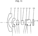
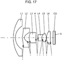
- FIGS. 1 , 3 , 5 , 7 , 9 , 11 , 13 , 15 , and 17 are lens arrangement diagrams showing fixed focal length lens systems according to first to ninth exemplary embodiments, respectively.
- an asterisk "*" attached to a certain surface shows that the surface is aspherical.
- the straight line drawn on the rightmost side of each drawing represents a position of image plane S, and parallel plate CG is provided on an object side of image plane S. Note that an aspect ratio of each drawing is 1.
- Two lenses adjacent to and separate from each other are a lens on an object side and a lens on an image side that face each other, and a distance of air put between an image-side surface of the object-side lens and an object-side surface of the image-side lens is hereinafter referred to as an air lens.
- FIG. 1 shows a fixed focal length lens system according to a first exemplary embodiment.
- the fixed focal length lens system includes, in order from an object side to an image side, first lens element L1 having negative power, second lens element L2 having negative power, third lens element L3 having positive power, aperture diaphragm A, fourth lens element L4 having positive power, fifth lens element L5 having negative power, sixth lens element L6 having positive power, and parallel plate CG.
- First lens element L1 is a meniscus lens having a convex surface on the object side.
- Second lens element L2 is a meniscus lens having a convex surface on the object side.
- Second lens element L2 has an aspherical shape on each of the convex surface on the object side and a concave surface on the image side.
- Third lens element L3 is a meniscus lens having a convex surface on the image side.
- Third lens element L3 has an aspherical shape on each of a concave surface on the object side and the convex surface on the image side.
- Fourth lens element L4 is a biconvex lens made of glass.
- Fifth lens element L5 is a biconcave lens.
- Fifth lens element L5 has an aspherical shape on each of concave surfaces on the object side and the image side.
- Sixth lens element L6 is a biconvex lens. Sixth lens element L6 has an aspherical shape on each of convex surfaces on the object side and the image side.
- Fifth lens element L5 and sixth lens element L6 are cemented to each other with an agent such as an adhesive to make up a cemented lens.
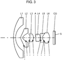
- FIG. 3 shows a fixed focal length lens system according to a second exemplary embodiment.
- the fixed focal length lens system includes, in order from an object side to an image side, first lens element L1 having negative power, second lens element L2 having negative power, third lens element L3 having positive power, aperture diaphragm A, fourth lens element L4 having positive power, fifth lens element L5 having negative power, sixth lens element L6 having positive power, and parallel plate CG.
- First lens element L1 is a meniscus lens having a convex surface on the object side.
- Second lens element L2 is a meniscus lens having a convex surface on the object side.
- Second lens element L2 has an aspherical shape on each of the convex surface on the object side and a concave surface on the image side.
- Third lens element L3 is a meniscus lens having a convex surface on the image side.
- Third lens element L3 has an aspherical shape on each of a concave surface on the object side and the convex surface on the image side.
- Fourth lens element L4 is a biconvex lens made of glass.
- Fifth lens element L5 is a biconcave lens.
- Fifth lens element L5 has an aspherical shape on each of concave surfaces on the object side and the image side.
- Sixth lens element L6 is a biconvex lens. Sixth lens element L6 has an aspherical shape on each of convex surfaces on the object side and the image side.
- Fifth lens element L5 and sixth lens element L6 are cemented to each other with an agent such as an adhesive to make up a cemented lens.
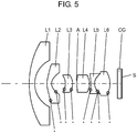
- FIG. 5 shows a fixed focal length lens system according to a third exemplary embodiment.
- the fixed focal length lens system includes, in order from an object side to an image side, first lens element L1 having negative power, second lens element L2 having negative power, third lens element L3 having positive power, aperture diaphragm A, fourth lens element L4 having positive power, fifth lens element L5 having negative power, sixth lens element L6 having positive power, and parallel plate CG.
- First lens element L1 is a meniscus lens having a convex surface on the object side.
- Second lens element L2 is a meniscus lens having a convex surface on the object side.
- Second lens element L2 has an aspherical shape on each of the convex surface on the object side and a concave surface on the image side.
- Third lens element L3 is a meniscus lens having a convex surface on the image side.
- Third lens element L3 has an aspherical shape on each of a concave surface on the object side and the convex surface on the image side.
- Fourth lens element L4 is a biconvex lens made of glass.
- Fifth lens element L5 is a biconcave lens.
- Fifth lens element L5 has an aspherical shape on each of concave surfaces on the object side and the image side.
- Sixth lens element L6 is a biconvex lens. Sixth lens element L6 has an aspherical shape on each of convex surfaces on the object side and the image side.
- Fifth lens element L5 and sixth lens element L6 are cemented to each other with an agent such as an adhesive to make up a cemented lens.
- FIG. 7 shows a fixed focal length lens system according to a fourth exemplary embodiment.
- the fixed focal length lens system includes, in order from an object side to an image side, first lens element L1 having negative power, second lens element L2 having negative power, third lens element L3 having positive power, aperture diaphragm A, fourth lens element L4 having positive power, fifth lens element L5 having negative power, sixth lens element L6 having positive power, and parallel plate CG.
- First lens element L1 is a meniscus lens having a convex surface on the object side.
- Second lens element L2 is a meniscus lens having a convex surface on the object side.
- Second lens element L2 has an aspherical shape on each of the convex surface on the object side and a concave surface on the image side.
- Third lens element L3 is a meniscus lens having a convex surface on the image side.
- Third lens element L3 has an aspherical shape on each of a concave surface on the object side and the convex surface on the image side.
- Fourth lens element L4 is a biconvex lens made of glass.
- Fifth lens element L5 is a biconcave lens.
- Fifth lens element L5 has an aspherical shape on each of concave surfaces on the object side and the image side.
- Sixth lens element L6 is a biconvex lens. Sixth lens element L6 has an aspherical shape on each of convex surfaces on the object side and the image side.
- Fifth lens element L5 and sixth lens element L6 are cemented to each other with an agent such as an adhesive to make up a cemented lens.
- FIG. 9 shows a fixed focal length lens system according to a fifth exemplary embodiment.
- the fixed focal length lens system includes, in order from an object side to an image side, first lens element L1 having negative power, second lens element L2 having negative power, third lens element L3 having positive power, aperture diaphragm A, fourth lens element L4 having positive power, fifth lens element L5 having negative power, sixth lens element L6 having positive power, and parallel plate CG.
- First lens element L1 is a meniscus lens having a convex surface on the object side.
- Second lens element L2 is a meniscus lens having a convex surface on the object side.
- Second lens element L2 has an aspherical shape on each of the convex surface on the object side and a concave surface on the image side.
- Third lens element L3 is a meniscus lens having a convex surface on the image side.
- Third lens element L3 has an aspherical shape on each of a concave surface on the object side and the convex surface on the image side.
- Fourth lens element L4 is a biconvex lens made of glass.
- Fifth lens element L5 is a meniscus lens having a convex surface on the object side.
- Fifth lens element L5 has an aspherical shape on each of the convex surface on the object side and a concave surface on the image side.
- Sixth lens element L6 is a biconvex lens.
- Sixth lens element L6 has an aspherical shape on each of convex surfaces on the object side and the image side.
- Fifth lens element L5 and sixth lens element L6 are cemented to each other with an agent such as an adhesive to make up a cemented lens.
- FIG. 11 shows a fixed focal length lens system according to a sixth exemplary embodiment.
- the fixed focal length lens system includes, in order from an object side to an image side, first lens element L1 having negative power, second lens element L2 having negative power, third lens element L3 having positive power, aperture diaphragm A, fourth lens element L4 having positive power, fifth lens element L5 having negative power, sixth lens element L6 having positive power, and parallel plate CG.
- First lens element L1 is a meniscus lens having a convex surface on the object side.
- Second lens element L2 is a meniscus lens having a convex surface on the object side.
- Second lens element L2 has an aspherical shape on each of the convex surface on the object side and a concave surface on the image side.
- Third lens element L3 is a meniscus lens having a convex surface on the image side.
- Third lens element L3 has an aspherical shape on each of a concave surface on the object side and the convex surface on the image side.
- Fourth lens element L4 is a biconvex lens made of glass.
- Fifth lens element L5 is a meniscus lens having a convex surface on the object side.
- Fifth lens element L5 has an aspherical shape on each of the convex surface on the object side and a concave surface on the image side.
- Sixth lens element L6 is a biconvex lens.
- Sixth lens element L6 has an aspherical shape on each of convex surfaces on the object side and the image side.
- Fifth lens element L5 and sixth lens element L6 are cemented to each other with an agent such as an adhesive to make up a cemented lens.
- FIG. 13 shows a fixed focal length lens system according to a seventh exemplary embodiment.
- the fixed focal length lens system includes, in order from an object side to an image side, first lens element L1 having negative power, second lens element L2 having negative power, third lens element L3 having positive power, aperture diaphragm A, fourth lens element L4 having positive power, fifth lens element L5 having negative power, sixth lens element L6 having positive power, and parallel plate CG.
- First lens element L1 is a meniscus lens having a convex surface on the object side.
- Second lens element L2 is a meniscus lens made of glass, having a convex surface on the object side.
- Second lens element L2 has an aspherical shape on each of the convex surface on the object side and a concave surface on the image side.
- Third lens element L3 is a meniscus lens made of glass, having a convex surface on the image side. Third lens element L3 has an aspherical shape on each of a concave surface on the object side and the convex surface on the image side.
- Fourth lens element L4 is a biconvex lens made of glass.
- Fifth lens element L5 is a biconcave lens made of glass.
- Fifth lens element L5 has an aspherical shape on each of concave surfaces on the object side and the image side.
- Sixth lens element L6 is a biconvex lens made of glass. Sixth lens element L6 has an aspherical shape on each of convex surfaces on the object side and the image side.
- Fifth lens element L5 and sixth lens element L6 are cemented to each other with an agent such as an adhesive to make up a cemented lens.
- FIG. 15 shows a fixed focal length lens system according to an eighth exemplary embodiment.
- the fixed focal length lens system includes, in order from an object side to an image side, first lens element L1 having negative power, second lens element L2 having negative power, third lens element L3 having positive power, aperture diaphragm A, fourth lens element L4 having negative power, fifth lens element L5 having positive power, sixth lens element L6 having positive power, and parallel plate CG.
- First lens element L1 is a meniscus lens having a convex surface on the object side.
- Second lens element L2 is a meniscus lens having a convex surface on the object side.
- Second lens element L2 has an aspherical shape on each of the convex surface on the object side and a concave surface on the image side.
- Third lens element L3 is a biconvex lens. Third lens element L3 has an aspherical shape on each of convex surfaces on the object side and the image side.
- Fourth lens element L4 is a meniscus lens having a convex surface on the object side. Fourth lens element L4 has an aspherical shape on a concave surface on the image side.
- Fifth lens element L5 is a biconvex lens.
- Fifth lens element L5 has an aspherical shape on each of convex surfaces on the object side and the image side.
- Sixth lens element L6 is a biconvex lens made of glass. Sixth lens element L6 has an aspherical shape on each of convex surfaces on the object side and the image side.
- Fourth lens element L4 and fifth lens element L5 are cemented to each other with an agent such as an adhesive to make up a cemented lens.
- FIG. 17 shows a fixed focal length lens system according to a ninth exemplary embodiment.
- the fixed focal length lens system includes, in order from an object side to an image side, first lens element L1 having negative power, second lens element L2 having negative power, third lens element L3 having positive power, aperture diaphragm A, fourth lens element L4 having negative power, fifth lens element L5 having positive power, sixth lens element L6 having positive power, and parallel plate CG.
- First lens element L1 is a meniscus lens having a convex surface on the object side.
- Second lens element L2 is a meniscus lens having a convex surface on the object side.
- Second lens element L2 has an aspherical shape on each of the convex surface on the object side and a concave surface on the image side.
- Third lens element L3 is a biconvex lens. Third lens element L3 has an aspherical shape on each of convex surfaces on the object side and the image side.
- Fourth lens element L4 is a meniscus lens made of glass, having a convex surface on the object side. Fourth lens element L4 has an aspherical shape on a concave surface on the image side.
- Fifth lens element L5 is a biconvex lens made of glass.
- Fifth lens element L5 has an aspherical shape on each of concave surfaces on the object side and the image side.
- Sixth lens element L6 is a biconvex lens made of glass. Sixth lens element L6 has an aspherical shape on each of convex surfaces on the object side and the image side.
- Fourth lens element L4 and fifth lens element L5 are cemented to each other with an agent such as an adhesive to make up a cemented lens.
- a plurality of beneficial conditions is set for the fixed focal length lens systems of the exemplary embodiments, and a configuration of a fixed focal length lens system satisfying all of the conditions is the most effective.
- a fixed focal length lens system such as the fixed focal length lens systems of the first to the ninth exemplary embodiments, includes, in order from an object side to an image side, in order from an object side to an image side, first lens element L1 having negative power, second lens element L2 having negative power, third lens element L3 having positive power, fourth lens element L4 having power, fifth lens element L5 having power, and sixth lens element L6 having positive power. At least one of second to sixth lens elements L2 to L6 is made of glass.
- this lens configuration is referred to as a basic configuration of an exemplary embodiment.
- a fixed focal length lens system having the basic configuration desirably satisfies condition (1), for example, shown below.
- condition (1) for example, shown below.
- L1R2 is a radius of curvature of an image-side surface of first lens element L1
- L2R1 is a radius of curvature of an object-side surface of second lens element L2.
- Condition (1) is a condition for specifying a shape factor of an air lens put between first lens element L1 and the second lens element. Falling below a lower limit of condition (1) or exceeding an upper limit of conditional expression (1) means an increase in spherical aberration of light rays passing close to an optical axis of the fixed focal length lens system having the basic configuration, causing a decrease in resolution.
- fourth lens element L4 has positive power and fifth lens element L5 has negative power.
- a fixed focal length lens system having the basic configuration desirably satisfies condition (2) shown below. 6.7 ⁇ f 3 / L 3 ⁇ th ⁇ 30 where f3 is a focal distance of third lens element L3, and L3th is a thickness of third lens element L3 in an optical axis direction.
- Condition (2) is a condition for specifying a ratio of the focal distance of third lens element L3 to the thickness of third lens element L3 in the optical axis direction. If this ratio falls below a lower limit of condition (2) or exceeds an upper limit of conditional expression (2), the lens system cannot satisfactorily correct aberrations, in particular an axial chromatic aberration, and thus causes a decrease in resolution.
- a fixed focal length lens system having the basic configuration desirably satisfies condition (3) shown below.
- condition (3) shown below.
- L4R2 is a radius of curvature of an image-side surface of fourth lens element L4
- L5R1 is a radius of curvature of an object-side surface of fifth lens element L5.
- Condition (3) is a condition for specifying a shape factor of an air lens put between fourth lens element L4 and fifth lens element L5. If this shape factor falls below a lower limit of condition (3) or exceeds an upper limit of conditional expression (3), the lens system cannot satisfactorily correct aberrations, in particular astigmatism, and thus causes a decrease in resolution.
- a fixed focal length lens system having the basic configuration desirably satisfies condition (4) shown below. 8.8 ⁇ L 3 R 1 + L 3 R 2 / L 3 R 1 ⁇ L 3 R 2 ⁇ 130 where L3R1 is a radius of curvature of an image-side surface of third lens element L3, and L3R2 is a radius of curvature of an object-side surface of third lens element L3.
- Condition (4) is a condition for specifying a shape factor of third lens element L3. If this shape factor falls below a lower limit of condition (4) or exceeds an upper limit of conditional expression (4), the lens system cannot satisfactorily correct aberrations, in particular a coma aberration, and thus causes a decrease in resolution.
- a fixed focal length lens system having the basic configuration desirably satisfies condition (5) shown below. 0.78 ⁇ L 5 R 1 + L 5 R 2 / L 5 R 1 ⁇ L 5 R 2 ⁇ 2.5 where L5R1 is a radius of curvature of an image-side surface of fifth lens element L5, and L5R2 is a radius of curvature of an object-side surface of fifth lens element L5.
- Condition (5) is a condition for specifying a shape factor of fifth lens element L5. If this shape factor falls below a lower limit of condition (5) or exceeds an upper limit of conditional expression (5), the lens system cannot satisfactorily correct aberrations, in particular astigmatism, and thus causes a decrease in resolution.
- a fixed focal length lens system having the basic configuration desirably satisfies condition (6) shown below.
- Condition (6) is a condition for specifying the Abbe number of sixth lens element L6. Falling below a lower limit of condition (6) means that the Abbe number of sixth lens element L6 is too small. As a result, the lens system cannot satisfactorily correct aberrations, in particular a chromatic aberration of magnification, and thus causes a decrease in resolution.
- a camera including the fixed focal length lens system according to the first exemplary embodiment will be described, with an on-vehicle camera taken as an example.
- the on-vehicle camera may include any one of the fixed focal length lens systems according to the second to ninth exemplary embodiments instead of the fixed focal length lens system according to the first exemplary embodiment.
- FIG. 19 is a schematic diagram of an on-vehicle camera equipped with the fixed focal length lens system according to the first exemplary embodiment.
- On-vehicle camera 100 includes fixed focal length lens system 201 to form an optical image of an object and imaging device 202 to convert the optical image formed by fixed focal length lens system 201 into an electrical image signal.
- Imaging device 202 is disposed at a position of image plane S in the fixed focal length lens system according to the first exemplary embodiment.
- FIG. 20 is a schematic diagram of vehicle 500 equipped with on-vehicle camera 100 at a rear position.
- On-vehicle camera 100 is installed in vehicle 500 and is used as a sensing camera or a view camera. An image taken by the sensing camera is used to check an inter-vehicle distance to another vehicle and the like. An image taken by the view camera is displayed on a monitor in the vehicle to allow the driver to check an area surrounding the vehicle such as ahead of the vehicle, behind the vehicle, and on a side of the vehicle.
- An image signal acquired by imaging device 202 is, for example, displayed on a device such as display device 401 or display device 402 located in a front of a cabin of vehicle 500.
- the image signal is, for example, stored as image data in a memory.
- Display device 401 is an electronic room mirror, for example.
- Display device 402 is a display device in a navigation system or on a front panel, for example.
- vehicle 500 can display an image of an area behind the vehicle on the device such as display device 401 or display device 402 via on-vehicle camera 100 including fixed focal length lens system 201. This configuration enables an occupant such as the driver to view an area behind vehicle 500.
- the fixed focal length lens system of the present disclosure is effective as a lens system for a view camera but can be used also as a lens system for a sensing camera.
- the tenth exemplary embodiment has been described above as an example of the technique disclosed in the present application.
- the technique of the present disclosure can be applied not only to the above exemplary embodiments but also to exemplary embodiments in which modification, replacement, addition, or omission is appropriately made.
- a lens element having substantially no power may be added as appropriate to any of the fixed focal length lens systems according to the first to ninth exemplary embodiments.
- the aspherical shape on the lens elements included in the fixed focal length lens systems of the first to ninth exemplary embodiments may be formed by a process other than polishing and molding.
- the lens element may be, for example, what is called a replicated lens (a hybrid lens) in which an aspherical coating is formed on a surface of a spherical lens.
- the fixed focal length lens system according to any of the first to ninth exemplary embodiments in the present disclosure is applied to the on-vehicle camera as a sensing camera or a view camera; however, it is a matter of course that the fixed focal length lens system of the present disclosure can be applied to a surveillance camera in a surveillance system, a web camera, and other cameras.
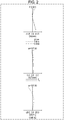
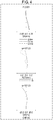
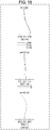
- FIGS. 2 , 4 , 6 , 8 , 10 , 12 , 14 , 16 , and 18 are longitudinal aberration diagrams of respective fixed focal length lens systems in the infinity focusing state according to the first to ninth numerical examples.
- Each longitudinal aberration diagram shows, in order from the top, a spherical aberration (SA (mm)), an astigmatism (AST (mm)), and a distortion (DIS (%)).
- SA spherical aberration
- AST mm
- DIS distortion
- the vertical axis represents an F number (indicated by F in the drawing).
- the solid line, the short broken line, and the long broken line represent characteristics for a d-line, an F-line, and a C-line, respectively.
- the vertical axis represents an image height.
- the solid line and the broken line represent characteristics for a sagittal plane (indicated by s in the drawing) and a meridional plane (indicated by m in the drawing), respectively.
- w represents a half angle of view.
- the vertical axis represents an image height
- w represents a half angle of view.
- the fixed focal length lens system according to the first numerical example corresponds to the first exemplary embodiment shown in FIG. 1 .
- Table 2 Surface data
- Surface number r d nd vd Effective diameter Object surface ⁇ 1 13.89440 0.90000 1.80420 46.5 7.201 2 4.92320 1.61040 3* 2.46160 0.80000 1.53345 55.6 3.696 4* 0.96050 2.84200 5* -3.00920 1.40000 1.65521 21.1 1.373 6* -2.46880 0.55570 5.171 7(diaphragm) ⁇ 0.36230 0.983 8 6.65070 1.80000 1.61800 63.4 9 -3.14270 0.20000 10* -28.44780 0.70000 1.65521 21.1 11* 1.99800 0.00500 1.56732 42.8 5.569 12* 1.99800 2.66000 1.53345 55.6 5.569 13* -3.18430 1.33960 2.071 14 ⁇ 0.70000 1.51680 64.2 15 ⁇ 0.12500 16 ⁇ BF Image surface
- the fixed focal length lens system according to the second numerical example corresponds to the second exemplary embodiment shown in FIG. 3 .
- Table 6 Surface data
- Surface number r d nd vd Effective diameter Object surface ⁇ 1 14.75500 0.80080 1.80420 46.5 8.001 2 6.01930 1.95300 3* 1.23520 0.80480 1.53345 55.6 3.689 4* 0.57700 2.83160 5* -3.01000 1.30000 1.65521 21.1 1.550 6* -2.43030 0.72540 4.914 7(diaphragm) ⁇ 0.16350 0.916 8 8.55950 1.68990 1.61800 63.4 9 -3.00160 0.20600 10* -45.08580 0.70960 1.65521 21.1 11* 1.99660 0.00500 1.56732 42.8 5.559 12* 1.99660 2.75300 1.53345 55.6 5.559 13* -2.56440 1.33450 2.074 14 ⁇ 0.70000 1.51680 64.2 15 ⁇ 0.12500 16 ⁇ BF Image surface ⁇
- the fixed focal length lens system according to the third numerical example corresponds to the third exemplary embodiment shown in FIG. 5 .
- Table 10 Surface data
- Surface number r d nd vd Effective diameter Object surface ⁇ 1 14.21000 0.99920 1.80420 46.5 7.271 2 4.47260 2.18760 3* 3.91560 0.80470 1.53345 55.6 3.406 4* 1.20580 2.47730 5* -2.87230 1.30000 1.65521 21.1 1.405 6* -2.37400 0.73290 5.660 7(diaphragm) ⁇ 0.04390 1.017 8 6.31670 2.22050 1.61800 63.4 9 -3.16880 0.23650 10* -24.61120 0.70660 1.65521 21.1 11* 2.03020 0.00500 1.56732 42.8 5.580 12* 2.03020 2.77410 1.53345 55.6 5.580 13* -3.09210 1.33200 2.070 14 ⁇ 0.70000 1.51680 64.2 15 ⁇ 0.12500 16 ⁇
- the fixed focal length lens system according to the fourth numerical example corresponds to the fourth exemplary embodiment shown in FIG. 7 .
- Table 14 Surface data
- Surface number r d nd vd Effective diameter Object surface ⁇ 1 14.42570 0.79310 1.77250 49.6 7.401 2 4.99800 2.04960 3* 2.77670 0.66540 1.53345 55.6 3.705 4* 1.04170 2.75830 5* -3.06080 1.40000 1.65521 21.1 1.591 6* -3.01250 1.07210 2.227 7(diaphragm) ⁇ 0.12180 1.064 8 4.28130 2.20770 1.61800 63.4 9 -3.86760 0.25270 10* 846.4 7040 0.70000 1.65521 21.1 0.636 11* 1.89620 0.00500 1.56732 42.8 5.607 12* 1.89620 2.71190 1.53345 55.6 5.607 13* -3.45270 1.35180 2.072 14 ⁇ 0.70000 1.51680 64.2 15 ⁇ 0.12500 16
- the fixed focal length lens system according to the fifth numerical example corresponds to the fifth exemplary embodiment shown in FIG. 9 .
- Table 18 (Surface data) Surface number r d nd vd Effective diameter Object surface ⁇ 1 14.95760 0.82730 1.80420 46.5 7.601 2 4.77670 2.25240 3* 2.65370 0.75000 1.53345 55.6 3.354 4* 1.02660 2.59820 5* -3.18440 1.49380 1.65521 21.1 1.544 6* -3.06330 1.18560 2.832 7(diaphragm) ⁇ 0.01450 1.080 8 5.29340 2.30090 1.61800 63.4 9 -6.99560 0.62310 10* 6.85710 0.70000 1.65521 21.1 1.994 11* 1.93050 0.00500 1.56732 42.8 12* 1.93050 3.24410 1.53345 55.6 13* -3.21920 1.28550 2.241 14 ⁇ 0.70000 1.51680 64.2 15 ⁇ 0.12500 16 ⁇ BF Image
- the fixed focal length lens system according to the sixth numerical example corresponds to the sixth exemplary embodiment shown in FIG. 11 .
- [Table 22] Surface number r d nd vd Effective diameter Object surface ⁇ 1 14.99940 0.80000 1.80420 46.5 7.604 2 4.73720 2.28010 3* 2.63180 0.75000 1.53345 55.6 3.515 4* 1.00490 3.01010 2.227 5* -3.54580 1.40000 1.65521 21.1 1.583 6* -3.43750 1.37260 2.645 7(diaphragm) ⁇ 0.15360 1.144 8 3.72950 1.64080 1.61800 63.4 9 -92301.49890 1.14880 10* 4.93500 0.70000 1.65521 21.1 1.810 11* 2.03970 0.00500 1.56732 42.8 12* 2.03970 3.55350 1.53345 55.6 13* -3.39540 1.20730 2.404 14 ⁇ 0.70000 1.51680 64.2 15 ⁇ 0.12500 16 ⁇ BF Image surface
- the fixed focal length lens system according to the seventh numerical example corresponds to the seventh exemplary embodiment shown in FIG. 13 .
- [Table 26] Surface number r d nd vd Effective diameter Object surface ⁇ 1 13.13320 0.80000 1.80420 46.5 7.201 2 4.93460 2.13620 3* 3.03810 0.70000 1.58913 61.3 3.517 4* 1.11790 2.59370 5* -3.19010 1.49710 1.68893 31.1 1.605 6* -2.44560 0.89710 2.549 7(diaphragm) ⁇ 0.33050 0.998 8 7.79100 1.82550 1.61800 63.4 9 -3.27050 0.20440 10* -38.20810 0.70000 1.68893 31.1 11* 1.86030 0.00500 1.56732 42.8 5.615 12* 1.86030 2.73240 1.56873 63.2 5.615 13* -3.35970 1.36850 2.074 14 ⁇ 0.70000 1.51680 64.2 15 ⁇ 0.12500 16 ⁇
- the fixed focal length lens system according to the eighth numerical example corresponds to the eighth exemplary embodiment shown in FIG. 15 .
- Table 30 (Surface data) Surface number r d nd vd Effective diameter Object surface ⁇ 1 12.74210 0.78730 1.80420 46.5 7.193 2 4.89140 2.83110 3* 4.77600 0.75280 1.53345 55.6 5.420 4* 1.00900 1.85630 1.765 5* 6.75390 2.53160 1.63970 23.5 1.861 6* -4.59790 0.06300 7(diaphragm) ⁇ 0.65090 0.900 8* 4.32780 0.99990 1.63970 23.5 1.092 9* 0.95680 0.00500 1.56732 42.8 1.982 10* 0.95680 1.94890 1.53345 55.6 1.982 11* -8.83330 0.10010 1.759 12* 3.44770 1.76190 1.55332 71.7 3.115 13* -7.98430 1.37610 2.400 14 ⁇ 0.75000 1.51680 64.2 15
- the fixed focal length lens system according to the ninth numerical example corresponds to the ninth exemplary embodiment shown in FIG. 17 .
- Table 34 (Surface data) Surface number r d nd vd Effective diameter Object surface ⁇ 1 13.25130 0.80000 1.83481 42.7 7.201 2 5.22020 2.76940 3* 4.85000 0.75000 1.53345 55.6 8.785 4* 1.01090 1.90910 2.089 5* 4.90360 2.67070 1.63970 23.5 6* -14.26890 0.51570 1.515 7(diaphragm) ⁇ 0.23350 0.826 8* 3.42740 1.50000 1.82115 24.1 0.861 9* 1.12080 0.00500 1.56732 42.8 1.818 10* 1.12080 1.77410 1.61881 63.9 1.818 11* -3.69120 0.10000 1.598 12* 3.44240 1.50510 1.55332 71.7 4.279 13* 184.16160 1.05830 2.486 14 ⁇ 0.75000 1.51680 64.2 15
- constituent elements described in the accompanying drawings and the detailed description may include not only the constituent elements essential for solving the problem but also constituent elements that are not essential for solving the problem in order to illustrate the technique. It should not be therefore determined that the unessential constituent elements in the accompanying drawings and the detailed description are essential only based on the fact that these constituent elements are included in the drawings and the description.
- the present disclosure can be applied to fixed focal length lens systems for use in devices such as on-vehicle cameras, surveillance cameras, and web cameras.
- the present disclosure is beneficial for a fixed focal length lens system used in a camera such as an on-vehicle camera that is required to provide improved picture quality.
Landscapes
- Physics & Mathematics (AREA)
- General Physics & Mathematics (AREA)
- Optics & Photonics (AREA)
- Engineering & Computer Science (AREA)
- Multimedia (AREA)
- Signal Processing (AREA)
- Lenses (AREA)
Applications Claiming Priority (2)
| Application Number | Priority Date | Filing Date | Title |
|---|---|---|---|
| JP2017008505 | 2017-01-20 | ||
| PCT/JP2017/046902 WO2018135269A1 (ja) | 2017-01-20 | 2017-12-27 | 単焦点レンズ系、および、カメラ |
Publications (2)
| Publication Number | Publication Date |
|---|---|
| EP3572859A1 true EP3572859A1 (de) | 2019-11-27 |
| EP3572859A4 EP3572859A4 (de) | 2020-01-22 |
Family
ID=62907909
Family Applications (1)
| Application Number | Title | Priority Date | Filing Date |
|---|---|---|---|
| EP17892933.7A Pending EP3572859A4 (de) | 2017-01-20 | 2017-12-27 | Linsensystem mit fester brennweite und kamera |
Country Status (5)
| Country | Link |
|---|---|
| US (1) | US11467374B2 (de) |
| EP (1) | EP3572859A4 (de) |
| JP (1) | JP6837194B2 (de) |
| CN (1) | CN110178068B (de) |
| WO (1) | WO2018135269A1 (de) |
Families Citing this family (17)
| Publication number | Priority date | Publication date | Assignee | Title |
|---|---|---|---|---|
| TWI641865B (zh) | 2017-09-27 | 2018-11-21 | 大立光電股份有限公司 | 光學成像鏡組、取像裝置及電子裝置 |
| CN109709658B (zh) * | 2017-10-25 | 2021-02-05 | 信泰光学(深圳)有限公司 | 摄像镜头 |
| TWI670516B (zh) * | 2018-06-13 | 2019-09-01 | 大立光電股份有限公司 | 攝影光學鏡頭、取像裝置及電子裝置 |
| CN109407279B (zh) * | 2018-12-12 | 2021-09-14 | 江西联创电子有限公司 | 广角镜头及成像设备 |
| CN111367047B (zh) * | 2020-03-31 | 2024-06-18 | 玉晶光电(厦门)有限公司 | 光学成像镜头 |
| US11391925B2 (en) | 2020-04-26 | 2022-07-19 | Young Optics Inc. | Optical lens |
| CN113625419B (zh) * | 2020-05-07 | 2023-11-03 | 宁波舜宇车载光学技术有限公司 | 光学镜头及包括该光学镜头的成像设备 |
| DE102020115494B3 (de) * | 2020-05-19 | 2021-04-22 | Jenoptik Optical Systems Gmbh | Objektiv, Verwendung eınes Objektivs, Messsystem mit einem Objektiv sowie Verwendung einer biasphärischen Kunststofflinse in einem Objektiv |
| TWI718066B (zh) * | 2020-05-29 | 2021-02-01 | 紘立光電股份有限公司 | 光學攝像透鏡組、成像裝置及電子裝置 |
| KR20220093930A (ko) * | 2020-12-28 | 2022-07-05 | 엘지이노텍 주식회사 | 차량용 광학계 및 카메라 모듈 |
| CN116547581A (zh) * | 2021-06-09 | 2023-08-04 | 奥林巴斯医疗株式会社 | 物镜光学系统、摄像装置以及内窥镜 |
| TWI784660B (zh) * | 2021-08-09 | 2022-11-21 | 今國光學工業股份有限公司 | 六片式光學鏡頭模組 |
| JP2023075469A (ja) * | 2021-11-19 | 2023-05-31 | ニデックインスツルメンツ株式会社 | 広角レンズ |
| JP2023075468A (ja) * | 2021-11-19 | 2023-05-31 | ニデックインスツルメンツ株式会社 | 広角レンズ |
| JP7213438B1 (ja) | 2022-04-28 | 2023-01-27 | パナソニックIpマネジメント株式会社 | 撮像レンズ系、および、カメラ |
| CN115343827B (zh) * | 2022-07-14 | 2024-12-13 | 福建福光天瞳光学有限公司 | 一种超大广角光学镜头及其成像方法 |
| CN118671944B (zh) * | 2023-03-16 | 2026-03-10 | 宁波舜宇车载光学技术有限公司 | 光学镜头和电子设备 |
Family Cites Families (29)
| Publication number | Priority date | Publication date | Assignee | Title |
|---|---|---|---|---|
| JPS5127845A (ja) | 1974-09-03 | 1976-03-09 | Koki Kk | Handazukesochi |
| JPS51129224A (en) * | 1975-05-02 | 1976-11-10 | Nippon Kogaku Kk <Nikon> | Wide angle lens |
| JPS59165014A (ja) * | 1983-03-10 | 1984-09-18 | Asahi Optical Co Ltd | バツクフオ−カスの長い高解像力集光レンズ光学系 |
| JPH01210914A (ja) * | 1988-02-19 | 1989-08-24 | Olympus Optical Co Ltd | 変倍レンズ |
| US4999007A (en) | 1988-01-28 | 1991-03-12 | Olympus Optical Co., Ltd. | Vari-focal lens system |
| JPH02220015A (ja) * | 1989-02-22 | 1990-09-03 | Matsushita Electric Ind Co Ltd | 精密投影光学系 |
| DE68916451T2 (de) | 1988-03-11 | 1994-11-17 | Matsushita Electric Ind Co Ltd | Optisches Projektionssystem. |
| JP2808815B2 (ja) * | 1990-04-19 | 1998-10-08 | 株式会社ニコン | 内部合焦式望遠ズームレンズ |
| JPH08160296A (ja) * | 1994-12-01 | 1996-06-21 | Olympus Optical Co Ltd | 撮像系 |
| US5841590A (en) * | 1996-08-27 | 1998-11-24 | Nikon Corporation | Aberration controllable optical system |
| JP2002055277A (ja) | 2000-08-11 | 2002-02-20 | Nikon Corp | リレー結像光学系、および該光学系を備えた照明光学装置並びに露光装置 |
| JP4055599B2 (ja) * | 2003-02-13 | 2008-03-05 | コニカミノルタオプト株式会社 | 撮像レンズ装置およびそれを備えた電子機器 |
| JP4739810B2 (ja) * | 2005-05-02 | 2011-08-03 | リコー光学株式会社 | 投射用レンズおよびプロジェクタ装置 |
| JP2007164079A (ja) * | 2005-12-16 | 2007-06-28 | Elmo Co Ltd | 魚眼レンズユニット |
| CN201314970Y (zh) * | 2008-05-27 | 2009-09-23 | 富士能株式会社 | 摄像透镜及使用此摄像透镜的摄像装置 |
| JP5102110B2 (ja) | 2008-05-27 | 2012-12-19 | 富士フイルム株式会社 | 撮像レンズおよびこの撮像レンズを用いた撮像装置 |
| US7957074B2 (en) | 2008-05-27 | 2011-06-07 | Fujinon Corporation | Imaging lens system and imaging apparatus using the imaging lens system |
| JP2009300797A (ja) * | 2008-06-13 | 2009-12-24 | Fujinon Corp | 撮像レンズ及びカプセル型内視鏡 |
| JP2010160198A (ja) * | 2009-01-06 | 2010-07-22 | Sony Corp | ズームレンズ及び撮像装置 |
| JP5468966B2 (ja) * | 2010-04-02 | 2014-04-09 | 富士フイルム株式会社 | 投写レンズおよびこれを用いた投写型表示装置 |
| WO2013046566A1 (ja) * | 2011-09-29 | 2013-04-04 | 富士フイルム株式会社 | 撮像レンズおよび撮像装置 |
| TWI449944B (zh) * | 2012-07-24 | 2014-08-21 | Largan Precision Co Ltd | 廣視角光學鏡頭組 |
| JP2014134563A (ja) * | 2013-01-08 | 2014-07-24 | Ricoh Co Ltd | 結像レンズ、画像読取装置及び画像形成装置 |
| TWI490535B (zh) * | 2013-09-16 | 2015-07-01 | Kinko Optical Co Ltd | 五片式廣角鏡頭 |
| JP2015190999A (ja) | 2014-03-27 | 2015-11-02 | 株式会社タムロン | 結像光学系 |
| CN104330868B (zh) * | 2014-07-29 | 2017-05-10 | 玉晶光电(厦门)有限公司 | 光学成像镜头及应用该光学成像镜头的电子装置 |
| JP6385214B2 (ja) * | 2014-09-12 | 2018-09-05 | 日本電産サンキョー株式会社 | 広角レンズ |
| TWI572892B (zh) * | 2015-02-26 | 2017-03-01 | 大立光電股份有限公司 | 透鏡系統、取像裝置及電子裝置 |
| CN105866930B (zh) * | 2016-06-21 | 2018-07-06 | 中山联合光电科技股份有限公司 | 一种高清镜头 |
-
2017
- 2017-12-27 WO PCT/JP2017/046902 patent/WO2018135269A1/ja not_active Ceased
- 2017-12-27 CN CN201780083641.XA patent/CN110178068B/zh active Active
- 2017-12-27 EP EP17892933.7A patent/EP3572859A4/de active Pending
- 2017-12-27 JP JP2018563252A patent/JP6837194B2/ja active Active
-
2019
- 2019-06-25 US US16/451,149 patent/US11467374B2/en active Active
Also Published As
| Publication number | Publication date |
|---|---|
| CN110178068B (zh) | 2022-02-01 |
| JPWO2018135269A1 (ja) | 2019-11-07 |
| US20190310442A1 (en) | 2019-10-10 |
| EP3572859A4 (de) | 2020-01-22 |
| US11467374B2 (en) | 2022-10-11 |
| CN110178068A (zh) | 2019-08-27 |
| WO2018135269A1 (ja) | 2018-07-26 |
| JP6837194B2 (ja) | 2021-03-03 |
Similar Documents
| Publication | Publication Date | Title |
|---|---|---|
| US11467374B2 (en) | Fixed focal length lens system and camera | |
| US11385445B2 (en) | Single-focus lens system and camera | |
| EP3070506B1 (de) | Einzelfokus-linsensystem, kamera und kraftfahrzeug | |
| CN106959505B (zh) | 成像透镜及摄像装置 | |
| EP3422070B1 (de) | Zoomobjektivsystem, bildaufnahmevorrichtung mit einem zoomobjektivsystem und fahrzeug mit einer bildaufnahmevorrichtung | |
| CN107015348B (zh) | 成像透镜及摄像装置 | |
| CN105874372B (zh) | 单焦点透镜系统、相机以及机动车 | |
| EP3531181B1 (de) | Bildgebungslinsensystem und kamera | |
| EP1906223A2 (de) | Kompaktes Weitwinkelobjektiv mit drei Einzellinsen | |
| EP3255473A1 (de) | Abbildungslinse und abbildungsvorrichtung | |
| CN107544128B (zh) | 成像透镜及摄像装置 | |
| JP2018136476A (ja) | 撮像レンズおよび撮像装置 | |
| JP2018116076A (ja) | 撮像レンズおよび撮像装置 | |
| EP3457190B1 (de) | Optisches bildgebungssystem | |
| US10168547B2 (en) | Zoom lens system, imaging apparatus, and camera | |
| EP3465314B1 (de) | Optisches abbildungssystem und abbildungsvorrichtung | |
| CN104583833A (zh) | 摄像透镜以及具备该摄像透镜的摄像装置 | |
| EP3650902B1 (de) | Optisches system mit einzelfokus-bildaufnahme sowie bildaufnahmevorrichtung und kamerasystem mit einem optischen einzelfokus-bildaufnahmesystem | |
| JP2018013580A (ja) | 撮像レンズおよび撮像装置 | |
| EP3702823A1 (de) | Zoomobjektivsystem und bildgebungsvorrichtung | |
| US12392992B2 (en) | Imaging optical system and camera | |
| US20230350171A1 (en) | Imaging lens system and camera | |
| US20180074301A1 (en) | Zoom lens system, imaging apparatus and camera | |
| JP6286663B2 (ja) | 広角レンズ系、カメラ |
Legal Events
| Date | Code | Title | Description |
|---|---|---|---|
| STAA | Information on the status of an ep patent application or granted ep patent |
Free format text: STATUS: THE INTERNATIONAL PUBLICATION HAS BEEN MADE |
|
| PUAI | Public reference made under article 153(3) epc to a published international application that has entered the european phase |
Free format text: ORIGINAL CODE: 0009012 |
|
| STAA | Information on the status of an ep patent application or granted ep patent |
Free format text: STATUS: REQUEST FOR EXAMINATION WAS MADE |
|
| 17P | Request for examination filed |
Effective date: 20190718 |
|
| AK | Designated contracting states |
Kind code of ref document: A1 Designated state(s): AL AT BE BG CH CY CZ DE DK EE ES FI FR GB GR HR HU IE IS IT LI LT LU LV MC MK MT NL NO PL PT RO RS SE SI SK SM TR |
|
| AX | Request for extension of the european patent |
Extension state: BA ME |
|
| A4 | Supplementary search report drawn up and despatched |
Effective date: 20191219 |
|
| RIC1 | Information provided on ipc code assigned before grant |
Ipc: G02B 13/00 20060101ALI20191213BHEP Ipc: G02B 13/06 20060101ALI20191213BHEP Ipc: G02B 9/62 20060101ALI20191213BHEP Ipc: G02B 13/04 20060101AFI20191213BHEP |
|
| DAV | Request for validation of the european patent (deleted) | ||
| DAX | Request for extension of the european patent (deleted) | ||
| STAA | Information on the status of an ep patent application or granted ep patent |
Free format text: STATUS: EXAMINATION IS IN PROGRESS |
|
| 17Q | First examination report despatched |
Effective date: 20210709 |
|
| GRAP | Despatch of communication of intention to grant a patent |
Free format text: ORIGINAL CODE: EPIDOSNIGR1 |
|
| STAA | Information on the status of an ep patent application or granted ep patent |
Free format text: STATUS: GRANT OF PATENT IS INTENDED |
|
| INTG | Intention to grant announced |
Effective date: 20260129 |