EP3573194B1 - Elastischer pol, kombiniertes element, hochspannungsanordnung, elektrischer verbinder und batterieladeplatte - Google Patents
Elastischer pol, kombiniertes element, hochspannungsanordnung, elektrischer verbinder und batterieladeplatte Download PDFInfo
- Publication number
- EP3573194B1 EP3573194B1 EP18741039.4A EP18741039A EP3573194B1 EP 3573194 B1 EP3573194 B1 EP 3573194B1 EP 18741039 A EP18741039 A EP 18741039A EP 3573194 B1 EP3573194 B1 EP 3573194B1
- Authority
- EP
- European Patent Office
- Prior art keywords
- pole
- conductive
- contact
- voltage
- spring
- Prior art date
- Legal status (The legal status is an assumption and is not a legal conclusion. Google has not performed a legal analysis and makes no representation as to the accuracy of the status listed.)
- Active
Links
Images





Classifications
-
- H—ELECTRICITY
- H01—ELECTRIC ELEMENTS
- H01R—ELECTRICALLY-CONDUCTIVE CONNECTIONS; STRUCTURAL ASSOCIATIONS OF A PLURALITY OF MUTUALLY-INSULATED ELECTRICAL CONNECTING ELEMENTS; COUPLING DEVICES; CURRENT COLLECTORS
- H01R13/00—Details of coupling devices of the kinds covered by groups H01R12/70 or H01R24/00 - H01R33/00
- H01R13/62—Means for facilitating engagement or disengagement of coupling parts or for holding them in engagement
- H01R13/629—Additional means for facilitating engagement or disengagement of coupling parts, e.g. aligning or guiding means, levers, gas pressure electrical locking indicators, manufacturing tolerances
- H01R13/631—Additional means for facilitating engagement or disengagement of coupling parts, e.g. aligning or guiding means, levers, gas pressure electrical locking indicators, manufacturing tolerances for engagement only
- H01R13/6315—Additional means for facilitating engagement or disengagement of coupling parts, e.g. aligning or guiding means, levers, gas pressure electrical locking indicators, manufacturing tolerances for engagement only allowing relative movement between coupling parts, e.g. floating connection
-
- B—PERFORMING OPERATIONS; TRANSPORTING
- B60—VEHICLES IN GENERAL
- B60L—PROPULSION OF ELECTRICALLY-PROPELLED VEHICLES; SUPPLYING ELECTRIC POWER FOR AUXILIARY EQUIPMENT OF ELECTRICALLY-PROPELLED VEHICLES; ELECTRODYNAMIC BRAKE SYSTEMS FOR VEHICLES IN GENERAL; MAGNETIC SUSPENSION OR LEVITATION FOR VEHICLES; MONITORING OPERATING VARIABLES OF ELECTRICALLY-PROPELLED VEHICLES; ELECTRIC SAFETY DEVICES FOR ELECTRICALLY-PROPELLED VEHICLES
- B60L53/00—Methods of charging batteries, specially adapted for electric vehicles; Charging stations or on-board charging equipment therefor; Exchange of energy storage elements in electric vehicles
- B60L53/10—Methods of charging batteries, specially adapted for electric vehicles; Charging stations or on-board charging equipment therefor; Exchange of energy storage elements in electric vehicles characterised by the energy transfer between the charging station and the vehicle
- B60L53/14—Conductive energy transfer
- B60L53/16—Connectors, e.g. plugs or sockets, specially adapted for charging electric vehicles
-
- B—PERFORMING OPERATIONS; TRANSPORTING
- B60—VEHICLES IN GENERAL
- B60L—PROPULSION OF ELECTRICALLY-PROPELLED VEHICLES; SUPPLYING ELECTRIC POWER FOR AUXILIARY EQUIPMENT OF ELECTRICALLY-PROPELLED VEHICLES; ELECTRODYNAMIC BRAKE SYSTEMS FOR VEHICLES IN GENERAL; MAGNETIC SUSPENSION OR LEVITATION FOR VEHICLES; MONITORING OPERATING VARIABLES OF ELECTRICALLY-PROPELLED VEHICLES; ELECTRIC SAFETY DEVICES FOR ELECTRICALLY-PROPELLED VEHICLES
- B60L53/00—Methods of charging batteries, specially adapted for electric vehicles; Charging stations or on-board charging equipment therefor; Exchange of energy storage elements in electric vehicles
- B60L53/80—Exchanging energy storage elements, e.g. removable batteries
-
- H—ELECTRICITY
- H01—ELECTRIC ELEMENTS
- H01M—PROCESSES OR MEANS, e.g. BATTERIES, FOR THE DIRECT CONVERSION OF CHEMICAL ENERGY INTO ELECTRICAL ENERGY
- H01M50/00—Constructional details or processes of manufacture of the non-active parts of electrochemical cells other than fuel cells, e.g. hybrid cells
- H01M50/20—Mountings; Secondary casings or frames; Racks, modules or packs; Suspension devices; Shock absorbers; Transport or carrying devices; Holders
- H01M50/262—Mountings; Secondary casings or frames; Racks, modules or packs; Suspension devices; Shock absorbers; Transport or carrying devices; Holders with fastening means, e.g. locks
-
- H—ELECTRICITY
- H01—ELECTRIC ELEMENTS
- H01M—PROCESSES OR MEANS, e.g. BATTERIES, FOR THE DIRECT CONVERSION OF CHEMICAL ENERGY INTO ELECTRICAL ENERGY
- H01M50/00—Constructional details or processes of manufacture of the non-active parts of electrochemical cells other than fuel cells, e.g. hybrid cells
- H01M50/20—Mountings; Secondary casings or frames; Racks, modules or packs; Suspension devices; Shock absorbers; Transport or carrying devices; Holders
- H01M50/298—Mountings; Secondary casings or frames; Racks, modules or packs; Suspension devices; Shock absorbers; Transport or carrying devices; Holders characterised by the wiring of battery packs
-
- H—ELECTRICITY
- H01—ELECTRIC ELEMENTS
- H01R—ELECTRICALLY-CONDUCTIVE CONNECTIONS; STRUCTURAL ASSOCIATIONS OF A PLURALITY OF MUTUALLY-INSULATED ELECTRICAL CONNECTING ELEMENTS; COUPLING DEVICES; CURRENT COLLECTORS
- H01R13/00—Details of coupling devices of the kinds covered by groups H01R12/70 or H01R24/00 - H01R33/00
- H01R13/02—Contact members
- H01R13/15—Pins, blades or sockets having separate spring member for producing or increasing contact pressure
- H01R13/17—Pins, blades or sockets having separate spring member for producing or increasing contact pressure with spring member on the pin
-
- H—ELECTRICITY
- H01—ELECTRIC ELEMENTS
- H01R—ELECTRICALLY-CONDUCTIVE CONNECTIONS; STRUCTURAL ASSOCIATIONS OF A PLURALITY OF MUTUALLY-INSULATED ELECTRICAL CONNECTING ELEMENTS; COUPLING DEVICES; CURRENT COLLECTORS
- H01R13/00—Details of coupling devices of the kinds covered by groups H01R12/70 or H01R24/00 - H01R33/00
- H01R13/02—Contact members
- H01R13/22—Contacts for co-operating by abutting
- H01R13/24—Contacts for co-operating by abutting resilient; resiliently-mounted
- H01R13/2407—Contacts for co-operating by abutting resilient; resiliently-mounted characterized by the resilient means
- H01R13/2421—Contacts for co-operating by abutting resilient; resiliently-mounted characterized by the resilient means using coil springs
-
- H—ELECTRICITY
- H01—ELECTRIC ELEMENTS
- H01R—ELECTRICALLY-CONDUCTIVE CONNECTIONS; STRUCTURAL ASSOCIATIONS OF A PLURALITY OF MUTUALLY-INSULATED ELECTRICAL CONNECTING ELEMENTS; COUPLING DEVICES; CURRENT COLLECTORS
- H01R13/00—Details of coupling devices of the kinds covered by groups H01R12/70 or H01R24/00 - H01R33/00
- H01R13/40—Securing contact members in or to a base or case; Insulating of contact members
- H01R13/42—Securing in a demountable manner
- H01R13/428—Securing in a demountable manner by resilient locking means on the contact members; by locking means on resilient contact members
- H01R13/434—Securing in a demountable manner by resilient locking means on the contact members; by locking means on resilient contact members by separate resilient locking means on contact member, e.g. retainer collar or ring around contact member
-
- H—ELECTRICITY
- H01—ELECTRIC ELEMENTS
- H01M—PROCESSES OR MEANS, e.g. BATTERIES, FOR THE DIRECT CONVERSION OF CHEMICAL ENERGY INTO ELECTRICAL ENERGY
- H01M2220/00—Batteries for particular applications
- H01M2220/20—Batteries in motive systems, e.g. vehicle, ship, plane
-
- H—ELECTRICITY
- H01—ELECTRIC ELEMENTS
- H01R—ELECTRICALLY-CONDUCTIVE CONNECTIONS; STRUCTURAL ASSOCIATIONS OF A PLURALITY OF MUTUALLY-INSULATED ELECTRICAL CONNECTING ELEMENTS; COUPLING DEVICES; CURRENT COLLECTORS
- H01R13/00—Details of coupling devices of the kinds covered by groups H01R12/70 or H01R24/00 - H01R33/00
- H01R13/02—Contact members
- H01R13/04—Pins or blades for co-operation with sockets
- H01R13/08—Resiliently-mounted rigid pins or blades
-
- H—ELECTRICITY
- H01—ELECTRIC ELEMENTS
- H01R—ELECTRICALLY-CONDUCTIVE CONNECTIONS; STRUCTURAL ASSOCIATIONS OF A PLURALITY OF MUTUALLY-INSULATED ELECTRICAL CONNECTING ELEMENTS; COUPLING DEVICES; CURRENT COLLECTORS
- H01R2201/00—Connectors or connections adapted for particular applications
- H01R2201/26—Connectors or connections adapted for particular applications for vehicles
-
- Y—GENERAL TAGGING OF NEW TECHNOLOGICAL DEVELOPMENTS; GENERAL TAGGING OF CROSS-SECTIONAL TECHNOLOGIES SPANNING OVER SEVERAL SECTIONS OF THE IPC; TECHNICAL SUBJECTS COVERED BY FORMER USPC CROSS-REFERENCE ART COLLECTIONS [XRACs] AND DIGESTS
- Y02—TECHNOLOGIES OR APPLICATIONS FOR MITIGATION OR ADAPTATION AGAINST CLIMATE CHANGE
- Y02E—REDUCTION OF GREENHOUSE GAS [GHG] EMISSIONS, RELATED TO ENERGY GENERATION, TRANSMISSION OR DISTRIBUTION
- Y02E60/00—Enabling technologies; Technologies with a potential or indirect contribution to GHG emissions mitigation
- Y02E60/10—Energy storage using batteries
-
- Y—GENERAL TAGGING OF NEW TECHNOLOGICAL DEVELOPMENTS; GENERAL TAGGING OF CROSS-SECTIONAL TECHNOLOGIES SPANNING OVER SEVERAL SECTIONS OF THE IPC; TECHNICAL SUBJECTS COVERED BY FORMER USPC CROSS-REFERENCE ART COLLECTIONS [XRACs] AND DIGESTS
- Y02—TECHNOLOGIES OR APPLICATIONS FOR MITIGATION OR ADAPTATION AGAINST CLIMATE CHANGE
- Y02T—CLIMATE CHANGE MITIGATION TECHNOLOGIES RELATED TO TRANSPORTATION
- Y02T10/00—Road transport of goods or passengers
- Y02T10/60—Other road transportation technologies with climate change mitigation effect
- Y02T10/70—Energy storage systems for electromobility, e.g. batteries
-
- Y—GENERAL TAGGING OF NEW TECHNOLOGICAL DEVELOPMENTS; GENERAL TAGGING OF CROSS-SECTIONAL TECHNOLOGIES SPANNING OVER SEVERAL SECTIONS OF THE IPC; TECHNICAL SUBJECTS COVERED BY FORMER USPC CROSS-REFERENCE ART COLLECTIONS [XRACs] AND DIGESTS
- Y02—TECHNOLOGIES OR APPLICATIONS FOR MITIGATION OR ADAPTATION AGAINST CLIMATE CHANGE
- Y02T—CLIMATE CHANGE MITIGATION TECHNOLOGIES RELATED TO TRANSPORTATION
- Y02T10/00—Road transport of goods or passengers
- Y02T10/60—Other road transportation technologies with climate change mitigation effect
- Y02T10/7072—Electromobility specific charging systems or methods for batteries, ultracapacitors, supercapacitors or double-layer capacitors
-
- Y—GENERAL TAGGING OF NEW TECHNOLOGICAL DEVELOPMENTS; GENERAL TAGGING OF CROSS-SECTIONAL TECHNOLOGIES SPANNING OVER SEVERAL SECTIONS OF THE IPC; TECHNICAL SUBJECTS COVERED BY FORMER USPC CROSS-REFERENCE ART COLLECTIONS [XRACs] AND DIGESTS
- Y02—TECHNOLOGIES OR APPLICATIONS FOR MITIGATION OR ADAPTATION AGAINST CLIMATE CHANGE
- Y02T—CLIMATE CHANGE MITIGATION TECHNOLOGIES RELATED TO TRANSPORTATION
- Y02T90/00—Enabling technologies or technologies with a potential or indirect contribution to GHG emissions mitigation
- Y02T90/10—Technologies relating to charging of electric vehicles
- Y02T90/14—Plug-in electric vehicles
Definitions
- the present disclosure relates to a field of charging of electric vehicles, and more particularly, to a pole component, a high-voltage assembly and an electrical connector.
- a battery for an existing electric vehicle is generally installed in a fixed manner or in a replaceable manner.
- the battery is generally fixed to the vehicle, and the vehicle is directly used as a charging target during charging.
- the battery is generally detachable, that is, the battery can be removed at any time for replacement or for charging and can be mounted to a vehicle body after the replacement or charging.
- High and low voltage wires in the electrical connector are fixed outlet wires with rigid connection at terminals, the contact points may be disconnected under various influences, such as environment, temperature, and vibration of the vehicle body, resulting in unstable electrical connection, and even abnormalities such as failure of electrical connection or burnout.
- the charging manner for a replaceable battery usually works in this way that the battery is removed and put in a designated location, and then is manually connected to a charging device. This manner needs manual work at any time, which increases work intensity and is unsuitable for fast-paced line production.
- Application CN 202 772 633 U discloses an electric car vehicle-mounted power cell charging platform.
- the platform comprises a support and an installing pedestal for installing a charging pole column; a bracket for placing a vehicle-mounted power cell is arranged on the support through an elastic mechanism, the installing pedestal can be movably arranged on the bracket; a guiding mechanism is arranged on the support.
- the installing pedestal is guided by the guiding mechanism to move toward the vehicle-mounted power cell.
- the high-voltage pin is connected to the conductive joint by means of a socket, two ends of the socket are each provided with a second cavity portion, an outer wall of the high-voltage pin and an outer wall of the conductive joint each define at least one second annular spring groove, and the conductive elastic body is pressed between the second cavity portion and the second annular spring groove.
- strength of mounting connection of the conductive elastic body is effectively enhanced, and the electrical connection is more stable.
- the elastic pole is mounted to the floating plate by means of a pole mounting plate, the pole mounting plate defines a mounting hole, and the elastic pole runs through the mounting hole and is mounted in the mounting hole by means of a limiting member.
- the pole mounting plate is further provided with positioning columns, the positioning columns are mounted at two ends of the pole mounting plate and configured to limit a position where the elastic pole is in contact with a battery, each of the positioning columns has a first end fixed to the pole mounting plate and a second end configured as a tapered end, and a baffle is provided between the two ends and protrudes from the pole body; and/or the pole mounting seat is mounted on the floating plate by means of a screw.
- an edge of the baseplate and an edge of the floating plate are provided with a holder for mounting the elastic member
- the holder includes a first fixing block provided around a baseplate mounting opening and a second fixing block provided on the floating plate and opposite to the first fixing block, and the elastic member is clamped and fixed by the first fixing block and the second fixing block from two ends.
- the floating plate is movably connected to the baseplate by means of a guiding member
- the guiding member includes a guiding sleeve and a guiding screw
- the guiding sleeve is mounted on the baseplate
- the guiding screw runs through the floating plate to be threadedly connected to the guiding sleeve.
- the floating plate is provided with a plurality of bumps on a side facing the baseplate, such that the floating plate can be spaced apart from the baseplate, or the pole mounting plate is provided with a boss on a side mounted with the elastic pole, the elastic pole is mounted on the boss, the pole mounting plate defines a groove recessed towards the boss on the other side, a closing plate is mounted on a surface of the groove, and the closing plate and the boss defines an accommodating space for accommodating the elastic pole.
- the baseplate and the floating plate define a baseplate mounting opening and a floating plate mounting opening respectively at positions corresponding to the pole mounting plate, and the cable connecting terminal of the elastic pole runs through the baseplate mounting opening and the floating plate mounting opening.
- the present disclosure further provides a battery charging board for an electric vehicle in an embodiment which does not fall within the subject-matter of the claimed invention.
- the battery charging board includes: an upper frame assembly configured to place a battery, and including an upper frame; a lower frame assembly located under the upper frame assembly, configured to elastically support the upper frame, and including a lower frame and an elastic device arranged on an upper surface of the lower frame; and a floating charging plate mounted on an end of the upper frame, configured to charge the battery, and including a mounting seat movably connected to the upper frame and the lower frame, and the electrical connector mounted on the mounting seat as described above.
- the mounting seat is connected to the upper frame by means of a slide rail device and connected to the lower frame by means of an orienting device; the slide rail device and the orienting device cooperate with each other to move the floating charging plate towards the battery to establish electrical insertion.
- the slide rail device includes a slide rail mounted on an upper surface of the upper frame and a sliding block fixedly mounted to a lower surface of the mounting seat in a corresponding position, and the sliding block defines a sliding slot fitted with the slide rail.
- the orienting device includes a pulley base provided to the lower surface of the mounting seat and having a pulley, and an orientation limiting base mounted on the upper surface of the lower frame and having an oblique groove, the oblique groove inclines in a direction identical to a direction of the slide rail, and the pulley is mounted in the oblique groove.
- the elastic device is a spring arranged on the upper surface of the lower frame, and a fixing cartridge for mounting and limiting the spring is provided in a corresponding position of a lower surface of the upper frame.
- the upper surface of the lower frame is provided with a limiting device to limit a downward moving track of the upper frame assembly
- the limiting device includes a limiting plate mounted on the lower frame assembly and having a longitudinal sliding groove, and a limiting rod provided to the upper frame and inserted in the longitudinal sliding groove.
- the limiting device further includes a positioning rod provided to the lower surface of the upper frame and a positioning base provided on the upper surface of the lower frame in a corresponding position, the positioning rod being inserted into the positioning base.
- a supporting plate is mounted above the upper frame assembly to limit movement of the battery, and the supporting plate is movably placed on the upper surface of the upper frame.
- a lower surface of the supporting plate is provided with an L-shaped right-angle mounting bar
- the upper surface of the upper frame is provided with a stepped snapping plate
- the supporting plate is snapped to the snapping plate by means of the L-shaped right-angle mounting bar.
- the electrical connector is a floating electrical connector floatingly mounted on the mounting seat.
- the pole body is movably mounted on an assigned part and cannot escape from the mounting position due to a limiting member snapped into the annular groove. Meanwhile, the spring always exerts the elastic force on the pole body for maintaining a current state by means of cooperation with the assigned part.
- the pole body can retract under stress, thereby achieving good contact effect with reduction in rigid impact.
- the floating connections at two ends of the pole can be achieved by means of the conductive elastic body and the flexible member, abnormal situations, such as failure on the electrical connection, overburning, etc., due to loose connection can be effectively prevented, and the stability of the electrical connection in the electrical connector is improved.
- an elastic fixation is provided between the floating plate and the baseplate, the floating plate can horizontally move relative to the baseplate to adapt to longitudinal movement of the battery.
- the elastic pole capable of retracting is inserted to the battery to adapt to lateral movement of the battery.
- the upper frame assembly, the lower frame assembly and the floating charging plate make a battery automatically move to charge after placement, insertion connection between the floating charging plate and the battery to be charged can be achieved automatically by means of cooperation among the interacting three during movement, such that the battery to be charged can be charged automatically.
- the battery for an electric vehicle can be automatically charged completely without manual work, automatic processing during the whole charging period can be improved, and the charging efficiency can be increased.
- a plurality of battery charging boards cam be provided to automatically charge a plurality of batteries placed at any time, achieving line charging work for replaced batteries in bulk.
- the spring 42 is fitted over the diameter-reducing segment 432 and is clamped by the diameter-constant segment 431 and the high-voltage mounting hole so to be restricted in a current position.
- the pressed spring exerts an elastic force pushing the high-voltage pole towards the electrical contact terminal, and the snap ring cooperates with this mounting position, such that the pole is clamped in the mounting seat, that is, the high-voltage pole 43 will be blocked by the snap ring 415 snapped into the annular groove 413 at the second end if it is going to come out of the mounting position under the elastic force of the spring 42.
- the diameter-constant segment 432 can compress the spring 42 at the current mounting position, such that the high-voltage pole can move in a certain range.
- the low-voltage pole 44 can be a cylinder having a constant diameter, and two ends of the low-voltage pole are each provided with an annular groove.
- the annular grooves can be located in an end surface of the cable connecting terminal of the low-voltage pole outside the low-voltage mounting hole and be located in an end surface of the electrical contact terminal inside the low-voltage mounting hole.
- the annular grooves are used to mount corresponding limiting members, such as the snap ring 415. The spring is fitted over the pole body between the two annular grooves.
- the low-voltage pole can use two snap rings to be snapped at the same side of two ends of the low-voltage mounting hole in the pole mounting seat, while the spring is located in the low-voltage mounting hole to simultaneously exert elastic forces towards the two ends of the low-voltage pole on the two ends of the mounting hole.
- the low-voltage pole can compress the spring to move towards the other end, such that a certain pressure can always be maintained between the low-voltage pole and a pressing member, thereby improving an electrical connection effect.
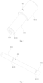
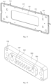
- An electrical connector in another example of the embodiment can be a floating electrical connector, and include a baseplate 10 to provide a mounting base, a floating plate 20 floatingly connected to the baseplate 10 by means of an elastic member 30, and a pole mounting seat 50 fixed to the floating plate 20 by means of screws 15.
- the pole mounting seat 50 defines a mounting groove for mounting the elastic pole 40.
- the elastic pole 40 is mounted on the pole mounting seat 50 by means of the mounting groove.
- the baseplate 10 and the floating plate 20 define mounting openings through which the cable connecting terminal of the elastic pole 40 passes.
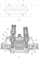
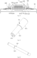
- an electrical connector of an embodiment according to the invention includes an electric-connector vehicle end 60 and an electrical connector battery end 70.
- the electric-connector vehicle end 60 includes a vehicle-end floating plate 61, a vehicle-end fixing plate 62, and a high-voltage assembly 63, the high-voltage assembly 63 has two ends connected to the vehicle-end floating plate 61 and the vehicle-end fixing plate 62 respectively.
- a floating electrical connection of the high-voltage assembly 63 is achieved by means of the vehicle-end floating plate 61 and the vehicle-end fixing plate 62, thereby ensuring stability of the electrical connector during connection and operation.
- the high-voltage assembly 63 includes a pole component 80 and a high-voltage pin 631, the high-voltage pin 631 is connected to the vehicle-end fixing plate 62, the pole component 80 is connected to the vehicle-end floating plate 61, and the high-voltage pin 631 is electrically connected to the pole component 80.
- At least one conductive elastic body is arranged between the high-voltage pin 631 and the pole component 80, the conductive elastic body is used to keep electrical connection all along when the high-voltage pin 631 is floating relative to the pole component 80.
- the floating connection between the high-voltage pin 631 and the pole component 80 by means of the conductive elastic body, which improves stability of the electrical connection between the high-voltage pin 631 and the pole component 80.
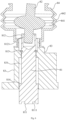
- the pole component 80 includes a pole 81, a conductive joint 82, at least one conductive elastic member (not shown in the drawings).
- the pole 81 has two ends provided with a first electrical connecting portion 811 and a second electrical connecting portion 812 respectively.
- the first electrical connecting portion 811 is electrically connected to the conductive elastic member, the conductive elastic member can be electrically connected to the first electrical connecting portion 811 by crimping.
- the first electrical connecting portion 811 is electrically connected to an electric-connector battery end 70.
- the conductive elastic member is arranged between the first electrical connecting portion 811 and electrical connector battery end 70, achieving the floating connection between the pole 81 and electrical connector battery end 70, such that the electrical connection is more stable, especially for the electrical connection in the case of dynamic load and vibration environment, abnormal situations, such as failure on the electrical connection, overburning, etc., due to loose connection can be effectively prevented, and the reliability of the electrical connection is greatly enhanced and the service life is prolonged.
- the conductive joint 82 includes a flexible member 821 and a first contact 822.
- the first contact 822 has a first end connected to the flexible member 821 and a second end electrically connected to the second electrical connecting portion 812.
- the flexible member 821 is electrically connected to the high-voltage pin 831, the flexible member 821 is arranged between the pole 81 and the high-voltage pin 831, achieving the floating connection between the pole 81 and the high-voltage pin 631, abnormal situations, such as failure on the electrical connection, overburning, etc., due to loose connection can be effectively prevented, and the stability of the electrical connection of the pole 81 in the electrical connector is improved.
- the pole component 80 can include a pole plate 83, the pole plate 83 has a receiving chamber 831.
- the receiving chamber 831 has two ends each provided with a guiding hole, the pole 81 runs through the receiving chamber 831 with two ends extending out of two guiding holes. With the two guiding holes, the pole 81 can only move back and forth in a direction defined by the two guiding holes, the pole 81 is effectively limited, offset and malposition of the pole 81 can be prevented, and the electrical connection of the pole 81 is improved.
- the pole 81 has an end adjacent to the conductive joint 82, and the end has an outer wall provided with a limiting portion, the limiting portion has a first end connected to an outer surface of the pole 81 and a second end extending and protruding in a radial direction of the pole 81. That is, the limiting portion is protruding.
- the limiting portion can be a snap ring 813, the pole 81 defines an annular groove (not shown in the drawings) in an outer wall, and the snap ring 813 is snapped into the annular groove, such that the pole 81 can be mounted to and dismounted from the pole plate 83 with a simple structure.
- the pole 81 has another end way from the conductive joint 82, and the another end has an outer wall provided with a protrusion 814, the protrusion 814 extends out in the radial direction of the pole 81, and the protrusion 814 runs through the guiding hole, that is the protrusion 814 is protruding.
- the pole component 80 can include an elastic body (not shown in the drawings), the elastic body is located in the receiving chamber 831 and between the snap ring 813 and the protrusion 814, and the elastic body has two ends abutting an inner wall of the receiving chamber 831 and the protrusion 814 respectively.
- the elastic body With the elastic body, a force is exerted on the pole 81 in the direction along the first electrical connecting portion 811, and the first electrical connecting portion 811 can retract under stress upon contact with the electric-connector battery end 70, thereby reducing rigid impact on the first electrical connecting portion 811.
- the floating connection can be achieved during the electrical connection, desired contact between the first electrical connecting portion 811 and electrical connector battery end 70 is ensured, and the stability of the electrical connection between the first electrical connecting portion 811 and electrical connector battery end 70 is greatly improved.
- the elastic body can be a reset spring, the pole 81 runs through the reset spring.
- the reset spring has high elasticity and good property, and is easy to restore after removing an external force. Meanwhile, the reset spring exerts a force on the pole 81, such that the pole 81 is under uniform force, and offset and malposition of the pole 81 can be effectively prevented.
- the insulating bush 84 can be provided with a wavy portion 842. With the wavy portion 842 on an outer surface of the insulating bush 84, the insulating bush 84 has good flexibility, deformability of the insulating bush 84 can be improved, and the insulating bush 84 can insulate and seal the conductive joint 82 in a better way.
- At least one second conductive spring 8221 can be pressed between the pole 81 and the first contact 822. With the second conductive spring 8221, floating connection between the pole 81 and the first contact 822 is achieved, and stability of the electrical connection between the pole 81 and the conductive joint 82 is improved.
- the high-voltage pin 631 can be connected to the conductive joint 82 by means of a socket, the socket has a second cavity portion at each of two ends thereof, and the high-voltage pin 631 and the second contact 823 are inserted in second cavity portions at the two ends of the socket respectively.
- the high-voltage pin 631 and the second contact 823 each define at least one second annular spring groove in outer walls thereof, the third conductive spring 8231 is pressed in the second annular spring groove, and the third conductive spring 8231 is pressed between the second cavity portion and the second annular spring groove. Intensity of connection and arrangement of the third conductive spring 8231 is effectively enhanced, and the electrical connection is more stable.
- the flexible member 821 includes a cavity body 8211, the cavity body 8211 has two ends connected to the first contact 822 and the second contact 823 respectively.
- the cavity body 8211 is made of flexible material.
- the cavity body 8211 can be stretch and compressed, or twisted in the radial direction, to adapt relative displacement of connection between the conductive joint 82 and the pole 81, and relative displacement of connection between the conductive joint 82 and the high-voltage pin 631 in the axial direction and radial direction, performance of the electrical connection of the conductive joint 82 can be prevented from getting worse due to changes of relative displacement, stability of electrical connection of the high-voltage assembly 63 is greatly improved.
- the cavity body 8211 is crimped or welded to the first contact 822 and the second contact 823, thereby enhancing intensity of structural connection of the conductive joint 82, and ensuring stability of the electrical connection of the conductive joint 82.
- the cavity body 8211 can be a spherical-like elastic cavity body enclosed by a plurality of flexible conductive bars, the cavity body 8211 also can be a spherical-like elastic cavity body enclosed by a grid flexible conductive member.
- the cavity body 8211 also can be a spherical-like elastic cavity body woven from metal wires or formed by stretching a metal conductive tape.
- the flexible member 821 further includes a spring 8212, the spring 8212 is located in the cavity body 8211 and is located between the first contact 822 and the second contact 823.
- the spring 8212 has two ends connected to the first contact 822 and the second contact 823 respectively by welding and crimping. With the spring 8212, structural strength of the conductive joint 82 is effectively enhanced, such that electrical connection of the conductive joint 82 can be ensured even relative displacement of two ends the flexible member 821 changes. Meanwhile, the spring 8212 is conductive, which further improves stability of the electrical connection between the first contact 822 and the second contact 823.
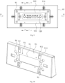
- An electrical connector in the embodiment generally includes a baseplate 90 and a floating plate 100.
- the baseplate 90 includes a hollow baseplate mounting opening 91.
- the floating plate 100 is movably mounted on a surface of the baseplate 90 by means of an elastic member 110.
- the floating plate 100 is provided with an elastic pole 120 for electrical connection.
- the elastic pole 120 When the electrical connector is used to charge a battery to be charged, the elastic pole 120 is inserted into a charging interface of the battery to be charged, the elastic pole 120 can have certain elasticity for stretching out and drawing back after being in contact with the battery to be charged, which enhances a contact effect at a contact point.
- the floating plate 100 translates relative to the baseplate 90 to some extent under the control of the elastic member 110 when the floating plate 100 is affected by an external force, thereby improving connection of the elastic pole and preventing rigid damage.
- the first fixing block 921 and the second fixing block 922 can be formed by portions of the baseplate 90 and the floating plate 100, and the first fixing block 921 is spaced apart from the second fixing block 922 at a certain distance to receive the elastic member 110.
- the elastic member 110 in the embodiment can be a spring or an elastic steel roll.
- the spring can have two ends connected to the first fixing block 921 and the second fixing block 922.
- the first fixing block 921 and the second fixing block 922 have dimensions smaller than an inner diameter of the spring, such that the spring is fitted over the first and second fixing block.
- the floating plate 100 and the baseplate 90 can define first fixing holes 94, 102 respectively, a guiding member 95 is mounted in the first fixing holes 94, 102 to limit them together, the guiding member 95 includes a guiding sleeve and a guiding screw, the guiding sleeve 95 is mounted on the baseplate 90, the guiding screw runs through the floating plate 100 to be threadedly connected to the guiding sleeve 95, the guiding sleeve 95 located at the baseplate 90 has a portion in the first fixing hole 102, and the portion has a diameter less than that of the first fixing hole 102.
- the floating plate 100 can define a hollow floating-plate mounting opening 103 in a middle portion, a pole mounting plate 130 specially for mounting the elastic pole 120 is fixed to the mounting opening 103.
- the elastic pole 120 can be easily mounted, and the whole electrical connector can be easily dismounted and maintained.
- a fixed connection can be provided between the pole mounting plate 130 and the floating plate 100.
- the floating plate 100 and the pole mounting plate 130 define second fixing holes 104, 131 respectively through which a fixing member runs, the baseplate 90 defines a receiving hole 95 at a position corresponding to the second fixing holes 104, 131 for receiving the fixing member.
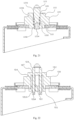
- the pole body 121 has a first end, an electrical contact terminal 1211, in contact with the battery, and a second end, a cable connecting terminal 1212, for connection with a supply line.
- the pole body 121 defines an annular groove 1213 in an outer surface.
- the electrical contact terminal 1211 can be flat for increasing a contact area.
- the annular groove 1213 can be used to mount a limiting member, such that the elastic pole 120 is mounted on the pole mounting plate in limiting manner.
- the limiting member is a snap ring, the snap ring has an outer diameter larger than that of the pole body at a portion inserted into the annular grooves1213, such that the spring is limited on the pole body, and the spring cooperates with the snap ring to floatingly mount the pole body on the pole mounting seat.
- the boss 132 can define a high-voltage mounting hole 56 with a step
- the high-voltage pole 123 is of a shape corresponding to that of the high-voltage mounting hole 56 and the high-voltage pole 123 can be inserted into the high-voltage mounting hole 56, the inserted high-voltage pole 123 is limited in the high-voltage mounting hole 56 by the spring 122 and the snap ring 1215 locked in the annular grooves 1213.
- a specific mounting structure can be as follows, the high-voltage mounting hole 136 includes a first mounting segment 1361 and a second mounting segment 1362, and the second mounting segment 1362 has a diameter smaller than that of the first mounting segment 1361, a diameter of the pole body with the electrical contact terminal of the high-voltage pole 123 is larger than that of the pole body with the cable connecting terminal.
- the pole body at the cable connecting terminal is a diameter-reducing segment 1232, and the pole body at the electrical contact terminal is a diameter-constant segment 1231.
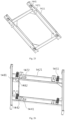
- a battery charging board 140 for an electric vehicle provided by an embodiment which does not fall within the subject-matter of the claimed invention and generally includes an upper frame assembly 141, a lower frame assembly 142 and a floating charging plate 143.
- the upper frame assembly 141 is used to place a battery to be charged and includes an upper frame 1411 supporting the battery.
- the lower frame assembly 142 is used to elastically support the upper frame 1411, the lower frame assembly 142 includes a lower frame 1421 and an elastic device 145 arranged on an upper surface of the lower frame 1421. With the elastic device 145, the upper frame 141 can move downwards at a specified distance under the action of a gravity of the battery after the battery is in position.
- the snapping plate 1412 has a stage of a height equal to that of the right-angle mounting bars 1491.
- the supporting plate 149 is locked on the snapping plate 1412 by means of the right-angle mounting bars 1491, each of the two right-angle mounting bars 1491 is put on the corresponding stage of the snapping plate 1412 by means of one right-angle side, the supporting plate 149 can be prevented from lateral movement, a direction of the limited movement corresponds to that of movement of the floating charging plate 143, a fault of connection between the battery and the floating electrical connector 1431 can be prevented during downwards movement of the battery.
- a limiting device 147 can be provided between the upper frame 1411 and the lower frame 1421 for limiting movement of the upper frame 1411 relative to the lower frame after placement of the battery.
- the limiting device 147 can include a taper positioning rod 1471 arranged on a lower surface of the upper frame 1411 and a taper positioning base 1472 arranged on an upper surface of the lower frame 1421 and corresponding to the taper positioning rod 1471 in position.
- the taper positioning rod 1471 at a bottom of the upper frame 1411 can be inserted into the taper positioning base 1472 at a top of the lower frame 1421, thereby preventing the upper frame 1411 from moving during charging.
- a plurality of taper positioning rods 1471 can be arranged on the lower surface of the upper frame, and a plurality of taper positioning bases 1472 can be arranged on the upper surface of the lower frame.
- the lower frame assembly 142 in order to prevent the upper frame 1411 from getting out of control under the elastic device 145 and to limit a moving direction of the upper frame 1411, the lower frame assembly 142 can be provided with a limiting device 144 for limiting a downward moving track of the upper frame assembly 141, and the limiting device 144 can also limit a range of up-down movement of the upper frame 1411.
- the limiting device 144 includes a limiting plate 1441 mounted on the lower frame 1421 and having a longitudinal sliding groove 1442, and a limiting rod 1443 arranged on the upper frame 1411 and inserted in the longitudinal sliding groove 1442.
- the limiting plate 1441 surrounds the lower frame 1421, the longitudinal sliding groove 1442 in the limiting plate is perpendicular to the lower frame 1421, the limiting rod 1443 of the upper frame 1411 is arranged at a position corresponding to the limiting plate 1441 and inserted into the longitudinal sliding groove 1442.
- the upper frame 1411 is jacked up by the elastic device 145, the limiting rod 1443 is located at a top end of the longitudinal sliding groove 1442.
- the upper frame 1411 can only move along the longitudinal sliding groove 1442 because the longitudinal sliding groove 1442 limits the limiting rod 1443, such that the moving direction of the upper frame 1411 is limited, a plurality of limiting plates can be arranged at an edge of the upper frame to improve a limiting effect.
- the limiting effect of the limiting device 147 and the connection effect of the floating charging plate 143 can be improved by means of the embodiment.
- the mounting seat 1432 in order to enable the mounting seat 1432 to act synchronously with the upper frame 1411 and reach a designated position, the mounting seat 1432 can be connected to the upper frame 1411 by means of a slide rail device 146 and connected to the lower frame 1421 by means of an orienting device 148.
- the slide rail device 146 is used to limit movement, towards the battery along the upper frame, of the mounting seat 1432 when the mounting seat 1432 is pressed down by the upper frame 1411, the movement can allow the floating electrical connector 1431 on the mounting seat 1432 to automatically make electrical contact with the lowered battery.
- a positioning device 148 is used to guide the floating charging plate to move along with the battery and corresponding to an electrical connection mechanism on a surface of the battery.
- a specific slide rail device 146 is provided.
- the slide rail device 146 can include a sliding block 1462 mounted on a lower surface of the mounting seat 1432 and having a snapping groove and a slide rail 1461 mounted on an end of the upper frame 1411.
- the snapping groove of sliding block 1462 is snapped into the slide rail 1461, such that the mounting seat 1432 is slidingly connected to the upper frame 1411, when the upper frame 1411 is lowered, the slide rail 1461 exerts a force pulling the sliding block 1462 downwards, such that the mounting seat 1432 moves along the slide rail 1461 under limit of the orienting device 148.
- the floating electrical connector 1431 is connected to the battery on the upper frame 1411 via insertion.
- an orienting device 148 includes a pulley base 1483 arranged on a lower surface of the mounting seat 1432 and having a pulley 1484, and an orientation limiting base 1481 mounted on an upper surface of the lower frame 1421 and having an oblique groove 1482, the oblique groove 1482 inclines in a direction the same as that of the slide rail 1461.
- the pulley base 1483 can be two parallel plates, while the pulley 1484 is perpendicularly connected between the two plates.
- an angle of inclination of the oblique groove 1482 is the same as a sliding and downwards movement track of the mounting seat 1432, and the movement of the mounting seat 1432 can be made not to diverge an insertion track with the battery.
Landscapes
- Chemical & Material Sciences (AREA)
- Chemical Kinetics & Catalysis (AREA)
- Electrochemistry (AREA)
- General Chemical & Material Sciences (AREA)
- Engineering & Computer Science (AREA)
- Power Engineering (AREA)
- Transportation (AREA)
- Mechanical Engineering (AREA)
- Details Of Connecting Devices For Male And Female Coupling (AREA)
- Connection Of Batteries Or Terminals (AREA)
Claims (12)
- Eine Polkomponente (80) für eine Hochspannungsanordnung zum Laden von Elektrofahrzeugen, umfassend:einen Pol (81), eine leitende Verbindung (82) und mindestens ein leitendes elastisches Element zur Herstellung einer schwimmenden Verbindung zwischen dem Pol (81) und einem elektrischen Verbinderbatterieende (70),wobei der Pol (81) zwei Enden hat, die mit einem ersten elektrischen Verbindungsabschnitt (811) bzw. einem zweiten elektrischen Verbindungsabschnitt (812) versehen sind, wobei der erste elektrische Verbindungsabschnitt (811) elektrisch mit dem leitenden elastischen Element verbunden ist,die leitende Verbindung (82) ein flexibles Element (821) und einen ersten Kontakt (822) umfasst, und der erste Kontakt (822) ein erstes Ende hat, das mit dem flexiblen Element (821) verbunden ist, und ein zweites Ende, das elektrisch mit dem zweiten elektrischen Verbindungsabschnitt (812) verbunden ist;die leitende Verbindung (82) ferner einen zweiten Kontakt (823) zum Anschließen eines Hochspannungsstifts (631) umfasst und das flexible Element (821) zwei Enden aufweist, die mit dem ersten Kontakt (822) bzw. dem zweiten Kontakt (823) verbunden sind;dadurch gekennzeichnet, dass das biegsame Element (821) einen Hohlkörper (8211) umfasst, der aus einem biegsamen leitenden Material besteht und zwei Enden aufweist, die mit dem ersten Kontakt (822) bzw. dem zweiten Kontakt (823) verbunden sind,das biegsame Element (821) ferner eine leitende Feder (8212) umfasst, die sich in dem Hohlraumkörper (8211) befindet und mit dem ersten Kontakt (822) und dem zweiten Kontakt (823) verbunden ist.
- Polkomponente (80) nach Anspruch 1, dadurch gekennzeichnet, dass das Polkomponente (80) eine Polplatte (83) mit einer Aufnahmekammer (831) umfasst, wobei zwei Enden der Aufnahmekammer (831) jeweils ein Führungsloch definieren, der Pol (81) durch die Aufnahmekammer (831) verläuft und zwei Enden des Pols (81) aus zwei Führungslöchern herausgeführt sind.
- Polkomponente (80) nach Anspruch 2, dadurch gekennzeichnet, dass die Polkomponente eine Isolierbuchse (84) umfasst, wobei die Isolierbuchse (84) mit der Polplatte (83) verbunden ist und darin einen Hohlraum (841) definiert, und die leitende Verbindung (82) in dem Hohlraum (841) angeordnet ist.
- Polkomponente (80) nach Anspruch 3, dadurch gekennzeichnet, dass die Isolierbuchse (84) mit einem wellenförmigen Abschnitt (842) versehen ist und/oder die Isolierbuchse (84) durch Einschnappen mit der Polplatte (83) verbunden ist.
- Polkomponente (80) nach Anspruch 1, dadurch gekennzeichnet, dass der Hohlraumkörper (8211) mit dem ersten Kontakt (822) und dem zweiten Kontakt (823) verpresst oder verschweißt ist.
- Polkomponente (80) nach Anspruch 1, dadurch gekennzeichnet, dass der Pol (81) ein an die leitende Verbindung (82) angrenzendes Ende aufweist und das Ende eine Außenwand hat, die mit einem Begrenzungsabschnitt versehen ist, wobei der Begrenzungsabschnitt ein erstes Ende hat, das mit einer Außenfläche des Pols (81) verbunden ist, und ein zweites Ende, das sich in einer radialen Richtung des Pols (81) erstreckt und vorsteht, und wobei der Begrenzungsabschnitt außerhalb der Aufnahmekammer (831) angeordnet ist und an einer Außenfläche der Aufnahmekammer (831) anliegt.
- Polkomponente (80) nach Anspruch 6, dadurch gekennzeichnet, dass der Mast (81) eine mit einer Ringnut versehene Außenwand aufweist und der Begrenzungsabschnitt ein in die Ringnut eingebetteter Sprengring (813) ist.
- Polbauteil (80) nach Anspruch 7, dadurch gekennzeichnet, dass der Pol (81) an der Außenwand mit einem Vorsprung (814) versehen ist, der Vorsprung (814) sich in radialer Richtung des Pols (81) nach außen erstreckt und vorsteht, der Vorsprung (814) durch das Führungsloch verläuft, die Polkomponente (80) einen elastischen Körper umfasst, der elastische Körper in der Aufnahmekammer (831) und zwischen dem Begrenzungsabschnitt und dem Vorsprung (814) angeordnet ist, und der elastische Körper zwei Enden aufweist, die an einer Innenwand der Aufnahmekammer (831) bzw. dem Vorsprung (814) anliegen.
- Polkomponente (80) nach einem der Ansprüche 1 bis 8, dadurch gekennzeichnet, dass der erste elektrische Verbindungsabschnitt (811) mit mindestens einer Anbringungskammer (8111) versehen ist, das leitende elastische Element einen Kontaktabschnitt und einen Druckabschnitt aufweist, der Druckabschnitt in der Anbringungskammer (8111) angebracht ist und der Kontaktabschnitt aus einer Außenfläche des ersten elektrischen Verbindungsabschnitts (811) herausragt,vorzugsweise ist das leitende elastische Element eine erste leitende Feder;noch bevorzugter ist mindestens eine zweite leitende Feder (8221) zwischen dem Pol (81) und dem ersten Kontakt (822) vorgesehen und gepresst, der zweite elektrische Verbindungsabschnitt (812) ist mit einem ersten Hohlraumabschnitt versehen, der erste Kontakt (822) hat eine Außenwand, die mit mindestens einer ersten ringförmigen Federnut versehen ist, und die zweite leitende Feder (8221) ist zwischen dem ersten Hohlraumabschnitt und der ersten ringförmigen Federnut vorgesehen und gepresst.
- Hochspannungsanordnung (63), dadurch gekennzeichnet, dass die Hochspannungsanordnung (63) die Polkomponente (80) nach einem der Ansprüche 1 bis 9 umfasst, wobei ein Hochspannungsstift (631) mit der leitenden Verbindung (82) elektrisch verbunden ist, mindestens ein leitfähiger elastischer Körper vorgesehen ist und zwischen den Hochspannungsstift (631) und die leitfähige Verbindung (82) gepresst wird, und der leitfähige elastische Körper dazu dient, die elektrische Verbindung zwischen dem Hochspannungsstift (631) und der leitfähigen Verbindung (82) im Falle eines Schwebens zwischen dem Hochspannungsstift (631) und der leitfähigen Verbindung (82) aufrecht zu erhalten.
- Hochspannungsanordnung (63) nach Anspruch 10, dadurch gekennzeichnet, dass der Hochspannungsstift (631) mit der leitenden Verbindung (82) mittels einer Buchse verbunden ist, zwei Enden der Buchse jeweils mit einem zweiten Hohlraumabschnitt versehen sind, eine Außenwand des Hochspannungsstifts (631) und eine Außenwand der leitenden Verbindung (82) jeweils mindestens eine zweite ringförmige Federnut definieren und der leitende elastische Körper zwischen dem zweiten Hohlraumabschnitt und der zweiten ringförmigen Federnut gepresst ist;
und/oder der leitfähige elastische Körper eine dritte leitfähige Feder (8231) ist. - Elektrischer Verbinder, dadurch gekennzeichnet, dass der elektrische Verbinder die Hochspannungsanordnung (63) nach einem der Ansprüche 10 bis 11 umfasst.
Applications Claiming Priority (5)
| Application Number | Priority Date | Filing Date | Title |
|---|---|---|---|
| CN201720091235.5U CN206558797U (zh) | 2017-01-23 | 2017-01-23 | 弹性极柱和浮动电连接器 |
| CN201710050225.1A CN108063345A (zh) | 2017-01-23 | 2017-01-23 | 电连接器 |
| CN201710050417.2A CN108063194A (zh) | 2017-01-23 | 2017-01-23 | 一种电动汽车的电池充电盘 |
| CN201710487668.7A CN108155496B (zh) | 2017-06-23 | 2017-06-23 | 极柱组合件、高压组件和电连接器 |
| PCT/CN2018/073747 WO2018133871A1 (zh) | 2017-01-23 | 2018-01-23 | 弹性极柱、组合件、高压组件、电连接器和电池充电盘 |
Publications (4)
| Publication Number | Publication Date |
|---|---|
| EP3573194A1 EP3573194A1 (de) | 2019-11-27 |
| EP3573194A4 EP3573194A4 (de) | 2020-12-23 |
| EP3573194B1 true EP3573194B1 (de) | 2025-04-02 |
| EP3573194C0 EP3573194C0 (de) | 2025-04-02 |
Family
ID=62908429
Family Applications (1)
| Application Number | Title | Priority Date | Filing Date |
|---|---|---|---|
| EP18741039.4A Active EP3573194B1 (de) | 2017-01-23 | 2018-01-23 | Elastischer pol, kombiniertes element, hochspannungsanordnung, elektrischer verbinder und batterieladeplatte |
Country Status (3)
| Country | Link |
|---|---|
| EP (1) | EP3573194B1 (de) |
| JP (2) | JP6992074B2 (de) |
| WO (1) | WO2018133871A1 (de) |
Families Citing this family (30)
| Publication number | Priority date | Publication date | Assignee | Title |
|---|---|---|---|---|
| CN109119792B (zh) * | 2017-06-23 | 2020-07-17 | 上海电巴新能源科技有限公司 | 电连接装置 |
| CN110931910B (zh) * | 2018-08-29 | 2025-02-21 | 奥动新能源汽车科技有限公司 | 电池包支架总成、电池包组件和电动汽车 |
| CN109546732A (zh) * | 2018-12-28 | 2019-03-29 | 北京汉能光伏投资有限公司 | 太阳能储能装置 |
| CN111721465A (zh) * | 2019-03-21 | 2020-09-29 | 上海时滨电子科技有限公司 | 一种方便连接接头的压力仪表 |
| CN110048480B (zh) * | 2019-04-22 | 2025-01-14 | 无锡快仓智能科技有限公司 | 充电头浮动机构及具有该机构的充电桩 |
| CN110967531B (zh) * | 2019-11-25 | 2022-09-20 | 国网山东省电力公司滨州市沾化区供电公司 | 一种电力运维检修工具检测架 |
| CN111251918A (zh) * | 2020-02-14 | 2020-06-09 | 奥动新能源汽车科技有限公司 | 充电仓、含其的充电架、换电站和储能站 |
| CN119261610A (zh) * | 2020-04-03 | 2025-01-07 | 奥动新能源汽车科技有限公司 | 充电装置、充电总成以及换电站 |
| CN111610443B (zh) * | 2020-05-08 | 2024-10-11 | 珠海市运泰利自动化设备有限公司 | 一种自动定位保持装置 |
| CN111762344B (zh) * | 2020-07-01 | 2023-12-22 | 中国人民解放军63921部队 | 一种连接装置和可更换太阳翼结构 |
| EP4009423B1 (de) * | 2020-09-30 | 2025-07-09 | Contemporary Amperex Technology (Hong Kong) Limited | Batterie, batterieanordnung, elektrische vorrichtung sowie herstellungsverfahren und vorrichtung für eine batterie |
| CN112682602B (zh) * | 2021-01-12 | 2025-06-13 | 上海亚大汽车塑料制品有限公司 | 一种对接位置可调的管路组件 |
| DE102021105606A1 (de) | 2021-03-09 | 2022-09-15 | Lisa Dräxlmaier GmbH | Vorrichtung zum elektrischen kontaktieren von einem ladestecker und einer ladedose |
| CN113067066B (zh) * | 2021-04-01 | 2022-11-25 | 深圳市嘀嗒来电科技有限公司 | 一种可单独更换电池的锂电池组及其使用方法 |
| CN113291243A (zh) * | 2021-04-02 | 2021-08-24 | 深圳市鑫煜控股有限公司 | 一种电动汽车换电用浮动式连接器 |
| CN114069302B (zh) * | 2021-10-18 | 2023-08-15 | 武汉市格力浦电子有限公司 | 一种高可靠性的高速连接器 |
| CN114030380B (zh) * | 2021-11-03 | 2023-06-27 | 大连海事大学 | 一种用于无线充电的随动装置 |
| CN114148200B (zh) * | 2021-11-30 | 2023-12-26 | 国网重庆市电力公司营销服务中心 | 一种电动汽车充电桩异常数据处理装置 |
| CN114725601B (zh) * | 2022-03-24 | 2023-09-01 | 福州福享汽车工业有限公司 | 一种具有防坠功能的倾斜式储能电池柜 |
| CN115458980A (zh) * | 2022-04-29 | 2022-12-09 | 奥动新能源汽车科技有限公司 | 电连接装置及电动汽车 |
| CN114940083A (zh) * | 2022-05-05 | 2022-08-26 | 许继电源有限公司 | 一种自动充电连接装置 |
| CN114843834B (zh) * | 2022-05-13 | 2024-10-01 | 乐清市金龙电子实业有限公司 | 一种充电枪 |
| CN114976775B (zh) * | 2022-06-14 | 2023-10-20 | 南通诚弘精密机械有限公司 | 一种防震动脱落的电连接器 |
| CN115308444B (zh) * | 2022-07-15 | 2025-05-02 | 华能聊城热电有限公司 | 一种测量高压设备绝缘电阻的专用辅助工具 |
| CN115431801B (zh) * | 2022-08-30 | 2023-03-03 | 解本艳 | 一种用于新能源汽车的磁吸式充电口盖组件 |
| CN115782554B (zh) * | 2022-10-11 | 2023-08-29 | 上汽通用五菱汽车股份有限公司 | 一种混合动力装置及混合动力系统 |
| CN115986495A (zh) * | 2023-02-23 | 2023-04-18 | 国创移动能源创新中心(江苏)有限公司 | 一种电连接系统 |
| CN116298425B (zh) * | 2023-03-21 | 2026-03-31 | 速博达(深圳)自动化有限公司 | 一种双端子电池扣板系统及扣板方法 |
| CN118040206A (zh) * | 2024-02-01 | 2024-05-14 | 广州市均能科技有限公司 | 一种电池包定位结构和储能系统 |
| CN119087005B (zh) * | 2024-09-10 | 2025-07-18 | 国网江苏省电力有限公司泰州供电分公司 | 一种便于携带的不停电换表装置 |
Citations (1)
| Publication number | Priority date | Publication date | Assignee | Title |
|---|---|---|---|---|
| EP3553893B1 (de) * | 2016-12-12 | 2022-11-16 | Shanghai Dianba New Energy Technology Co., Ltd. | Elektrische verbindungsvorrichtung |
Family Cites Families (19)
| Publication number | Priority date | Publication date | Assignee | Title |
|---|---|---|---|---|
| JPS5810383U (ja) * | 1981-07-14 | 1983-01-22 | 三菱電機株式会社 | 接続装置 |
| JPH10294157A (ja) * | 1997-04-21 | 1998-11-04 | Harness Sogo Gijutsu Kenkyusho:Kk | 携帯電話の中継コネクタ構造 |
| JPH1126056A (ja) * | 1997-06-27 | 1999-01-29 | Tokai Rika Co Ltd | 給電装置 |
| JP2000045656A (ja) | 1998-07-28 | 2000-02-15 | Best Oume:Kk | 移動扉への通電装置及びこれを備えた防災用扉 |
| EP2015403B1 (de) * | 2007-07-12 | 2017-05-10 | ODU GmbH & Co KG. | Elektrischer Steckverbinder sowie Verbindungseinrichtung für einen solchen Steckverbinder |
| US8052427B2 (en) * | 2009-04-01 | 2011-11-08 | GM Global Technology Operations LLC | Connector assembly for coupling an electric motor to a power source |
| JP5294038B2 (ja) * | 2010-03-08 | 2013-09-18 | 住友電装株式会社 | 雌端子金具 |
| CN102683936A (zh) * | 2011-03-16 | 2012-09-19 | 贵阳普天物流技术股份有限公司 | 电动车换电充电系统平面连接器结构及其连接方法 |
| CN202534729U (zh) * | 2012-04-18 | 2012-11-14 | 迪吉亚节能科技股份有限公司 | 碰触式导电极柱 |
| CN202772633U (zh) | 2012-09-13 | 2013-03-06 | 上海电巴新能源科技有限公司 | 电动车车载动力电池充电平台 |
| CN203013995U (zh) * | 2012-11-16 | 2013-06-19 | 罗向平 | 连接器 |
| CN203466364U (zh) * | 2013-09-17 | 2014-03-05 | 四川永贵科技有限公司 | 一种带有浮动装置的电连接器插座 |
| CN105185943A (zh) * | 2015-10-16 | 2015-12-23 | 力帆实业(集团)股份有限公司 | 一种电动车用动力电池快速连接装置 |
| CN106207542B (zh) * | 2016-08-30 | 2018-11-27 | 四川永贵科技有限公司 | 浮动式端面接触连接器 |
| CN205985557U (zh) * | 2016-09-09 | 2017-02-22 | 上海电巴新能源科技有限公司 | 电连接器的电连接结构及电连接器 |
| CN106299782B (zh) * | 2016-09-09 | 2018-08-10 | 上海电巴新能源科技有限公司 | 电连接器 |
| CN106328878B (zh) * | 2016-11-16 | 2023-04-07 | 奥动新能源汽车科技有限公司 | 用于电动汽车电池模组的双头连接装置 |
| CN207165831U (zh) * | 2017-01-23 | 2018-03-30 | 上海电巴新能源科技有限公司 | 电连接器 |
| CN206558797U (zh) * | 2017-01-23 | 2017-10-13 | 上海电巴新能源科技有限公司 | 弹性极柱和浮动电连接器 |
-
2018
- 2018-01-23 EP EP18741039.4A patent/EP3573194B1/de active Active
- 2018-01-23 WO PCT/CN2018/073747 patent/WO2018133871A1/zh not_active Ceased
- 2018-01-23 JP JP2019539919A patent/JP6992074B2/ja active Active
-
2021
- 2021-12-08 JP JP2021199406A patent/JP7309831B2/ja active Active
Patent Citations (1)
| Publication number | Priority date | Publication date | Assignee | Title |
|---|---|---|---|---|
| EP3553893B1 (de) * | 2016-12-12 | 2022-11-16 | Shanghai Dianba New Energy Technology Co., Ltd. | Elektrische verbindungsvorrichtung |
Also Published As
| Publication number | Publication date |
|---|---|
| EP3573194A1 (de) | 2019-11-27 |
| JP2022033936A (ja) | 2022-03-02 |
| WO2018133871A1 (zh) | 2018-07-26 |
| JP2020505735A (ja) | 2020-02-20 |
| EP3573194C0 (de) | 2025-04-02 |
| JP7309831B2 (ja) | 2023-07-18 |
| JP6992074B2 (ja) | 2022-02-03 |
| EP3573194A4 (de) | 2020-12-23 |
Similar Documents
| Publication | Publication Date | Title |
|---|---|---|
| EP3573194A1 (de) | Elastischer pol, kombiniertes element, hochspannungsanordnung, elektrischer verbinder und batterieladeplatte | |
| US12119692B2 (en) | Battery holder, power transfer device, electric vehicle and installation method for power transfer device | |
| KR102648070B1 (ko) | 전지측 전기 커넥터 및 전기적 연결 장치 | |
| CN108063345A (zh) | 电连接器 | |
| US20120071040A1 (en) | Terminal contacting part included in a jig for charging and discharging a secondary battery and the jig including the same | |
| CN207165831U (zh) | 电连接器 | |
| CN206558797U (zh) | 弹性极柱和浮动电连接器 | |
| CN205039365U (zh) | 用于电动车的连接器和电动车 | |
| KR101545202B1 (ko) | 154kV 초고압변전소 가스절연개폐장치의 케이블헤드챔버용 수직 승하강식 도체분리장치 | |
| CN216310054U (zh) | 一种超级电容器老化夹具 | |
| CN108169609B (zh) | 超级电容器并联充放电工装 | |
| CN216872271U (zh) | 带电作业并沟线夹 | |
| CN117638584B (zh) | 板对板连接器组件 | |
| CN209544677U (zh) | 1转3高压大电流连接器 | |
| CN219201721U (zh) | 一种避雷器接线装置 | |
| CN220474553U (zh) | 一种断路器接线端子 | |
| CN221281172U (zh) | 电芯测试装置 | |
| CN223872484U (zh) | 变压模块和电池充放电设备 | |
| CN217589501U (zh) | 下电极接地结构及真空镀膜设备 | |
| CN205207104U (zh) | 压缩机上盖卡片、压缩机上盖组件及压缩机 | |
| CN109449618B (zh) | 接地线组件 | |
| CN222825582U (zh) | 一种锂电池测试夹具 | |
| CN218182512U (zh) | 一种新型导电接触装置 | |
| CN223912081U (zh) | 一种集成型高压控制单元 | |
| CN115313099B (zh) | 一种新能源电池连接器 |
Legal Events
| Date | Code | Title | Description |
|---|---|---|---|
| STAA | Information on the status of an ep patent application or granted ep patent |
Free format text: STATUS: THE INTERNATIONAL PUBLICATION HAS BEEN MADE |
|
| PUAI | Public reference made under article 153(3) epc to a published international application that has entered the european phase |
Free format text: ORIGINAL CODE: 0009012 |
|
| STAA | Information on the status of an ep patent application or granted ep patent |
Free format text: STATUS: REQUEST FOR EXAMINATION WAS MADE |
|
| 17P | Request for examination filed |
Effective date: 20190823 |
|
| AK | Designated contracting states |
Kind code of ref document: A1 Designated state(s): AL AT BE BG CH CY CZ DE DK EE ES FI FR GB GR HR HU IE IS IT LI LT LU LV MC MK MT NL NO PL PT RO RS SE SI SK SM TR |
|
| AX | Request for extension of the european patent |
Extension state: BA ME |
|
| DAV | Request for validation of the european patent (deleted) | ||
| DAX | Request for extension of the european patent (deleted) | ||
| RIC1 | Information provided on ipc code assigned before grant |
Ipc: H01M 2/10 20060101ALI20200706BHEP Ipc: H01R 13/434 20060101AFI20200706BHEP Ipc: H01R 13/08 20060101ALN20200706BHEP Ipc: H01R 13/24 20060101ALI20200706BHEP Ipc: H01R 13/631 20060101ALI20200706BHEP Ipc: B60L 53/80 20190101ALI20200706BHEP Ipc: H01R 13/17 20060101ALI20200706BHEP |
|
| A4 | Supplementary search report drawn up and despatched |
Effective date: 20201123 |
|
| RIC1 | Information provided on ipc code assigned before grant |
Ipc: H01R 13/631 20060101ALI20201117BHEP Ipc: B60L 53/16 20190101ALI20201117BHEP Ipc: B60L 53/80 20190101ALI20201117BHEP Ipc: H01R 13/24 20060101ALI20201117BHEP Ipc: H01R 13/08 20060101ALN20201117BHEP Ipc: H01R 13/17 20060101ALI20201117BHEP Ipc: H01M 2/10 20060101ALI20201117BHEP Ipc: H01R 13/434 20060101AFI20201117BHEP |
|
| STAA | Information on the status of an ep patent application or granted ep patent |
Free format text: STATUS: EXAMINATION IS IN PROGRESS |
|
| 17Q | First examination report despatched |
Effective date: 20230104 |
|
| REG | Reference to a national code |
Ref country code: DE Ref legal event code: R079 Free format text: PREVIOUS MAIN CLASS: H01R0013631000 Ipc: H01R0013434000 Ref country code: DE Ref legal event code: R079 Ref document number: 602018080704 Country of ref document: DE Free format text: PREVIOUS MAIN CLASS: H01R0013631000 Ipc: H01R0013434000 |
|
| GRAP | Despatch of communication of intention to grant a patent |
Free format text: ORIGINAL CODE: EPIDOSNIGR1 |
|
| STAA | Information on the status of an ep patent application or granted ep patent |
Free format text: STATUS: GRANT OF PATENT IS INTENDED |
|
| RIC1 | Information provided on ipc code assigned before grant |
Ipc: H01R 13/08 20060101ALN20241106BHEP Ipc: B60L 53/16 20190101ALI20241106BHEP Ipc: B60L 53/80 20190101ALI20241106BHEP Ipc: H01R 13/24 20060101ALI20241106BHEP Ipc: H01R 13/17 20060101ALI20241106BHEP Ipc: H01R 13/631 20060101ALI20241106BHEP Ipc: H01R 13/434 20060101AFI20241106BHEP |
|
| INTG | Intention to grant announced |
Effective date: 20241115 |
|
| GRAS | Grant fee paid |
Free format text: ORIGINAL CODE: EPIDOSNIGR3 |
|
| GRAA | (expected) grant |
Free format text: ORIGINAL CODE: 0009210 |
|
| STAA | Information on the status of an ep patent application or granted ep patent |
Free format text: STATUS: THE PATENT HAS BEEN GRANTED |
|
| AK | Designated contracting states |
Kind code of ref document: B1 Designated state(s): AL AT BE BG CH CY CZ DE DK EE ES FI FR GB GR HR HU IE IS IT LI LT LU LV MC MK MT NL NO PL PT RO RS SE SI SK SM TR |
|
| REG | Reference to a national code |
Ref country code: GB Ref legal event code: FG4D |
|
| REG | Reference to a national code |
Ref country code: CH Ref legal event code: EP |
|
| REG | Reference to a national code |
Ref country code: IE Ref legal event code: FG4D |
|
| REG | Reference to a national code |
Ref country code: DE Ref legal event code: R096 Ref document number: 602018080704 Country of ref document: DE |
|
| U01 | Request for unitary effect filed |
Effective date: 20250428 |
|
| U07 | Unitary effect registered |
Designated state(s): AT BE BG DE DK EE FI FR IT LT LU LV MT NL PT RO SE SI Effective date: 20250506 |
|
| PG25 | Lapsed in a contracting state [announced via postgrant information from national office to epo] |
Ref country code: ES Free format text: LAPSE BECAUSE OF FAILURE TO SUBMIT A TRANSLATION OF THE DESCRIPTION OR TO PAY THE FEE WITHIN THE PRESCRIBED TIME-LIMIT Effective date: 20250402 |
|
| PG25 | Lapsed in a contracting state [announced via postgrant information from national office to epo] |
Ref country code: NO Free format text: LAPSE BECAUSE OF FAILURE TO SUBMIT A TRANSLATION OF THE DESCRIPTION OR TO PAY THE FEE WITHIN THE PRESCRIBED TIME-LIMIT Effective date: 20250702 Ref country code: GR Free format text: LAPSE BECAUSE OF FAILURE TO SUBMIT A TRANSLATION OF THE DESCRIPTION OR TO PAY THE FEE WITHIN THE PRESCRIBED TIME-LIMIT Effective date: 20250703 |
|
| PG25 | Lapsed in a contracting state [announced via postgrant information from national office to epo] |
Ref country code: PL Free format text: LAPSE BECAUSE OF FAILURE TO SUBMIT A TRANSLATION OF THE DESCRIPTION OR TO PAY THE FEE WITHIN THE PRESCRIBED TIME-LIMIT Effective date: 20250402 |
|
| PG25 | Lapsed in a contracting state [announced via postgrant information from national office to epo] |
Ref country code: HR Free format text: LAPSE BECAUSE OF FAILURE TO SUBMIT A TRANSLATION OF THE DESCRIPTION OR TO PAY THE FEE WITHIN THE PRESCRIBED TIME-LIMIT Effective date: 20250402 |
|
| PG25 | Lapsed in a contracting state [announced via postgrant information from national office to epo] |
Ref country code: RS Free format text: LAPSE BECAUSE OF FAILURE TO SUBMIT A TRANSLATION OF THE DESCRIPTION OR TO PAY THE FEE WITHIN THE PRESCRIBED TIME-LIMIT Effective date: 20250702 |
|
| PG25 | Lapsed in a contracting state [announced via postgrant information from national office to epo] |
Ref country code: IS Free format text: LAPSE BECAUSE OF FAILURE TO SUBMIT A TRANSLATION OF THE DESCRIPTION OR TO PAY THE FEE WITHIN THE PRESCRIBED TIME-LIMIT Effective date: 20250802 |
|
| PG25 | Lapsed in a contracting state [announced via postgrant information from national office to epo] |
Ref country code: SM Free format text: LAPSE BECAUSE OF FAILURE TO SUBMIT A TRANSLATION OF THE DESCRIPTION OR TO PAY THE FEE WITHIN THE PRESCRIBED TIME-LIMIT Effective date: 20250402 |
|
| PG25 | Lapsed in a contracting state [announced via postgrant information from national office to epo] |
Ref country code: CZ Free format text: LAPSE BECAUSE OF FAILURE TO SUBMIT A TRANSLATION OF THE DESCRIPTION OR TO PAY THE FEE WITHIN THE PRESCRIBED TIME-LIMIT Effective date: 20250402 |
|
| PG25 | Lapsed in a contracting state [announced via postgrant information from national office to epo] |
Ref country code: SK Free format text: LAPSE BECAUSE OF FAILURE TO SUBMIT A TRANSLATION OF THE DESCRIPTION OR TO PAY THE FEE WITHIN THE PRESCRIBED TIME-LIMIT Effective date: 20250402 |
|
| PLBE | No opposition filed within time limit |
Free format text: ORIGINAL CODE: 0009261 |
|
| STAA | Information on the status of an ep patent application or granted ep patent |
Free format text: STATUS: NO OPPOSITION FILED WITHIN TIME LIMIT |
|
| REG | Reference to a national code |
Ref country code: CH Ref legal event code: L10 Free format text: ST27 STATUS EVENT CODE: U-0-0-L10-L00 (AS PROVIDED BY THE NATIONAL OFFICE) Effective date: 20260211 |
|
| U20 | Renewal fee for the european patent with unitary effect paid |
Year of fee payment: 9 Effective date: 20260106 |
|
| 26N | No opposition filed |
Effective date: 20260105 |