EP3573394B1 - Procédé d'attribution de ressources, dispositif terminal, et dispositif de réseau - Google Patents
Procédé d'attribution de ressources, dispositif terminal, et dispositif de réseau Download PDFInfo
- Publication number
- EP3573394B1 EP3573394B1 EP17894439.3A EP17894439A EP3573394B1 EP 3573394 B1 EP3573394 B1 EP 3573394B1 EP 17894439 A EP17894439 A EP 17894439A EP 3573394 B1 EP3573394 B1 EP 3573394B1
- Authority
- EP
- European Patent Office
- Prior art keywords
- resource
- field
- rbgs
- resource allocation
- indicator value
- Prior art date
- Legal status (The legal status is an assumption and is not a legal conclusion. Google has not performed a legal analysis and makes no representation as to the accuracy of the status listed.)
- Active
Links
Images


Classifications
-
- H—ELECTRICITY
- H04—ELECTRIC COMMUNICATION TECHNIQUE
- H04L—TRANSMISSION OF DIGITAL INFORMATION, e.g. TELEGRAPHIC COMMUNICATION
- H04L5/00—Arrangements affording multiple use of the transmission path
- H04L5/0091—Signalling for the administration of the divided path, e.g. signalling of configuration information
- H04L5/0094—Indication of how sub-channels of the path are allocated
-
- H—ELECTRICITY
- H04—ELECTRIC COMMUNICATION TECHNIQUE
- H04W—WIRELESS COMMUNICATION NETWORKS
- H04W72/00—Local resource management
- H04W72/04—Wireless resource allocation
-
- H—ELECTRICITY
- H04—ELECTRIC COMMUNICATION TECHNIQUE
- H04W—WIRELESS COMMUNICATION NETWORKS
- H04W72/00—Local resource management
- H04W72/02—Selection of wireless resources by user or terminal
-
- H—ELECTRICITY
- H04—ELECTRIC COMMUNICATION TECHNIQUE
- H04W—WIRELESS COMMUNICATION NETWORKS
- H04W72/00—Local resource management
- H04W72/04—Wireless resource allocation
- H04W72/044—Wireless resource allocation based on the type of the allocated resource
- H04W72/0453—Resources in frequency domain, e.g. a carrier in FDMA
-
- H—ELECTRICITY
- H04—ELECTRIC COMMUNICATION TECHNIQUE
- H04W—WIRELESS COMMUNICATION NETWORKS
- H04W72/00—Local resource management
- H04W72/20—Control channels or signalling for resource management
- H04W72/23—Control channels or signalling for resource management in the downlink direction of a wireless link, i.e. towards a terminal
-
- H—ELECTRICITY
- H04—ELECTRIC COMMUNICATION TECHNIQUE
- H04L—TRANSMISSION OF DIGITAL INFORMATION, e.g. TELEGRAPHIC COMMUNICATION
- H04L5/00—Arrangements affording multiple use of the transmission path
- H04L5/003—Arrangements for allocating sub-channels of the transmission path
- H04L5/0044—Allocation of payload; Allocation of data channels, e.g. PDSCH or PUSCH
- H04L5/0046—Determination of the number of bits transmitted on different sub-channels
-
- H—ELECTRICITY
- H04—ELECTRIC COMMUNICATION TECHNIQUE
- H04W—WIRELESS COMMUNICATION NETWORKS
- H04W4/00—Services specially adapted for wireless communication networks; Facilities therefor
- H04W4/70—Services for machine-to-machine communication [M2M] or machine type communication [MTC]
Definitions
- This application relates to the field of communications technologies, and in particular, to a resource allocation method, a corresponding terminal device, a network device and a computer storage medium.
- a base station needs to allocate a resource to user equipment (UE), for example, a physical uplink shared channel (PUSCH) resource or a physical downlink shared channel (PDSCH) resource.
- UE user equipment
- PUSCH physical uplink shared channel
- PDSCH physical downlink shared channel
- An existing resource allocation method includes: allocating, by a base station, a resource to UE in a full system bandwidth by using downlink control information (DCI).
- DCI downlink control information
- a resource allocation field in the DCI may indicate information about the resource allocated to the UE.
- a bandwidth that can be indicated by a terminal continuously changes. Specifically, when a bandwidth supported by a terminal is relatively small, a resource allocated by the base station to the terminal can only be in a narrowband (NB) whose bandwidth is less than the system bandwidth.
- the narrowband includes six resource blocks (RB).
- RB resource blocks
- an uplink or downlink data channel bandwidth of a bandwidth-reduced low-complexity (BL) terminal may be extended to 5 MHz (which is corresponding to four NBs); and for a non-BL terminal, an uplink data channel bandwidth may be extended to 5 MHz, and a downlink data channel bandwidth may even reach the system bandwidth, that is, 20 MHz (16 NBs).
- the base station when a base station allocates a resource to a terminal, the base station can only allocate a specific NB in a system bandwidth and an RB in a narrowband. Consequently, a quantity of RBs allocated to the terminal is limited.
- EP 2503835 discloses a method for indicating resource allocation information in downlink control information, and when the bit size of the resource allocation field in the downlink control information is insufficient to represent all allowed resource allocations, all remaining one or more bits of the resource allocation information that are not included in the field are set to predetermined value.
- US 20110085513 discloses a method of indicating an allocation of uplink resources with a clustered uplink resource allocation protocol or a contiguous uplink resource allocation protocol.
- US 20160242207 discloses a method for determining the size of the resource allocation filed in downlink control information depending on the uplink or downlink system bandwidth.
- the present invention provides the resource allocation method of claims 1 and 12, the terminal device of claim 10, the network device of claim 19 and the computer storage medium of claims 11 and 20, so as to allocate a transmission resource greater than one NB in a first resource allocation manner, and increase a quantity of RBs allocated to the first node. Further implementations are disclosed in the dependent claims.
- the terminal device receives, from the network device, as a second node, the DCI including the resource indication information, and determines, based on the resource indication information, the first resource allocation manner used to allocate the transmission resource greater than one narrowband (NB); and the first node determines the allocated transmission resource based on the first resource allocation manner and the resource indication information, and transmits the data by using the allocated transmission resource.
- the transmission resource greater than one NB is allocated, and a quantity of RBs allocated to the first node is increased.
- FIG. 1 is a possible network architectural diagram according to an embodiment of the present invention.
- the network architectural diagram includes a base station (BS) and a plurality of user equipments (UE) such as UE 1, UE 2, ..., and UE 6.
- the base station and the UE 1 to the UE 6 constitute a communications system, and the base station may send a scheduling message to one or more UEs in the UE 1 to the UE 6.
- the UE 4 to the UE 6 may also constitute a communications system.
- the UE 5 may send scheduling information to one or both of the UE 4 and the UE 6.
- the base station allocates a resource to the UE in a full system bandwidth by using DCI, and a resource allocation field in the DCI may indicate information about the resource allocated to the UE.
- a DCI format 6-0A is used for indication when an existing base station allocates an uplink resource to Rel-13 BL UE
- a DCI format 6-1A is used for indication when the base station allocates a downlink resource to the Rel-13 BL UE.
- FIG. 2 is an example diagram of resource allocation in a DCI format according to an embodiment of the present invention.
- N RB UL and N RB DL respectively indicate a quantity of RBs included in an uplink system bandwidth and a quantity of RBs included in a downlink system bandwidth.
- the last five bits are used to indicate RB allocation in the NB, and a resource indicator value (RIV) corresponding to a binary number of the five bits indicates allocation of consecutive RBs.
- FIG. 3 is an example diagram of RB allocation corresponding to an RIV according to an embodiment of the present invention.
- Different RIVs are corresponding to different RB starting points and different lengths of consecutive RBs.
- a lateral axis is an index number of an RB
- a longitudinal axis is a quantity of consecutively allocated RBs. For example, when the RIV corresponding to the binary number of the last five bits is 20, it indicates that the resource allocated to the UE is four consecutive RBs starting from an RB whose index number is 2. Because one NB includes six RBs, there are 21 types of resource allocations at most.
- a value range of the RIV is [0, 20], that is, a value of the RIV may be 0, or may be 20.
- a first node receives downlink control information (DCI) from a second node, where the DCI includes resource indication information, and the resource indication information is used to indicate a transmission resource allocation manner; the first node determines a first resource allocation manner based on the resource indication information, where the first resource allocation manner is used to allocate a transmission resource greater than one narrowband (NB); the first node determines an allocated transmission resource based on the first resource allocation manner and the resource indication information; and the first node transmits data by using the allocated transmission resource.
- DCI downlink control information
- NB narrowband
- the embodiments of the present invention may be applied to another communications system in which a resource needs to be allocated by using DCI, for example, an evolved packet system (EPS), a Global System for Mobile communications (GSM), a Code Division Multiple Access (CDMA) system, a Wideband Code Division Multiple Access (WCDMA) system, a general packet radio service (GPRS) system, an LTE frequency division duplex (FDD) system, or an LTE time division duplex (TDD) system.
- EPS evolved packet system
- GSM Global System for Mobile communications
- CDMA Code Division Multiple Access
- WCDMA Wideband Code Division Multiple Access
- GPRS general packet radio service
- FDD frequency division duplex
- TDD LTE time division duplex
- the first node is a terminal device having communication and storage functions
- the second node is a network device providing a communication service for the first node.
- the terminal device may include but is not limited to a terminal , a mobile station (MS), and the like.
- the terminal device may be a mobile phone (or referred to as a "cellular" phone), or may be a portable, pocket-sized, handheld, computer built-in, or in-vehicle mobile apparatus (a smart band, a smartwatch, smart glasses, or the like).
- the network device may include but is not limited to a base station, an access point, and the like.
- the first node and the second node in the embodiments of the present invention may have other names. Provided that a function of each device is similar to that in this application, the device falls within the scope of the claims of this application.
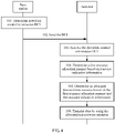
- FIG. 4 is a schematic flowchart of a resource allocation method according to an embodiment of the present invention. As shown in FIG. 4 , this embodiment of the present invention is described by using an example in which a second node is a base station, and a first node is a terminal. The method includes step 101 to step 106. For a specific process, refer to the following detailed description.
- the base station determines downlink control information (DCI).
- DCI downlink control information
- the DCI includes resource indication information
- the resource indication information is used to determine a first resource allocation manner and an allocated transmission resource for the terminal
- the first resource allocation manner is used to allocate a transmission resource greater than one narrowband (NB).
- NB narrowband
- the base station may determine, based on a resource requirement of the terminal, a resource that needs to be allocated to the terminal.
- a system bandwidth of the base station includes a plurality of resource block groups (resource block group, RBG), and each RBG includes at least one RB.
- RBG resource block group
- a quantity of RBs included in one RBG may be 2, 3, or 4.
- One NB includes six RBs.
- the base station determines to allocate the transmission resource greater than one NB to the terminal, the base station determines that a resource allocation manner is the first resource allocation manner, and further determines the resource indication information corresponding to the allocated transmission resource.
- a field included in the resource indication information, a bit location of the included field in the DCI, the allocated transmission resource, and a bit state of the included field are consistent in the terminal and in the base station sending the DCI to the terminal, so that the terminal can correctly interpret the resource indication information in the DCI after the base station sends the DCI including the resource indication information.
- the resource indication information includes a first field.
- the base station determines to use the first resource allocation manner, and sets a value of the first field included in the resource indication information to be within a range of a first state set.
- the terminal may determine, by performing determining on the first field, that a transmission resource allocation manner is the first resource allocation manner.
- a quantity of binary bits of the first field is 5, and the first state set includes a 5-bit binary value corresponding to a positive integer within an interval range [21, 31].
- the first state set herein includes a 5-bit binary value corresponding to 21 and that corresponding to 31.
- the resource indication information includes a second field including Z binary bits, and Z is a positive integer.
- the base station and the terminal may determine that a transmission resource allocation manner is the first resource allocation manner.
- a quantity of binary bits of the second field is 2.
- the quantity of binary bits included in the second field and a bit state corresponding to the first resource allocation manner are not limited in this embodiment of the present invention.
- the resource indication information includes a third field.
- the base station and the terminal may preset a quantity of bits included in the third field and a bit state that are corresponding to the first resource allocation manner. For example, if the third field is a first preset value, it is determined that a transmission resource allocation manner is the first resource allocation manner.
- the base station sends the DCI to the terminal.
- the base station sends the DCI to the terminal.
- the base station may send the DCI by using an existing DCI format.
- the DCI format is a DCI format 6-0A or a DCI format 6-1A.
- the base station may send the DCI by using a newly defined DCI format. This is not limited in this embodiment of the present invention.
- the terminal receives the DCI from the base station, where the DCI includes resource indication information, and the resource indication information is used to indicate a transmission resource allocation manner.
- the terminal determines a first resource allocation manner based on the resource indication information.
- the terminal determines an allocated transmission resource based on the first resource allocation manner and the resource indication information.
- the terminal transmits data by using the allocated transmission resource.
- the terminal may determine the transmission resource allocation manner by using the resource indication information.
- the transmission resource allocation manner includes the first resource allocation manner, and the first resource allocation manner is used to allocate the transmission resource greater than one NB.
- the transmission resource greater than one NB can be allocated, and a quantity of RBs allocated to the terminal is increased.
- a terminal that can support a relatively large bandwidth can also transmit data by using a transmission resource greater than one NB
- the resource indication information includes the first field and a fourth field.
- the terminal receives the DCI including the resource indication information, and determines, by using the first field, that the transmission resource allocation manner is the first resource allocation manner, the terminal determines a resource indicator value based on the first field and the fourth field, and searches for one or more corresponding target RBGs based on the determined resource indicator value.
- the resource indicator value is used to indicate a start RBG and a quantity of consecutive RBGs starting from the start RBG
- a correspondence between the resource indicator value and the one or more target RBGs is preset, and may be set by the base station and notified to the terminal, or may be determined by the base station and the terminal through negotiation.
- the terminal determines a resource indicator value based on the first field and the fourth field may be specifically: calculating, by the terminal, a first intermediate indicator value based on the first field and the fourth field by using a first calculation formula; and determining, based on a preset first mapping relationship, a resource indicator value corresponding to the first intermediate indicator value.
- a unique first intermediate indicator value may be determined based on the first field and the fourth field, and then a unique resource indicator value may be determined based on the first intermediate indicator value, so that one or more corresponding target RBGs can be found by using the determined unique resource indicator value.
- the foregoing description is merely an example, and a manner of determining a unique resource indicator value based on the first field and the fourth field is not limited in this embodiment of the present invention.
- the resource indication information includes the third field and a fifth field.
- the terminal receives the DCI including the resource indication information, and determines, by using the third field, that the transmission resource allocation manner is the first resource allocation manner, the terminal determines a resource indicator value based on the third field and the fifth field, and searches for one or more corresponding target RBGs based on the determined resource indicator value.
- the resource indicator value is used to indicate a start RBG and a quantity of consecutive RBGs starting from the start RBG
- a correspondence between the resource indicator value and the one or more target RBGs is preset, and may be set by the base station and notified to the terminal, or may be determined by the base station and the terminal through negotiation.
- the terminal determines a resource indicator value based on the third field and the fifth field may be specifically: calculating, by the terminal, a second intermediate indicator value based on the fifth field by using a second calculation formula; and determining, based on a preset second mapping relationship, a resource indicator value corresponding to the second intermediate indicator value.
- a unique second intermediate indicator value may be determined based on the fifth field, and then a unique resource indicator value may be determined based on the second intermediate indicator value, so that one or more corresponding target RBGs can be found by using the determined unique resource indicator value.
- the foregoing description is merely an example, and a manner of determining a unique resource indicator value based on the fifth field is not limited in this embodiment of the present invention.
- the resource indication information includes the second field and a sixth field.
- the terminal receives the DCI including the resource indication information, and determines, by using the second field, that the transmission resource allocation manner is the first resource allocation manner, the terminal determines a resource indicator value based on the sixth field, and searches for one or more corresponding target RBGs based on the determined resource indicator value.
- the resource indicator value is used to indicate a start RBG and a quantity of consecutive RBGs starting from the start RBG A correspondence between the resource indicator value and the one or more target RBGs is preset, and may be set by the base station and notified to the terminal, or may be determined by the base station and the terminal through negotiation.
- the terminal determines a resource indicator value based on the sixth field may be specifically: calculating, by the terminal, a third intermediate indicator value based on the sixth field by using a third calculation formula; and determining, based on a preset third mapping relationship, a resource indicator value corresponding to the third intermediate indicator value.
- a unique third intermediate indicator value may be determined based on the sixth field, and then a unique resource indicator value may be determined based on the third intermediate indicator value, so that one or more corresponding target RBGs can be found by using the determined unique resource indicator value.
- the foregoing description is merely an example, and a manner of determining a unique resource indicator value based on the sixth field is not limited in this embodiment of the present invention.
- determining the DCI by the base station may be determining the resource allocation manner, the field in the DCI, and the bit state included in the field based on a reverse process of interpreting the DCI by the terminal.
- the base station determines, based on a current resource requirement and the maximum bandwidth that can be supported by the terminal, the transmission resource allocated to the terminal, that is, determines the allocated start RBG and the quantity of consecutive RBGs starting from the start RBG. Then, the base station determines the resource indicator value of the allocated transmission resource, for example, may search a correspondence between the RIV and the start RBG and the quantity of consecutive RBGs starting from the start RBG for the RIV corresponding to the allocated transmission resource. Finally, the base station determines the resource indication information in the DCI based on the RIV, and sends the DCI including the resource indication information to the terminal.
- determining the resource indication information in the DCI by the base station based on the RIV may be a reverse process of determining the RIV by the terminal based on the resource indication information. For example, when the resource indication information includes the first field and the fourth field, if the base station allocates the transmission resource greater than one NB to the terminal, the base station determines the first intermediate indicator value based on the RIV, and determines binary values of the first field and the fourth field based on the first intermediate indicator value, that is, determines the resource indicator value.
- the base station may determine the resource indication information based on the RIV according to a reverse process of determining the RIV by the terminal in another manner. This is not limited in this embodiment of the present invention.
- the terminal receives, from the base station, the DCI including the resource indication information, and determines, based on the resource indication information, the first resource allocation manner used to allocate the transmission resource greater than one narrowband (NB); and the terminal determines the allocated transmission resource based on the first resource allocation manner and the resource indication information, and transmits the data by using the allocated transmission resource.
- the transmission resource greater than one NB is allocated, and a quantity of RBs allocated to the terminal is increased.
- FIG. 5 is a schematic flowchart of another resource allocation method according to an embodiment of the present invention. As shown in FIG. 5 , this embodiment of the present invention is described by using an example in which a first node is a terminal, and a second node is a base station. The method includes step 201 to step 206. For a specific process, refer to the following detailed description.
- the base station determines downlink control information (DCI).
- DCI downlink control information
- the base station sends the DCI to the terminal.
- the terminal receives the DCI from the base station, where the DCI includes resource indication information, and the resource indication information is used to indicate a transmission resource allocation manner.
- the terminal determines, based on the resource indication information, that a resource allocation manner of allocating a transmission resource is a first resource allocation manner, determine an allocated transmission resource based on the first resource allocation manner and the resource indication information.
- the terminal determines, based on the resource indication information, that a resource allocation manner of allocating a transmission resource is a second resource allocation manner, determine an allocated transmission resource based on the second resource allocation manner and the resource indication information.
- the terminal transmits data by using the allocated transmission resource.
- the first resource allocation manner is used to allocate a transmission resource greater than one NB
- the second resource allocation manner is used to allocate a transmission resource less than or equal to one NB
- the resource indication information may be used to indicate the transmission resource allocation manner.
- the resource indication information is used to indicate that the transmission resource allocation manner is the first resource allocation manner
- the resource indication information is used to indicate that the transmission resource allocation manner is the second resource allocation manner.
- the terminal may interpret the DCI to determine the transmission resource allocation manner based on the resource indication information, and determine the allocated transmission resource, so as to transmit the data by using the allocated transmission resource.
- transmitting the data herein may be receiving the data or sending the data, which is determined based on the transmission resource allocated by the base station. If the base station allocates an uplink transmission resource, the terminal sends the data by using the allocated uplink transmission resource. If the base station allocates a downlink transmission resource, the terminal receives the data by using the allocated downlink transmission resource.
- the resource indication information includes a first field and a fourth field. If a value of the first field belongs to a first state set, the terminal determines that the transmission resource allocation manner is the first resource allocation manner. If the value of the first field belongs to a second state set, the terminal determines that the transmission resource allocation manner is the second resource allocation manner.
- bit locations of the first field and the fourth field may be bit locations included in the existing DCI. In this way, the transmission resource greater than one NB can be allocated without increasing bit overheads, so as to enhance effective utilization of each bit in the DCI.
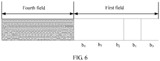
- FIG. 6 is an example diagram of resource allocation in a DCI format according to an embodiment of the present invention. It can be learned that a quantity of binary bits of the first field is 5, that is, b 4 b 3 b 2 b 1 b 0 , which is the same as a quantity of bits used for resource allocation in an existing technical solution. Because 21 bit states are used in the existing technical solution to allocate a transmission resource in the second resource allocation manner, the remaining 11 bit states may be used for the first resource allocation manner. Optionally, bit states of b 4 b 3 b 2 b 1 b 0 are divided into 21 bit states and 11 bit states, which are respectively corresponding to the second state set and the first state set.
- the first state set includes a 5-bit binary value corresponding to a positive integer within an interval range [21, 31].
- the second state set includes a 5-bit binary value corresponding to a positive integer within an interval range [0, 20].
- the first state set includes a bit state corresponding to 21 and a bit state corresponding to 31, and the second state set includes a bit state corresponding to 0 and a bit state corresponding to 20.
- Bit state division of b 4 b 3 b 2 b 1 b 0 is not limited in this embodiment of the present invention.
- the fourth field includes ⁇ log 2 ⁇ N RB UL 6 ⁇ ⁇ ( ⁇ log 2 ⁇ N RB DL 6 ⁇ ⁇ in downlink) bits.
- the existing technical solution may be used, that is, an NB index of an NB may be determined based on the fourth field, and a resource indicator value may be determined based on a binary number of b 4 b 3 b 2 b 1 b 0 , so as to determine the allocated transmission resource.
- a first intermediate indicator value is calculated according to a first calculation formula, the ⁇ log 2 ⁇ N RB UL 6 ⁇ ⁇ ( ⁇ log 2 ⁇ N RB DL 6 ⁇ ⁇ in downlink) bits included in the fourth field, and b 4 b 3 b 2 b 1 b 0 included in the first field, and a resource indicator value corresponding to the first intermediate indicator value is determined based on a preset first mapping relationship. It can be understood that a larger quantity of used bits indicates more included bit states, and therefore the allocated transmission resource is indicated by using the fourth field and the first field jointly, so as to indicate allocation of more transmission resources.
- the first calculation formula herein is an optional formula, and the first calculation formula is not limited in this embodiment of the present invention.
- a system bandwidth may be 20 MHz, 15 MHz, 10 MHz, 5 MHz, 3 MHz, or the like, and a maximum bandwidth that can be supported by the terminal may be 20 MHz, 5 MH, or the like.
- different first mapping relationships between different first intermediate indicator values and different resource indicator values may be set, to implement a one-to-one correspondence between the first intermediate indicator values and the resource indicator values.
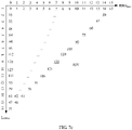
- FIG. 7a is an example diagram of an RBG in a 20 MHz bandwidth according to an embodiment of the present invention.
- a transmission resource within one NB is allocated in the second resource allocation manner.
- FIG. 7b is an example diagram of a state of an RBG according to an embodiment of the present invention.
- a quantity ⁇ log 2 ⁇ N RB UL 6 ⁇ ⁇ ( ⁇ log 2 ⁇ N RB DL 6 ⁇ ⁇ in downlink) of binary bits included in the fourth field is 4, and the first intermediate indicator value determined according to the first calculation formula totally includes 176 states. Therefore, a value range of the first intermediate indicator value is enough to support 120 possibilities.
- the first intermediate indicator value ranges from 0 to 119 (including 0 and 119).
- the first mapping relationship needs to ensure that the first intermediate indicator values are in a one-to-one correspondence with the RIVs, and the first mapping relationship is not limited in this embodiment of the present invention. For example, if a value of the RIV starts from 0, and the transmission resource less than or equal to one NB is determined in the second resource allocation manner, one RBG is equivalent to one NB. Therefore, one consecutive RBG starting from a start RBG does not need to be indicated by using the first resource allocation manner. Therefore, referring to FIG. 7c, FIG.
- FIG. 7c is another example diagram of RB allocation corresponding to an RIV according to an embodiment of the present invention.
- a value of each RIV is corresponding to a unique start RBG and a unique quantity of consecutive RBGs starting from the start RBG.
- a range of the RIV is [16, 135].
- the one-to-one correspondence between the resource indicator values and the first intermediate indicator values may be established by using the foregoing method.
- the base station After determining to allocate the transmission resource to the terminal, and determining that the transmission resource allocation manner is the first resource allocation manner, the base station determines, based on the to-be-allocated transmission resource, the bit states corresponding to the first field and the fourth field in the DCI.
- the terminal receives the DCI, obtains the first intermediate indicator value through calculation based on the bit states corresponding to the first field and the fourth field, determines, based on the first mapping relationship, the RIV corresponding to the first intermediate indicator value, and determines, based on the RIV, the start RBG for resource allocation and the quantity of consecutive RBGs starting from the start RBG, so as to determine the transmission resource allocated by the base station.
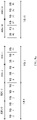
- FIG. 8a is another example diagram of an RBG in a 20 MHz bandwidth according to an embodiment of the present invention.
- a transmission resource within one NB is allocated in the second resource allocation manner. Therefore, when the transmission resource is allocated in the first resource allocation manner, only allocation of a resource greater than one NB may be indicated.
- FIG. 8b is another example diagram of a state of an RBG according to an embodiment of the present invention. Further, because the system bandwidth is 20
- a quantity ⁇ log 2 ⁇ N RB UL 6 ⁇ ⁇ ( ⁇ log 2 ⁇ N RB DL 6 ⁇ ⁇ in downlink) of binary bits included in the fourth field is 4, and the first intermediate indicator value determined according to the first calculation formula totally includes 176 states. Therefore, a value range of the first intermediate indicator value is enough to support 165 possibilities.
- the first intermediate indicator value ranges from 0 to 164 (including 0 and 164).
- i 1 and j 1 are integer intermediate variables. Specifically, after the first intermediate indicator value is calculated, i 1 and j 1 are calculated based on the first intermediate indicator value, and the resource indicator value is calculated based on the first intermediate indicator value, i 1 , and j 1 .
- the foregoing formula may be represented by Table 1, which is shown in Table 1. It can be learned that by using the foregoing formula, i 1 and j 1 may be corresponding to a quantity of consecutive RBGs, and the first intermediate indicator values may be in a one-to-one correspondence with the resource indicator values.
- RIV represents the resource indicator value
- Offset ( X 1 ) represents a predefined offset of the resource indicator value RIV relative to the first intermediate indicator value X 1 .
- an offset may be specified for first intermediate indicator values in different ranges, and it is ensured that the first intermediate indicator values are in a one-to-one correspondence with the RIVs.
- An offset indicated by a first intermediate indicator value in each range is not limited in this embodiment of the present invention.
- Table 2 provides a possible correspondence between a first intermediate indicator value and an RIV.
- Table 2 Quantity of Consecutive RBGs Quantity of States X 1 RIV Offset ( X 1 ) 3 30 0 to 29 64 to 93 64 4 29 30 to 58 96 to 124 66 5 28 59 to 86 128 to 155 69 6 27 87 to 113 160 to 186 73 7 26 114 to 139 192 to 217 78 8 25 140 to 164 224 to 248 84
- the one-to-one correspondence between the resource indicator values and the first intermediate indicator values may be established by using the foregoing method.
- the base station After determining to allocate the transmission resource to the terminal, and determining that the resource allocation manner is the first resource allocation manner, the base station determines, based on the to-be-allocated transmission resource, the bit states corresponding to the first field and the fourth field in the DCI.
- the terminal receives the DCI, obtains the first intermediate indicator value through calculation based on the bit states corresponding to the first field and the fourth field, determines, based on the first mapping relationship, the RIV corresponding to the first intermediate indicator value, and determines, based on the RIV, the start RBG for resource allocation and the quantity of consecutive RBGs starting from the start RBG, so as to determine the transmission resource allocated by the base station.
- Table 3 is a table of a possible resource allocation situation in the first resource allocation manner according to an embodiment of the present invention.
- the maximum bandwidth that can be supported by the terminal is 20 MHz
- a quantity of states that can be indicated by the first intermediate indicator value is enough to indicate resource allocation states when the RBG includes six consecutive RBs.
- the system bandwidth is 15 MHz, and it may be determined, according to a calculation formula of the first intermediate indicator value, that a maximum quantity of available states of the first intermediate indicator value is 176.
- a quantity of resource allocation states that need to be considered in the first resource allocation manner is 120, and a specific quantity of allocated consecutive RBGs is 2 to 16.
- resource allocation may be indicated by using a method similar to the method used when the system bandwidth is 20 MHz.
- a mark "N/A" indicates that for a corresponding system bandwidth and a corresponding quantity of RBs included in one RBG, the first intermediate indicator value cannot be used for allocation, and the corresponding maximum quantity of available states of the first intermediate indicator value is exceeded.
- Table 4 is a table of another possible resource allocation situation in the first resource allocation manner according to an embodiment of the present invention.
- the maximum bandwidth that can be supported by the terminal is 5 MHz
- a quantity of states that can be indicated by the first intermediate indicator value is enough to indicate resource allocation states when the RBG includes three consecutive RBs. Therefore, in different system bandwidths, resource allocation may be indicated by using a method similar to the method used when the system bandwidth is 20 MHz.
- resource allocation may be indicated by using a method similar to the method used when the system bandwidth is 20 MHz.
- the resource indication information includes a second field and a sixth field. Specifically, whether the transmission resource is allocated in the first resource allocation manner or the second resource allocation manner may be determined by using a bit state in the second field.
- the second field includes Z binary bits, and Z is a positive integer.
- bit locations of the second field and the sixth field may be bit locations included in the existing DCI. In this way, the transmission resource greater than one NB can be allocated without increasing bit overheads, so as to enhance effective utilization of each bit in the DCI.
- FIG. 9 is an example diagram of resource allocation in a DCI format according to an embodiment of the present invention. It can be learned that a quantity of binary bits of the second field is 2, and two most significant bits in the last five bits in the existing technical solution are selected, that is, b 4 b 3 . In the existing technical solution, 21 bit states are used for the second resource allocation manner, and 21 states of b 4 b 3 b 2 b 1 b 0 from '00000' to '10100' are used. Therefore, allocation states of '10101' to '11111' cannot occur, that is, a state of '11xxx ' cannot occur.
- whether the transmission resource is allocated in the first resource allocation manner or the second resource allocation manner may be determined by using b 4 b 3 . If states of bit locations of b 4 b 3 are both 1, it is determined that the transmission resource is allocated in the first resource allocation manner. If at least one of the states of the bit locations of b 4 b 3 is 0, it is determined that the transmission resource is allocated in the second resource allocation manner.
- Bit state division of b 4 b 3 is not limited in this embodiment of the present invention.
- the sixth field includes a third sub-field and a fourth sub-field, the fourth sub-field includes bits b 2 b 1 b 0 , and the third sub-field includes ⁇ log 2 ⁇ N RB UL 6 ⁇ ⁇ ( ⁇ log 2 ⁇ N RB DL 6 ⁇ ⁇ in downlink) bits.
- the existing technical solution may be used, that is, an NB index of an NB may be determined based on the third sub-field, and a resource indicator value may be determined based on a binary number of b 4 b 3 b 2 b 1 b 0 , so as to determine the allocated transmission resource.
- a third intermediate indicator value is calculated according to a third calculation formula and the third sub-field and the fourth sub-field that are included in the sixth field, and a resource indicator value corresponding to the third intermediate indicator value is determined based on a preset third mapping relationship.
- the third intermediate indicator value calculated in this manner can reflect all bit states included in the third sub-field and the fourth sub-field, a minimum value of the third intermediate indicator value may be 0, and the third intermediate indicator value may range between consecutive integers.
- the third calculation formula herein is an optional formula, and the third calculation formula is not limited in this embodiment of the present invention.
- a system bandwidth may be 20 MHz, 15 MHz, 10 MHz, 5 MHz, 3 MHz, or the like, and a maximum bandwidth that can be supported by the terminal may be 20 MHz, 5 MH, or the like.
- different third mapping relationships between different third intermediate indicator values and different resource indicator values may be set, to implement a one-to-one correspondence between the third intermediate indicator values and the resource indicator values.
- the system bandwidth is 20 MHz
- the maximum bandwidth that can be supported by the terminal is 20 MHz (20 MHz is corresponding to 16 NBs, one NB includes six RBs, and therefore there are totally 96 RBs)
- one RBG is set to include six consecutive RBs.
- the quantity of resource allocation states in the first resource allocation manner is 120.
- a quantity of binary bits included in the third sub-field is 4, and the third intermediate indicator value determined according to the third calculation formula includes 128 states. Therefore, a value range of the third intermediate indicator value is enough to support 120 possibilities.
- the third intermediate indicator value ranges from 0 to 119 (including 0 and 119).
- the third mapping relationship needs to ensure that the third intermediate indicator values are in a one-to-one correspondence with the RIVs, and the third mapping relationship is not limited in this embodiment of the present invention.
- the one-to-one correspondence between the resource indicator values and the third intermediate indicator values may be established by using the foregoing method.
- the base station After determining to allocate the transmission resource to the terminal, and determining that the resource allocation manner is the first resource allocation manner, the base station determines, based on the to-be-allocated transmission resource, the bit states corresponding to the second field and the sixth field in the DCI.
- the terminal receives the DCI, determines the first resource allocation manner based on the second field, obtains the third intermediate indicator value through calculation based on the bit state corresponding to the sixth field, determines, based on the third mapping relationship, the RIV corresponding to the third intermediate indicator value, and determines, based on the RIV, the start RBG for resource allocation and the quantity of consecutive RBGs starting from the start RBG, so as to determine the transmission resource allocated by the base station.
- one RBG is set to include three consecutive RBs.
- the first resource allocation manner only a scenario in which three RBGs, four RBGs, ..., or eight RBGs are allocated needs to be considered.
- the quantity of resource allocation states in the first resource allocation manner is 84 (15 + 15 + 14 + 14 + 13 + 13). Because the system bandwidth is 20 MHz, a quantity of binary bits included in the third sub-field is 4, and the third intermediate indicator value determined according to the third calculation formula includes 128 states. Therefore, a value range of the third intermediate indicator value is enough to support 84 possibilities.
- the third intermediate indicator value ranges from 0 to 83 (including 0 and 83).
- i 3 and j 3 are integer intermediate variables, as shown in Table 5. It can be learned that by using the foregoing formula, i 3 and j 3 may be corresponding to a quantity of consecutive RBGs, and the third intermediate indicator values may be in a one-to-one correspondence with the resource indicator values.
- RIV represents the resource indicator value
- Offset ( X 3 ) represents a predefined offset of the resource indicator value RIV relative to the third intermediate indicator value X 3 .
- an offset may be specified for third intermediate indicator values in different ranges, and it is ensured that the third intermediate indicator values are in a one-to-one correspondence with the RIVs.
- An offset indicated by a third intermediate indicator value in each range is not limited in this embodiment of the present invention.
- Table 6 provides a possible correspondence between a third intermediate indicator value and an RIV.
- Table 6 Quantity of Consecutive RBGs Quantity of States X 3 RIV Offset ( X 3 ) 3 15 0 to 14 64, 66, ..., 90, 92 64 4 15 15 to 29 96, 98, ..., 122, 124 66 5 14 30 to 43 128, 130, ..., 152, 154 68 6 14 44 to 57 160, 162, ..., 184, 186 72 7 13 58 to 70 192, 194, ..., 214, 216 76 8 13 71 to 83 224, 226, ...,246, 248 82
- the one-to-one correspondence between the resource indicator values and the third intermediate indicator values may be established by using the foregoing method.
- the base station After determining to allocate the transmission resource to the terminal, and determining that the resource allocation manner is the first resource allocation manner, the base station determines, based on the to-be-allocated transmission resource, the bit states corresponding to the second field and the sixth field in the DCI.
- the terminal receives the DCI, determines the first resource allocation manner based on the second field, obtains the third intermediate indicator value through calculation based on the bit state corresponding to the sixth field, determines, based on the third mapping relationship, the RIV corresponding to the third intermediate indicator value, and determines, based on the RIV, the start RBG for resource allocation and the quantity of consecutive RBGs starting from the start RBG, so as to determine the transmission resource allocated by the base station.
- Table 7 is a table of a possible resource allocation situation in the first resource allocation manner according to an embodiment of the present invention.
- the maximum bandwidth that can be supported by the terminal is 20 MHz
- a quantity of states that can be indicated by the third intermediate indicator value is enough to indicate resource allocation states when the RBG includes six consecutive RBs.
- the system bandwidth is 10 MHz, and it may be determined, according to a calculation formula of the third intermediate indicator value, that a maximum quantity of available states of the third intermediate indicator value is 64.
- a maximum quantity of available states of the third intermediate indicator value is 64.
- resource allocation may be indicated by using a method similar to the method used when the system bandwidth is 20 MHz.
- a mark "N/A" indicates that for a corresponding system bandwidth and a corresponding quantity of RBs included in one RBG, the third intermediate indicator value cannot be used for allocation, and the corresponding maximum quantity of available states of the third intermediate indicator value is exceeded.
- Table 8 is a table of another possible resource allocation situation in the first resource allocation manner according to an embodiment of the present invention.
- the maximum bandwidth that can be supported by the terminal is 5 MHz
- a quantity of states that can be indicated by the third intermediate indicator value is enough to indicate resource allocation states when the RBG includes six consecutive RBs. Therefore, in different system bandwidths, resource allocation may be indicated by using a method similar to the method used when the system bandwidth is 20 MHz.
- resource allocation in the system bandwidths of 20 MHz and 10 MHz may be limited (an index number of the included RBG starts from 0, and an index number of the start RBG for resource allocation is an even number).
- the third intermediate indicator value may be used to indicate all possibilities of resource allocation when the RBG includes three consecutive RBs. Therefore, resource allocation may be indicated by using a method similar to the method used when the system bandwidth is 20 MHz. For example, the system bandwidth is 20 MHz, and it may be determined, according to a calculation formula of the third intermediate indicator value, that a maximum quantity of available states of the third intermediate indicator value is 128. When one RBG includes three RBs, a quantity of resource allocation states that need to be considered in the first resource allocation manner is 165, and a specific quantity of allocated consecutive RBGs is 3 to 8.
- resource allocation may be still indicated by using a method similar to the method used when the system bandwidth is 20 MHz.
- the resource indication information includes a third field and a fifth field. Specifically, whether the transmission resource is allocated in the first resource allocation manner or the second resource allocation manner may be determined by using a bit state in the third field.
- the third field includes one binary bit.
- a bit location of the third field may be additionally added. In this way, the transmission resource greater than one NB can be allocated when one bit is added, so as to enhance effective utilization of each bit in the DCI.
- FIG. 10 is an example diagram of resource allocation in another DCI format according to an embodiment of the present invention. It can be learned that a quantity of binary bits of the third field is 1, and the last five bits and ⁇ log 2 ⁇ N RB UL 6 ⁇ ⁇ ( ⁇ log 2 ⁇ N RB DL 6 ⁇ ⁇ in downlink) bits in the existing technical solution are further included. If the bit state of the third field is 1, it is determined that the transmission resource is allocated in the first resource allocation manner; if the bit state of the third field is 0, it is determined that the transmission resource is allocated in the second resource allocation manner.
- bit state of the third field is 0, it is determined that the transmission resource is allocated in the first resource allocation manner; if the bit state of the third field is 1, it is determined that the transmission resource is allocated in the second resource allocation manner. This is not limited in this embodiment of the present invention.
- the fifth field includes a first sub-field and a second sub-field
- the second sub-field includes the bits b 4 b 3 b 2 b 1 b 0
- the first sub-field includes ⁇ log 2 ⁇ N RB UL 6 ⁇ ⁇ ( ⁇ log 2 ⁇ N RB DL 6 ⁇ ⁇ in downlink) bits.
- the existing technical solution may be used, that is, an NB index of an NB may be determined based on the first sub-field, and a resource indicator value may be determined based on a binary number of b 4 b 3 b 2 b 1 b 0 , so as to determine the allocated transmission resource.
- a second intermediate indicator value is calculated according to a second calculation formula and the first sub-field and the second sub-field that are included in the fifth field, and a resource indicator value corresponding to the second intermediate indicator value is determined based on a preset second mapping relationship.
- the second intermediate indicator value calculated in this manner can reflect all bit states included in the first sub-field and the second sub-field, a minimum value of the second intermediate indicator value may be 0, and the second intermediate indicator value may range between consecutive integers.
- the second calculation formula herein is an optional formula, and the second calculation formula is not limited in this embodiment of the present invention.
- a system bandwidth may be 20 MHz, 15 MHz, 10 MHz, 5 MHz, 3 MHz, or the like, and a maximum bandwidth that can be supported by the terminal may be 20 MHz, 5 MH, or the like.
- different second mapping relationships between different second intermediate indicator values and different resource indicator values may be set, to implement a one-to-one correspondence between the second intermediate indicator values and the resource indicator values.
- the system bandwidth is 20 MHz
- the maximum bandwidth that can be supported by the terminal is 20 MHz (20 MHz is corresponding to 16 NBs, one NB includes six RBs, and therefore there are totally 96 RBs
- one RBG is set to include three consecutive RBs.
- the quantity of resource allocation states in the first resource allocation manner is 465.
- the second intermediate indicator value determined according to the second calculation formula includes 512 states. Therefore, a value range of the second intermediate indicator value is enough to support 465 possibilities.
- the second intermediate indicator value ranges from 0 to 464 (including 0 and 464).
- the second mapping relationship needs to ensure that the second intermediate indicator values are in a one-to-one correspondence with the RIVs, and the second mapping relationship is not limited in this embodiment of the present invention.
- the one-to-one correspondence between the resource indicator values and the second intermediate indicator values may be established by using the foregoing method.
- the base station After determining to allocate the transmission resource to the terminal, and determining that the resource allocation manner is the first resource allocation manner, the base station determines, based on the to-be-allocated transmission resource, the bit states corresponding to the third field and the fifth field in the DCI.
- the terminal receives the DCI, determines the first resource allocation manner based on the third field, obtains the second intermediate indicator value through calculation based on the bit state corresponding to the fifth field, determines, based on the second mapping relationship, the RIV corresponding to the second intermediate indicator value, and determines, based on the RIV, the start RBG for resource allocation and the quantity of consecutive RBGs starting from the start RBG, so as to determine the transmission resource allocated by the base station.
- the system bandwidth is 20 MHz
- the maximum bandwidth that can be supported by the terminal is 5 MHz
- 5 MHz is corresponding to eight NBs, and there are totally 24 RBs
- one RBG is set to include two consecutive RBs.
- the quantity of resource allocation states in the first resource allocation manner is 369 (45 + 44 + ... + 37).
- the second intermediate indicator value determined according to the second calculation formula includes 512 states. Therefore, a value range of the second intermediate indicator value is enough to support 369 possibilities.
- the second intermediate indicator value ranges from 0 to 368 (including 0 and 368).
- i 2 and j 2 are integer intermediate variables, as shown in Table 9. It can be learned that by using the foregoing formula, i 2 and j 2 may be corresponding to a quantity of consecutive RBGs, and the second intermediate indicator values may be in a one-to-one correspondence with the resource indicator values.
- RIV represents the resource indicator value
- Offset ( X 2 ) represents a predefined offset of the resource indicator value RIV relative to the second intermediate indicator value X 2 .
- an offset may be specified for second intermediate indicator values in different ranges, and it is ensured that the second intermediate indicator values are in a one-to-one correspondence with the RIVs.
- An offset indicated by a second intermediate indicator value in each range is not limited in this embodiment of the present invention.
- Table 10 provides a possible correspondence between a second intermediate indicator value and an RIV.
- Table 10 Quantity of Consecutive RBGs Quantity of States X 2 RIV Offset ( X 2 ) 4 45 0 to 44 144 to 188 144 5 44 45 to 88 192 to 235 147 6 43 89 to 131 240 to 282 151 7 42 132 to 173 288 to 329 156 8 41 174 to 214 336 to 376 162 9 40 215 to 254 384 to 423 169 10 39 255 to 293 432 to 470 177 11 38 294 to 331 480 to 517 186 12 37 332 to 368 528 to 564 196
- the one-to-one correspondence between the resource indicator values and the second intermediate indicator values may be established by using the foregoing method.
- the base station After determining to allocate the transmission resource to the terminal, and determining that the resource allocation manner is the first resource allocation manner, the base station determines, based on the to-be-allocated transmission resource, the bit states corresponding to the third field and the fifth field in the DCI.
- the terminal receives the DCI, determines the first resource allocation manner based on the third field, obtains the second intermediate indicator value through calculation based on the bit state corresponding to the fifth field, determines, based on the second mapping relationship, the RIV corresponding to the second intermediate indicator value, and determines, based on the RIV, the start RBG for resource allocation and the quantity of consecutive RBGs starting from the start RBG, so as to determine the transmission resource allocated by the base station.
- RBGs including different quantities of RBs, and different maximum bandwidths supported by the terminal
- a maximum quantity of available states of the determined second intermediate indicator value is different
- a quantity of RBGs that can be allocated in the first resource allocation manner is different.
- Table 11 is a table of a possible resource allocation situation in the first resource allocation manner according to an embodiment of the present invention.
- the maximum bandwidth that can be supported by the terminal is 20 MHz
- a quantity of states that can be indicated by the second intermediate indicator value is enough to indicate resource allocation states when the RBG includes three consecutive RBs. Therefore, in different system bandwidths, resource allocation may be indicated by using a method similar to the method used when the system bandwidth is 20 MHz.
- Table 12 is a table of another possible resource allocation situation in the first resource allocation manner according to an embodiment of the present invention.
- the maximum bandwidth that can be supported by the terminal is 5 MHz
- a quantity of states that can be indicated by the second intermediate indicator value is enough to indicate resource allocation states when the RBG includes two consecutive RBs. Therefore, in different system bandwidths, resource allocation may be indicated by using a method similar to the method used when the system bandwidth is 20 MHz.
- determining the DCI by the base station may be determining the resource allocation manner, the field in the DCI, and content in the field based on a reverse process of interpreting the DCI by the terminal.
- the base station determines, based on a current resource requirement and the maximum bandwidth that can be supported by the terminal, the transmission resource allocated to the terminal, that is, determines the allocated start RBG and the quantity of consecutive RBGs starting from the start RBG. Then, the base station determines the resource indicator value of the allocated transmission resource, for example, may search a correspondence between the RIV and the start RBG and the quantity of consecutive RBGs starting from the start RBG for the RIV corresponding to the allocated transmission resource. Finally, the base station determines the resource indication information in the DCI based on the RIV, and sends the DCI including the resource indication information to the terminal.
- determining the resource indication information in the DCI by the base station based on the RIV may be a reverse process of determining the RIV by the terminal based on the resource indication information. For example, when the resource indication information includes the first field and the fourth field, if the base station allocates the transmission resource greater than one NB to the terminal, the base station determines the first intermediate indicator value based on the RIV, and determines binary values of the first field and the fourth field based on the first intermediate indicator value, that is, determines the resource indicator value.
- the base station may determine the resource indication information based on the RIV according to a reverse process of determining the RIV by the terminal in another manner. This is not limited in this embodiment of the present invention.
- the terminal receives, from the base station, the DCI including the resource indication information, and determines, based on the resource indication information, the first resource allocation manner used to allocate the transmission resource greater than one narrowband (NB) and the second resource allocation manner used to allocate the transmission resource less than or equal to one NB.
- the terminal determines the allocated transmission resource based on the determined transmission resource allocation manner and the resource indication information, and transmits the data by using the allocated transmission resource. In this way, the transmission resource greater than one NB and the transmission resource less than or equal to one NB can be allocated, improving flexibility of transmission resource allocation.
- FIG. 11 is a schematic structural diagram of a first node according to an embodiment of the present invention.
- the first node in this embodiment of the present invention may be the first node provided in any one of the embodiments shown in FIG. 4 to FIG. 10 .
- a first node 1 in this embodiment of the present invention may include a receiving module 11, a determining module 12, and a transmission module 13.
- the receiving module 11 is configured to receive downlink control information (DCI) from a second node, where the DCI includes resource indication information, and the resource indication information is used to indicate a transmission resource allocation manner.
- DCI downlink control information
- the determining module 12 is configured to determine a first resource allocation manner based on the resource indication information, where the first resource allocation manner is used to allocate a transmission resource greater than one narrowband (NB).
- NB narrowband
- the determining module 12 is further configured to determine an allocated transmission resource based on the first resource allocation manner and the resource indication information.
- the transmission module 13 is configured to transmit data by using the allocated transmission resource.
- the resource indication information includes a first field; and that the determining module is configured to determine a first resource allocation manner based on the resource indication information is specifically: when a value of the first field belongs to a first state set, determining the first resource allocation manner.
- a quantity of binary bits of the first field is 5; and the first state set includes a 5-bit binary value corresponding to a positive integer within an interval range [21, 31].
- a system bandwidth of the second node includes a plurality of resource block groups (RBGs), and each RBG includes at least one RB; and that the determining module 12 is configured to determine an allocated transmission resource based on the first resource allocation manner and the resource indication information is specifically:
- the determining a resource indicator value based on the first field and the fourth field is specifically:
- the system bandwidth of the second node includes 96 RBs
- a maximum bandwidth supported by the first node is 96 RBs
- each RBG includes six RBs
- the system bandwidth of the second node includes 96 RBs
- a maximum bandwidth supported by the first node is 24 RBs
- each RBG includes three RBs
- the resource indication information includes a second field including Z binary bits, and Z is a positive integer; and that the determining module 12 is configured to determine a first resource allocation manner based on the resource indication information is specifically: when each bit in the Z bits of the second field is 1, determining the first resource allocation manner.
- a quantity of binary bits of the second field is 2.
- a system bandwidth of the second node includes a plurality of resource block groups (RBGs), and each RBG includes at least one RB; and that the determining module 12 is configured to determine an allocated transmission resource based on the first resource allocation manner and the resource indication information is specifically:
- the sixth field includes a third sub-field and a fourth sub-field, and the determining a resource indicator value based on the sixth field is specifically:
- the system bandwidth of the second node includes 96 RBs
- a maximum bandwidth supported by the first node is 24 RBs
- each RBG includes three RBs
- the resource indication information includes a third field; and that the determining module 12 is configured to determine a first resource allocation manner based on the resource indication information is specifically: when the third field is a first preset value, determining the first resource allocation manner. Further, optionally, a quantity of binary bits of the third field is 1.
- a system bandwidth of the second node includes a plurality of resource block groups (RBGs), and each RBG includes at least one RB; and that the determining module 12 is configured to determine an allocated transmission resource based on the first resource allocation manner and the resource indication information is specifically:
- the fifth field includes a first sub-field and a second sub-field
- the determining a resource indicator value based on the fifth field is specifically:
- the system bandwidth of the second node includes 96 RBs
- a maximum bandwidth supported by the first node is 24 RBs
- each RBG includes two RBs
- the resource indicator value is used to indicate a start RBG and a quantity of consecutive RBGs starting from the start RBG
- FIG. 12 is a schematic structural diagram of a first node according to an embodiment of the present invention.
- the first node 1100 shown in FIG. 12 includes a processor 1101 and a transceiver 1102.
- the processor 1101 is communicatively connected to the transceiver 1102, for example, by using a bus.
- the first node 1100 may further include a memory 1103. It should be noted that in actual application, there is at least one transceiver 1102, and the structure of the first node 1100 does not constitute a limitation on this embodiment of the present invention.
- the processor 1101 is applied to this embodiment of the present invention, to implement the function of the determining module 12 shown in FIG. 11 .
- the transceiver 1102 is applied to this embodiment of the present invention, to implement the functions of the receiving module 11 and the transmission module 13 shown in FIG. 11 .
- the transceiver 1102 includes a receiver and a transmitter.
- the processor 1101 may be a central processing unit (CPU), a general purpose processor, a digital signal processor (DSP), an application-specific integrated circuit (ASIC), a field-programmable gate array (FPGA) or another programmable logic device, a transistor logic device, a hardware component, or any combination thereof.
- the processor 1101 may implement or execute various examples of logical blocks, modules, and circuits that are described with reference to content disclosed in this application.
- the processor 1101 may be a combination of processors implementing a computing function, for example, a combination of one or more microprocessors, or a combination of the DSP and a microprocessor.
- the memory 1103 may be a read-only memory (ROM) or an another-type static storage device that can store static information and instructions, or a random access memory (RAM) or an another-type dynamic storage device that can store information and instructions; or may be an electrically erasable programmable read-only memory (EEPROM), a compact disc read-only memory (CD-ROM) or another compact disc storage or optical disc storage (including a compact disc, a laser disc, an optical disc, a digital versatile disc, and a Blu-ray disc, or the like), a disk storage medium or another disk storage device, or any other medium that can be used to carry or store expected program code in a form of an instruction or data structure and that can be accessed by a computer, but is not limited thereto.
- ROM read-only memory
- RAM random access memory
- EEPROM electrically erasable programmable read-only memory
- CD-ROM compact disc read-only memory
- optical disc storage including a compact disc, a laser disc, an optical disc, a digital versatile disc
- the memory 1103 is configured to store application program code for executing the solutions of this application, and the processor 1101 controls execution of the solutions of this application.
- the processor 1101 is configured to execute the application program code stored in the memory 1103, so as to implement the actions of the first node provided in any one of the embodiments shown in FIG. 4 to FIG. 10 .
- An embodiment of the present invention further provides a computer storage medium.
- the computer storage medium is configured to store a computer software instruction used by the first node, and the computer software instruction includes a program designed for the first node to execute the foregoing aspect.
- FIG. 13 is a schematic structural diagram of a second node according to an embodiment of the present invention.
- the second node in this embodiment of the present invention may be the second node provided in any one of the embodiments shown in FIG. 4 to FIG. 10 .
- a second node 2 in this embodiment of the present invention may include a determining module 21 and a sending module 22.
- the determining module 21 is configured to determine downlink control information (DCI), where the DCI includes resource indication information, the resource indication information is used to determine a first resource allocation manner and an allocated transmission resource for a first node, and the first resource allocation manner is used to allocate a transmission resource greater than one narrowband (NB).
- the sending module 22 is configured to send the DCI to the first node.
- the resource indication information includes a first field, and a value of the first field belongs to a first state set.
- a quantity of binary bits of the first field is 5; and the first state set includes a 5-bit binary value corresponding to a positive integer within an interval range [21, 31].
- a system bandwidth of the second node includes a plurality of resource block groups (RBGs), and each RBG includes at least one RB; and
- the system bandwidth of the second node includes 96 RBs
- a maximum bandwidth supported by the first node is 96 RBs
- each RBG includes six RBs
- the system bandwidth of the second node includes 96 RBs
- a maximum bandwidth supported by the first node is 24 RBs
- each RBG includes three RBs
- the resource indication information includes a second field including Z binary bits, Z is a positive integer, and each bit in the Z bits of the second field is 1.
- a quantity of binary bits of the second field is 2.
- a system bandwidth of the second node includes a plurality of resource block groups (RBGs), and each RBG includes at least one RB; and the resource indication information further includes a sixth field, and the sixth field is used to determine a resource indicator value.
- RBGs resource block groups
- the sixth field is used to determine a resource indicator value.
- the sixth field includes a third sub-field and a fourth sub-field
- the system bandwidth of the second node includes 96 RBs
- a maximum bandwidth supported by the first node is 24 RBs
- each RBG includes three RBs
- RIV 2 ⁇ X 3 ⁇ ⁇ X 3 ⁇ 28 ⁇ i 3 15 ⁇ ⁇ i 3 2 ⁇ ⁇ ⁇ 15 ⁇ ⁇ 1 2 ⁇ ⁇ 28 ⁇ i 3 + 32 ⁇ 2 + j 3 , where
- the resource indication information includes a third field, and the third field is a first preset value.
- a quantity of binary bits of the third field is 1.
- a system bandwidth of the second node includes a plurality of resource block groups (RBGs), and each RBG includes at least one RB; and the resource indication information further includes a fifth field, and the fifth field is used to determine a resource indicator value.
- RBGs resource block groups
- the fifth field includes a first sub-field and a second sub-field
- the system bandwidth of the second node includes 96 RBs
- a maximum bandwidth supported by the first node is 24 RBs
- each RBG includes two RBs
- the resource indicator value is used to indicate a start RBG and a quantity of consecutive RBGs starting from the start RBG
- FIG. 14 is a schematic structural diagram of a second node according to an embodiment of the present invention.
- the second node 1300 shown in FIG. 14 includes a processor 1301 and a transceiver 1302.
- the processor 1301 is communicatively connected to the transceiver 1302, for example, by using a bus.
- the second node 1300 may further include a memory 1303. It should be noted that in actual application, there is at least one transceiver 1302, and the structure of the second node 1300 does not constitute a limitation on this embodiment of the present invention.
- the processor 1301 is applied to this embodiment of the present invention, to implement the function of the determining module 21 shown in FIG. 13 .
- the transceiver 1302 is applied to this embodiment of the present invention, to implement the function of the sending module 22 shown in FIG. 13 .
- the transceiver 1302 includes a receiver and a transmitter.
- the processor 1301 may be a CPU, a general purpose processor, a DSP, an ASIC, an FPGA or another programmable logic device, a transistor logic device, a hardware component, or any combination thereof.
- the processor 1301 may implement or execute various examples of logical blocks, modules, and circuits that are described with reference to content disclosed in this application.
- the processor 1301 may be a combination of processors implementing a computing function, for example, a combination of one or more microprocessors, or a combination of the DSP and a microprocessor.
- the memory 1303 may be a ROM or an another-type static storage device that can store static information and instructions, or a RAM or an another-type dynamic storage device that can store information and instructions; or may be an EEPROM, a CD-ROM or another compact disc storage or optical disc storage (including a compact disc, a laser disc, an optical disc, a digital versatile disc, a Blu-ray disc, or the like), a disk storage medium or another disk storage device, or any other medium that can be used to carry or store expected program code in a form of an instruction or data structure and that can be accessed by a computer, but is not limited thereto.
- the memory 1303 is configured to store application program code for executing the solutions of this application, and the processor 1301 controls execution of the solutions of this application.
- the processor 1301 is configured to execute the application program code stored in the memory 1303, so as to implement the actions of the second node provided in any one of the embodiments shown in FIG. 4 to FIG. 10 .
- An embodiment of the present invention further provides a computer storage medium.
- the computer storage medium is configured to store a computer software instruction used by the second node, and the computer software instruction includes a program designed for the second node to execute the foregoing aspect.
Landscapes
- Engineering & Computer Science (AREA)
- Signal Processing (AREA)
- Computer Networks & Wireless Communication (AREA)
- Mobile Radio Communication Systems (AREA)
Claims (20)
- Procédé d'attribution de ressources, comprenant :la réception (103), par un dispositif terminal, d'informations de commande de liaison descendante, DCI, depuis un dispositif de réseau, dans lequel les DCI comprennent des informations d'indication de ressources, et les informations d'indication de ressource comprennent un premier champ et un second champ, dans lequel le premier champ indique un moyen d'attribution de ressources de transmission, et le premier champ et le second champ indiquent une valeur d'indicateur de ressource ;la détermination (104), par le dispositif terminal, d'un premier moyen d'attribution de ressources sur la base des informations d'indication de ressources, dans lequel le premier moyen d'attribution de ressources est utilisé pour attribuer une ressource de transmission supérieure à 6 blocs de ressources, RB ;la détermination (105), par le dispositif terminal, d'une ressource de transmission attribuée sur la base du premier moyen d'attribution de ressources et des informations d'indication de ressources ; etla transmission (106), par le dispositif terminal, de données au moyen de la ressource de transmission attribuée.
- Procédé selon la revendication 1, dans lequel la détermination (104), par le dispositif terminal, d'un premier moyen d'attribution de ressources sur la base des informations d'indication de ressources comprend :
lorsqu'une valeur du premier champ appartient à un premier ensemble d'états, la détermination, par le dispositif terminal, du premier moyen d'attribution de ressources. - Procédé selon la revendication 1 ou 2, dans lequel une quantité de bits du premier champ est égale à 5 ; et
le premier ensemble d'états comprend une valeur binaire de 5 bits correspondant à un entier positif dans une plage d'intervalles [21, 31]. - Procédé selon l'une quelconque des revendications 1 à 3, dans lequel la détermination (105), par le dispositif terminal, de la ressource de transmission attribuée sur la base du premier moyen d'attribution de ressources et des informations d'indication de ressources comprend :la détermination, par le dispositif terminal, de la valeur d'indicateur de ressource sur la base du premier champ et du second champ ; etla recherche, par le dispositif terminal, d'un ou plusieurs groupes de blocs de ressources, RBG, cibles, correspondant à la valeur d'indicateur de ressource.
- Procédé selon l'une quelconque des revendications 1 à 4, dans lequel le second champ comprend


- Procédé selon la revendication 4 ou la revendication 5 lorsqu'elle dépend de la revendication 4, dans lequel la valeur d'indicateur de ressource est utilisée pour indiquer un RBG de début et une quantité de RBG consécutifs qui commencent à partir du RBG de début.
- Procédé selon l'une quelconque des revendications 4, 5 lorsqu'elle dépend de la revendication 4, ou 6, dans lequel un RBG inclut trois blocs de ressources consécutifs.
- Procédé selon la revendication 7, dans lequel une bande passante maximale qui peut être prise en charge par le dispositif terminal est de 5 MHz.
- Procédé selon la revendication 7 ou 8, dans lequellorsqu'une bande passante du système est égale à 5 MHz, 10 MHz, 15 MHz ou 20 MHz, une quantité d'états d'attribution de ressources est égale à 3 RBG, 4 RBG, 5 RBG, 6 RBG, 7 RBG ou 8 RBG ; etlorsqu'une bande passante du système est égale à 3 MHz, une quantité d'états d'attribution de ressources est égale à 3 RBG ou 4 RBG.
- Dispositif terminal, le dispositif terminal étant configuré pour exécuter le procédé selon l'une quelconque des revendications 1 à 9.
- Support de stockage informatique configuré pour stocker des instructions logicielles informatiques comprenant un programme conçu pour qu'un dispositif terminal exécute le procédé selon l'une quelconque des revendications 1 à 9.
- Procédé d'attributions de ressources, comprenant :la détermination (101), par un dispositif de réseau, d'informations de commande de liaison descendante, dans lequel les informations de commande de liaison descendante comprennent des informations d'indication de ressources, les informations d'indication de ressource comprennent un premier champ et un second champ, dans lequel le premier champ indique un moyen d'attribution de ressources de transmission, et le premier champ et le second champ indiquent une valeur d'indicateur de ressource, et le moyen d'attribution de ressources est utilisé pour attribuer une ressource de transmission supérieure à 6 blocs de ressources ; etl'envoi, par le dispositif de réseau, des informations de commande de liaison descendante à un dispositif terminal.
- Procédé selon la revendication 12, dans lequel une quantité de bits du premier champ est égale à 5, et une valeur du premier champ appartient à un premier ensemble d'états, dans lequel le premier ensemble d'états comprend une valeur binaire à 5 bits correspondant à un entier positif dans une plage d'intervalles [21, 31].
- Procédé selon la revendication 12 ou 13, dans lequel le second champ inclut


- Procédé selon la revendication 12, dans lequel
la valeur d'indicateur de ressource est utilisée pour indiquer un groupe de blocs de ressources de début et une quantité de groupes de blocs de ressources consécutifs qui commencent à partir du groupe de blocs de ressources de début. - Procédé selon la revendication 15, dans lequel dans lequel un groupe de blocs de ressources comprend trois blocs de ressources consécutifs.
- Procédé selon la revendication 16, dans lequel une bande passante maximale qui peut être prise en charge par le dispositif terminal est de 5 MHz.
- Procédé selon la revendication 16, dans lequellorsqu'une bande passante du système est égale à 5 MHz, 10 MHz, 15 MHz ou 20 MHz, une quantité d'états d'attribution de ressources est égale à 3 RBG, 4 RBG, 5 RBG, 6 RBG, 7 RBG ou 8 RBG ; etlorsqu'une bande passante du système est égale à 3 MHz, une quantité d'états d'attribution de ressources est égale à 3 RBG ou 4 RBG.
- Dispositif de réseau, le dispositif de réseau étant configuré pour exécuter le procédé selon l'une quelconque des revendications 12 à 18.
- Support de stockage informatique configuré pour stocker des instructions logicielles informatiques comprenant un programme conçu pour qu'un dispositif de réseau exécute le procédé selon l'une quelconque des revendications 12 à 18.
Applications Claiming Priority (1)
| Application Number | Priority Date | Filing Date | Title |
|---|---|---|---|
| PCT/CN2017/072692 WO2018137214A1 (fr) | 2017-01-25 | 2017-01-25 | Procédé d'attribution de ressources , premier nœud, et second nœud |
Publications (3)
| Publication Number | Publication Date |
|---|---|
| EP3573394A1 EP3573394A1 (fr) | 2019-11-27 |
| EP3573394A4 EP3573394A4 (fr) | 2020-01-15 |
| EP3573394B1 true EP3573394B1 (fr) | 2022-12-28 |
Family
ID=62978932
Family Applications (1)
| Application Number | Title | Priority Date | Filing Date |
|---|---|---|---|
| EP17894439.3A Active EP3573394B1 (fr) | 2017-01-25 | 2017-01-25 | Procédé d'attribution de ressources, dispositif terminal, et dispositif de réseau |
Country Status (6)
| Country | Link |
|---|---|
| US (2) | US10897750B2 (fr) |
| EP (1) | EP3573394B1 (fr) |
| JP (1) | JP6845350B2 (fr) |
| KR (1) | KR102236645B1 (fr) |
| CN (1) | CN110226352B (fr) |
| WO (1) | WO2018137214A1 (fr) |
Families Citing this family (7)
| Publication number | Priority date | Publication date | Assignee | Title |
|---|---|---|---|---|
| WO2018137214A1 (fr) * | 2017-01-25 | 2018-08-02 | 华为技术有限公司 | Procédé d'attribution de ressources , premier nœud, et second nœud |
| EP3624520B1 (fr) * | 2017-06-08 | 2021-09-01 | Guangdong Oppo Mobile Telecommunications Corp., Ltd. | Procédé de transmission de données, dispositif terminal et dispositif de réseau |
| EP3639587A4 (fr) * | 2017-06-16 | 2020-06-03 | ZTE Corporation | Système et procédé d'attribution de blocs de ressources |
| CN111373812B (zh) * | 2017-11-17 | 2023-04-18 | 中兴通讯股份有限公司 | 用于分配资源块的系统和方法 |
| CN110351839B (zh) * | 2018-04-04 | 2023-03-28 | 华为技术有限公司 | 通信方法及装置 |
| US11290999B2 (en) * | 2018-09-06 | 2022-03-29 | Qualcomm Incorporated | Techniques for flexible resource allocation |
| CN115804206B (zh) * | 2020-08-07 | 2025-09-26 | 华为技术有限公司 | 信息传输方法及通信装置 |
Family Cites Families (21)
| Publication number | Priority date | Publication date | Assignee | Title |
|---|---|---|---|---|
| EP3358780B1 (fr) * | 2008-06-20 | 2021-11-10 | NEC Corporation | Procédé d'attribution de ressources, station de base et station mobile |
| KR101228053B1 (ko) * | 2008-06-20 | 2013-01-31 | 닛본 덴끼 가부시끼가이샤 | 리소스 할당 방법, 특정 방법, 기지국 및 이동국 |
| CN101651906A (zh) * | 2008-08-11 | 2010-02-17 | 华为技术有限公司 | 资源指示方法和装置 |
| US9055576B2 (en) * | 2009-10-08 | 2015-06-09 | Qualcomm Incorporated | Uplink resource allocation for LTE advanced |
| WO2011078524A2 (fr) * | 2009-12-22 | 2011-06-30 | Samsung Electronics Co., Ltd. | Appareil et procédé d'envoi et de réception d'informations d'attribution de ressource dans un système de communication |
| EP2503835A1 (fr) * | 2011-03-23 | 2012-09-26 | Panasonic Corporation | Affectation de ressources pour une transmission de groupes simples et multiples |
| JP5862778B2 (ja) * | 2011-08-16 | 2016-02-16 | 富士通株式会社 | リソース割り当て方法、基地局及び端末装置 |
| CN103327615B (zh) * | 2012-03-20 | 2016-04-20 | 华为技术有限公司 | 资源分配指示方法、资源分配方法及设备 |
| US9622230B2 (en) * | 2012-05-17 | 2017-04-11 | Qualcomm Incorporated | Narrow band partitioning and efficient resource allocation for low cost user equipments |
| CN104053241A (zh) * | 2013-03-15 | 2014-09-17 | 中兴通讯股份有限公司 | 一种通信节点间干扰协调的系统及方法 |
| JP6298263B2 (ja) * | 2013-09-26 | 2018-03-20 | 株式会社Nttドコモ | 無線基地局、ユーザ端末及び無線通信方法 |
| KR101915291B1 (ko) * | 2014-10-20 | 2018-11-05 | 후아웨이 테크놀러지 컴퍼니 리미티드 | 정보 송신 방법, 기기 및 시스템 |
| CN106211334B (zh) * | 2014-12-31 | 2019-12-17 | 中兴通讯股份有限公司 | 窄带的分配、窄带分配的获取方法和装置 |
| US9893749B2 (en) * | 2015-01-26 | 2018-02-13 | Apple Inc. | Receiver architecture with analog complex filter for OFDMA reception |
| US11330582B2 (en) * | 2015-12-27 | 2022-05-10 | Lg Electronics Inc. | Method and apparatus for defining basic resource unit for NB-IOT user equipment in wireless communication system |
| CN106961318B (zh) * | 2016-01-11 | 2020-07-10 | 中兴通讯股份有限公司 | 一种确定编码调制参数的方法、装置和系统 |
| CN107733553B (zh) * | 2016-08-12 | 2022-01-28 | 中兴通讯股份有限公司 | 传输块的发送方法和装置、接收方法和装置 |
| CN107733622B (zh) * | 2016-08-12 | 2022-01-11 | 中兴通讯股份有限公司 | 资源分配和确定的方法及装置 |
| CN107872779B (zh) * | 2016-09-27 | 2020-12-01 | 中兴通讯股份有限公司 | 资源分配方法及装置 |
| US10743303B2 (en) * | 2016-09-29 | 2020-08-11 | Panasonic Intellectual Property Corporation Of America | Wireless communication method, apparatus and system |
| WO2018137214A1 (fr) * | 2017-01-25 | 2018-08-02 | 华为技术有限公司 | Procédé d'attribution de ressources , premier nœud, et second nœud |
-
2017
- 2017-01-25 WO PCT/CN2017/072692 patent/WO2018137214A1/fr not_active Ceased
- 2017-01-25 EP EP17894439.3A patent/EP3573394B1/fr active Active
- 2017-01-25 JP JP2019560432A patent/JP6845350B2/ja active Active
- 2017-01-25 KR KR1020197024568A patent/KR102236645B1/ko active Active
- 2017-01-25 CN CN201780084632.2A patent/CN110226352B/zh active Active
-
2019
- 2019-07-24 US US16/521,242 patent/US10897750B2/en active Active
-
2021
- 2021-01-18 US US17/151,495 patent/US11743869B2/en active Active
Also Published As
| Publication number | Publication date |
|---|---|
| EP3573394A1 (fr) | 2019-11-27 |
| US10897750B2 (en) | 2021-01-19 |
| US20210212028A1 (en) | 2021-07-08 |
| KR20190104618A (ko) | 2019-09-10 |
| JP2020506647A (ja) | 2020-02-27 |
| JP6845350B2 (ja) | 2021-03-17 |
| BR112019015184A2 (pt) | 2020-03-24 |
| CN110226352A (zh) | 2019-09-10 |
| US20190349896A1 (en) | 2019-11-14 |
| KR102236645B1 (ko) | 2021-04-06 |
| EP3573394A4 (fr) | 2020-01-15 |
| WO2018137214A1 (fr) | 2018-08-02 |
| US11743869B2 (en) | 2023-08-29 |
| CN110226352B (zh) | 2021-12-31 |
Similar Documents
| Publication | Publication Date | Title |
|---|---|---|
| EP3573394B1 (fr) | Procédé d'attribution de ressources, dispositif terminal, et dispositif de réseau | |
| US12432747B2 (en) | Frequency domain resource assignment method and device | |
| EP3780843B9 (fr) | Procédé et dispositif d'acquisition d'une valeur d'indicateur de ressource | |
| EP3749013B1 (fr) | Procédé de transmission de données de signal de référence de sondage, dispositif terminal et dispositif de réseau | |
| EP3678433B1 (fr) | Procédé de détermination et d'indication d'attribution de ressources, terminal et équipement côté réseau | |
| US10243702B2 (en) | Method and BS for scheduling UE and method and UE for transmitting HARQ | |
| EP3748888B1 (fr) | Procédé et appareil de transmission d'informations, support d'informations et appareil électronique | |
| CN111756501B (zh) | 传输上行控制信息的方法及装置 | |
| EP3713291B1 (fr) | Procédés et dispositifs d'indication et de réception d'attribution de ressources | |
| EP3198961B1 (fr) | Procédé et station de base pour planification d'équipement utilisateur, et procédé et équipement utilisateur pour transmission harq | |
| CN111699744B (zh) | 一种物理上行共享信道pusch传输方法及装置 | |
| CN110022609B (zh) | 一种通信方法及装置 | |
| CN109803394B (zh) | 多时隙传输的方法和设备 | |
| US20210167938A1 (en) | Resource Allocation Method And Device In TDD System | |
| CN108401294B (zh) | 控制信息的发送和接收方法、接入网设备和终端设备 | |
| CN112042143B (zh) | Pdcch的监听方法、装置、设备及系统 | |
| US10667266B2 (en) | Resource indication for bandwidth allocation in wireless communication | |
| CN107005953B (zh) | 一种数据传输方法、设备及系统 | |
| EP3713348A1 (fr) | Procédé et dispositif d'envoi d'informations et de détermination de ressources, support d'informations et processeur | |
| WO2012023005A1 (fr) | Procédé et dispositif permettant une utilisation en multiplexage d'une ressource sur un support de transmission | |
| EP3667983A1 (fr) | Procédé de transmission de pucch, équipement utilisateur et dispositif | |
| WO2024059983A1 (fr) | Procédés et appareils d'indication de ressources, dispositif, support de stockage et produit programme | |
| EP4668941A1 (fr) | Procédé et appareil de transmission, dispositif, support de stockage et produit | |
| EP3739944A1 (fr) | Procédé d'indication d'informations et dispositif associé | |
| EP3462661A1 (fr) | Randomisation de transmission de l'intervalle de durée de transmission courte |
Legal Events
| Date | Code | Title | Description |
|---|---|---|---|
| STAA | Information on the status of an ep patent application or granted ep patent |
Free format text: STATUS: THE INTERNATIONAL PUBLICATION HAS BEEN MADE |
|
| PUAI | Public reference made under article 153(3) epc to a published international application that has entered the european phase |
Free format text: ORIGINAL CODE: 0009012 |
|
| STAA | Information on the status of an ep patent application or granted ep patent |
Free format text: STATUS: REQUEST FOR EXAMINATION WAS MADE |
|
| 17P | Request for examination filed |
Effective date: 20190821 |
|
| AK | Designated contracting states |
Kind code of ref document: A1 Designated state(s): AL AT BE BG CH CY CZ DE DK EE ES FI FR GB GR HR HU IE IS IT LI LT LU LV MC MK MT NL NO PL PT RO RS SE SI SK SM TR |
|
| AX | Request for extension of the european patent |
Extension state: BA ME |
|
| A4 | Supplementary search report drawn up and despatched |
Effective date: 20191212 |
|
| RIC1 | Information provided on ipc code assigned before grant |
Ipc: H04W 72/04 20090101AFI20191206BHEP |
|
| DAV | Request for validation of the european patent (deleted) | ||
| DAX | Request for extension of the european patent (deleted) | ||
| STAA | Information on the status of an ep patent application or granted ep patent |
Free format text: STATUS: EXAMINATION IS IN PROGRESS |
|
| 17Q | First examination report despatched |
Effective date: 20210331 |
|
| RIC1 | Information provided on ipc code assigned before grant |
Ipc: H04L 5/00 20060101ALI20220531BHEP Ipc: H04W 72/04 20090101AFI20220531BHEP |
|
| GRAP | Despatch of communication of intention to grant a patent |
Free format text: ORIGINAL CODE: EPIDOSNIGR1 |
|
| STAA | Information on the status of an ep patent application or granted ep patent |
Free format text: STATUS: GRANT OF PATENT IS INTENDED |
|
| INTG | Intention to grant announced |
Effective date: 20220714 |
|
| GRAS | Grant fee paid |
Free format text: ORIGINAL CODE: EPIDOSNIGR3 |
|
| GRAA | (expected) grant |
Free format text: ORIGINAL CODE: 0009210 |
|
| STAA | Information on the status of an ep patent application or granted ep patent |
Free format text: STATUS: THE PATENT HAS BEEN GRANTED |
|
| AK | Designated contracting states |
Kind code of ref document: B1 Designated state(s): AL AT BE BG CH CY CZ DE DK EE ES FI FR GB GR HR HU IE IS IT LI LT LU LV MC MK MT NL NO PL PT RO RS SE SI SK SM TR |
|
| REG | Reference to a national code |
Ref country code: GB Ref legal event code: FG4D |
|
| REG | Reference to a national code |
Ref country code: CH Ref legal event code: EP |
|
| REG | Reference to a national code |
Ref country code: DE Ref legal event code: R096 Ref document number: 602017065126 Country of ref document: DE |
|
| REG | Reference to a national code |
Ref country code: AT Ref legal event code: REF Ref document number: 1541263 Country of ref document: AT Kind code of ref document: T Effective date: 20230115 |
|
| REG | Reference to a national code |
Ref country code: IE Ref legal event code: FG4D |
|
| REG | Reference to a national code |
Ref country code: LT Ref legal event code: MG9D |
|
| PG25 | Lapsed in a contracting state [announced via postgrant information from national office to epo] |
Ref country code: SE Free format text: LAPSE BECAUSE OF FAILURE TO SUBMIT A TRANSLATION OF THE DESCRIPTION OR TO PAY THE FEE WITHIN THE PRESCRIBED TIME-LIMIT Effective date: 20221228 Ref country code: NO Free format text: LAPSE BECAUSE OF FAILURE TO SUBMIT A TRANSLATION OF THE DESCRIPTION OR TO PAY THE FEE WITHIN THE PRESCRIBED TIME-LIMIT Effective date: 20230328 Ref country code: LT Free format text: LAPSE BECAUSE OF FAILURE TO SUBMIT A TRANSLATION OF THE DESCRIPTION OR TO PAY THE FEE WITHIN THE PRESCRIBED TIME-LIMIT Effective date: 20221228 Ref country code: FI Free format text: LAPSE BECAUSE OF FAILURE TO SUBMIT A TRANSLATION OF THE DESCRIPTION OR TO PAY THE FEE WITHIN THE PRESCRIBED TIME-LIMIT Effective date: 20221228 |
|
| REG | Reference to a national code |
Ref country code: NL Ref legal event code: MP Effective date: 20221228 |
|
| REG | Reference to a national code |
Ref country code: AT Ref legal event code: MK05 Ref document number: 1541263 Country of ref document: AT Kind code of ref document: T Effective date: 20221228 |
|
| PG25 | Lapsed in a contracting state [announced via postgrant information from national office to epo] |
Ref country code: RS Free format text: LAPSE BECAUSE OF FAILURE TO SUBMIT A TRANSLATION OF THE DESCRIPTION OR TO PAY THE FEE WITHIN THE PRESCRIBED TIME-LIMIT Effective date: 20221228 Ref country code: LV Free format text: LAPSE BECAUSE OF FAILURE TO SUBMIT A TRANSLATION OF THE DESCRIPTION OR TO PAY THE FEE WITHIN THE PRESCRIBED TIME-LIMIT Effective date: 20221228 Ref country code: HR Free format text: LAPSE BECAUSE OF FAILURE TO SUBMIT A TRANSLATION OF THE DESCRIPTION OR TO PAY THE FEE WITHIN THE PRESCRIBED TIME-LIMIT Effective date: 20221228 Ref country code: GR Free format text: LAPSE BECAUSE OF FAILURE TO SUBMIT A TRANSLATION OF THE DESCRIPTION OR TO PAY THE FEE WITHIN THE PRESCRIBED TIME-LIMIT Effective date: 20230329 |
|
| P01 | Opt-out of the competence of the unified patent court (upc) registered |
Effective date: 20230524 |
|
| PG25 | Lapsed in a contracting state [announced via postgrant information from national office to epo] |
Ref country code: NL Free format text: LAPSE BECAUSE OF FAILURE TO SUBMIT A TRANSLATION OF THE DESCRIPTION OR TO PAY THE FEE WITHIN THE PRESCRIBED TIME-LIMIT Effective date: 20221228 |
|
| PG25 | Lapsed in a contracting state [announced via postgrant information from national office to epo] |
Ref country code: SM Free format text: LAPSE BECAUSE OF FAILURE TO SUBMIT A TRANSLATION OF THE DESCRIPTION OR TO PAY THE FEE WITHIN THE PRESCRIBED TIME-LIMIT Effective date: 20221228 Ref country code: RO Free format text: LAPSE BECAUSE OF FAILURE TO SUBMIT A TRANSLATION OF THE DESCRIPTION OR TO PAY THE FEE WITHIN THE PRESCRIBED TIME-LIMIT Effective date: 20221228 Ref country code: PT Free format text: LAPSE BECAUSE OF FAILURE TO SUBMIT A TRANSLATION OF THE DESCRIPTION OR TO PAY THE FEE WITHIN THE PRESCRIBED TIME-LIMIT Effective date: 20230428 Ref country code: ES Free format text: LAPSE BECAUSE OF FAILURE TO SUBMIT A TRANSLATION OF THE DESCRIPTION OR TO PAY THE FEE WITHIN THE PRESCRIBED TIME-LIMIT Effective date: 20221228 Ref country code: EE Free format text: LAPSE BECAUSE OF FAILURE TO SUBMIT A TRANSLATION OF THE DESCRIPTION OR TO PAY THE FEE WITHIN THE PRESCRIBED TIME-LIMIT Effective date: 20221228 Ref country code: CZ Free format text: LAPSE BECAUSE OF FAILURE TO SUBMIT A TRANSLATION OF THE DESCRIPTION OR TO PAY THE FEE WITHIN THE PRESCRIBED TIME-LIMIT Effective date: 20221228 Ref country code: AT Free format text: LAPSE BECAUSE OF FAILURE TO SUBMIT A TRANSLATION OF THE DESCRIPTION OR TO PAY THE FEE WITHIN THE PRESCRIBED TIME-LIMIT Effective date: 20221228 |
|
| PG25 | Lapsed in a contracting state [announced via postgrant information from national office to epo] |
Ref country code: SK Free format text: LAPSE BECAUSE OF FAILURE TO SUBMIT A TRANSLATION OF THE DESCRIPTION OR TO PAY THE FEE WITHIN THE PRESCRIBED TIME-LIMIT Effective date: 20221228 Ref country code: PL Free format text: LAPSE BECAUSE OF FAILURE TO SUBMIT A TRANSLATION OF THE DESCRIPTION OR TO PAY THE FEE WITHIN THE PRESCRIBED TIME-LIMIT Effective date: 20221228 Ref country code: IS Free format text: LAPSE BECAUSE OF FAILURE TO SUBMIT A TRANSLATION OF THE DESCRIPTION OR TO PAY THE FEE WITHIN THE PRESCRIBED TIME-LIMIT Effective date: 20230428 Ref country code: AL Free format text: LAPSE BECAUSE OF FAILURE TO SUBMIT A TRANSLATION OF THE DESCRIPTION OR TO PAY THE FEE WITHIN THE PRESCRIBED TIME-LIMIT Effective date: 20221228 |
|
| REG | Reference to a national code |
Ref country code: CH Ref legal event code: PL |
|
| PG25 | Lapsed in a contracting state [announced via postgrant information from national office to epo] |
Ref country code: MC Free format text: LAPSE BECAUSE OF FAILURE TO SUBMIT A TRANSLATION OF THE DESCRIPTION OR TO PAY THE FEE WITHIN THE PRESCRIBED TIME-LIMIT Effective date: 20221228 Ref country code: LU Free format text: LAPSE BECAUSE OF NON-PAYMENT OF DUE FEES Effective date: 20230125 |
|
| REG | Reference to a national code |
Ref country code: DE Ref legal event code: R097 Ref document number: 602017065126 Country of ref document: DE |
|
| REG | Reference to a national code |
Ref country code: BE Ref legal event code: MM Effective date: 20230131 |
|
| PG25 | Lapsed in a contracting state [announced via postgrant information from national office to epo] |
Ref country code: LI Free format text: LAPSE BECAUSE OF NON-PAYMENT OF DUE FEES Effective date: 20230131 Ref country code: DK Free format text: LAPSE BECAUSE OF FAILURE TO SUBMIT A TRANSLATION OF THE DESCRIPTION OR TO PAY THE FEE WITHIN THE PRESCRIBED TIME-LIMIT Effective date: 20221228 Ref country code: CH Free format text: LAPSE BECAUSE OF NON-PAYMENT OF DUE FEES Effective date: 20230131 |
|
| PLBE | No opposition filed within time limit |
Free format text: ORIGINAL CODE: 0009261 |
|
| STAA | Information on the status of an ep patent application or granted ep patent |
Free format text: STATUS: NO OPPOSITION FILED WITHIN TIME LIMIT |
|
| PG25 | Lapsed in a contracting state [announced via postgrant information from national office to epo] |
Ref country code: BE Free format text: LAPSE BECAUSE OF NON-PAYMENT OF DUE FEES Effective date: 20230131 |
|
| 26N | No opposition filed |
Effective date: 20230929 |
|
| PG25 | Lapsed in a contracting state [announced via postgrant information from national office to epo] |
Ref country code: SI Free format text: LAPSE BECAUSE OF FAILURE TO SUBMIT A TRANSLATION OF THE DESCRIPTION OR TO PAY THE FEE WITHIN THE PRESCRIBED TIME-LIMIT Effective date: 20221228 Ref country code: IE Free format text: LAPSE BECAUSE OF NON-PAYMENT OF DUE FEES Effective date: 20230125 Ref country code: FR Free format text: LAPSE BECAUSE OF NON-PAYMENT OF DUE FEES Effective date: 20230228 |
|
| PG25 | Lapsed in a contracting state [announced via postgrant information from national office to epo] |
Ref country code: BG Free format text: LAPSE BECAUSE OF FAILURE TO SUBMIT A TRANSLATION OF THE DESCRIPTION OR TO PAY THE FEE WITHIN THE PRESCRIBED TIME-LIMIT Effective date: 20221228 |
|
| PG25 | Lapsed in a contracting state [announced via postgrant information from national office to epo] |
Ref country code: BG Free format text: LAPSE BECAUSE OF FAILURE TO SUBMIT A TRANSLATION OF THE DESCRIPTION OR TO PAY THE FEE WITHIN THE PRESCRIBED TIME-LIMIT Effective date: 20221228 |
|
| PG25 | Lapsed in a contracting state [announced via postgrant information from national office to epo] |
Ref country code: CY Free format text: LAPSE BECAUSE OF FAILURE TO SUBMIT A TRANSLATION OF THE DESCRIPTION OR TO PAY THE FEE WITHIN THE PRESCRIBED TIME-LIMIT; INVALID AB INITIO Effective date: 20170125 |
|
| PG25 | Lapsed in a contracting state [announced via postgrant information from national office to epo] |
Ref country code: HU Free format text: LAPSE BECAUSE OF FAILURE TO SUBMIT A TRANSLATION OF THE DESCRIPTION OR TO PAY THE FEE WITHIN THE PRESCRIBED TIME-LIMIT; INVALID AB INITIO Effective date: 20170125 |
|
| PG25 | Lapsed in a contracting state [announced via postgrant information from national office to epo] |
Ref country code: TR Free format text: LAPSE BECAUSE OF FAILURE TO SUBMIT A TRANSLATION OF THE DESCRIPTION OR TO PAY THE FEE WITHIN THE PRESCRIBED TIME-LIMIT Effective date: 20221228 |
|
| PGFP | Annual fee paid to national office [announced via postgrant information from national office to epo] |
Ref country code: GB Payment date: 20251204 Year of fee payment: 10 |
|
| PGFP | Annual fee paid to national office [announced via postgrant information from national office to epo] |
Ref country code: DE Payment date: 20251203 Year of fee payment: 10 |
|
| PGFP | Annual fee paid to national office [announced via postgrant information from national office to epo] |
Ref country code: IT Payment date: 20251219 Year of fee payment: 10 |