EP3573777B1 - Apparatus and method to make a metal mesh - Google Patents
Apparatus and method to make a metal mesh Download PDFInfo
- Publication number
- EP3573777B1 EP3573777B1 EP18700776.0A EP18700776A EP3573777B1 EP 3573777 B1 EP3573777 B1 EP 3573777B1 EP 18700776 A EP18700776 A EP 18700776A EP 3573777 B1 EP3573777 B1 EP 3573777B1
- Authority
- EP
- European Patent Office
- Prior art keywords
- feed
- rods
- longitudinal
- occasion
- transverse
- Prior art date
- Legal status (The legal status is an assumption and is not a legal conclusion. Google has not performed a legal analysis and makes no representation as to the accuracy of the status listed.)
- Active
Links
Images


Classifications
-
- B—PERFORMING OPERATIONS; TRANSPORTING
- B21—MECHANICAL METAL-WORKING WITHOUT ESSENTIALLY REMOVING MATERIAL; PUNCHING METAL
- B21F—WORKING OR PROCESSING OF METAL WIRE
- B21F23/00—Feeding wire in wire-working machines or apparatus
-
- B—PERFORMING OPERATIONS; TRANSPORTING
- B21—MECHANICAL METAL-WORKING WITHOUT ESSENTIALLY REMOVING MATERIAL; PUNCHING METAL
- B21F—WORKING OR PROCESSING OF METAL WIRE
- B21F23/00—Feeding wire in wire-working machines or apparatus
- B21F23/005—Feeding discrete lengths of wire or rod
-
- B—PERFORMING OPERATIONS; TRANSPORTING
- B21—MECHANICAL METAL-WORKING WITHOUT ESSENTIALLY REMOVING MATERIAL; PUNCHING METAL
- B21F—WORKING OR PROCESSING OF METAL WIRE
- B21F27/00—Making wire network, i.e. wire nets
- B21F27/08—Making wire network, i.e. wire nets with additional connecting elements or material at crossings
- B21F27/10—Making wire network, i.e. wire nets with additional connecting elements or material at crossings with soldered or welded crossings
Definitions
- Embodiments of the present invention concern an apparatus to make a metal mesh which can be used, for example, as, or in association with, a reinforcement for reinforced concrete structures.
- the metal mesh according to the present invention is defined by a plurality of rods, also known as “rebars” or “reinforcing bars”, reciprocally welded to each other.
- the rods can have cross section sizes, by way of example only, comprised between 3mm and 30mm, preferably between 4mm and 26mm.
- the rods according to the present invention can also be the ribbed type, that is, they can be provided on their external surface with a plurality of surface irregularities or ribs, suitable to increase their adherence, for example, with the concrete.
- the present invention can be used to obtain metal meshes with desired, homogeneous or differentiated mesh sizes.
- One application of the present invention is to make metal meshes for reinforcement purposes, usable in the building trade for making metal structures to be incorporated in a concrete cast.
- the present invention also concerns a method to make a metal mesh.
- Apparatuses to obtain metal meshes are known, for example for the building trade but not only, consisting of a plurality of metal rods, which are associated with each other longitudinally and transversely by electro-welding.
- Known apparatuses for example described in US-A-2012/0103460 , on which the preamble of claim 1 and 13 is based, usually have a first feed group configured to feed, substantially simultaneously, a plurality of longitudinal rods distanced from each other and a second feed group to provide, on each occasion and in the desired position, a rod transverse to the plurality of longitudinal rods.
- These apparatuses also comprise at least one welding unit to weld the transverse rod on each occasion to the plurality of longitudinal rods in the zones of reciprocal overlap.
- the reciprocal distance between the longitudinal rods is determined, on each occasion, by the reciprocal positioning of the individual feed units of the first feed group, which positioning is defined in an initial setting step of the apparatus.
- longitudinal and/or transverse rods are taken from warehouses where they are already present, straightened and cut to size.
- each individual longitudinal rod provided in the metal mesh provides for an autonomous feed that comprises at least one coil, a straightening member, a shear and means to control the length.
- This operation can be repeated many times during a working day, and involves waste of time and energy due to the interruption of production required by the repositioning.
- a machine is also known for the production of electro-welded meshes described in document US-B-2.712.837 .
- the electro-welded meshes that can be obtained with this known machine are defined by metal wires, of limited diameter, for example about 1 mm, and in any case less than 2mm, which can also be moved and bent to follow desired curved paths needed by the particular conformation of the machine, or the disposition of the operating components.
- the machine consists of a first feeder that continuously feeds a plurality of first longitudinal wires to a first roller-type welding unit.
- a feed unit is installed to feed transverse wires, which comprises a rotating drum provided with a plurality of longitudinal seatings suitable to house the transverse wires and supply them, on each occasion, by rotation of the drum, in correspondence to the first welding unit.
- the longitudinal seatings are positioned, during use, transverse to the longitudinal development of the first longitudinal wires.
- the first longitudinal wires are obliged to wind at least partly around the rotating drum and, in a condition of tangency of the first longitudinal wires and of the transverse wires, welding is carried out.
- a second feeder Downstream of the first welding unit, a second feeder is provided which feeds, also substantially continuously, a plurality of second longitudinal wires, to the transverse wires.
- the second longitudinal wires are parallel and interposed to the first longitudinal wires and are fed toward the latter in a direction transverse and incident to the lying plane of the first longitudinal wires and of the already welded transverse wires.
- the transverse wires are welded to the second longitudinal wires by means of a second welding unit.
- this welding machine belongs to a field of application completely different from that of the present invention.
- metal meshes are obtained defined by very small wires, whereas the machines to which the present invention refers process metal rods having very large diameters.
- this known machine there is a high flexibility of disposition of the machine components, and a bending or shaping of the metal wires, necessitated by following a predetermined curved path, does not compromise the correct production of the metal mesh.
- the present invention also sets itself the purpose to provide an apparatus to make metal meshes which does not limit or condition the positioning of at least the longitudinal rods.
- Another purpose of the present invention is to provide an apparatus able to make metal meshes whose distances, at least between the longitudinal rods, have equal and/or different values, and predetermined on each occasion.
- Another purpose of the present invention is to make an efficient apparatus which allows to reduce and possibly cancel the setting and stop times of the apparatus, also during a change-of-format of the metal mesh.
- Another purpose is to provide an apparatus which has a limited number of components to obtain metal meshes with any type of mesh size, reducing the problems of maintenance and supply of spare parts.
- the present invention also sets out to provide a method to make metal meshes quickly and with mesh sizes that are defined on each occasion, and also variable for a limited number of metal meshes produced.
- the Applicant has devised, tested and embodied the present invention to overcome the shortcomings of the state of the art and to obtain these and other purposes and advantages.
- Embodiments described here concern an apparatus to make a metal mesh defined by longitudinal rods and transverse rods which have a diameter and reciprocal pitch defined on each occasion according to requirements.
- the apparatus comprises two operating groups disposed in sequence and functionally coordinated, the first operating group configured to obtain a reticular semi-worked product comprising at least two first longitudinal rods welded to a complete plurality of transverse rods with a desired pitch, and the second operating group being configured to weld to the reticular semi-worked product second longitudinal rods with a desired pitch in order to complete the reticular semi-worked product and to obtain the metal mesh.
- the apparatus to make a metal mesh comprises:
- the apparatus comprises:
- the first and second operating group are located with their respective axes of advance angled, advantageously orthogonal, or in any case positioned according to the longitudinal axes of the longitudinal rods with respect to the transverse rods.
- the first and second operating group are located sequential and substantially on the same axis or on angled axes, a rotation and positioning member of the reticular semi-worked product being provided between the two operating groups.
- control and command unit configured to command at least one of either the first operating group or the second operating group, or their parts.
- control and command unit operates in a coordinated manner on the two operating groups in order to make, on each occasion, a metal mesh with links of the desired size and/or rods with lengths and/or desired diameters.
- control and command unit is programmable.
- At least one of either the longitudinal rods or the transverse rods can be fed with rods that have been pre-sized to size, or defined by segments of a predetermined length.
- At least one of either the longitudinal rods or the transverse rods can be fed with rods arriving from a coil.
- the present invention also concerns a method to make metal meshes.
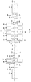
- Embodiments described here, with reference to the drawings, concern an apparatus 10 to make a metal mesh 11.
- the metal mesh 11 is defined by longitudinal rods 13 and 15 and transverse rods 14.
- the rods 13, 14, 15 can have a diameter D and a reciprocal pitch P which can be fixed or different, said characteristics being defined according to the operating needs of the metal mesh 11.
- the rods whether they are longitudinal 13 and 15 or transverse 14, can have a round cross section, or square, rectangular or oval etc.
- the rods 13, 14 and 15 can be provided on their surface with anchoring ribs to obtain a better grip with the concrete.
- the transverse rods 14 are welded with the first and second longitudinal rods 13 and 15, for example electro-welded in correspondence with the zones of reciprocal overlap.
- the apparatus 10 comprises a first operating group 16 and a second operating group 34, disposed in sequence, that is, in series, and functionally coordinated with each other.
- the first operating group 16 provides, on each occasion, a reticular semi-worked product 12 to the second operating group 34 to complete it and form a metal mesh 11.
- the reticular semi-worked product 12 acts as a base frame and is defined by the transverse rods 14 welded to at least two first longitudinal rods 13 located in the desired position.
- the reticular semi-worked product 12 thus obtained is then completed with second longitudinal rods 15 to form a metal mesh 11.
- the second longitudinal rods 15 are disposed substantially parallel to the first longitudinal rods 13, and can be interposed between them.
- transverse rods 14 present in the reticular semi-worked product 12 act as stabilizers of the reticular semi-worked product 12 itself, for the subsequent application of the second longitudinal rods 15.
- the first operating group 16 can comprise a first feed group 17 configured to feed the at least two first longitudinal rods 13 for a predefined length in respective first directions D1, parallel to each other.
- the first feed group 17 is configured to feed the at least two first longitudinal rods 13 on a first lying plane P1.
- the first feed group 17 is also configured to move the first longitudinal rods 13 at a desired and controlled pitch in said first direction D1.
- This step-wise feed which takes place in the first direction D1, also defines the axis of advance of the reticular semi-worked product 12 in formation in the first operating group 16.
- the first operating group 16 also comprises a second feed group 18, configured to feed in a second direction D2, transverse to the first direction D1, on each occasion a transverse rod 14, lying on a second feed plane P2, parallel to the first feed plane P1.
- the first feed plane P1 and the second feed plane P2 can be reciprocally distanced from each other by a distance sufficient to allow to position the first longitudinal rods 13 above the transverse rods 14.
- the second feed group 18 is configured to move one of the transverse rods 14 linearly and on each occasion, in order to position it above or below the first longitudinal rods 13.
- the second feed group 18 moves the transverse rods 14 linearly in a direction parallel to their oblong development.
- the second feed group 18 can operate orthogonally, or at another desired angle, with respect to the first feed unit 17, and is configured to feed individual transverse rods 14 for a predefined length on each occasion and with every feed step of the first longitudinal rods 13.
- the directions D1 and D2 are disposed at 90° with respect to each other.
- the first operating group 16 also comprises a first welding unit 19 configured to weld, on each occasion, the transverse rod 14 fed by the second feed group 18 to the first longitudinal rods 13 and obtain the reticular semi-worked product 12.
- the first welding unit 19 is positioned in, that is, it extends in a direction parallel to the second direction D2 to weld at each step, and at each feed of the individual transverse rod 14, the first longitudinal rods 13 to transverse rods 14 to obtain the reticular semi-worked product 12.
- the second feed group 18 is disposed at one end of the first welding unit 19 and is configured to insert, on each occasion, a transverse rod 14 in the first welding unit 19 in the second direction D2.
- the second operating group 34 comprises a reception and movement unit 35 configured to receive and feed, at a controlled and desired pitch, the reticular semi-worked product 12 along a movement axis M located, during use, substantially parallel to the longitudinal axis of the transverse rods 14.
- the reception and movement unit 35 is configured to receive the reticular semi-worked product 12 from the first welding unit 19 and move it toward the second welding unit 37.
- the reception and movement unit 35 defines a support plane for the reticular semi-worked product 12 which can be located substantially parallel to the first feed plane P1 and to the second feed plane P2. This prevents, during the movement, the reticular semi-worked product 12 from being subjected to unwanted flection or bending which can compromise the quality of the final metal mesh to be obtained.
- the second operating group 34 also comprises a third feed group 36 configured to feed, on each occasion, a second longitudinal rod 15 lying on a third feed plane P3 parallel to the second feed plane P2 and position it, during use, parallel to the first longitudinal rods 13 of the reticular semi-worked product 12.
- the third feed group 36 is configured to move linearly along an axis of feed A, on each occasion, one of the second longitudinal rods 15 to the second welding unit 37.
- the third feed group 36 can linearly move the second longitudinal rods 15 in a direction parallel to their longitudinal development.
- the second longitudinal rod 15 can be provided, with respect to the transverse rods 14, on the same side, or on the same plane, in which the first longitudinal rods 15 are present (as shown in fig. 5 ) or, alternatively, on the opposite side.
- the third feed group 36 is configured to feed, with every movement step of the reticular semi-worked product 12, a single second longitudinal rod 15 for a predefined length.
- the feed takes place along an axis of feed A angled at a desired angle, advantageously but not exclusively 90° or orthogonal with respect to the movement axis M.
- the second operating group 34 also comprises a second welding unit 37 configured to weld, on each occasion, one of the second longitudinal rods 15 to the transverse rods 14 which are already previously welded to the at least two first longitudinal rods 13.
- the second welding unit 37 operates in a coordinated manner with the third feed group 36, and carries out the welding of a second longitudinal rod 15 at each movement step of the reticular semi-worked product 12 to obtain a desired metal mesh 11.
- the second welding unit 37 is positioned along, that is, it extends in a direction parallel to the axis of feed A to weld at each movement step of the reticular semi-worked product 12, and at each feed of the single second longitudinal rod 15, the second longitudinal rod 15 to the transverse rods 14 to obtain the metal mesh 11.
- the third feed group 36 is disposed at one end of the second welding unit 37 and is configured to insert, on each occasion, a second longitudinal rod 15 into the second welding unit 37 along the axis of feed A.
- the first feed group 17 defines an axis of advance of the reticular semi-worked product 12 which is parallel to the first direction D1.
- the axes of advance of the first operating group 16 and of the second operating group 34 are angled with each other, for example comprised between 60° and 120°, in this case by 90°.
- the movement axis M of the second operating group 34 is substantially parallel to the second feed direction D2 of the transverse rods 14.
- the first direction D1 and the movement axis M are positioned respectively like the longitudinal axis of the first longitudinal rods 13 and the longitudinal axis of the transverse rods 14.
- the first and second operating groups 16 and 34 are located sequential and substantially aligned on the same axis of advance.
- the first direction D1 is parallel to the movement axis M.
- a rotation and positioning member 43 is interposed, configured to rotate the reticular semi-worked product 12.
- the rotation and positioning member 43 is configured to rotate the reticular semi-worked product 12 keeping it parallel to the first feed plane P1.
- the rotation and positioning member 43 is configured to rotate the reticular semi-worked product 12 so as to dispose the first longitudinal rods 13 substantially parallel to the second direction D2.
- the first feed group 17 comprises a plurality of feed units 20 to feed the first longitudinal rods 13.
- the second feed group 18 comprises a feed unit 20 to supply the transverse rods 14.
- the third feed group 36 comprises a feed unit 20 which supplies the second longitudinal rods 15.
- the feed units 20 can comprise a feed member 21 configured to feed, on each occasion, a single rod having a desired diameter.
- the feed member 21 can comprise at least one of, or a combination of, a coil 22 to supply metal rods, a straightening member 23 for the rods, a drawing member 25, a guide member 27, a shearing member 28 and measuring means 24 to measure the length of the rod fed.
- At least one of either the longitudinal rods 13 and 15 or the transverse rods 14 can be fed from stores 26 with pre-sized rods, already straightened, to the required size, or supplied in the form of segments with a predetermined length.
- the first feed group 17 can advantageously comprise only two feed units 20, since this number of feed units 20 is the minimum number required to produce a reticular semi-worked product 12.
- This configuration has the advantage of considerably reducing the number of feed units 20 usually used in known solutions.
- the support members 29 define a support and movement plane for the reticular semi-worked product 12 which is formed in the first operating group 16.
- the support and movement plane can be substantially parallel to the first feed plane P1 and to the second feed plane P2.
- the interaxis between the transverse rods 14 is defined on each occasion.
- the welding unit 19 comprises at least two welding members 30 configured to weld on each occasion, for example by electro-welding, the first longitudinal rods 13 to the transverse rods 14.
- the welding device 37 comprises a plurality of welding members 30 to weld on each occasion, for example by electro-welding, the second longitudinal rods 15 to the reticular semi-worked product 12.
- Each welding member 30 can be positioned in correspondence with one of the reciprocal overlapping zones of the respective rods.
- the welding members 30 can be moved by suitable actuators along a positioning guide 31, parallel to the second direction D2, for those of the first welding unit 19, or parallel to the axis of feed A, for those of the second welding unit 37.
- the actuators are configured to position the welding members in the desired positions along the positioning guide 31 on each occasion and according to the desired mesh sizes.
- each welding member 30 can comprise a first electrode 32 and a second electrode 33 opposite each other with respect to the zones of reciprocal overlapping of the first longitudinal rod 13 and the transverse rod 14.
- the first and second electrode 32 and 33 can be electrically powered by an electric power generator, not shown, to apply the energy necessary for welding to the first longitudinal rods 13 and the transverse rods 14.
- At least one of either the first electrode 32 or the second electrode 33 can be selectively movable between a first position, in which the two electrodes 32 and 33 are distanced from each other, defining a gap where the rods to be welded can be put, and a second welding position, in which the two electrodes 32 and 33 clamp and weld the rods.
- the reception and movement unit 35 of the second operating group 34 can comprise a guide device 38 disposed angled, or advantageously orthogonal, to the first direction D1.
- the guide device 38 is disposed substantially parallel, or aligned, to the first direction D1.
- the guide device 38 defines the movement axis M of the second operating group 34.
- the guide device 38 can comprise one or more guide elements 39 aligned in a direction parallel to the movement axis M.
- the reception and movement unit 35 can comprise a movement member 40, such as a slider or other similar member, able to receive the reticular semi-worked product 12 from the first operating group 16 to move it along the movement axis M defined by the guide device 38.
- a movement member 40 such as a slider or other similar member, able to receive the reticular semi-worked product 12 from the first operating group 16 to move it along the movement axis M defined by the guide device 38.
- the movement member 40 can also be configured to rotate so as to orient the reticular semi-worked product 12 in the desired manner and then move it along the movement axis M defined by the guide device 38.
- the reception and movement unit 35 can comprise a control device 41 configured to drive the movement member 40 in a controlled manner and with the pitch desired on each occasion along the movement axis M.
- the controlled movement of the movement member 40 is carried out at desired pitches according to the interaxis to be obtained between the second longitudinal rods 15.
- the apparatus 10 can comprise a control and command unit 42 configured to command at least one of either the first operating group 16 or the second operating group 34, or parts thereof.
- control and command unit 42 can be configured to control and command the feed units 20 and the reception and movement unit 35 in a coordinated manner to make metal meshes 11 having the desired mesh sizes on each occasion.
- control and command unit 42 can comprise, for example, a microcontroller, a programmable electronic circuit, or any similar unit, which allows to manage the functioning of the components of the apparatus 10.
- the present invention also concerns a method to make a metal mesh 11 which provides to:
Landscapes
- Engineering & Computer Science (AREA)
- Mechanical Engineering (AREA)
- Wire Processing (AREA)
- Reinforcement Elements For Buildings (AREA)
- Control And Other Processes For Unpacking Of Materials (AREA)
Priority Applications (1)
| Application Number | Priority Date | Filing Date | Title |
|---|---|---|---|
| PL18700776T PL3573777T3 (pl) | 2017-01-24 | 2018-01-24 | Urządzenie i sposób do wykonania metalowej siatki |
Applications Claiming Priority (2)
| Application Number | Priority Date | Filing Date | Title |
|---|---|---|---|
| IT102017000007565A IT201700007565A1 (it) | 2017-01-24 | 2017-01-24 | Apparato e metodo per realizzare una rete metallica |
| PCT/EP2018/051657 WO2018138117A1 (en) | 2017-01-24 | 2018-01-24 | Apparatus and method to make a metal mesh |
Publications (2)
| Publication Number | Publication Date |
|---|---|
| EP3573777A1 EP3573777A1 (en) | 2019-12-04 |
| EP3573777B1 true EP3573777B1 (en) | 2021-01-20 |
Family
ID=58737779
Family Applications (1)
| Application Number | Title | Priority Date | Filing Date |
|---|---|---|---|
| EP18700776.0A Active EP3573777B1 (en) | 2017-01-24 | 2018-01-24 | Apparatus and method to make a metal mesh |
Country Status (16)
| Country | Link |
|---|---|
| US (1) | US11440082B2 (da) |
| EP (1) | EP3573777B1 (da) |
| JP (1) | JP7079785B2 (da) |
| KR (1) | KR102502037B1 (da) |
| CN (1) | CN110461494B (da) |
| AR (1) | AR110843A1 (da) |
| AU (1) | AU2018213897B2 (da) |
| DK (1) | DK3573777T3 (da) |
| ES (1) | ES2858338T3 (da) |
| HU (1) | HUE054323T2 (da) |
| IT (1) | IT201700007565A1 (da) |
| PL (1) | PL3573777T3 (da) |
| PT (1) | PT3573777T (da) |
| RU (1) | RU2753816C2 (da) |
| TW (1) | TWI746778B (da) |
| WO (1) | WO2018138117A1 (da) |
Families Citing this family (2)
| Publication number | Priority date | Publication date | Assignee | Title |
|---|---|---|---|---|
| CN110125290B (zh) * | 2019-06-05 | 2020-11-24 | 安徽马钢比亚西钢筋焊网有限公司 | 一种中空型焊网的自动成型方法 |
| GB2611760B (en) * | 2021-10-12 | 2024-03-27 | Laing Orourke Plc | Method for making rebar arrays |
Family Cites Families (24)
| Publication number | Priority date | Publication date | Assignee | Title |
|---|---|---|---|---|
| US1937078A (en) * | 1932-01-23 | 1933-11-28 | Wickwire Brothers | Wire fabric machine |
| US2712837A (en) * | 1950-02-11 | 1955-07-12 | Northwestern Steel & Wire Co | Welded wire mesh fabricating machine |
| SU596344A1 (ru) * | 1976-04-05 | 1978-03-05 | Ростовский-на-Дону научно-исследовательский институт технологии машиностроения | Машина дл контактной точечной сварки сеток |
| EP0162183B1 (fr) * | 1984-04-24 | 1988-12-07 | SISMO INTERNATIONAL personenvennootschap met beperkte aansprakelijkheid | Procédé d'assemblage de structures métalliques tridimensionelles, et machine pour leur réalisation |
| SU1409435A1 (ru) * | 1986-06-16 | 1988-07-15 | Завод Железобетонных Изделий N5 Треста "Стройдеталь" Главкиевгорстроя | Устройство дл изготовлени пространственных арматурных каркасов |
| IN171977B (da) * | 1988-06-29 | 1993-02-27 | Du Pont | |
| JP2500811B2 (ja) * | 1990-12-04 | 1996-05-29 | 鹿島建設株式会社 | 自動鉄筋組立装置 |
| JP3179551B2 (ja) * | 1992-02-12 | 2001-06-25 | 株式会社ツバキ・ナカシマ | 鉄筋網状体製造システム |
| JP3030494B2 (ja) * | 1995-08-11 | 2000-04-10 | 有限会社テクノサービス | クリンプ金網構造物及びそれを使用した型枠装置 |
| JPH09300079A (ja) * | 1996-05-13 | 1997-11-25 | Sanyo Denki Kk | 溶接配筋材の処理方法およびその装置 |
| US6820387B2 (en) * | 2001-08-13 | 2004-11-23 | Abraham Sacks | Self-stiffened welded wire lath assembly |
| ITUD20020135A1 (it) * | 2002-06-18 | 2003-12-18 | Beta Systems Srl | Macchina per la formazione di rete metallica e relativo procedimento |
| WO2005065863A1 (fr) | 2003-12-10 | 2005-07-21 | Issa, Issam | Machine de fabrication en continu de treillis metallique soude |
| AT502466B1 (de) * | 2004-07-20 | 2008-02-15 | Evg Entwicklung Verwert Ges | Verfahren und schweissmaschine zum herstellen von gitterprodukten |
| KR20100020857A (ko) * | 2008-08-13 | 2010-02-23 | 곽선경 | 용접철망의 제조방법 및 그 제조장치 |
| GR1007035B (el) * | 2009-07-22 | 2010-10-27 | Αντωνιος Παναγιωτη Αναγνωστοπουλος | Μεθοδος και συστημα τροφοδοσιας ηλεκτροσυγκολλητικων μηχανων παραγωγης πλεγματος με διαμηκη συρματα |
| RU96510U1 (ru) * | 2010-04-13 | 2010-08-10 | Александр Федорович Шашин | Устройство для сварки арматурных сеток преимущественно с укороченными поперечными стержнями, смещенными к ее боковым сторонам |
| TWM394197U (en) * | 2010-08-10 | 2010-12-11 | Ruentex Eng & Constr Co Ltd | Wire net forming device |
| TWM497187U (zh) * | 2013-04-18 | 2015-03-11 | Cochrane Gulf Fze | 圍籬板 |
| AT515477B1 (de) * | 2014-02-28 | 2016-03-15 | Christian Patterer | Verfahren zur Herstellung von Doppelstabmatten und Gittermatten in Aluminium |
| GR1008523B (el) * | 2014-04-01 | 2015-07-09 | Αντωνιος Παναγιωτη Αναγνωστοπουλος | Μεθοδος και συστημα τροφοδοσιας διαμηκων συρματων ή μπετοβεργων σε μηχανηματα παραγωγης πλεγματος |
| KR101666355B1 (ko) * | 2015-05-05 | 2016-11-18 | 케이원스틸주식회사 | 수로관에 내장되는 용접철망의 철선 용접 및 성형장치 |
| CN105171263B (zh) * | 2015-10-29 | 2017-10-03 | 佛山市华德涞机器人智能科技有限公司 | 一种自动排网焊接设备 |
| US10610919B2 (en) * | 2016-07-07 | 2020-04-07 | Antonios Anagnostopoulos | High-speed mesh producing machines and processes with mesh distortion negation and occupied space reduction |
-
2017
- 2017-01-24 IT IT102017000007565A patent/IT201700007565A1/it unknown
-
2018
- 2018-01-24 TW TW107102555A patent/TWI746778B/zh active
- 2018-01-24 ES ES18700776T patent/ES2858338T3/es active Active
- 2018-01-24 WO PCT/EP2018/051657 patent/WO2018138117A1/en not_active Ceased
- 2018-01-24 RU RU2019125876A patent/RU2753816C2/ru active
- 2018-01-24 HU HUE18700776A patent/HUE054323T2/hu unknown
- 2018-01-24 CN CN201880020520.5A patent/CN110461494B/zh active Active
- 2018-01-24 KR KR1020197024658A patent/KR102502037B1/ko active Active
- 2018-01-24 DK DK18700776.0T patent/DK3573777T3/da active
- 2018-01-24 PT PT187007760T patent/PT3573777T/pt unknown
- 2018-01-24 AU AU2018213897A patent/AU2018213897B2/en active Active
- 2018-01-24 US US16/479,727 patent/US11440082B2/en active Active
- 2018-01-24 EP EP18700776.0A patent/EP3573777B1/en active Active
- 2018-01-24 AR ARP180100152A patent/AR110843A1/es active IP Right Grant
- 2018-01-24 PL PL18700776T patent/PL3573777T3/pl unknown
- 2018-01-24 JP JP2019539973A patent/JP7079785B2/ja active Active
Non-Patent Citations (1)
| Title |
|---|
| None * |
Also Published As
| Publication number | Publication date |
|---|---|
| US20210114081A1 (en) | 2021-04-22 |
| ES2858338T3 (es) | 2021-09-30 |
| DK3573777T3 (da) | 2021-03-22 |
| JP2020506805A (ja) | 2020-03-05 |
| CN110461494B (zh) | 2021-08-27 |
| KR20190126304A (ko) | 2019-11-11 |
| JP7079785B2 (ja) | 2022-06-02 |
| KR102502037B1 (ko) | 2023-02-21 |
| US11440082B2 (en) | 2022-09-13 |
| RU2019125876A3 (da) | 2021-07-08 |
| AU2018213897B2 (en) | 2023-06-01 |
| BR112019015249A2 (pt) | 2020-04-14 |
| RU2019125876A (ru) | 2021-02-26 |
| HUE054323T2 (hu) | 2021-08-30 |
| TWI746778B (zh) | 2021-11-21 |
| TW201827140A (zh) | 2018-08-01 |
| AR110843A1 (es) | 2019-05-08 |
| PL3573777T3 (pl) | 2021-06-28 |
| EP3573777A1 (en) | 2019-12-04 |
| PT3573777T (pt) | 2021-03-22 |
| AU2018213897A1 (en) | 2019-08-22 |
| CN110461494A (zh) | 2019-11-15 |
| IT201700007565A1 (it) | 2018-07-24 |
| RU2753816C2 (ru) | 2021-08-23 |
| WO2018138117A1 (en) | 2018-08-02 |
Similar Documents
| Publication | Publication Date | Title |
|---|---|---|
| EP3634661B9 (en) | Apparatus and method to make a wire mesh | |
| CN107225315B (zh) | 一种弧形网片焊网机 | |
| EP3573777B1 (en) | Apparatus and method to make a metal mesh | |
| EP2600991B1 (en) | Method and apparatus for correcting twist stresses in metal rods | |
| KR102189749B1 (ko) | 금속 와이어를 드로잉 및 교정하는 장치, 및 해당 드로잉 및 교정 방법 | |
| WO2013000551A1 (de) | Verfahren und einrichtung zur kontinuierlichen herstellung eines gitterträgs | |
| EP2433724A1 (en) | Feeding system and relevant transversal feeder for entire bars or steel bars suitable for automatic plants producing electric welding wire netting with particular shapes | |
| EP1982779A1 (en) | Apparatus and method for manufacturing beam-reinforcement latticework-like wire structure on a just-in-time basis | |
| US12337374B2 (en) | Machine and method for producing simply reinforced steel wire meshes | |
| EP2529857B1 (de) | Verfahren und Einrichtung zur Herstellung von bogenförmigen Baustahlmatten | |
| EP0674553B1 (en) | Automatic bar feeding device | |
| EA005848B1 (ru) | Способ изготовления решетчатых конструкций и устройство для его реализации | |
| EP2435199A2 (en) | Automated apparatus for the differential advancement of metal rods and/or bars for the construction of rectilinear and/or curvilinear electro-welded elements, and associated production method | |
| BG5316U1 (bg) | Технологична линия за производство на телени мрежи | |
| BR112019015249B1 (pt) | Aparelho e método para fazer uma malha de metal | |
| RU2271915C2 (ru) | Устройство для изготовления решетчатых конструкций | |
| KR101914865B1 (ko) | 건설자재용 부품 제조 장치 | |
| BG5036U1 (bg) | Линия за производство на арматурни заготовки | |
| BG5044U1 (bg) | Автоматизирана линия за производство на арматурни заготовки | |
| DE202013005630U1 (de) | Mehrstufige Biegevorrichtung zur Herstellung von Drahtspiralen |
Legal Events
| Date | Code | Title | Description |
|---|---|---|---|
| STAA | Information on the status of an ep patent application or granted ep patent |
Free format text: STATUS: UNKNOWN |
|
| STAA | Information on the status of an ep patent application or granted ep patent |
Free format text: STATUS: THE INTERNATIONAL PUBLICATION HAS BEEN MADE |
|
| PUAI | Public reference made under article 153(3) epc to a published international application that has entered the european phase |
Free format text: ORIGINAL CODE: 0009012 |
|
| STAA | Information on the status of an ep patent application or granted ep patent |
Free format text: STATUS: REQUEST FOR EXAMINATION WAS MADE |
|
| 17P | Request for examination filed |
Effective date: 20190730 |
|
| AK | Designated contracting states |
Kind code of ref document: A1 Designated state(s): AL AT BE BG CH CY CZ DE DK EE ES FI FR GB GR HR HU IE IS IT LI LT LU LV MC MK MT NL NO PL PT RO RS SE SI SK SM TR |
|
| AX | Request for extension of the european patent |
Extension state: BA ME |
|
| DAV | Request for validation of the european patent (deleted) | ||
| DAX | Request for extension of the european patent (deleted) | ||
| GRAP | Despatch of communication of intention to grant a patent |
Free format text: ORIGINAL CODE: EPIDOSNIGR1 |
|
| STAA | Information on the status of an ep patent application or granted ep patent |
Free format text: STATUS: GRANT OF PATENT IS INTENDED |
|
| INTG | Intention to grant announced |
Effective date: 20200828 |
|
| GRAS | Grant fee paid |
Free format text: ORIGINAL CODE: EPIDOSNIGR3 |
|
| GRAA | (expected) grant |
Free format text: ORIGINAL CODE: 0009210 |
|
| STAA | Information on the status of an ep patent application or granted ep patent |
Free format text: STATUS: THE PATENT HAS BEEN GRANTED |
|
| AK | Designated contracting states |
Kind code of ref document: B1 Designated state(s): AL AT BE BG CH CY CZ DE DK EE ES FI FR GB GR HR HU IE IS IT LI LT LU LV MC MK MT NL NO PL PT RO RS SE SI SK SM TR |
|
| REG | Reference to a national code |
Ref country code: GB Ref legal event code: FG4D |
|
| REG | Reference to a national code |
Ref country code: CH Ref legal event code: EP |
|
| REG | Reference to a national code |
Ref country code: DE Ref legal event code: R096 Ref document number: 602018012046 Country of ref document: DE |
|
| REG | Reference to a national code |
Ref country code: AT Ref legal event code: REF Ref document number: 1355929 Country of ref document: AT Kind code of ref document: T Effective date: 20210215 |
|
| REG | Reference to a national code |
Ref country code: IE Ref legal event code: FG4D |
|
| REG | Reference to a national code |
Ref country code: CH Ref legal event code: NV Representative=s name: IPRIME RENTSCH KAELIN AG, CH |
|
| REG | Reference to a national code |
Ref country code: DK Ref legal event code: T3 Effective date: 20210318 Ref country code: PT Ref legal event code: SC4A Ref document number: 3573777 Country of ref document: PT Date of ref document: 20210322 Kind code of ref document: T Free format text: AVAILABILITY OF NATIONAL TRANSLATION Effective date: 20210315 |
|
| REG | Reference to a national code |
Ref country code: FI Ref legal event code: FGE Ref country code: RO Ref legal event code: EPE |
|
| REG | Reference to a national code |
Ref country code: NL Ref legal event code: FP |
|
| REG | Reference to a national code |
Ref country code: SE Ref legal event code: TRGR |
|
| REG | Reference to a national code |
Ref country code: GR Ref legal event code: EP Ref document number: 20210400621 Country of ref document: GR Effective date: 20210416 |
|
| REG | Reference to a national code |
Ref country code: SK Ref legal event code: T3 Ref document number: E 36911 Country of ref document: SK |
|
| REG | Reference to a national code |
Ref country code: NO Ref legal event code: T2 Effective date: 20210120 |
|
| REG | Reference to a national code |
Ref country code: LT Ref legal event code: MG9D |
|
| PG25 | Lapsed in a contracting state [announced via postgrant information from national office to epo] |
Ref country code: BG Free format text: LAPSE BECAUSE OF FAILURE TO SUBMIT A TRANSLATION OF THE DESCRIPTION OR TO PAY THE FEE WITHIN THE PRESCRIBED TIME-LIMIT Effective date: 20210420 Ref country code: HR Free format text: LAPSE BECAUSE OF FAILURE TO SUBMIT A TRANSLATION OF THE DESCRIPTION OR TO PAY THE FEE WITHIN THE PRESCRIBED TIME-LIMIT Effective date: 20210120 Ref country code: LT Free format text: LAPSE BECAUSE OF FAILURE TO SUBMIT A TRANSLATION OF THE DESCRIPTION OR TO PAY THE FEE WITHIN THE PRESCRIBED TIME-LIMIT Effective date: 20210120 |
|
| REG | Reference to a national code |
Ref country code: SK Ref legal event code: T4 Ref document number: E 36911 Country of ref document: SK |
|
| REG | Reference to a national code |
Ref country code: HU Ref legal event code: AG4A Ref document number: E054323 Country of ref document: HU |
|
| PG25 | Lapsed in a contracting state [announced via postgrant information from national office to epo] |
Ref country code: LV Free format text: LAPSE BECAUSE OF FAILURE TO SUBMIT A TRANSLATION OF THE DESCRIPTION OR TO PAY THE FEE WITHIN THE PRESCRIBED TIME-LIMIT Effective date: 20210120 Ref country code: RS Free format text: LAPSE BECAUSE OF FAILURE TO SUBMIT A TRANSLATION OF THE DESCRIPTION OR TO PAY THE FEE WITHIN THE PRESCRIBED TIME-LIMIT Effective date: 20210120 |
|
| PG25 | Lapsed in a contracting state [announced via postgrant information from national office to epo] |
Ref country code: IS Free format text: LAPSE BECAUSE OF FAILURE TO SUBMIT A TRANSLATION OF THE DESCRIPTION OR TO PAY THE FEE WITHIN THE PRESCRIBED TIME-LIMIT Effective date: 20210520 Ref country code: LU Free format text: LAPSE BECAUSE OF NON-PAYMENT OF DUE FEES Effective date: 20210124 |
|
| REG | Reference to a national code |
Ref country code: ES Ref legal event code: FG2A Ref document number: 2858338 Country of ref document: ES Kind code of ref document: T3 Effective date: 20210930 |
|
| REG | Reference to a national code |
Ref country code: DE Ref legal event code: R097 Ref document number: 602018012046 Country of ref document: DE |
|
| PG25 | Lapsed in a contracting state [announced via postgrant information from national office to epo] |
Ref country code: EE Free format text: LAPSE BECAUSE OF FAILURE TO SUBMIT A TRANSLATION OF THE DESCRIPTION OR TO PAY THE FEE WITHIN THE PRESCRIBED TIME-LIMIT Effective date: 20210120 Ref country code: MC Free format text: LAPSE BECAUSE OF FAILURE TO SUBMIT A TRANSLATION OF THE DESCRIPTION OR TO PAY THE FEE WITHIN THE PRESCRIBED TIME-LIMIT Effective date: 20210120 Ref country code: SM Free format text: LAPSE BECAUSE OF FAILURE TO SUBMIT A TRANSLATION OF THE DESCRIPTION OR TO PAY THE FEE WITHIN THE PRESCRIBED TIME-LIMIT Effective date: 20210120 |
|
| PLBE | No opposition filed within time limit |
Free format text: ORIGINAL CODE: 0009261 |
|
| STAA | Information on the status of an ep patent application or granted ep patent |
Free format text: STATUS: NO OPPOSITION FILED WITHIN TIME LIMIT |
|
| 26N | No opposition filed |
Effective date: 20211021 |
|
| PG25 | Lapsed in a contracting state [announced via postgrant information from national office to epo] |
Ref country code: AL Free format text: LAPSE BECAUSE OF FAILURE TO SUBMIT A TRANSLATION OF THE DESCRIPTION OR TO PAY THE FEE WITHIN THE PRESCRIBED TIME-LIMIT Effective date: 20210120 |
|
| PG25 | Lapsed in a contracting state [announced via postgrant information from national office to epo] |
Ref country code: SI Free format text: LAPSE BECAUSE OF FAILURE TO SUBMIT A TRANSLATION OF THE DESCRIPTION OR TO PAY THE FEE WITHIN THE PRESCRIBED TIME-LIMIT Effective date: 20210120 |
|
| REG | Reference to a national code |
Ref country code: AT Ref legal event code: UEP Ref document number: 1355929 Country of ref document: AT Kind code of ref document: T Effective date: 20210120 |
|
| P01 | Opt-out of the competence of the unified patent court (upc) registered |
Effective date: 20230520 |
|
| PG25 | Lapsed in a contracting state [announced via postgrant information from national office to epo] |
Ref country code: CY Free format text: LAPSE BECAUSE OF FAILURE TO SUBMIT A TRANSLATION OF THE DESCRIPTION OR TO PAY THE FEE WITHIN THE PRESCRIBED TIME-LIMIT Effective date: 20210120 |
|
| PG25 | Lapsed in a contracting state [announced via postgrant information from national office to epo] |
Ref country code: MK Free format text: LAPSE BECAUSE OF FAILURE TO SUBMIT A TRANSLATION OF THE DESCRIPTION OR TO PAY THE FEE WITHIN THE PRESCRIBED TIME-LIMIT Effective date: 20210120 |
|
| PG25 | Lapsed in a contracting state [announced via postgrant information from national office to epo] |
Ref country code: MT Free format text: LAPSE BECAUSE OF FAILURE TO SUBMIT A TRANSLATION OF THE DESCRIPTION OR TO PAY THE FEE WITHIN THE PRESCRIBED TIME-LIMIT Effective date: 20210120 |
|
| PGFP | Annual fee paid to national office [announced via postgrant information from national office to epo] |
Ref country code: HU Payment date: 20250205 Year of fee payment: 8 |
|
| PGFP | Annual fee paid to national office [announced via postgrant information from national office to epo] |
Ref country code: DK Payment date: 20250113 Year of fee payment: 8 Ref country code: FI Payment date: 20250128 Year of fee payment: 8 |
|
| PGFP | Annual fee paid to national office [announced via postgrant information from national office to epo] |
Ref country code: NO Payment date: 20250128 Year of fee payment: 8 |
|
| PGFP | Annual fee paid to national office [announced via postgrant information from national office to epo] |
Ref country code: GR Payment date: 20250130 Year of fee payment: 8 |
|
| PGFP | Annual fee paid to national office [announced via postgrant information from national office to epo] |
Ref country code: SK Payment date: 20250114 Year of fee payment: 8 |
|
| PGFP | Annual fee paid to national office [announced via postgrant information from national office to epo] |
Ref country code: TR Payment date: 20250114 Year of fee payment: 8 |
|
| REG | Reference to a national code |
Ref country code: CH Ref legal event code: U11 Free format text: ST27 STATUS EVENT CODE: U-0-0-U10-U11 (AS PROVIDED BY THE NATIONAL OFFICE) Effective date: 20260201 |
|
| PGFP | Annual fee paid to national office [announced via postgrant information from national office to epo] |
Ref country code: NL Payment date: 20260122 Year of fee payment: 9 |
|
| PGFP | Annual fee paid to national office [announced via postgrant information from national office to epo] |
Ref country code: SE Payment date: 20260126 Year of fee payment: 9 |
|
| PGFP | Annual fee paid to national office [announced via postgrant information from national office to epo] |
Ref country code: GB Payment date: 20260126 Year of fee payment: 9 |
|
| PGFP | Annual fee paid to national office [announced via postgrant information from national office to epo] |
Ref country code: ES Payment date: 20260210 Year of fee payment: 9 |
|
| PGFP | Annual fee paid to national office [announced via postgrant information from national office to epo] |
Ref country code: DE Payment date: 20260127 Year of fee payment: 9 Ref country code: IE Payment date: 20260120 Year of fee payment: 9 |
|
| PGFP | Annual fee paid to national office [announced via postgrant information from national office to epo] |
Ref country code: AT Payment date: 20260119 Year of fee payment: 9 |
|
| PGFP | Annual fee paid to national office [announced via postgrant information from national office to epo] |
Ref country code: RO Payment date: 20260121 Year of fee payment: 9 Ref country code: BE Payment date: 20260123 Year of fee payment: 9 Ref country code: IT Payment date: 20260121 Year of fee payment: 9 |
|
| PGFP | Annual fee paid to national office [announced via postgrant information from national office to epo] |
Ref country code: FR Payment date: 20260126 Year of fee payment: 9 |
|
| PGFP | Annual fee paid to national office [announced via postgrant information from national office to epo] |
Ref country code: CH Payment date: 20260201 Year of fee payment: 9 Ref country code: PT Payment date: 20260116 Year of fee payment: 9 Ref country code: CZ Payment date: 20260121 Year of fee payment: 9 |
|
| PGFP | Annual fee paid to national office [announced via postgrant information from national office to epo] |
Ref country code: PL Payment date: 20260120 Year of fee payment: 9 |