EP3574323B1 - Dispositif à flux latéral - Google Patents
Dispositif à flux latéral Download PDFInfo
- Publication number
- EP3574323B1 EP3574323B1 EP18744679.4A EP18744679A EP3574323B1 EP 3574323 B1 EP3574323 B1 EP 3574323B1 EP 18744679 A EP18744679 A EP 18744679A EP 3574323 B1 EP3574323 B1 EP 3574323B1
- Authority
- EP
- European Patent Office
- Prior art keywords
- wicking pad
- reservoirs
- substrate
- lateral flow
- reservoir
- Prior art date
- Legal status (The legal status is an assumption and is not a legal conclusion. Google has not performed a legal analysis and makes no representation as to the accuracy of the status listed.)
- Active
Links
Images

Classifications
-
- G—PHYSICS
- G01—MEASURING; TESTING
- G01N—INVESTIGATING OR ANALYSING MATERIALS BY DETERMINING THEIR CHEMICAL OR PHYSICAL PROPERTIES
- G01N33/00—Investigating or analysing materials by specific methods not covered by groups G01N1/00 - G01N31/00
- G01N33/48—Biological material, e.g. blood, urine; Haemocytometers
- G01N33/50—Chemical analysis of biological material, e.g. blood, urine; Testing involving biospecific ligand binding methods; Immunological testing
- G01N33/53—Immunoassay; Biospecific binding assay; Materials therefor
- G01N33/543—Immunoassay; Biospecific binding assay; Materials therefor with an insoluble carrier for immobilising immunochemicals
- G01N33/54366—Apparatus specially adapted for solid-phase testing
- G01N33/54386—Analytical elements
- G01N33/54387—Immunochromatographic test strips
- G01N33/54388—Immunochromatographic test strips based on lateral flow
-
- B—PERFORMING OPERATIONS; TRANSPORTING
- B01—PHYSICAL OR CHEMICAL PROCESSES OR APPARATUS IN GENERAL
- B01L—CHEMICAL OR PHYSICAL LABORATORY APPARATUS FOR GENERAL USE
- B01L2200/00—Solutions for specific problems relating to chemical or physical laboratory apparatus
- B01L2200/06—Fluid handling related problems
- B01L2200/0689—Sealing
-
- B—PERFORMING OPERATIONS; TRANSPORTING
- B01—PHYSICAL OR CHEMICAL PROCESSES OR APPARATUS IN GENERAL
- B01L—CHEMICAL OR PHYSICAL LABORATORY APPARATUS FOR GENERAL USE
- B01L2300/00—Additional constructional details
- B01L2300/06—Auxiliary integrated devices, integrated components
- B01L2300/069—Absorbents; Gels to retain a fluid
-
- B—PERFORMING OPERATIONS; TRANSPORTING
- B01—PHYSICAL OR CHEMICAL PROCESSES OR APPARATUS IN GENERAL
- B01L—CHEMICAL OR PHYSICAL LABORATORY APPARATUS FOR GENERAL USE
- B01L2300/00—Additional constructional details
- B01L2300/16—Surface properties and coatings
- B01L2300/161—Control and use of surface tension forces, e.g. hydrophobic, hydrophilic
- B01L2300/165—Specific details about hydrophobic, oleophobic surfaces
-
- B—PERFORMING OPERATIONS; TRANSPORTING
- B01—PHYSICAL OR CHEMICAL PROCESSES OR APPARATUS IN GENERAL
- B01L—CHEMICAL OR PHYSICAL LABORATORY APPARATUS FOR GENERAL USE
- B01L2400/00—Moving or stopping fluids
- B01L2400/04—Moving fluids with specific forces or mechanical means
- B01L2400/0403—Moving fluids with specific forces or mechanical means specific forces
- B01L2400/0406—Moving fluids with specific forces or mechanical means specific forces capillary forces
-
- B—PERFORMING OPERATIONS; TRANSPORTING
- B01—PHYSICAL OR CHEMICAL PROCESSES OR APPARATUS IN GENERAL
- B01L—CHEMICAL OR PHYSICAL LABORATORY APPARATUS FOR GENERAL USE
- B01L2400/00—Moving or stopping fluids
- B01L2400/04—Moving fluids with specific forces or mechanical means
- B01L2400/0475—Moving fluids with specific forces or mechanical means specific mechanical means and fluid pressure
-
- B—PERFORMING OPERATIONS; TRANSPORTING
- B01—PHYSICAL OR CHEMICAL PROCESSES OR APPARATUS IN GENERAL
- B01L—CHEMICAL OR PHYSICAL LABORATORY APPARATUS FOR GENERAL USE
- B01L3/00—Containers or dishes for laboratory use, e.g. laboratory glassware; Droppers
- B01L3/50—Containers for the purpose of retaining a material to be analysed, e.g. test tubes
- B01L3/502—Containers for the purpose of retaining a material to be analysed, e.g. test tubes with fluid transport, e.g. in multi-compartment structures
- B01L3/5023—Containers for the purpose of retaining a material to be analysed, e.g. test tubes with fluid transport, e.g. in multi-compartment structures with a sample being transported to, and subsequently stored in an absorbent for analysis
Definitions
- blotting e.g., Southern, northern, western, far western, eastern, vacuum, middle eastern, eastern-western, and far-eastern blotting, etc.
- blotting techniques involve immobilization of the analyte(s) to be detected and contacting the analyte(s) with a binding agent (e.g., an antibody).
- binding agent e.g., an antibody
- US 2013/0164193 A1 relates to the field of biology and detection of analytes from environmental and biological fluids and it discloses a lateral flow capillary device and uses thereof comprising a unipath capillary flow matrix and a plurality of reservoirs each in fluid communication with the capillary flow matrix.
- WO 2010/007613 A1 relates to devices and methods for performing accelerated analytic and synthetic analyses procedures and it discloses a capturing device including a lateral capillary flow matrix and a capturing matrix in fluid communication with the lateral capillary flow matrix such as to produce a lateral capillary flow in the capturing matrix having a lower velocity than that in the lateral capillary flow matrix.
- lateral flow assay devices Provided herein are lateral flow assay devices and methods of using such devices.
- a lateral flow device comprising a wicking pad composed of a porous material, the wicking pad having a planar region for contacting a substrate (e.g., a Western blot) comprising immobilized analytes (e.g., proteins); and wherein the wicking pad has a first end, a second end and two lateral edges; a support layer bonded to a first planar surface of the wicking pad; a top layer bonded to a second planar surface of the wicking pad so that the wicking pad is sandwiched between the support layer and the top layer, the top layer comprising two or more reservoirs spatially separated from each other, wherein the longitudinal axis of each reservoir is perpendicular to the lateral edges of the wicking pad, wherein each of the reservoirs is in fluid communication with the first end of the wicking pad, and wherein each of the reservoirs comprises an aperture through which a solution is released from the reservoir; and a pump
- the wicking pad further comprises two or more zones separated from each other by a hydrophobic or impermeable barrier that is parallel to the lateral edges of the wicking pad.
- the edges of the wicking pad are sealed with a water-tight material or with a heat seal.
- the water-tight material is selected from acrylic, wax, and photopolymers.
- the top layer further comprises a first opening through which the substrate is contacted to the planar region of the wicking pad downstream from the reservoirs. In some embodiments, the top layer further comprises a second opening through which the pump is contacted to the second planar surface of the wicking pad downstream from the first opening. In some embodiments, the top layer comprises an opening through which the substrate is contacted to the planar region and through which the pump is contacted to the wicking pad downstream from the planar region.
- the aperture is a slot.
- the reservoirs comprise two or more sets of reservoirs spatially separated from and adjacent to each other on the width axis of the lateral flow device. In some embodiments, each of the reservoirs spans a width of the wicking pad. In some embodiments, at least a first reservoir shares a wall with at least a second reservoir.
- the support layer and the top layer are formed from a liquid impermeable material.
- the liquid impermeable material is selected from polypropylene, polycarbonate, polystyrene, polyethylene terephthalate, and polyethylene terephthalate glycol-modified
- the analytes are proteins.
- a method of performing lateral flow assays comprises providing a lateral flow device as described in the first aspect above or elsewhere herein; optionally applying a lateral flow buffer, i.e. a running buffer to the wicking pad; applying a substrate comprising proteins (e.g., a Western blot) to the planar region for contacting the substrate; applying a different reagent solution to each of the reservoirs starting with a reservoir closest to the planar region for applying the substrate; and allowing lateral flow of the reagent solutions from the reservoirs to the pump such that each of the reagents in the reagent solutions is sequentially transported in the wicking pad and is contacted to the proteins on the substrate.
- a lateral flow buffer i.e. a running buffer to the wicking pad
- a substrate comprising proteins (e.g., a Western blot)
- the different reagent solutions are applied to the reservoirs sequentially or simultaneously.
- the allowing lateral flow step comprises allowing primary antibodies from a first reagent solution in a first reservoir to bind to target proteins, if present, on the substrate, followed by allowing a first wash solution from a second reagent solution in a second reservoir to remove unbound primary antibodies from the substrate.
- the allowing lateral flow step further comprises allowing secondary antibodies or a secondary detection reagent from a third reagent solution in a third reservoir to contact the primary antibodies bound to target proteins, if present, on the substrate.
- the allowing lateral flow step further comprises allowing a second wash solution from a fourth reagent solution in a fourth reservoir to remove unbound secondary antibodies from the substrate.
- the volume of the second wash solution is at least twice the volume of the third reagent solution having the secondary antibody.
- the method further comprises following binding of the primary antibodies to the target proteins if present, optionally following contact of secondary antibodies or secondary detection reagents to the primary antibodies, optionally removing the substrate, and detecting the binding of the primary antibodies to the target proteins if present.
- the methods further comprise applying a substantially uniform pressure to the pump.
- lateral flow devices and methods of using such devices that allow for efficient lateral flow detection of analytes (e.g., proteins, nucleic acids) immobilized on substrates (e.g., western blot membranes) or the wicking pad (e.g., a diagnostic application) using specific binding agents (e.g., antibodies).
- analytes e.g., proteins, nucleic acids
- substrates e.g., western blot membranes
- specific binding agents e.g., antibodies
- Lateral flow devices and methods of using such devices have been discovered that deliver different solutions (e.g., samples having one or more analytes, specific binding agents, running buffer, wash solutions) sequentially and hands-free to a wicking pad in intimate contact with a substrate having analytes or binding agents immobilized thereon.
- the solutions are delivered sequentially to the wicking pad from at least two reservoirs bonded to the wicking pad of the lateral flow devices.
- the devices described herein can be configured in a single-use device, allowing for an affordable and simple assay format.
- analyte refers to a biological molecule, e.g., a protein, nucleic acid, polysaccharide, lipid, antigen, growth factor, hapten, or a portion thereof. Analytes can be reversibly or irreversibly immobilized on a surface, such as a membrane or a wicking pad and detected as described herein.
- immobilized or “embedded” interchangeably refers to reversibly or irreversibly immobilized molecules (e.g., analytes or binding agents).
- reversibly immobilized molecules are immobilized in a manner that allows the molecules, or a portion thereof (e.g., at least 25%, 50%, 60%, 75%, 80% or more of the molecules), to be removed from their immobilized location without substantial denaturation or aggregation.
- a molecule can be reversibly immobilized in or on an absorbent material (e.g., an absorbent pad) by contacting a solution containing the molecule with the absorbent material, thereby soaking up the solution and reversibly immobilizing the molecule.
- an absorbent material e.g., an absorbent pad
- the reversibly immobilized molecule can then be removed by wicking the solution from the absorbent material, or from one region of the absorbent material to another.
- a molecule can be reversibly immobilized on an absorbent material by contacting a solution containing the molecule with the absorbent material, thereby soaking up the solution, and then drying the solution-containing absorbent material.
- the reversibly immobilized molecule can then be removed by contacting the absorbent material with another solution of the same or a different composition, thereby solubilizing the reversibly immobilized molecule, and then wicking the solution from the absorbent material, or from one region of the absorbent material to another.
- Irreversibly immobilized molecules e.g., binding agents or analytes
- binding agents or analytes are immobilized such that they are not removed, or not substantially removed, from their location under mild conditions (e.g., pH between about 4-9, temperature of between about 4-65 °C).
- exemplary irreversibly immobilized molecules include protein analytes or binding agents bound to a nitrocellulose, polyvinylidene fluoride, nylon or polysulfone membrane by standard blotting techniques (e.g., electroblotting).
- exemplary irreversibly immobilized molecules include protein analytes or binding agents bound to glass, plastic (e.g., a microarray, a microfluidic chip, a glass histology slide or a plastic microtiter plate having wells with bound protein analytes therein), particles, nanoparticles or magnetic particles.
- plastic e.g., a microarray, a microfluidic chip, a glass histology slide or a plastic microtiter plate having wells with bound protein analytes therein
- particles e.g., a microarray, a microfluidic chip, a glass histology slide or a plastic microtiter plate having wells with bound protein analytes therein
- binding agent refers to an agent that specifically binds to a molecule such as an analyte. While antibodies are described in many contexts herein, it will be understood that other binding agents can be used instead of antibodies as preferred by the user. A wide variety of binding agents are known in the art, including antibodies, aptamers, affimers, lipocalins (e.g., anticalins), thioredoxin A, bilin binding protein, or proteins containing an ankyrin repeat, the Z domain of staphylococcal protein A, or a fibronectin type III domain. Other binding agents include biotin/streptavidin, chelating agents, chromatography resins, affinity tags, or functionalized beads, nanoparticles and magnetic particles.
- binding agent such as an antibody or antibody fragment
- binds to a target with at least 2-fold greater affinity than non-target compounds e.g., at least 4-fold, 5-fold, 6-fold, 7-fold, 8-fold, 9-fold, 10-fold, 20-fold, 25-fold, 50-fold, 100-fold, or 1000-fold or more greater affinity.
- antibody refers to a polypeptide comprising a framework region from an immunoglobulin gene, or fragments thereof, that specifically bind and recognize an antigen, e.g., a particular analyte.
- the "variable region” contains the antigen-binding region of the antibody (or its functional equivalent) and is most critical in specificity and affinity of binding (see Paul, Fundamental Immunology (2003 )).
- Antibodies include for example chimeric, human, humanized antibodies, or single-chain antibodies.
- An exemplary immunoglobulin (antibody) structural unit comprises a tetramer.
- Each tetramer is composed of two identical pairs of polypeptide chains, each pair having one "light” (about 25 kD) and one "heavy” chain (about 50-70 kD).
- the N-terminus of each chain defines a variable region of about 100 to 110 or more amino acids primarily responsible for antigen recognition.
- the terms variable light chain (V L ) and variable heavy chain (V H ) refer to these light and heavy chains respectively.
- Antibodies can exist as intact immunoglobulins or as any of a number of well-characterized fragments that include specific antigen-binding activity. Such fragments can be produced by digestion with various peptidases. Pepsin digests an antibody below the disulfide linkages in the hinge region to produce F(ab)' 2 , a dimer of Fab which itself is a light chain joined to V H -C H 1 by a disulfide bond. The F(ab)' 2 may be reduced under mild conditions to break the disulfide linkage in the hinge region, thereby converting the F(ab)' 2 dimer into a Fab' monomer.
- the Fab' monomer is essentially Fab with part of the hinge region ( see Fundamental Immunology (Paul ed., 3rd ed. 1993 ). While various antibody fragments are defined in terms of the digestion of an intact antibody, one of skill will appreciate that such fragments may be synthesized de novo either chemically or by using recombinant DNA methodology. Thus, the term antibody, as used herein, also includes antibody fragments either produced by the modification of whole antibodies, or those synthesized de novo using recombinant DNA methodologies ( e.g., single chain Fv) or those identified using phage display libraries ( see, e.g., McCafferty et al., Nature 348:552-554 (1990 )).
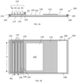
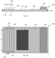
- FIGS. 1-5 illustrate embodiments of lateral flow devices for detecting analytes on a substrate, for detecting analytes bound to binding agents on a substrate, or for detecting analytes bound to binding agents on a wicking pad.
- a lateral flow device 100 includes a wicking pad 102 having a first end 104, a second end 106, two lateral edges 108, and a planar region 110 for contacting a substrate 112 (e.g., a membrane) comprising immobilized analytes or proteins (e.g., a Western blot, a dot blot) to be detected.
- the lateral flow device 100 also includes a support layer 114 and a top layer 116.
- the support layer 114 is bonded to a first planar surface 118 of the wicking pad 102.
- the top layer 116 is bonded to a second planar surface 120 of the wicking pad 102.
- the wicking pad 102 is sandwiched (e.g., is laminated) between the support layer 114 and the top layer 116.
- the top layer 116 partially covers and is bonded to the wicking pad 102 and prevents evaporation of fluids during use of the lateral flow device 100.
- the top layer 116 is bonded to the support layer 114 on the edges.
- One end of the top layer 116 comprises two or more reservoirs 122 spatially separated from each other.
- the longitudinal axis of each reservoir is perpendicular to the lateral edges 108 of the wicking pad 102 such that each reservoir is oriented perpendicular to the direction of lateral flow.
- the reservoirs 122 e.g., R1, R2, R3, and R4 are located at or near the first end 104 of the wicking pad 102 upstream from the planar region 110 for contacting the substrate 112.
- “near” is defined as no more than 10%, 20%, 30%, 40%, or 50% the length from the first end 104 of the wicking pad 102.
- Each of the reservoirs 122 is in fluid communication with the first end 104 of the wicking pad 102 (i.e., liquid, when present in the reservoirs 122, can flow from each of the reservoirs 122 into the wicking pad 102).
- the reservoirs 122 supply liquid (e.g., buffers and detection reagents) sequentially to the wicking pad 102 and into the planar region 110 for applying the substrate 112.
- the planar region 110 of the wicking pad 102 is located downstream from the reservoirs 122 and upstream from a pump 124 (i.e., between the reservoirs 122 and the pump 124).
- the reservoirs 122 comprise one set of four reservoirs.
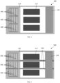
- the reservoirs comprise two or more sets 440, 540 of reservoirs spatially separated from each other (e.g., separated by a wall or a distance) such that multiple substrates can be analyzed at one time.
- the sets 440, 540 of reservoirs are adjacent to each other on the width axis of the lateral flow device 400, 500.
- the sets 440, 540 of reservoirs are arranged to run in parallel to each other in a side-by-side relationship. Each set of reservoirs is functionally independent of the adjacent set of reservoirs.
- each of the reservoirs 122 is bounded by a first wall 126 and a second wall 128 oriented perpendicular to the flow of liquid.
- Each of the reservoirs is further bounded by two end walls 130.
- the reservoirs share a wall.
- the second wall of a first reservoir R1 can be the first wall of a second reservoir R2.
- the reservoirs 122 can be pre-molded during manufacture of the top layer 116 or can be manufactured separately and then bonded directly to the top layer 116.
- each of the reservoirs 122 can be any size and shape.
- each of the reservoirs 122 comprises a length L1, a width W1, and a depth D1.
- each of the reservoirs is at least about 0.5, 1.0, 8.5, 13.5, 20 cm or more in at least one dimension.
- the length L1 and the width W1 of each of the reservoirs 122 are at least about 2-fold, 3-fold, 5-fold, 10-fold, 100-fold or more larger than the depth D 1.
- each of the reservoirs is sized to match the width of the wicking pad 102 and has a length L1 that is at least about 3-fold, 4-fold, 5-fold, 6-fold, 8-fold, 10-fold, 13-fold, 17-fold, 20-fold, 27-fold or more larger than the width W1.
- each reservoir includes about 0.5 cm x 0.5 cm, 0.5 cm x 1 cm, 0.5 cm x 8.5 cm, 1x3 cm, 3 cm x 3 cm, 2.5 cm x about 8.5 cm, 1 cm x 10 cm, 3 cm x 10 cm, 2 cm x 13.5 cm, 3 x 13.5 cm, 1 cm x 15 cm, 3 cm x 15 cm, or 3.5 cm x 20 cm in width W1and length L1, respectively.
- the "width W1" is based on the direction of flow and is the shortest dimension. In some embodiments, each reservoir is 3 cm in width W1 by 10 cm in length L1.
- each reagent reservoir is 1 ⁇ 0.5, 1, 2 or 3 cm in width W1 by 10 ⁇ 0.5 cm or 15 ⁇ 0.5 cm in length L1.
- the depth D1 of at least one reservoir is about 0.5 cm, about 1 cm, about 2 cm, or about 3 cm.
- Each of the reservoirs 122 comprises an aperture 132 (e.g., a slot) through which a solution is released from the reservoir and into the wicking pad 102.
- the slot can have a width W2 (e.g., a short dimension) ranging from about 0.1 mm to about 5 mm and a length L2 (e.g., a long dimension) ranging from about 0.5 cm to about 20 cm.
- the width W2 is 0.1 mm, 0.5 mm, 1 mm, 2 mm, 3 mm, 4 mm, or 5 mm.
- the length L2 is 8.5 cm, 9 cm, 9.5 cm, 13.5 cm, 15 cm, or 20 cm.
- each of the reservoirs 122 can be determined by many factors including, the size and shape of the reservoirs 122 and the configuration of the lateral flow device 100. In some embodiments, each reservoir has a capacity of at least about 0.25 ml to about 30 ml. In some embodiments, the thickness of the top layer 116 defines the volume of the reservoir. In certain embodiments, the thickness of the top layer 116 is 0.953 cm (3/8 inch) or 0.64 cm (1 ⁇ 4 inch) thick.
- the top layer 116 further comprises a first opening 136 through which the substrate is contacted to the planar region of the wicking pad downstream from the reservoirs ( FIGS. 1A - 2B ). In certain embodiments, the top layer 116 further comprises a second opening 138 through which the pump is contacted to the second planar surface of the wicking pad downstream from the first opening 136. In some embodiments ( FIGS. 3A - 3C ), the top layer 116 partially covers the wicking pad, i.e., only the reservoirs cover and are bonded to the wicking pad. In certain embodiments, no top layer is present downstream from the reservoirs, i.e., in the planar region on which the substrate and pump are applied. In some embodiments, the top layer 116 comprises an opening downstream from the reservoirs and the opening is of sufficient size to accommodate applying both the substrate 112 and the pump 124 to the wicking pad 102.
- the pump 124 is located on or near the second end 106 of and in intimate contact with the wicking pad 102.
- the dry pump 124 acts as a drain by wicking the liquid from the reservoirs 122 through the wicking pad 102.
- the planar region 110 of the wicking pad 102 can include drawings/markings or other indications for where a user should place the substrate 112 or where binding agents are immobilized in/on the wicking pad. Alternately, the drawing/markings can be on the support layer of the device.
- the wicking pad 102 has a width, a length, and a height (e.g., a thickness).
- the wicking pad 102 can be any size and shape.
- at least a section (e.g., the planar region 110 for applying the substrate 112) of the wicking pad 102 is planar.
- the length and the width of the wicking pad 102 are at least about 2-fold, 5-fold, 10-fold, 100-fold or more larger than the height ( i.e., thickness).
- Exemplary sizes for wicking pads include wicking pads that are at least about 0.25 cm, 0.5 cm, 1 cm, 2 cm, 3 cm, 4 cm, 5 cm, 6 cm, 7 cm, 8 cm, 10 cm, 12 cm, 15 cm, 20 cm, 25 cm, 30 cm or more in at least one dimension.
- the wicking pad 102 is 20 ⁇ 0.5, 1, 2, 3, 4, 5, 6, 9 or 10 cm in length (in the direction of flow) by 10 ⁇ 0.5, 1, 2, 3, 4, 5, 6, 7, 8, or 9 cm in width.
- the wicking pad 102 is an absorbent material.
- the wicking pad 102 is configured to have a high solution capacity and a lateral flow rate.
- the high solution capacity and lateral flow rate are provided by having a wicking pad 102 with substantial height ( e.g., thickness).
- the wicking pad 102 is about 10, 9, 8, 7, 6, 5, 4, 3, 2, 1, 0.75, 0.5, or about 0.2 mm thick.
- the wicking pad 102 is between about 0.05 mm and about 0.5 mm thick.
- the wicking pad 102 comprises one or more zones separated from each other by a hydrophobic or impermeable barrier 542 that is parallel to the lateral edges of the wicking pad ( FIG. 5 ).
- the barriers 542 inhibit, eliminate, or substantially eliminate fluid communication (e.g., fluid flow) between adjacent zones in the wicking pad and allow for simultaneous processing of multiple substrates.
- Hydrophobic barriers include wax barriers, or barriers created by vapor or liquid phase silanization of the wicking pad.
- Exemplary materials from which impermeable barriers can be formed include wax, plastic, polymers, and resin.
- each zone has its own pump 124.
- the wax used to form the wax barriers can be any wax that is flowable at elevated temperatures and non-flowable at ambient temperature (e.g., about 20-25 °C.).
- Examples are paraffin waxes, microcrystalline waxes, thermoset waxes, animal waxes such as beeswax, lanolin, and tallow, vegetable waxes such as soy, carnauba, candelilla and palm waxes, mineral waxes such as ceresin and montan waxes, petroleum waxes, and synthetic waxes such as ethylenic polymers, chlorinated naphthalenes, and Fischer-Tropsch waxes.
- Paraffin wax compositions may contain, in addition to n-paraffins and isoparaffins, minor amounts of cyclo-paraffins or olefins, or both.
- the silanization reagent used to form hydrophobic barriers can be any silanization reagent that reacts with the porous substrate, or a portion thereof.
- a silanization reagent that silanizes hydroxyl groups of the cellulose backbone can be utilized.
- Exemplary silanization reagents include trimethylchlorosilane, trimethylsilane, or hexamethyldisilazane.
- Silanization reagents further include triethoxysilanes (R-Si(C 2 HsO) 3 ) where R is, for example, vinyl, methacrylol, aminopropyl, fluoroalkyl, or thioethyl.
- R-Si(C 2 HsO) 3 triethoxysilanes
- R is, for example, vinyl, methacrylol, aminopropyl, fluoroalkyl, or thioethyl.
- R-Si(C 2 HsO) 3 triethoxy
- the wax or other barrier forming reagent can be applied to one side or both sides of the porous substrate, although in most cases, application to one side will be sufficient, provided that the porous substrate penetrates, or is made to penetrate (e.g., by melting after application), the porous substrate to a degree sufficient to serve as a barrier to the flow of liquid.
- the barrier forming reagent can be applied as a liquid.
- the liquid can be applied by hand or other apparatus. In some cases, the liquid is sprayed or poured onto the porous substrate. Spraying can be accomplished with an inkjet printer or similar apparatus. In some cases, the liquid hardens after application to form an impermeable and/or hydrophobic barrier.
- the barrier forming reagent can be applied as a vapor.
- a silanization reagent, wax, plastic, resin, or polymer can be applied as a vapor that condenses on the porous substrate or reacts with the porous substrate.
- the barrier forming reagent can be applied as a solid.
- wax can be applied as a solid manually or in an automated or mechanized fashion.
- the porous substrate is masked to protect regions from the barrier forming reagent, and the barrier forming reagent is contacted with the porous substrate.
- Wax pens are known in the art and commonly include a housing having a reservoir to contain hot wax, a spout, and a handle. Application of the hot wax is achieved by tipping the housing to cause the liquefied wax to pass through the spout, and the housing is equipped with a valve to stop the flow of the wax at the terminus of a printed line.
- Wax printers are likewise known in the art and commonly operated by thermal transfer printing using a print head that includes an array of very small heating elements that are software-controlled for independent activation to produce localized heating of the wax above its melting point to release the wax to the print medium.
- Commercially available examples of wax printers include the Phaser 8560DN (Fuji Xerox, Ltd., Japan), and the CALCOMP COLORMASTER PLUS thermal wax transfer printer (CalComp Graphics, LLC, Foothill Collins, Calif., USA). Descriptions of wax printers and their use can be found in Kroon (Tektronix, Inc.), US Patent 5,957,593 (Sep. 28, 1999 ); Lin (Xerox Corporation), US Patent 8,206,664 (Jun.
- Lu Y., et al., "Rapid prototyping of paper-based microfluidics with wax for low-cost, portable bioassay," Electrophoresis 2009, 30, 1497-1500 ; and Carrilho, E., et al., "Understanding Wax Printing: A Simple Micropatterning Process for Paper-Based Microfluidics," Anal. Chem., 2009, 81 (16), 7091-7095 .
- the width of a wax line as applied (prior to heating) can vary and is not critical to the present invention, provided that the amount of wax contained within the line is sufficient to penetrate the porous substrate and form a barrier to the lateral flow of fluid within the porous substrate.
- the wax can be made to penetrate the bulk thickness of the porous substrate to fill the pores or voids and form a lateral barrier to aqueous fluid flow by heating the wax above its melting point.
- the amount of wax applied will be such that full penetration of the thickness of the wicking pad with the melted wax will occur while lateral flow of the melted wax (i.e., in directions parallel to the flat faces of the sheet) is minimal or at least limited to a small distance that is substantially uniform along the length of a line of applied wax so that the resulting area bordered by the wax barrier is known and controlled.
- the formation of the barrier in this manner can also be controlled by the degree of heating, including the temperature to which the wax is heated and the length of time that the heating is continued.
- Optimal temperatures and durations are readily determinable by routine trial and error, but in most cases serviceable results will be obtained by heating to at least 5 °C above the wax melting point, and in many cases from about 5 to about 50 °C above the melting point, or from about 10 to about 30 °C above the melting point.
- the most appropriate heating time will depend on the temperature, higher temperatures requiring less time. In general, heating times ranging from about 15 s to about 20 min, or in many cases from about 30 s to about 10 min, will provide useful results.
- Heating can be achieved by conventional means, including radiative heating, conductive heating, convective heating, impulse heating, and microwave heating. Effective results can be achieved with equipment as simple as a hot plate or a conventional oven.
- Optimal widths for hydrophobic or impermeable barriers may vary with the dimensions of the area to be bordered by the barrier and with the thickness of the porous substrate and are readily determinable by routine testing. In most cases, the width will range from about 10 ⁇ m to about 5 mm, from about 30 ⁇ m to about 3 mm, from about 100 ⁇ m to about 1 mm, or from about 200 ⁇ m to about 5 mm, or 10 mm.
- the wicking pad 102 has one or more reagents (e.g., binding agents such as antibodies) immobilized or embedded therein in one or more sections (e.g., in one or more sections downstream from the reservoirs).
- the embedded reagents are generally embedded or bound and dried into the wicking pad such that the reagents remain immobile during fluid flow or such that the reagents are immobile until contacted by an aqueous fluid front under lateral flow and are released at a user-defined event.
- the sections can be printed lines or spots of reagent.
- the wicking pad 102 generally has a large surface area due to the presence of a plurality of pores or voids.
- the large surface area can increase the loading capacity of the wicking pad 102 for one or more reagents or one or more solutions containing a reagent.
- the wicking pad 102 has a specific surface area of at least about 0.001 m 2 /g, 0.02 m 2 /g, 0.1 m 2 /g, 0.5 m 2 /g, 1 m 2 /g, 10 m 2 /g, or more as measured by standard techniques.
- the wicking pad 102 can have a particular pore size, a particular average pore size, or a particular pore size range.
- the wicking pad 102 can contain 0.1 ⁇ m pores, 0.2 ⁇ m pores, 0.45 ⁇ m pores, or 1, 2, 4, 5, 6, 7, 8, 10, 15, 20 ⁇ m pores, or pores larger than about 20 ⁇ m.
- the wicking pad 102 can contain pores that average 0.1, 0.2, 0.45, 1, 2, 4, 5, 6, 7, 8, 10, 15, or 20 ⁇ m, or more in size.
- the wicking pad 102 can contain pores that range about 0.1-8 ⁇ m, 0.2-8 ⁇ m, 0.45-8 ⁇ m, 1-8 ⁇ m, 0.1-4 ⁇ m, 0.1-2 ⁇ m, 0.1-1 ⁇ m, 0.1-0.45 ⁇ m, 0.2-8 ⁇ m, 0.2-4 ⁇ m, 0.2-2 ⁇ m, 0.2-1 ⁇ m, 0.2-0.45 ⁇ m, 0.45-8 ⁇ m, 0.45-4 ⁇ m, 0.45-2 ⁇ m, 0.45-1 ⁇ m in size.
- the wicking pad 102 can contain pores that are less than about 20 ⁇ m in size.
- the wicking pad 102 can be composed of a material in which at least about 50%, 60%, 70%, 80%, 90% or more of the pores are less than about 20, 15, 10, or 5 ⁇ m in size.
- the pores in the wicking pad 102 are large enough to contain one or more proteins of average size (e.g., about 1 nm).
- the pores can be at least 1 nm in size, at least 5 nm in size, at least 10, 100, or 500 nm in size.
- at least 50%, 60%, 70%, 80%, 90% or more of the pores can be more than 1, 5, 10, 50, 100, or 500 nm in size.
- pore size can be measured as a radius or a diameter.
- the wicking pad 102 contains porous polyethylene, such as porous polyethylene having a pore size between 0.2 and 20 ⁇ m, or between 1 and 12 ⁇ m.
- the wicking pad 102 can have a different pore size in different regions of the pad.
- the wicking pad 102 can have a lateral flow region that has a different pore size or pore size range.
- pore size is chosen to control flow rate. For example, a larger pore size will allow for a faster flow rate.
- the wicking pad e.g, glass fiber or cellulose
- the edges of the wicking pad 102 have a water-tight seal 139 (see FIGS. 1A , 2A , 3A, and 3B ).
- the seal 139 is formed from water-tight material or with a heat seal to prevent liquid from leaking out of the edges during lateral flow.
- Exemplary water-tight materials that can be used to seal the edges of the wicking pad include acrylic (e.g., nail polish), wax, and photopolymers.
- the wicking pad 102 can be treated or functionalized to minimize non-specific reagent binding, increase lateral flow, increase wicking, or to reduce protein aggregation.
- the wicking pad 102, or a portion thereof can be treated to alter the hydrophilicity or alter the hydrophobicity of the treated area.
- altering the hydrophilicity or hydrophobicity of the wicking pad 102 can increase binding agent loading, decrease binding agent aggregation or denaturation, create mask regions in which binding agent is excluded from or not loaded, or direct flow of binding agents when the wicking pad is wet.
- the wicking pad contains a protein aggregation modifying agent as described herein.
- the wicking pad 102, and the pump are generally formed of a bibulous material and can be made out of, for example, natural fibers, synthetic fibers, glass fibers or blends thereof. Examples include nitrocellulose, cotton, glass, and combinations thereof. There are many commercial materials available for diagnostic uses from vendors including Ahlstrom, GE, PALL, Millipore, Sartorius, and S&S.
- the pump is formed from material having a liquid absorbing capacity that is significantly greater than the wicking pad 102 and that allows a faster rate of fluid flow than through the wicking pad 102.
- the pump is formed from one or more absorbent pads (e.g., a bibulous material).
- the bibulous material can include polymer containing material.
- the polymer can be in the form of polymer beads, a polymer membrane, or a polymer monolith. In some cases, the polymer is cellulose.
- Cellulose containing pads include paper, cloth, woven, or non-woven cellulose substrates. Cloth pads include those containing a natural cellulose fiber such as cotton or wool.
- Paper pads include those containing natural cellulose fiber (e.g., cellulose or regenerated cellulose) and those containing cellulose fiber derivatives including cellulose esters (e.g., nitrocellulose, cellulose acetate, cellulose triacetate, cellulose propionate, cellulose acetate propionate, cellulose acetate butyrate, and cellulose sulfate) and cellulose ethers (e.g., methylcellulose, ethyl cellulose, ethyl methyl cellulose, hydroxyethyl cellulose, hydroxyethyl methyl cellulose, hydroxypropyl methyl cellulose, ethyl hydroxyethyl cellulose, and carboxymethyl cellulose).
- the cellulose pads contain rayon.
- the pad is paper, such as a variety of WHATMAN ® paper.
- the bibulous material can also include a sintered material.
- the bibulous material can contain a sintered glass, a sintered polymer, or sintered metal, or a combination thereof.
- the sintered material is formed by sintering one or more of powdered glass, powdered polymer, or powdered metal.
- the sintered material is formed by sintering one or more of glass, metal, or polymer fibers.
- the sintered material is formed from the sintering of one or more of glass, polymer, or metal beads.
- the bibulous material can also contain, one or more non-cellulosic polymers, e.g. a synthetic polymer, a natural polymer, or a semisynthetic polymer.
- the material can contain a polyester, such as polyglycolide, polylactic acid, polycaprolactone, polyethylene adipate, polyhydroxyalkanoate, polyhydroxybutyrate, poly(3-hydroxybutyrate-co-3-hydroxyvalerate, polyethylene terephthalate, polybutylene terephthalate, polytrimethylene terephthalate, polyethylene naphthalate, Vectran ® .
- the polymer is spunbond, such as a spunbond polyester.
- Additional synthetic polymers include nylon, polypropylene, polyethylene, polystyrene, divinylbenzene, polyvinyl, polyvinyl difluoride, high density polyvinyl difluoride, polyacrylamide, a (C 2 - C 6 ) monoolefin polymer, a vinylaromatic polymer, a vinylaminoaromatic polymer, a vinyl-halide polymer, a (C 1 - C 6 ) alkyl (meth)acrylate polymer, a(meth)acrylamide polymer, a vinyl pyrrolidone polymer , a vinyl pyridine polymer, a (C 1 - C 6 ) hydroxyalkyl (meth)acrylate polymer, a (meth)acrylic acid polymer, an acrylamidomethylpropylsulfonic acid polymer, an N-hydroxy-containing (C 1 - C 6 ) alkyl(meth)acrylamide polymer, acrylonitrile or a mixture
- the substrate 112 is generally planar in shape and can be, for example, a membrane formed of nitrocellulose, polyvinylidene fluoride, nylon, or polysulfone.
- Other materials from which the substrate 112 can be formed include glass, plastic, silicon, metal, and/or metal oxide that is bare or is functionalized with polymers.
- Plastic materials from which the substrate 112 can be formed include polyethylene terephthalate, polypropylene, polystyrene, and/or polycarbonate.
- polymers with which to functionalize the surface of substrates formed from plastic, glass, metal or metal oxide include glycidoxypropyltriethoxysilane, poly-L-lysine, polybrene, polyethylene glycol polymers, dextran polymer, aminopropylsilane, caroxysilane, hydrogels and polymer brushes, and/or self-assembled monolayers of e.g. functionalized alkyl thiols, dendrimers or oligonucleotides.
- Exemplary bonding methods to bond the support layer and all or portions of the top layer to the wicking pad include bonding with an adhesive, thermal bonding, and organic solvent bonding with or without pressure.
- adhesive the nature of the adhesive may affect the assay performance (i.e., flow characteristics, reagent stability) and can be optimized for the desired assay or application.
- the adhesive may be part of the support layer of the device 100.
- Exemplary adhesives include spray adhesive, ultraviolet light curable adhesive, or pressure sensitive adhesive.
- the support layer and/or the top layer is formed from a liquid impermeable material (e.g., plastic) including polyethylene terephthalate, polyethylene terephthalate glycol-modified, polypropylene, polystyrene, and polycarbonate.
- a liquid impermeable material e.g., plastic
- the support layer and/or the top layer can, for example, be vacuum or injection molded or otherwise constructed.
- Binding agents are described herein for detection of analytes.
- the binding agents are antibodies (e.g., primary or secondary antibodies).
- Primary antibodies can be used to bind to an analyte.
- the primary antibody is labeled, enabling detection of the primary antibody and subsequent detection of the analyte.
- the primary antibody is detected by binding to a labeled secondary binding agent, such as a labeled secondary antibody.
- tertiary binding agents are utilized to detect complexes containing the analyte and the primary and secondary binding agent.
- Binding agents can be provided in one or more reagent solutions.
- the reagent solutions can contain one of more buffers, salts, density agents, or protein aggregation modifying agents as described herein.
- Density agents can be used to modulate the viscosity of the reagent solution which will modulate the rate of solution flow out of the reservoirs. Having a density agent in each of the reagent solutions can also enhance binding interactions between, e.g., the analytes immobilized on the substrate and the binding agents (e.g., antibodies). Examples of density agents include glycerol, sucrose, trehalose, dextran, and polyethylene glycol.
- the binding agent(s) can be stored in solution for at least about a day, three days, 7-10 days, at least about a month, two months, three months, six months, a year or longer.
- Binding agents can also be provided on or in the wicking pad. For example, lines or spots of binding agents can be immobilized in/on the wicking pad downstream from the reservoir (e.g., in planar region 110).
- a first binding agent is a reversibly immobilized labeled first primary antibody (e.g., a primary antibody conjugate) for detection
- a second binding agent is an irreversibly immobilized unlabeled second primary antibody (e.g., a "test" primary antibody) for capture
- a third binding agent is a control antibody that binds to the first primary antibody.
- a control antibody can be used to assess assay validity.
- the labeled first primary antibody is paired with the second primary antibody and the two antibodies bind to different epitopes on the analyte in such a way that the analyte, if present, is sandwiched in between the first primary antibody and second primary antibody during the lateral flow assay.
- multiple matched pairs of first and second primary antibodies are immobilized on the wicking pad to allow for multiplex detection of analytes in the sample.
- a planar region of the wicking pad in fluid communication with fluid in one or more reservoirs contains one or more binding agents dried thereon.
- the dried binding agent(s) can be reconstituted by contacting the planar region of the wicking pad with an aqueous solution.
- the aqueous reconstitution buffer can contain one or more re-wetting reagents including salts, buffers, or a protein aggregation modifying agent as described herein.
- the binding agent (s) can be stored dry or substantially dry in the wicking pad for at least about a day, three days, 7-10 days, at least about a month, two months, three months, six months, a year or longer.
- Analytes can be detected by detecting a label that is linked to a binding agent.
- the label can be linked directly to the binding agent (e.g., by a covalent or other bond to the primary antibody) or the attachment can be indirect ( e.g., using a chelator or linker molecule).
- label and “detectable label” are used synonymously herein.
- each label e.g., a first label linked to a first binding agent, a second label linked to a second binding agent
- the signals e.g., a first signal generated by the first label, a second signal generated by the second label
- the two or more binding agent labels comprise the same type of agent (e.g., a first label that is a first fluorescent agent and a second label that is a second fluorescent agent). In some embodiments, the two or more binding agent labels (e.g., the first label, second label) combine to produce a detectable signal that is not generated in the absence of one or more of the labels.
- detectable labels examples include biotin/streptavidin labels, nucleic acid (e.g., oligonucleotide) labels, chemically reactive labels, fluorescent labels, enzyme labels, radioactive labels, quantum dots, polymer dots, mass labels, colloidal gold, electrochemical labels and combinations thereof.
- the label can include an optical agent such as a chromophore, fluorescent agent, phosphorescent agent, chemiluminescent agent, or an electrochemiluminescent agent.
- Chromophores include co-enzymes or co-factors that have a detectable absorbance.
- a binding agent can be detected by detecting the intrinsic absorbance of a peptide bond at 220 nm or the composite amino acid absorbance at 280 nm.
- Fluorescent agents can include a variety of organic and/or inorganic small molecules or a variety of fluorescent proteins and derivatives thereof.
- fluorescent agents can include cyanines, phthalocyanines, porphyrins, indocyanines, rhodamines, phenoxazines, phenylxanthenes, phenothiazines, phenoselenazines, fluoresceins (e.g., FITC, 5-carboxyfluorescein, and 6-carboxyfluorescein), benzoporphyrins, squaraines, dipyrrolo pyrimidones, tetracenes, quinolines, pyrazines, corrins, croconiums, acridones, phenanthridines, rhodamines (e.g., TAMRA, TMR, and Rhodamine Red), acridines, anthraquinones, chalcogenopyr
- a fluorescent agent is an Alexa Fluor dye, a DyLight dye, or an IRDye.
- a fluorescent agent is a polymer dot or a quantum dot.
- Fluorescent dyes and fluorescent label reagents include those which are commercially available, e.g., from Invitrogen/Molecular Probes (Eugene, OR), Pierce Biotechnology, Inc. (Rockford, IL), and Licor Biosciences (Lincoln, NE).
- the optical agent is an intercalating dye.
- 2, 3, 4, 5, or more binding agents are each labeled with an optical agent such as a fluorescent agent (e.g., a first binding agent labeled with a first fluorescent label, a second binding agent labeled with a second fluorescent label), and each binding agent that is labeled with an optical agent is detected by detecting a signal generated by the optical agent (e.g., a fluorescent signal generated by a fluorescent label).
- the second fluorescent label quenches a fluorescent signal generated by the first fluorescent label.
- the first and second fluorescent labels are members of a fluorescence resonance energy transfer (FRET) pair.
- FRET fluorescence resonance energy transfer
- FRET fluorescence resonance energy transfer
- Suitable FRET pairs include EDANS/fluorescein, IAED ANS/fluorescein, fluorescein/tetramethylrhodamine, fluorescein/LC Red 640, fluorescein/Cy 5, fluorescein/Cy 5.5, and fluorescein/LC Red 705.
- all of the binding agents are labeled with an optical agent, and each optical agent-labeled binding agent is detected by detecting a signal generated by the optical agent.
- the label is a radioisotope.
- Radioisotopes include radionuclides that emit gamma rays, positrons, beta and alpha particles, and X-rays. Suitable radionuclides include 225 Ac, 72 As, 211 At, 11 B, 128 Ba, 212 Bi, 75 Br, 77 Br, 14 C, 109 Cd, 62 Cu, 64 Cu, 67 Cu, 18 F, 67 Ga, 68 Ga, 3 H, 166 H, 123 I, 124 I, 125 I, 130 I, 131 I, 111 In, 177 Lu, 13 N, 15 O, 32 P, 33 P, 212 Pb, 103 Pd, 186 Re, 188 Re, 47 Sc, 153 Sm, 89 Sr, 99m Tc, 88 Y and 90 Y.
- 2, 3, 4, 5, or more binding agents are each labeled with a radioisotope (e.g., a first binding agent labeled with a first radioisotope, a second binding agent labeled with a second radioisotope), and each binding agent that is labeled with a radioisotope is detected by detecting radioactivity generated by the radioisotope.
- a radioisotope e.g., a first binding agent labeled with a first radioisotope, a second binding agent labeled with a second radioisotope
- each binding agent that is labeled with a radioisotope is detected by detecting radioactivity generated by the radioisotope.
- one binding agent can be labeled with a gamma emitter and one binding agent can be labeled with a beta emitter.
- the binding agents can be labeled with radionuclides that emit the same particle ( e.g., alpha, beta, or gamma)
- the label is an enzyme
- the binding agent is detected by detecting a product generated by the enzyme.
- suitable enzymes include urease, alkaline phosphatase, (horseradish) hydrogen peroxidase (HRP), glucose oxidase, beta-galactosidase, luciferase, alkaline phosphatase, and an esterase that hydrolyzes fluorescein diacetate.
- a horseradish-peroxidase detection system can be used with the chromogenic substrate tetramethylbenzidine (TMB), which yields a soluble product in the presence of hydrogen peroxide that is detectable at 450 nm, or a chemiluminescent substrate (e.g., Clarity from Bio-Rad Laboratories), which yields detectable light.
- TMB tetramethylbenzidine
- An alkaline phosphatase detection system can be used with the chromogenic substrate p-nitrophenyl phosphate, which yields a soluble product readily detectable at 405 nm.
- a ⁇ -galactosidase detection system can be used with the chromogenic substrate o-nitrophenyl- ⁇ -D-galactopyranoside (ONPG), which yields a soluble product detectable at 410 nm.
- a urease detection system can be used with a substrate such as urea-bromocresol purple (Sigma Immunochemicals; St. Louis, MO). In some cases, the enzyme acts on a fluorogenic substrate to generate a detectable fluorescent product.
- 2, 3, 4, 5, or more binding agents are each labeled with an enzyme (e.g., a first binding agent labeled with a first enzyme, a second binding agent labeled with a second enzyme), and each binding agent that is labeled with an enzyme is detected by detecting a product generated by the enzyme.
- all of the binding agents are labeled with an enzyme, and each enzyme-labeled binding agent is detected by detecting a product generated by the enzyme.
- the label is an affinity tag.
- suitable affinity tags include biotin, peptide tags (e.g., FLAG-tag, HA-tag, His-tag, Myc-tag, S-tag, SBP-tag, Strep-tag, eXact-tag), and protein tags (e.g., GST-tag, MBP-tag, GFP-tag).
- the label is a nucleic acid label.
- suitable nucleic acid labels include oligonucleotide sequences, single-stranded DNA, double-stranded DNA, RNA (e.g., mRNA or miRNA), DNA-RNA hybrids, or artificial nucleic acid analogs (e.g., LNA, PNA).
- the nucleic acid label is about 10, 15, 20, 25, 30, 35, 40, 45, 50, 60, 70, 80, 90, 100, 150, 200, 250, 300, 350, 400, 450, 500, 600, 700, 800, 900, or 1000 nucleotides in length.
- the nucleic acid label is an amplified nucleic acid (e.g, by PCR or by isothermal polymerase extension).
- a label or labels are incorporated into a nucleic acid label using a polymerase, reverse transcriptase, ligase, or other enzymes that act on nucleic acids (e.g., fluorescently modified nucleotides, biotin-nucleotides, digoxigenin -nucleotides, hapten nucleotides).
- the nucleic acid label is ligated to another label (e.g., a nucleic acid) to create a detectable product (e.g, proximity ligation assays).
- the label is a nucleic acid barcode.
- a "barcode” is a short nucleotide sequence (e.g., at least about 4, 6, 8, 10, or 12, nucleotides long) that uniquely defines a labeled molecule, or a second molecule bound to the labeled binding agent.
- the length of the barcode sequence determines how many unique samples can be differentiated. For example, a 4 nucleotides barcode can differentiate 4 4 or 256 samples or less, a 6 nucleotide barcode can differentiate 4096 different samples or less, and an 8 nucleotide barcode can index 65,536 different samples or less.
- the label is a "click" chemistry moiety.
- Click chemistry uses simple, robust reactions, such as the copper-catalyzed cycloaddition of azides and alkynes, to create intermolecular linkages.
- a click chemistry moiety e.g., an azide or alkyne moiety
- another detectable label e.g., a fluorescently labeled, biotinylated, or radiolabeled alkyne or azide moiety.
- two or more labels combine to produce a detectable signal that is not generated in the absence of one or more of the labels.
- each of the labels is an enzyme, and the activities of the enzymes combine to generate a detectable signal that is indicative of the presence of the labels (and thus, is indicative of each of the labeled proteins).
- Examples of enzymes combining to generate a detectable signal include coupled assays, such as a coupled assay using hexokinase and glucose-6-phosphate dehydrogenase; and a chemiluminescent assay for NAD(P)H coupled to a glucose-6-phosphate dehydrogenase, beta-D-galactosidase, or alkaline phosphatase assay. See, e.g., Maeda et al., J Biolumin Chemilumin 1989, 4:140-148 .
- Protein aggregation modifying agents can be utilized to reduce or eliminate aggregation or denaturation of binding agents, such as proteins (e.g., antibodies), stored in or delivered from a reagent solution, or the wicking pad 102.
- binding agents such as proteins (e.g., antibodies)
- protein aggregation modifying agents can be utilized to reduce or eliminate aggregation or denaturation of primary antibodies stored in/ delivered from the reagent solutions or the wicking pad 102.
- protein aggregation modifying agents can be utilized to facilitate lateral flow of binding agents in the planar region 110 of the wicking pad 102 or to reduce background on the substrate 112.
- protein aggregation modifying agents that act to displace proteins from the air-water interface and thereby protect them from denaturation and aggregation are particularly effective in reducing the aggregation of binding agents immobilized on the wicking pad 102.
- the protein aggregation modifying agent directly affects the stability of the binding agent by binding to the binding agent and/or stabilizing the binding agent.
- the protein aggregation modifying agent acts to shift the equilibrium away from a denatured or unfolded state and thus reduce aggregation.
- the interaction between the protein aggregation modifying agent and the binding agent is thermodynamically disfavored due to strong repulsion between an amide backbone of the binding agent and the protein aggregation modifying agent.
- unfolding of the binding agent in the presence of the protein aggregation modifying agent is disfavored because unfolding exposes more amide backbone surface to the protein aggregation modifying agent.
- Protein aggregation modifying agents can be one or more of a cyclodextrin, a non-ionic surfactant, an ionic surfactant, a zwitterionic surfactant, a non-detergent sulfobetaine, a simple sugar, a polysaccharide, a polyol, an organic solvent, an aggregation modifying protein, a disordered peptide sequence, an amino acid, an oxido-reduction agent, a lyoprotectant, a cryoprotectant, or a chaotropic agent.
- Cyclodextrins can be ⁇ -cyclodextrin, ⁇ -cyclodextrin, ⁇ -cyclodextrin, (2,3,6-tri-O-methyl)- ⁇ -cyclodextrin, (2,3,6-tri-O-methyl)- ⁇ -cyclodextrin, (2-hydroxy)propyl- ⁇ -cyclodextrin, (2-hydroxy)propyl- ⁇ -cyclodextrin, random methyl- ⁇ -cyclodextrin, random methyl- ⁇ -cyclodextrin, carboxymethyl- ⁇ -cyclodextrin, carboxymethyl- ⁇ -cyclodextrin, 6-monodeoxy-6-monoamino- ⁇ -cyclodextrin, sulfobutyl- ⁇ -cyclodextrin, 6-amino-6-deoxy- ⁇ -cyclodextrin, acetyl ⁇ -cyclodextrin, succinyl ⁇ -cyclodextrin,
- Cyclodextrins can also be a cyclodextrin polymer containing one or more of the foregoing cyclodextrin molecules. Additional cyclodextrins are known in the art, and include, e.g. those described on the world wide web at cyclodextrin.com. Exemplary concentrations of cyclodextrins are about 1 mM, 2 mM, 2.5 mM, 5 mM, 7.5 mM, 10 mM, 15 mM, 20 mM, 25 mM, 50 mM, 75 mM, or 100 mM.
- Non-ionic surfactants can be polyethylene-sorbitan-fatty acid esters, polyethylene-polypropylene glycols or polyoxyethylene-stearates.
- Polyethylene-sorbitan-fatty acid esters can be polyethylene(20)-sorbitan-esters (Tween 20 TM ) or polyoxyethylene(20)-sorbitanmonooleate (Tween 80 TM ).
- Polyethylene-polypropylene glycols can be polyoxypropylene-polyoxyethylene block copolymers such as those sold under the names Pluronic ® or Poloxamer TM .
- Polyoxyethylene-stearates can be, for example, those sold under the trademark Myrj TM .
- Exemplary, polyoxyethylene monolauryl ethers include those sold under the trademark Brij TM , e.g., Brij-35.
- Exemplary concentrations of non-ionic surfactants are about 0.01%, 0.02%, 0.05%, 0.1%, 0.2%, 0.5%, 0.75%, 1%, 2%, 2.5%, 5%, 7.5%, or about 10% w/w, w/v, or v/v.
- Ionic surfactants can be anionic surfactants or cationic surfactants.
- Anionic surfactants useful in the present invention can be soaps including alkali soaps, such as sodium, potassium or ammonium salts of aliphatic carboxylic acids, usually fatty acids, such as sodium stearate.
- Additional anionic surfactants include organic amine soaps such as organic amine salts of aliphatic carboxylic acids, usually fatty acids, such as triethanolamine stearate.
- Cationic surfactants useful in the present invention include amine salts such as octadecyl ammonium chloride or quarternary ammonium compounds such as benzalkonium chloride.
- Ionic surfactants can include the sodium, potassium or ammonium salts of alkyl sulfates, such as sodium dodecyl sulfate or sodium octyl sulfate.
- concentrations of ionic surfactants are about 0.01%, 0.02%, 0.05%, 0.1%, 0.2%, 0.5%, 0.75%, 1%, 2%, 2.5%, 5%, 7.5%, or about 10% w/w, w/v, or v/v.
- Zwitterionic surfactants have both cationic and anionic centers attached to the same molecule.
- the cationic part is, e.g., based on primary, secondary, or tertiary amines or quaternary ammonium cations.
- the anionic part can be a sulfonate, as in CHAPS (3-[(3-Cholamidopropyl)di-methylammonio]-1-propanesulfonate).
- Other anionic groups are sultaines illustrated by cocamidopropyl hydroxysultaine or betaines, e.g., cocamidoethyl betaine, cocamidopropyl betaine, or lauramidopropyl betaine.
- concentrations of zwitterionic surfactants are about 0.01%, 0.02%, 0.05%, 0.1%, 0.2%, 0.5%, 0.75%, 1%, 2%, 2.5%, 5%, 7.5%, and about 10% w/w, w/v, or vivo
- Non detergent sulfobetaines have a sulfobetaine hydrophilic group and a short hydrophobic group that cannot aggregate to form micelles, therefore NDSBs are not considered detergents.
- Exemplary NDSBs include NDSB 256, NDSB 221, NDSB 211, NDSB 201, NDSB 195, 3-(4-tert-Butyl-1-pyridinio)-1-propanesulfonate, 3-(1-pyridinio)-1-propanesulfonate, 3-(Benzyl-dimethylammonio) propanesulfonate, or Dimethylethylammoniumpropane sulfonate.
- Exemplary concentrations of NDSBs include about 0.01%, 0.02%, 0.05%, 0.1%, 0.2%, 0.5%, 0.75%, 1%, 2%, 2.5%, 5%, 7.5%, and about 10% w/w, w/v, or v/v.
- Polyols are compounds with multiple hydroxyl functional groups.
- polyols can modify the aggregation or denaturation behavior of a protein by a variety of mechanisms. For example, in some cases, the polyol can shift the equilibrium to the folded state by presenting a thermodynamically disfavored interaction with the protein backbone. Alternatively, in some cases, the polyol can bind to and stabilize the folded state of the protein.
- Polyols can be simple sugars such as sucrose, mannitol, sorbitol, inositol, xylitol, erythritol, glucose, galactose, raffinose, or trehalose. Polyols can also be polysaccharides such as dextran, starch, hydroxyethyl starch, or polymers containing one or more of the simple sugars described herein. Glycerol, ethylene glycol, polyethylene glycol, pentaerythritol propoxylate, and pentaerythritol propoxylate, and combinations thereof are also exemplary polyols.
- Organic solvents can be those organic solvent that are known to inhibit denaturation, unfolding, or aggregation of one or more proteins.
- suitable organic solvents are known in the art.
- organic solvents can include ethanol, butanol, propanol, phenol, dimethyl formamide, 2-methyl-2,4-pentanediol, 2,3-butanediol, 1,2-propanediol, 1,6-hexanediol, or dimethyl sulfoxide.
- Aggregation modifying proteins can be proteins known in the art to inhibit denaturation, unfolding, or aggregation of one or more proteins.
- Exemplary aggregation modifying proteins include albumins, protein chaperones, and heat shock proteins.
- Albumins are proteins that are water-soluble, are moderately soluble in concentrated salt solutions, and experience heat denaturation.
- Exemplary albumins include serum albumins (e.g., bovine, horse, or human serum albumin) or egg albumin (e.g., hen egg-white albumin).
- Other exemplary aggregation modifying proteins include casein, gelatin, ubiquitin, lysozyme, or late embryogenesis abundant (LEA) proteins.
- LEA proteins include LEA I, LEA II, LEA III, LEA IV, LEA V, or atypical LEA proteins. LEA proteins are known in the art and described, e.g., in Goyal K., et al., Biochemical Journal 288(pt. 1), 151-57, (2005 ).
- Protein aggregation modifying agents can also be amino acids.
- the amino acids can serve an oxido-reduction function to maintain an appropriate oxidative potential for the protein immobilized on the substrate 112.
- Suitable oxido-reductive amino acids include cysteine and cystine.
- Other amino acids serve to reduce denaturation or aggregation through a non-oxido-reductive method. For example, arginine, glycine, proline, and taurine have been shown to reduce protein aggregation.
- Oxido-reduction agents can be employed to reduce protein aggregation.
- Oxido-reductants other than cysteine and cystine can be used to optimize the reduction potential in the substrate 112 onto which the protein is immobilized.
- Exemplary oxido-reductants include mercaptoethanol, dithiothreitol, dithioerythritol, tris(2-carboxyethyl)phosphine, glutathione, glutathione disulfide, and oxidized derivatives thereof, as well as Cu 2+ .
- Protein aggregation modifying agents can also include lyoprotectants, cryoprotectants, or chaotropic agents.
- the protein aggregation modifying agent is a chaotrope such as urea, thiourea, guanidinium, cyanate, thiocyanate, trimethylammonium, tetramethylammonium, cesium, rubidium, nitrate, acetate, iodide, bromide, trichloroacetate, or perchlorate. Under certain conditions, such as at low concentrations, chaotropes can reduce protein aggregation.
- Other protein aggregation modifying agents include trimethylamine N-oxide.
- Protein aggregation modifying agents can be salts.
- Exemplary salts include the sodium, potassium, magnesium, or calcium salts of chloride, sulfate, or phosphate.
- Protein aggregation modifying agents can also be buffering agents.
- Exemplary buffering agents include tris (hydroxymethyl) amino methene (TRIS), TAPSO, MES, HEPES, PIPES, CAPS, CAPSO, MOPS, MOPSO, or sodium or potassium phosphate, carbonate, bicarbonate, citrate, acetate, or borate buffers.
- the protein aggregation modifying agents can be provided in any suitable concentration.
- the protein is provided as an aqueous solution containing binding agent and protein aggregation modifying agents.
- the solution can be contacted with the wicking layer and, optionally, dried.
- Exemplary concentrations of protein aggregation modifying agents in the aqueous binding agent solution include about 0.001%, 0.005%, 0.01%, 0.05%, 0.1%, 0.5%, 1%, 2%, 4%, 5%, 10%, 20%, or about 25% or more w/v of the solution.
- concentrations include about 1 ⁇ M, 5 ⁇ M, 10 ⁇ M, 25 ⁇ M, 50 ⁇ M, 75 ⁇ M, 100 ⁇ M, 150 ⁇ M, 200 ⁇ M, 300 ⁇ M, 500 ⁇ M, 750 ⁇ M, 1 mM, 5 mM, 10 mM, 25 mM, 50 mM, 100 mM, 150 mM, 200 mM, 300 mM, 500 mM, and 1 M.
- the protein aggregation modifying agents are provided in the reagent solution.
- Exemplary compositions containing a protein aggregation modifying agent contain about 0.001%, 0.005%, 0.01%, 0.05%, 0.1%, 0.5%, 1%, 2%, 3%, 4%, 5%, or about 10%, 20%, or about 25% by weight of one or more protein aggregation modifying agents.
- Protein aggregation modifying agents can be provided in any suitable combination. For example, in some cases, 1, 2, 3, 4, 5, 6, 7, 8, 9, 10 or more of the foregoing protein aggregation modifying agents can be utilized to reduce aggregation of a binding agent reversibly immobilized on the wicking pad.
- the wicking pad prior to contacting the wicking pad with the binding agent solution, the wicking pad contains a protein aggregation modifying agent, and the binding agent solution contains the same, or a different, protein aggregation modifying agent.
- the wicking pad prior to contacting the wicking pad with the binding agent solution, the wicking pad contains a protein aggregation modifying agent, and the binding agent solution does not contain a protein aggregation modifying agent.
- the binding agent solution prior to contacting the wicking pad with the binding agent solution, the binding agent solution contains a protein aggregation modifying agent and the wicking pad, or the region to be contacted, does not.
- the method comprises contacting a substrate 112 (e.g., a Western blot) having immobilized analytes or binding agent(s) within or on the wicking pad 102, which can be supplied pre-moistened or can be pre-moistened by the user with, for example, lateral flow buffer.
- a substrate 112 e.g., a Western blot
- the substrate 112 is placed face down on the wicking pad 102 through an opening in the top layer 116 downstream from the reservoirs and upstream from the pump 124 (e.g., between the reservoirs and the pump or in the planar region 110 of the wicking pad 102).
- a different reagent solution is next applied to each of the reservoirs starting with a first reservoir R1 closest to the region 110 for contacting the substrate 112.
- the reagent solutions can be applied to the reservoirs sequentially or simultaneously.
- the reagent solutions can also be applied to the reservoirs in any order.
- four different reagent solutions e.g., primary antibody, first wash solution, secondary antibodies or secondary detection reagents, and second wash solution
- four different reagent solutions are applied to the reservoirs.
- a different or the same set of four reagent solutions is applied to each set of reservoirs, depending on the analytes or binding agents immobilized on the substrate 112.
- a first reagent solution having labeled primary antibody is applied to a first reservoir R1 and a second reagent solution having a first wash solution is applied to a second reservoir R2.
- four different reagent solutions are applied to the reservoirs in the following order: the first reagent solution having primary antibody is applied to the first reservoir R1, the second reagent solution having a first wash solution is applied to the second reservoir R2, a third reagent solution having a secondary antibody or a secondary detection reagent is applied to a third reservoir R3, and a fourth reagent solution having a second wash solution is applied to a fourth reservoir R4.
- the reagent solution applied to the reservoir has at least twice the volume of another reagent solution.
- the volume of the second wash solution in the fourth reservoir R4 can be at least twice the volume of the secondary antibody in the third reservoir R3.
- the fourth reagent solution having the second wash solution is omitted to allow the secondary antibody or secondary detection reagent in the third reservoir R3 more time to bind to the primary antibody.
- a sample with an analyte is applied to the first reservoir R1
- a first wash solution is applied to the second reservoir R2
- a secondary detection reagent is applied to the third reservoir R3 and, if needed, a second wash solution is applied to the fourth reservoir R4.
- a different solution e.g., a sample or a reagent solution is applied to at least two of the reservoirs.
- a line of labeled reversibly immobilized first primary antibodies e.g, a primary antibody conjugate
- a line of unlabeled irreversibly immobilized second primary antibodies e.g., test primary antibodies
- a line of irreversibly immobilized control antibodies that bind to the first primary antibodies is printed on the planar region 110 of the wicking pad 102, a sample having one or more analytes and optionally a control protein is applied to the first reservoir R1 and a wash solution (e.g., lateral flow buffer) is applied to the second reservoir R2.
- a wash solution e.g., lateral flow buffer
- a detection reagent e.g., labeled primary antibody
- a second wash solution is applied to the fourth reservoir R4.
- a labeled primary antibody is applied to the first reservoir R1 and a first wash solution is applied to the second reservoir R2. If needed, a secondary detection reagent is applied to the third reservoir R3 and a second wash solution is applied to the fourth reservoir R4.
- the reagent solutions and/or sample are then allowed to flow sequentially from the reservoirs onto the planar region 110 of the wicking pad 102.
- the lateral flow e.g., the progress
- each of the reagent solutions out of the reservoirs 122 and into/through the wicking pad 102 is monitored visually with one or more dyes or indicators in each of the reagent solutions.
- the reagent solutions are pulled by wicking from the reservoirs into the wicking pad and to the dry pump, carrying the reagents (e.g., the primary antibody, the first wash solution, and if needed, secondary antibodies and the second wash solution) in the reagent solutions sequentially by lateral flow into contact with the substrate 112 having proteins or analytes immobilized thereon.
- the primary antibodies in the first reagent solution are transported in the wicking pad 102, contact the proteins or analytes on the substrate 112, and bind to the target proteins or analytes, if present, on the substrate 112.
- lateral flow of the reagent solutions/lateral flow buffer from the reservoirs to the pump further allows the first wash solution in the second reagent solution to be transported in the wicking pad 102 such that unbound primary antibodies are removed from the substrate 112.
- lateral flow of the reagent solutions/ lateral flow buffer from the reservoirs to the pump further allows the secondary antibodies or a secondary detection reagent in the third reagent solution to be transported in the wicking pad 102 and to contact the primary antibodies bound to target proteins, if present, on the substrate 112.
- lateral flow of the reagent solutions/lateral flow buffer from the reservoirs to the pump further allows the second wash solution in the fourth reagent solution to be transported in the wicking pad 102 such that unbound secondary antibodies are removed from the substrate 112.
- the volume of the second wash solution applied to and transported in the wicking pad 102 is twice the volume of secondary antibody applied to and transported in the wicking pad 102.
- the sample and reagent solutions are pulled by wicking from the reservoirs into the wicking pad and to the dry pump, carrying the analytes (and optional control protein) in the sample and the reagents (e.g., the first wash solution, the secondary detection reagent and, if needed, the second wash solution) in the reagent solutions sequentially by lateral flow into contact with the substrate 112.
- the sample is a biological sample.
- Biological samples can be obtained from any biological organism, e.g., an animal, plant, fungus, bacterial, or any other organism.
- the biological sample is from an animal, e.g., a mammal (e.g., a human or a non-human primate, a cow, horse, pig, sheep, cat, dog, mouse, or rat), a bird (e.g., chicken), or a fish.
- a mammal e.g., a human or a non-human primate, a cow, horse, pig, sheep, cat, dog, mouse, or rat
- a bird e.g., chicken
- a biological sample can be any tissue or bodily fluid obtained from the biological organism, e.g., blood, a blood fraction, or a blood product (e.g., serum, plasma, platelets and red blood cells), sputum or saliva, tissue (e.g., kidney, lung, liver, heart, brain, nervous tissue, thyroid, eye, skeletal muscle, cartilage, or bone tissue); cultured cells, e.g., primary cultures, explants, transformed cells, stem cells, stool, or urine.
- the sample includes a positive control protein for assessing assay validity or for normalizing the test signal across a multiplicity of different antibody zones.
- the sample and reagent solutions are pulled by wicking from the reservoirs into the wicking pad and to the dry pump, carrying the analytes in the sample and the reagents (e.g., the first wash solution and, if needed, the secondary detection reagent and the second wash solution) in the reagent solutions sequentially by lateral flow into contact with the region 110.
- the reagents e.g., the first wash solution and, if needed, the secondary detection reagent and the second wash solution
- a substantially uniform pressure is applied to the pump to improve contact of the pump with the wicking pad 102.
- a weight can be placed on top of the pump to urge the pump toward the wicking pad 102.
- a cover can be placed onto the device once the reagent solutions have been applied to the reservoirs to minimize evaporation and to apply even pressure to the pump 124.
- the cover can be placed loosely on top of the device and then the device with the cover can be placed into a drawer-like container that slides into a box.
- a sponge Prior to placing the cover on the device or in place of the cover, a sponge can be placed on the pump to aide in applying even pressure to the pump. The process requires minimal user interaction with the consumable.
- the binding of primary antibodies to the target proteins is followed visually or by using a detector.
- the substrate (s) is/are removed from the lateral flow device 100 and the binding of the primary antibodies to the target proteins, if present, is detected.
- the antibody binding to the target protein is visualized and/or detected through the use of detectable moieties and/or labels as described herein. Suitable labels and/or moieties are detected by spectroscopic, photochemical, biochemical, immunochemical, isotopic, electrical, optical, chemical, or mass spectrometric techniques.
- the binding of the analyte, if present, to the first primary antibody and to the second primary antibody is followed visually or by using a detector.
- the binding of the analyte to the first and second primary antibodies is visualized and/or detected through the use of detectable moieties and/or labels as described herein.
- absorbent bibulous pad materials There are many absorbent bibulous pad materials, wick pad materials, and antibody application materials known in the art, the selection from which can be made to control the volume, to control the flow rate of the system, to ensure even flow, and to ensure complete delivery of antibodies/reagents from the reservoirs.
- Other methods that affect the timing of reagent/antibody delivery such as using torturous paths in the wick pad are possible.
- Still other embodiments to control the lateral flow process could be engineered into the support layer where the surface may contain sloped regions to slow or speed the flow of liquid using gravity.
- FIGS. 1 - 3A Shown in FIGS. 1 - 3A are consumable devices that hold a single mini-gel sized membrane. Often users run western blots using membranes termed midi size blots which are typically 2x the width of a mini sized membrane. In other western blot applications the user may cut a mini and/or midi sized membrane into smaller sections that correspond to a few lanes of the original gel used for electrophoresis and transfer of the proteins (e.g., FIG. 4 ). Therefore, the consumable lateral flow device could be of a size to accommodate either a mini or midi-sized membrane in some embodiments. In still other embodiments there could be separate ridges molded into or otherwise present in the base of the consumable where membrane sections could be placed.
- lateral flow zones in the wicking pad can be sized to accommodate mini and/or midi sized membranes or membranes that have been cut into smaller sections.
- multiple antibodies may be mixed and loaded into one or more of the reservoirs to facilitate multiplex detection of targets in a single sample.
- kits for performing a lateral flow assay according to the method of the second aspect of the invention are described herein but such kits are not part of the invention.
- kits containing lateral flow devices of the first aspect of the invention but again, such kits are not part of the invention.
- Such kits comprise reagents (e.g., binding agents including labeled primary antibody or primary and secondary antibodies, wash solution, and/or lateral flow buffer) in liquid form (e.g., reagent solutions) that are applied to the device by the end-user.
- the solutions may be provided in a concentrated form, e.g., 5x or 10x) that is diluted prior to use.
- the reagents may be provided in solid form that is reconstituted with liquid, e.g. buffer, prior to use.
- the kit may contain blocking agents (e.g., bovine serum albumin and/or non-fat dried milk), surfactants (e.g., Tween 20 or Triton X-100), protein aggregation modifying agents as described herein, crowding agents (e.g., dextran, polyethylene glycol and/or Ficoll), density agents to control viscosity and fluid flow rate, and/or agents to promote even flow of reagents and/or promote reaction to molecules on the substrate and minimize background on the substrate.
- the additional agents can be provided in the kit as a solid (e.g., a powder) or in liquid form (e.g., as a solution).
- the kit may comprise instructions for carrying out the methods described herein.
- This example illustrates the use of lateral flow devices as depicted in FIGS. 1A - 2B and as described herein to perform western blot assays.
- FIG. 6A Thermal lamination
- FIG. 6B pressure sensitive adhesive
- FIG. 6A Thermal lamination
- FIG. 6B pressure sensitive adhesive
- a Scotch thermal laminating pouch (3M #TP3854-20) was used to make the thermally sealed device and a clear polypropylene sheet protector was used with a pressure sensitive adhesive (Lohmann GL187) in the second case. Openings were cut into the top sheet of the pouch/protector to create access points for introducing reagents (priAb, Wash1, secAb, Wash2), membrane to be probed, and the dry pump/drain of the lateral flow device.
- reagents priAb, Wash1, secAb, Wash2
- slits were 1-4 mm and 9 cm long, for the membrane location 9 cm x 8 cm opening, and a 4.5 x 9 cm opening for the pump.
- a glass fiber wicking pad (10 cm x 26 cm) was sealed all along the outer edge by painting a thin zone of a few millimeters with acrylic polymer (nail polish) to block the voids of the glass fiber in these areas and prevent fluid from flowing out the edges of the wicking pad.
- the sealed wicking pad was then inserted into the pouch or protector pocket and aligned to the openings on the top face.
- the Scotch pouch with the aligned wicking pad were fed into a thermal laminating device to heat seal the top and bottom sheets of the pouch around and to the wick material; the heating bonded the glass fiber to the pouch as well.
- pressure sensitive adhesive was applied to the top and bottom plastic sheet protector material and then these were applied to the top and bottom faces of the wick material, encasing it.
- rectangular through-holes were cut into a 0.953 cm (3/8 inch) acrylic sheet and this acrylic block was bonded to the top plastic sheet.
- LF lateral flow
- Rabbit primary Abs (Cell Signaling Technology), were diluted 1:1000 in LF buffer and loaded (3 mL) into R1. Then 3 mL of LF buffer loaded into R2, 3 ml of secondary Ab goat anti-rabbit IgG-HRP (Bio-Rad STAR-208P) into R3 and 12 mL of LF buffer into R4.
- FIGS. 6A and 6B show uniform and sensitive detection of the analytes.
- lateral flow devices described herein can deliver western blotting reagents (e.g., specific binding agents, lateral flow buffer, wash solutions) sequentially and without user intervention to a blot on a wicking pad.
- western blotting reagents e.g., specific binding agents, lateral flow buffer, wash solutions
Landscapes
- Health & Medical Sciences (AREA)
- Immunology (AREA)
- Life Sciences & Earth Sciences (AREA)
- Engineering & Computer Science (AREA)
- Chemical & Material Sciences (AREA)
- Hematology (AREA)
- Biomedical Technology (AREA)
- Molecular Biology (AREA)
- Urology & Nephrology (AREA)
- General Health & Medical Sciences (AREA)
- Analytical Chemistry (AREA)
- Food Science & Technology (AREA)
- Microbiology (AREA)
- Medicinal Chemistry (AREA)
- Physics & Mathematics (AREA)
- Cell Biology (AREA)
- Biochemistry (AREA)
- Biotechnology (AREA)
- General Physics & Mathematics (AREA)
- Pathology (AREA)
- Investigating Or Analysing Biological Materials (AREA)
- Apparatus Associated With Microorganisms And Enzymes (AREA)
- Clinical Laboratory Science (AREA)
- Chemical Kinetics & Catalysis (AREA)
Claims (15)
- Dispositif à flux latéral (100, 400, 500), comprenant :un coussin à effet de mèche (102) composé d'un matériau poreux, le coussin à effet de mèche (102) ayant une région plane (110) destinée à venir en contact avec un substrat (112) comprenant des analytes immobilisés ; etle coussin à effet de mèche (102) ayant une première extrémité (104), une seconde extrémité (106) et deux bords latéraux (108) ;une couche de support (114) liée à une première surface plane (118) du coussin à effet de mèche (102) ;une couche supérieure (116) liée à une seconde surface plane (120) du coussin à effet de mèche (102) de sorte que le coussin à effet de mèche (102) soit enserré entre la couche de support (114) et la couche supérieure (116), la couche supérieure (116) comprenant deux réservoirs (122) ou plus séparés spatialement les uns des autres, l'axe longitudinal de chaque réservoir (122) étant perpendiculaire aux bords latéraux (108) du coussin à effet de mèche (102), chacun des réservoirs (122) étant en communication fluidique avec la première extrémité (104) du coussin à effet de mèche (102), et chacun des réservoirs (122) comprenant une ouverture (132) à travers laquelle une solution est libérée depuis le réservoir (122) ; et une pompe (124) comprenant un coussin absorbant venant en contact avec la seconde extrémité (106) du coussin à effet de mèche (102).
- Dispositif (100, 400, 500) selon la revendication 1, l'ouverture (132) étant une fente.
- Dispositif (100, 400, 500) selon la revendication 1 ou 2, les réservoirs (122) comprenant deux ensembles de réservoirs (440, 540) ou plus séparés spatialement les uns des autres et adjacents les uns aux autres sur l'axe de largeur du dispositif à flux latéral (100, 400, 500), de préférence le coussin à effet de mèche (102) comprend en outre deux zones ou plus séparées les unes des autres par une barrière hydrophobe ou imperméable (542) qui est parallèle aux bords latéraux (108) du coussin à effet de mèche (102).
- Dispositif (100, 400, 500) selon l'une quelconque des revendications 1 à 3, la couche supérieure (116) comprenant en outre une première ouverture (136) à travers laquelle le substrat (112) est mis en contact avec la région plane (110) du coussin à effet de mèche (102) en aval des réservoirs (122).
- Dispositif (100, 400, 500) selon la revendication 4, la couche supérieure (116) comprenant en outre une seconde ouverture (138) à travers laquelle la pompe (124) est mise en contact avec la seconde surface plane (120) du coussin à effet de mèche (102) en aval de la première ouverture (136).
- Dispositif (100, 400, 500) selon l'une quelconque des revendications 1 à 5, la couche supérieure (116) comprenant une ouverture à travers laquelle le substrat (112) est mis en contact avec la région plane (110) et à travers laquelle la pompe (124) est mise en contact avec le coussin à effet de mèche (102) en aval de la région plane (110).
- Dispositif (100, 400, 500) selon l'une quelconque des revendications 1 à 6, la couche de support (114) et la couche supérieure (116) étant formées à partir d'un matériau imperméable aux liquides, de préférence le matériau imperméable aux liquides est choisi parmi le polypropylène, le polycarbonate, le polystyrène, le polyéthylène téréphtalate et le polyéthylène téréphtalate modifié par du glycol.
- Dispositif (100, 400, 500) selon l'une quelconque des revendications 1 à 7, les bords (108) du coussin à effet de mèche (102) étant scellés avec un matériau étanche à l'eau ou avec un joint d'étanchéité thermique (139), de préférence le matériau étanche à l'eau est choisi parmi un acrylique, de la cire et des photopolymères.
- Dispositif (100, 400, 500) selon l'une quelconque des revendications 1 à 8, chacun des réservoirs (122) enjambant une largeur du coussin à effet de mèche (102).
- Dispositif (100, 400, 500) selon l'une quelconque des revendications 1 à 9, au moins un premier réservoir (122) partageant une paroi (126, 128) avec au moins un deuxième réservoir (122).
- Dispositif (100, 400, 500) selon l'une quelconque des revendications 1 à 10, les analytes étant des protéines.
- Procédé de réalisation d'un dosage à flux latéral, le procédé comprenant les étapes consistant à :fournir le dispositif (100, 400, 500) selon l'une quelconque des revendications 1 à 11 ;appliquer facultativement un coussin à flux latéral au coussin à effet de mèche (102) ;appliquer le substrat (112) comprenant des protéines sur la région plane (110) du coussin à effet de mèche (102) ;appliquer une solution de réactif différente à chacun des réservoirs (122) en commençant par un réservoir (122) le plus proche de la région plane (110) pour appliquer le substrat (112) ; etpermettre un flux latéral des solutions de réactif depuis les réservoirs (122) vers la pompe (124), de sorte que chacun des réactifs dans les solutions de réactif est transporté séquentiellement dans le coussin à effet de mèche (102) et est mis en contact avec les protéines sur le substrat (112).
- Procédé selon la revendication 12, l'étape de permission de flux latéral comprenant l'étape consistant à permettre à des anticorps primaires provenant d'une première solution de réactif dans un premier réservoir (122) de se lier à des protéines cibles, s'il y en a, sur le substrat (112), suivie de l'étape consistant à permettre à une première solution de lavage provenant d'une deuxième solution de réactif dans un deuxième réservoir (122) d'éliminer des anticorps primaires non liés à partir du substrat (112), de préférence l'étape de permission de flux latéral comprend en outre l'étape consistant à permettre à des anticorps secondaires ou à un réactif de détection secondaire provenant d'une troisième solution de réactif dans un troisième réservoir (122) de venir en contact avec les anticorps primaires liés à des protéines cibles, s'il y en a, sur le substrat (112), de manière plus préférée l'étape de permission de flux latéral comprend en outre l'étape consistant à permettre à une deuxième solution de lavage provenant d'une quatrième solution de réactif dans un quatrième réservoir (122) d'éliminer des anticorps secondaires non liés à partir du substrat (112), de la manière la plus préférée le volume de la deuxième solution de lavage est au moins deux fois le volume de la troisième solution de réactif contenant l'anticorps secondaire.
- Procédé selon la revendication 12 ou 13, comprenant en outre les étapes consistant à :appliquer une pression sensiblement uniforme à la pompe (124) ; et/ouaprès la liaison des anticorps primaires aux protéines cibles, s'il y en a, facultativement après le contact d'anticorps secondaires ou de réactifs de détection secondaires avec les anticorps primaires, éliminer facultativement les substrat (112), et détecter la liaison des anticorps primaires aux protéines cibles, s'il y en a.
- Procédé selon l'une quelconque des revendications 12 à 14,les différentes solutions de réactif étant appliquées aux réservoirs (122) séquentiellement ; oules différentes solutions de réactif étant appliquées aux réservoirs (122) simultanément.
Applications Claiming Priority (2)
| Application Number | Priority Date | Filing Date | Title |
|---|---|---|---|
| US201762451501P | 2017-01-27 | 2017-01-27 | |
| PCT/US2018/014789 WO2018140379A1 (fr) | 2017-01-27 | 2018-01-23 | Dispositif à flux latéral |
Publications (3)
| Publication Number | Publication Date |
|---|---|
| EP3574323A1 EP3574323A1 (fr) | 2019-12-04 |
| EP3574323A4 EP3574323A4 (fr) | 2020-09-23 |
| EP3574323B1 true EP3574323B1 (fr) | 2024-12-04 |
Family
ID=62977993
Family Applications (1)
| Application Number | Title | Priority Date | Filing Date |
|---|---|---|---|
| EP18744679.4A Active EP3574323B1 (fr) | 2017-01-27 | 2018-01-23 | Dispositif à flux latéral |
Country Status (4)
| Country | Link |
|---|---|
| US (1) | US10883987B2 (fr) |
| EP (1) | EP3574323B1 (fr) |
| CN (1) | CN110291400B (fr) |
| WO (1) | WO2018140379A1 (fr) |
Families Citing this family (7)
| Publication number | Priority date | Publication date | Assignee | Title |
|---|---|---|---|---|
| US11175284B2 (en) * | 2017-11-28 | 2021-11-16 | Bio-Rad Laboratories, Inc. | Lateral flow assay device |
| CA3101880A1 (fr) * | 2018-06-19 | 2019-12-26 | Avails Medical, Inc. | Dispositifs, systemes et procedes pour mesurer une caracteristique de solution d'un echantillon comprenant des micro-organismes |
| JPWO2020230826A1 (ja) * | 2019-05-14 | 2021-10-21 | 旭化成株式会社 | イムノクロマト診断キット用吸収パッド及びイムノクロマト診断キット |
| WO2021174044A1 (fr) * | 2020-02-28 | 2021-09-02 | Perkinelmer Health Sciences, Inc. | Réaction en chaîne de polymérase multiplexée dans un format de micropipette |
| EP4146397A4 (fr) | 2020-05-06 | 2024-08-21 | Salus Discovery, LLC | Systèmes et procédés de concentration et de détection d'échantillon |
| CN114344953B (zh) * | 2021-12-31 | 2022-11-25 | 无锡欧彻机械设备有限公司 | 一种水-蜡乳化液的破乳化干燥装置及方法 |
| CN114231401B (zh) * | 2022-02-21 | 2022-05-03 | 北京芯迈微生物技术有限公司 | 一种核酸检测试剂盒及检测方法 |
Family Cites Families (26)
| Publication number | Priority date | Publication date | Assignee | Title |
|---|---|---|---|---|
| US4981786A (en) | 1987-09-04 | 1991-01-01 | Syntex (U.S.A.) Inc. | Multiple port assay device |
| US4981785A (en) | 1988-06-06 | 1991-01-01 | Ventrex Laboratories, Inc. | Apparatus and method for performing immunoassays |
| IE69047B1 (en) | 1989-03-23 | 1996-08-07 | Gary Harold Gregory Hen Thorpe | Liquid transfer devices |
| DE69422596T2 (de) | 1993-11-12 | 2000-10-19 | Tektronix, Inc. | Geometrie von Halbtonrastermustern zum Drucken von Bildern hoher Qualität |
| US5710005A (en) | 1996-10-29 | 1998-01-20 | Biocode, Inc. | Analyte detection with a gradient lateral flow device |
| SE9704934D0 (sv) | 1997-12-30 | 1997-12-30 | Pharmacia & Upjohn Diag Ab | Analysförfarande med tillsättning i två eller flera positioner |
| US6284194B1 (en) * | 1998-03-11 | 2001-09-04 | Albert E. Chu | Analytical assay device and methods using surfactant treated membranes to increase assay sensitivity |
| US6180417B1 (en) | 1999-04-22 | 2001-01-30 | Bayer Corporation | Immunochromatographic assay |
| SE0400783D0 (sv) | 2004-03-24 | 2004-03-24 | Peter Aasberg | Mönstringsmetod för biosensorapplikationer |
| US9101927B2 (en) | 2005-01-31 | 2015-08-11 | Realbio Technologies Ltd. | Multistep reaction lateral flow capillary device |
| US20060246599A1 (en) | 2005-04-29 | 2006-11-02 | Sarah Rosenstein | Lateral flow device |
| US7279136B2 (en) | 2005-12-13 | 2007-10-09 | Takeuchi James M | Metering technique for lateral flow assay devices |
| US7473563B2 (en) * | 2006-04-03 | 2009-01-06 | The Clorox Company | Environmental sampling and testing device |
| CN101578520B (zh) | 2006-10-18 | 2015-09-16 | 哈佛学院院长等 | 基于形成图案的多孔介质的横向流动和穿过生物测定装置、及其制备方法和使用方法 |
| EP2326419B1 (fr) | 2008-06-29 | 2021-04-07 | Realbio Technologies Ltd. | Dispositif de transfert de liquide particulièrement utile comme dispositif de capture dans un processus de dosage biologique |
| AU2010221117A1 (en) | 2009-03-06 | 2011-09-29 | President And Fellows Of Harvard College | Methods of micropatterning paper-based microfluidics |
| CN102472751B (zh) | 2009-07-31 | 2014-10-22 | 美艾利尔圣地亚哥有限公司 | 带有改良流体结构的自动化免疫横向流动测试盒 |
| CN102918387B (zh) | 2010-05-21 | 2017-05-24 | 安捷伦科技有限公司 | western印迹分析技术 |
| US8206664B2 (en) | 2010-07-06 | 2012-06-26 | Xerox Corporation | Methods of producing multi-layered microfluidic devices |
| CN104254395B (zh) * | 2011-12-22 | 2016-05-04 | 生命科技公司 | 用于分析物测定的序贯侧向流动毛细管装置 |
| US20150132742A1 (en) | 2012-06-01 | 2015-05-14 | President And Fellows Of Harvard College | Microfluidic Devices Formed From Hydrophobic Paper |
| WO2015131142A1 (fr) * | 2014-02-27 | 2015-09-03 | Bio-Rad Laboratories, Inc. | Dosage par transfert sur membrane à écoulement latéral |
| US20190001332A1 (en) | 2015-12-20 | 2019-01-03 | Gene Bio Application Ltd. | Disposable independent 3-d structure depened sequential capillary lateral flow device for analyte determination |
| US10598659B2 (en) | 2015-12-30 | 2020-03-24 | Bio-Rad Laboratories, Inc. | Lateral flow blotting assay |
| US10591477B2 (en) | 2016-07-25 | 2020-03-17 | Bio-Rad Laboratories, Inc. | Lateral flow device and method of use |
| US10688487B2 (en) | 2016-11-23 | 2020-06-23 | Bio-Rad Laboratories, Inc. | Lateral flow assay device |
-
2018
- 2018-01-23 US US15/877,658 patent/US10883987B2/en active Active
- 2018-01-23 WO PCT/US2018/014789 patent/WO2018140379A1/fr not_active Ceased
- 2018-01-23 EP EP18744679.4A patent/EP3574323B1/fr active Active
- 2018-01-23 CN CN201880008975.5A patent/CN110291400B/zh active Active
Also Published As
| Publication number | Publication date |
|---|---|
| US20180217140A1 (en) | 2018-08-02 |
| EP3574323A1 (fr) | 2019-12-04 |
| EP3574323A4 (fr) | 2020-09-23 |
| WO2018140379A1 (fr) | 2018-08-02 |
| CN110291400A (zh) | 2019-09-27 |
| US10883987B2 (en) | 2021-01-05 |
| CN110291400B (zh) | 2023-05-23 |
Similar Documents
| Publication | Publication Date | Title |
|---|---|---|
| US11826753B2 (en) | Lateral flow assay device | |
| US10408830B2 (en) | Lateral flow blotting assay | |
| US10883987B2 (en) | Lateral flow device | |
| EP3488237B1 (fr) | Dispositif d'écoulement latéral et procédé d'utilisation | |
| US10598659B2 (en) | Lateral flow blotting assay | |
| EP3717910B1 (fr) | Dispositif de dosage à écoulement latéral |
Legal Events
| Date | Code | Title | Description |
|---|---|---|---|
| STAA | Information on the status of an ep patent application or granted ep patent |
Free format text: STATUS: THE INTERNATIONAL PUBLICATION HAS BEEN MADE |
|
| PUAI | Public reference made under article 153(3) epc to a published international application that has entered the european phase |
Free format text: ORIGINAL CODE: 0009012 |
|
| STAA | Information on the status of an ep patent application or granted ep patent |
Free format text: STATUS: REQUEST FOR EXAMINATION WAS MADE |
|
| 17P | Request for examination filed |
Effective date: 20190717 |
|
| AK | Designated contracting states |
Kind code of ref document: A1 Designated state(s): AL AT BE BG CH CY CZ DE DK EE ES FI FR GB GR HR HU IE IS IT LI LT LU LV MC MK MT NL NO PL PT RO RS SE SI SK SM TR |
|
| AX | Request for extension of the european patent |
Extension state: BA ME |
|
| DAV | Request for validation of the european patent (deleted) | ||
| DAX | Request for extension of the european patent (deleted) | ||
| A4 | Supplementary search report drawn up and despatched |
Effective date: 20200820 |
|
| RIC1 | Information provided on ipc code assigned before grant |
Ipc: G01N 33/53 20060101AFI20200814BHEP Ipc: G01N 33/531 20060101ALI20200814BHEP Ipc: G01N 33/558 20060101ALI20200814BHEP Ipc: G01N 33/538 20060101ALI20200814BHEP |
|
| RAP3 | Party data changed (applicant data changed or rights of an application transferred) |
Owner name: BIO-RAD LABORATORIES, INC. |
|
| STAA | Information on the status of an ep patent application or granted ep patent |
Free format text: STATUS: EXAMINATION IS IN PROGRESS |
|
| 17Q | First examination report despatched |
Effective date: 20230117 |
|
| GRAP | Despatch of communication of intention to grant a patent |
Free format text: ORIGINAL CODE: EPIDOSNIGR1 |
|
| STAA | Information on the status of an ep patent application or granted ep patent |
Free format text: STATUS: GRANT OF PATENT IS INTENDED |
|
| INTG | Intention to grant announced |
Effective date: 20240702 |
|
| GRAS | Grant fee paid |
Free format text: ORIGINAL CODE: EPIDOSNIGR3 |
|
| GRAA | (expected) grant |
Free format text: ORIGINAL CODE: 0009210 |
|
| STAA | Information on the status of an ep patent application or granted ep patent |
Free format text: STATUS: THE PATENT HAS BEEN GRANTED |
|
| AK | Designated contracting states |
Kind code of ref document: B1 Designated state(s): AL AT BE BG CH CY CZ DE DK EE ES FI FR GB GR HR HU IE IS IT LI LT LU LV MC MK MT NL NO PL PT RO RS SE SI SK SM TR |
|
| P01 | Opt-out of the competence of the unified patent court (upc) registered |
Free format text: CASE NUMBER: APP_58688/2024 Effective date: 20241028 |
|
| REG | Reference to a national code |
Ref country code: GB Ref legal event code: FG4D |
|
| REG | Reference to a national code |
Ref country code: CH Ref legal event code: EP |
|
| REG | Reference to a national code |
Ref country code: DE Ref legal event code: R096 Ref document number: 602018077220 Country of ref document: DE |
|
| REG | Reference to a national code |
Ref country code: IE Ref legal event code: FG4D |
|
| REG | Reference to a national code |
Ref country code: LT Ref legal event code: MG9D |
|
| REG | Reference to a national code |
Ref country code: NL Ref legal event code: MP Effective date: 20241204 |
|
| PG25 | Lapsed in a contracting state [announced via postgrant information from national office to epo] |
Ref country code: HR Free format text: LAPSE BECAUSE OF FAILURE TO SUBMIT A TRANSLATION OF THE DESCRIPTION OR TO PAY THE FEE WITHIN THE PRESCRIBED TIME-LIMIT Effective date: 20241204 |
|
| PG25 | Lapsed in a contracting state [announced via postgrant information from national office to epo] |
Ref country code: FI Free format text: LAPSE BECAUSE OF FAILURE TO SUBMIT A TRANSLATION OF THE DESCRIPTION OR TO PAY THE FEE WITHIN THE PRESCRIBED TIME-LIMIT Effective date: 20241204 |
|
| PG25 | Lapsed in a contracting state [announced via postgrant information from national office to epo] |
Ref country code: BG Free format text: LAPSE BECAUSE OF FAILURE TO SUBMIT A TRANSLATION OF THE DESCRIPTION OR TO PAY THE FEE WITHIN THE PRESCRIBED TIME-LIMIT Effective date: 20241204 |
|
| PG25 | Lapsed in a contracting state [announced via postgrant information from national office to epo] |
Ref country code: ES Free format text: LAPSE BECAUSE OF FAILURE TO SUBMIT A TRANSLATION OF THE DESCRIPTION OR TO PAY THE FEE WITHIN THE PRESCRIBED TIME-LIMIT Effective date: 20241204 |
|
| PG25 | Lapsed in a contracting state [announced via postgrant information from national office to epo] |
Ref country code: NO Free format text: LAPSE BECAUSE OF FAILURE TO SUBMIT A TRANSLATION OF THE DESCRIPTION OR TO PAY THE FEE WITHIN THE PRESCRIBED TIME-LIMIT Effective date: 20250304 |
|
| PG25 | Lapsed in a contracting state [announced via postgrant information from national office to epo] |
Ref country code: GR Free format text: LAPSE BECAUSE OF FAILURE TO SUBMIT A TRANSLATION OF THE DESCRIPTION OR TO PAY THE FEE WITHIN THE PRESCRIBED TIME-LIMIT Effective date: 20250305 Ref country code: LV Free format text: LAPSE BECAUSE OF FAILURE TO SUBMIT A TRANSLATION OF THE DESCRIPTION OR TO PAY THE FEE WITHIN THE PRESCRIBED TIME-LIMIT Effective date: 20241204 |
|
| PG25 | Lapsed in a contracting state [announced via postgrant information from national office to epo] |
Ref country code: RS Free format text: LAPSE BECAUSE OF FAILURE TO SUBMIT A TRANSLATION OF THE DESCRIPTION OR TO PAY THE FEE WITHIN THE PRESCRIBED TIME-LIMIT Effective date: 20250304 |
|
| PG25 | Lapsed in a contracting state [announced via postgrant information from national office to epo] |
Ref country code: NL Free format text: LAPSE BECAUSE OF FAILURE TO SUBMIT A TRANSLATION OF THE DESCRIPTION OR TO PAY THE FEE WITHIN THE PRESCRIBED TIME-LIMIT Effective date: 20241204 |
|
| REG | Reference to a national code |
Ref country code: AT Ref legal event code: MK05 Ref document number: 1748678 Country of ref document: AT Kind code of ref document: T Effective date: 20241204 |
|
| PG25 | Lapsed in a contracting state [announced via postgrant information from national office to epo] |
Ref country code: SM Free format text: LAPSE BECAUSE OF FAILURE TO SUBMIT A TRANSLATION OF THE DESCRIPTION OR TO PAY THE FEE WITHIN THE PRESCRIBED TIME-LIMIT Effective date: 20241204 |
|
| PG25 | Lapsed in a contracting state [announced via postgrant information from national office to epo] |
Ref country code: PL Free format text: LAPSE BECAUSE OF FAILURE TO SUBMIT A TRANSLATION OF THE DESCRIPTION OR TO PAY THE FEE WITHIN THE PRESCRIBED TIME-LIMIT Effective date: 20241204 |
|
| PG25 | Lapsed in a contracting state [announced via postgrant information from national office to epo] |
Ref country code: IS Free format text: LAPSE BECAUSE OF FAILURE TO SUBMIT A TRANSLATION OF THE DESCRIPTION OR TO PAY THE FEE WITHIN THE PRESCRIBED TIME-LIMIT Effective date: 20250404 |
|
| PG25 | Lapsed in a contracting state [announced via postgrant information from national office to epo] |
Ref country code: PT Free format text: LAPSE BECAUSE OF FAILURE TO SUBMIT A TRANSLATION OF THE DESCRIPTION OR TO PAY THE FEE WITHIN THE PRESCRIBED TIME-LIMIT Effective date: 20250404 |
|
| PG25 | Lapsed in a contracting state [announced via postgrant information from national office to epo] |
Ref country code: EE Free format text: LAPSE BECAUSE OF FAILURE TO SUBMIT A TRANSLATION OF THE DESCRIPTION OR TO PAY THE FEE WITHIN THE PRESCRIBED TIME-LIMIT Effective date: 20241204 |
|
| PG25 | Lapsed in a contracting state [announced via postgrant information from national office to epo] |
Ref country code: RO Free format text: LAPSE BECAUSE OF FAILURE TO SUBMIT A TRANSLATION OF THE DESCRIPTION OR TO PAY THE FEE WITHIN THE PRESCRIBED TIME-LIMIT Effective date: 20241204 Ref country code: AT Free format text: LAPSE BECAUSE OF FAILURE TO SUBMIT A TRANSLATION OF THE DESCRIPTION OR TO PAY THE FEE WITHIN THE PRESCRIBED TIME-LIMIT Effective date: 20241204 |
|
| PG25 | Lapsed in a contracting state [announced via postgrant information from national office to epo] |
Ref country code: SK Free format text: LAPSE BECAUSE OF FAILURE TO SUBMIT A TRANSLATION OF THE DESCRIPTION OR TO PAY THE FEE WITHIN THE PRESCRIBED TIME-LIMIT Effective date: 20241204 |
|
| PG25 | Lapsed in a contracting state [announced via postgrant information from national office to epo] |
Ref country code: CZ Free format text: LAPSE BECAUSE OF FAILURE TO SUBMIT A TRANSLATION OF THE DESCRIPTION OR TO PAY THE FEE WITHIN THE PRESCRIBED TIME-LIMIT Effective date: 20241204 |
|
| PG25 | Lapsed in a contracting state [announced via postgrant information from national office to epo] |
Ref country code: IT Free format text: LAPSE BECAUSE OF FAILURE TO SUBMIT A TRANSLATION OF THE DESCRIPTION OR TO PAY THE FEE WITHIN THE PRESCRIBED TIME-LIMIT Effective date: 20241204 |
|
| REG | Reference to a national code |
Ref country code: CH Ref legal event code: PL |
|
| REG | Reference to a national code |
Ref country code: DE Ref legal event code: R097 Ref document number: 602018077220 Country of ref document: DE |
|
| PG25 | Lapsed in a contracting state [announced via postgrant information from national office to epo] |
Ref country code: SE Free format text: LAPSE BECAUSE OF FAILURE TO SUBMIT A TRANSLATION OF THE DESCRIPTION OR TO PAY THE FEE WITHIN THE PRESCRIBED TIME-LIMIT Effective date: 20241204 |
|
| PG25 | Lapsed in a contracting state [announced via postgrant information from national office to epo] |
Ref country code: MC Free format text: LAPSE BECAUSE OF FAILURE TO SUBMIT A TRANSLATION OF THE DESCRIPTION OR TO PAY THE FEE WITHIN THE PRESCRIBED TIME-LIMIT Effective date: 20241204 Ref country code: LU Free format text: LAPSE BECAUSE OF NON-PAYMENT OF DUE FEES Effective date: 20250123 |
|
| PG25 | Lapsed in a contracting state [announced via postgrant information from national office to epo] |
Ref country code: DK Free format text: LAPSE BECAUSE OF FAILURE TO SUBMIT A TRANSLATION OF THE DESCRIPTION OR TO PAY THE FEE WITHIN THE PRESCRIBED TIME-LIMIT Effective date: 20241204 |
|
| PLBE | No opposition filed within time limit |
Free format text: ORIGINAL CODE: 0009261 |
|
| STAA | Information on the status of an ep patent application or granted ep patent |
Free format text: STATUS: NO OPPOSITION FILED WITHIN TIME LIMIT |
|
| PG25 | Lapsed in a contracting state [announced via postgrant information from national office to epo] |
Ref country code: BE Free format text: LAPSE BECAUSE OF NON-PAYMENT OF DUE FEES Effective date: 20250131 |
|
| PG25 | Lapsed in a contracting state [announced via postgrant information from national office to epo] |
Ref country code: CH Free format text: LAPSE BECAUSE OF NON-PAYMENT OF DUE FEES Effective date: 20250131 |
|
| REG | Reference to a national code |
Ref country code: BE Ref legal event code: MM Effective date: 20250131 |
|
| 26N | No opposition filed |
Effective date: 20250905 |
|
| PG25 | Lapsed in a contracting state [announced via postgrant information from national office to epo] |
Ref country code: IE Free format text: LAPSE BECAUSE OF NON-PAYMENT OF DUE FEES Effective date: 20250123 |
|
| PGFP | Annual fee paid to national office [announced via postgrant information from national office to epo] |
Ref country code: GB Payment date: 20260126 Year of fee payment: 9 |
|
| PGFP | Annual fee paid to national office [announced via postgrant information from national office to epo] |
Ref country code: DE Payment date: 20260127 Year of fee payment: 9 |
|
| PGFP | Annual fee paid to national office [announced via postgrant information from national office to epo] |
Ref country code: FR Payment date: 20260127 Year of fee payment: 9 |