EP3574561B1 - Procédé pour l'injection d'un courant électrique alternatif - Google Patents
Procédé pour l'injection d'un courant électrique alternatif Download PDFInfo
- Publication number
- EP3574561B1 EP3574561B1 EP18702193.6A EP18702193A EP3574561B1 EP 3574561 B1 EP3574561 B1 EP 3574561B1 EP 18702193 A EP18702193 A EP 18702193A EP 3574561 B1 EP3574561 B1 EP 3574561B1
- Authority
- EP
- European Patent Office
- Prior art keywords
- inverter
- current
- active filter
- electrical
- alternating current
- Prior art date
- Legal status (The legal status is an assumption and is not a legal conclusion. Google has not performed a legal analysis and makes no representation as to the accuracy of the status listed.)
- Active
Links
Images



Classifications
-
- H—ELECTRICITY
- H02—GENERATION; CONVERSION OR DISTRIBUTION OF ELECTRIC POWER
- H02J—ELECTRIC POWER NETWORKS; CIRCUIT ARRANGEMENTS OR SYSTEMS FOR SUPPLYING OR DISTRIBUTING ELECTRIC POWER; SYSTEMS FOR STORING ELECTRIC ENERGY
- H02J3/00—Circuit arrangements for AC mains or AC distribution networks
- H02J3/04—Arrangements for connecting networks of the same frequency but supplied from different sources
- H02J3/06—Controlling the transfer of power between connected networks; Controlling load sharing between connected networks
-
- H—ELECTRICITY
- H02—GENERATION; CONVERSION OR DISTRIBUTION OF ELECTRIC POWER
- H02J—ELECTRIC POWER NETWORKS; CIRCUIT ARRANGEMENTS OR SYSTEMS FOR SUPPLYING OR DISTRIBUTING ELECTRIC POWER; SYSTEMS FOR STORING ELECTRIC ENERGY
- H02J3/00—Circuit arrangements for AC mains or AC distribution networks
- H02J3/38—Arrangements for feeding a single network from two or more generators or sources in parallel; Arrangements for feeding already energised networks from additional generators or sources in parallel
- H02J3/381—Dispersed generators
-
- F—MECHANICAL ENGINEERING; LIGHTING; HEATING; WEAPONS; BLASTING
- F03—MACHINES OR ENGINES FOR LIQUIDS; WIND, SPRING, OR WEIGHT MOTORS; PRODUCING MECHANICAL POWER OR A REACTIVE PROPULSIVE THRUST, NOT OTHERWISE PROVIDED FOR
- F03D—WIND MOTORS
- F03D7/00—Controlling wind motors
-
- F—MECHANICAL ENGINEERING; LIGHTING; HEATING; WEAPONS; BLASTING
- F03—MACHINES OR ENGINES FOR LIQUIDS; WIND, SPRING, OR WEIGHT MOTORS; PRODUCING MECHANICAL POWER OR A REACTIVE PROPULSIVE THRUST, NOT OTHERWISE PROVIDED FOR
- F03D—WIND MOTORS
- F03D9/00—Adaptations of wind motors for special use; Combinations of wind motors with apparatus driven thereby; Wind motors specially adapted for installation in particular locations
- F03D9/20—Wind motors characterised by the driven apparatus
- F03D9/25—Wind motors characterised by the driven apparatus the apparatus being an electrical generator
- F03D9/255—Wind motors characterised by the driven apparatus the apparatus being an electrical generator connected to electrical distribution networks; Arrangements therefor
-
- H—ELECTRICITY
- H02—GENERATION; CONVERSION OR DISTRIBUTION OF ELECTRIC POWER
- H02J—ELECTRIC POWER NETWORKS; CIRCUIT ARRANGEMENTS OR SYSTEMS FOR SUPPLYING OR DISTRIBUTING ELECTRIC POWER; SYSTEMS FOR STORING ELECTRIC ENERGY
- H02J3/00—Circuit arrangements for AC mains or AC distribution networks
- H02J3/01—Arrangements for reducing harmonics or ripples
-
- H—ELECTRICITY
- H02—GENERATION; CONVERSION OR DISTRIBUTION OF ELECTRIC POWER
- H02J—ELECTRIC POWER NETWORKS; CIRCUIT ARRANGEMENTS OR SYSTEMS FOR SUPPLYING OR DISTRIBUTING ELECTRIC POWER; SYSTEMS FOR STORING ELECTRIC ENERGY
- H02J3/00—Circuit arrangements for AC mains or AC distribution networks
- H02J3/38—Arrangements for feeding a single network from two or more generators or sources in parallel; Arrangements for feeding already energised networks from additional generators or sources in parallel
-
- H—ELECTRICITY
- H02—GENERATION; CONVERSION OR DISTRIBUTION OF ELECTRIC POWER
- H02M—APPARATUS FOR CONVERSION BETWEEN AC AND AC, BETWEEN AC AND DC, OR BETWEEN DC AND DC, AND FOR USE WITH MAINS OR SIMILAR POWER SUPPLY SYSTEMS; CONVERSION OF DC OR AC INPUT POWER INTO SURGE OUTPUT POWER; CONTROL OR REGULATION THEREOF
- H02M1/00—Details of apparatus for conversion
- H02M1/12—Arrangements for reducing harmonics from AC input or output
-
- H—ELECTRICITY
- H02—GENERATION; CONVERSION OR DISTRIBUTION OF ELECTRIC POWER
- H02M—APPARATUS FOR CONVERSION BETWEEN AC AND AC, BETWEEN AC AND DC, OR BETWEEN DC AND DC, AND FOR USE WITH MAINS OR SIMILAR POWER SUPPLY SYSTEMS; CONVERSION OF DC OR AC INPUT POWER INTO SURGE OUTPUT POWER; CONTROL OR REGULATION THEREOF
- H02M7/00—Conversion of AC power input into DC power output; Conversion of DC power input into AC power output
- H02M7/42—Conversion of DC power input into AC power output without possibility of reversal
- H02M7/44—Conversion of DC power input into AC power output without possibility of reversal by static converters
- H02M7/48—Conversion of DC power input into AC power output without possibility of reversal by static converters using discharge tubes with control electrode or semiconductor devices with control electrode
- H02M7/53—Conversion of DC power input into AC power output without possibility of reversal by static converters using discharge tubes with control electrode or semiconductor devices with control electrode using devices of a triode or transistor type requiring continuous application of a control signal
- H02M7/537—Conversion of DC power input into AC power output without possibility of reversal by static converters using discharge tubes with control electrode or semiconductor devices with control electrode using devices of a triode or transistor type requiring continuous application of a control signal using semiconductor devices only, e.g. single switched pulse inverters
- H02M7/5387—Conversion of DC power input into AC power output without possibility of reversal by static converters using discharge tubes with control electrode or semiconductor devices with control electrode using devices of a triode or transistor type requiring continuous application of a control signal using semiconductor devices only, e.g. single switched pulse inverters in a bridge configuration
-
- H—ELECTRICITY
- H02—GENERATION; CONVERSION OR DISTRIBUTION OF ELECTRIC POWER
- H02J—ELECTRIC POWER NETWORKS; CIRCUIT ARRANGEMENTS OR SYSTEMS FOR SUPPLYING OR DISTRIBUTING ELECTRIC POWER; SYSTEMS FOR STORING ELECTRIC ENERGY
- H02J2101/00—Supply or distribution of decentralised, dispersed or local electric power generation
- H02J2101/20—Dispersed power generation using renewable energy sources
- H02J2101/28—Wind energy
-
- Y—GENERAL TAGGING OF NEW TECHNOLOGICAL DEVELOPMENTS; GENERAL TAGGING OF CROSS-SECTIONAL TECHNOLOGIES SPANNING OVER SEVERAL SECTIONS OF THE IPC; TECHNICAL SUBJECTS COVERED BY FORMER USPC CROSS-REFERENCE ART COLLECTIONS [XRACs] AND DIGESTS
- Y02—TECHNOLOGIES OR APPLICATIONS FOR MITIGATION OR ADAPTATION AGAINST CLIMATE CHANGE
- Y02E—REDUCTION OF GREENHOUSE GAS [GHG] EMISSIONS, RELATED TO ENERGY GENERATION, TRANSMISSION OR DISTRIBUTION
- Y02E10/00—Energy generation through renewable energy sources
- Y02E10/70—Wind energy
- Y02E10/72—Wind turbines with rotation axis in wind direction
-
- Y—GENERAL TAGGING OF NEW TECHNOLOGICAL DEVELOPMENTS; GENERAL TAGGING OF CROSS-SECTIONAL TECHNOLOGIES SPANNING OVER SEVERAL SECTIONS OF THE IPC; TECHNICAL SUBJECTS COVERED BY FORMER USPC CROSS-REFERENCE ART COLLECTIONS [XRACs] AND DIGESTS
- Y02—TECHNOLOGIES OR APPLICATIONS FOR MITIGATION OR ADAPTATION AGAINST CLIMATE CHANGE
- Y02E—REDUCTION OF GREENHOUSE GAS [GHG] EMISSIONS, RELATED TO ENERGY GENERATION, TRANSMISSION OR DISTRIBUTION
- Y02E10/00—Energy generation through renewable energy sources
- Y02E10/70—Wind energy
- Y02E10/76—Power conversion electric or electronic aspects
Definitions
- the present invention relates to a method for feeding an electrical alternating current into an electrical supply network by means of a wind energy installation and a wind energy installation which comprises at least one inverter with an inverter output which is coupled to an active filter.
- wind power plants usually have at least one electrical generator for generating an electrical alternating current.
- the electrical alternating current generated by the generator is then directed for feeding into the electrical supply network by means of at least one inverter so that the electrical alternating current generated by the generator then meets the requirements of the electrical supply network.
- the electrical inverter is usually multi-phase and is mostly designed in a modular fashion in large-capacity wind turbines, i.e. the inverter has a plurality of inverter modules which together form the electrical inverter.
- electrical inverters also have a number of disadvantages, for example the electrical alternating current provided by an electrical inverter is subject to harmonics, ie the electrical alternating current or the electrical Inverter current has a large number of harmonics of the most varied orders, which are undesirable on the part of the electrical supply network.
- harmonics active or passive filters, for example, can be provided or arranged at the output of the electrical inverter, the task of which is to filter out the undesired harmonics or to smooth the alternating current provided by the electrical inverter.
- passive filters are formed from a combination of capacitances, impedances and / or inductances. Passive filters therefore have a combination of passive components, namely capacitors, resistors and / or coils. Such passive filters are usually also configured once for their area of application.
- Active filters additionally have at least one further active component, that is to say a component that can be controlled and, in the case of an active filter, is also controlled.
- This active component can be, for example, a power switch, that is to say an IGBT or a MOSFET.
- active filters are initialized once for their area of application and reconfigured accordingly in the course of operation, so their control is constantly adapted to their area of application.
- the German Patent and Trademark Office researched the following prior art in the priority application for the present application: DE 10 2012 203 015 A1 , DE 10 2014 219 052 A1 , US 2013/0 039 100 A1 , U.S. 5,831,842 A and JP 2003-209 973 A .
- the pamphlet DE 10 2008 018497 A1 discloses an inverter and an active filter.
- the present invention is therefore based on the object of addressing at least one of the above-mentioned problems.
- a solution is to be proposed which includes filtering an electrical alternating current which is suitable for wind energy installations or an electrical inverter current allows.
- At least an alternative solution to previously known concepts should be proposed.
- the wind energy installation comprises at least one inverter with an inverter output for providing an electrical inverter current and an active filter coupled to the inverter output.
- the inverter is thus set up to provide or output an inverter current, in particular a polyphase alternating current, at its inverter output.
- the active filter is also designed to filter the inverter current provided at the inverter output, in particular in order to thereby provide a filtered alternating current for feeding into the electrical supply network or preferably feeding this into the electrical supply network by means of a transformer.
- the active filter is thus preferably arranged between the at least one electrical inverter and the electrical supply network.
- the wind power plant particularly preferably has a full converter concept for this purpose, with a full converter concept being understood in particular to mean that the entire electrical current generated by the wind power plant is routed via an inverter or an arrangement of several inverters or inverter modules in such a way that the entire power is fed into the electrical supply network fed-in current was passed through this inverter or this arrangement of several inverters or inverter modules.
- the electrical inverter now provides an inverter current at its output by switching operations of at least one switch.
- the inverter thus directs the current generated by the generator or a part thereof in order to provide or output an alternating current at the inverter output.
- the inverter current thus provided at the inverter output is in particular a three-phase alternating current.
- the electrical inverter is preferably designed to be three-phase and has at least one upper and one upper current for generating the electrical inverter current Sub-switch for each of the phases.
- the switches of the inverter can, for example, be controlled using a tolerance band method in order to generate the inverter current or to make it available at the inverter output.
- control of the inverter or the control of the switches of the inverter is taken over by a controller, which controls the switches of the inverter by means of control signals so that a corresponding inverter current is set at the inverter output.
- the switching operations of the inverter are recorded.
- the switching operations of the individual switches of the inverter are therefore monitored. This can be done, for example, by directly detecting a switching state of the corresponding switch or by tapping the control signals that are transmitted from the controller to the switches. If, for example, the controller sends a control signal to a switch of the inverter, this signal is picked up and, in particular, fed to or transmitted to the active filter.
- the active filter thus preferably receives the same signals as the switches of the electrical inverter.
- the active filter is then controlled as a function of the detected switching operations in order to filter the inverter current provided by the inverter at the inverter output, in particular in order to create a filtered alternating current.
- the alternating current created or filtered in this way can then, for example, be superimposed with further alternating currents and fed into a wind farm network and / or into an electrical supply network via a transformer.
- the active filter be controlled directly as a function of the control signals for the switches of the inverter.
- the inverter or the controller of the inverter therefore preferably notifies the active filter of the control signals for the switches, for example directly with the same signal or more preferably indirectly via a signal tap of the control signals.
- Such a structure or such a procedure enables in particular a possibility of filtering an inverter current, in which there are no time delays in the control signals between the alternating current to be filtered and the active filtering.
- the active filter is thus set up to filter an inverter current provided by an inverter without having to measure it.
- the active filter does not have to be initialized and reconfigured as in previously known methods, or the current has to be measured continuously in order to detect the deviations from a setpoint value.
- the method according to the invention thus makes it possible in particular to control an active filter in such a way that the harmonics of an inverter current are minimized without having to measure the alternating current provided by the inverter or initialize and reconfigure the active filter.
- the proposed method thus creates at least one possibility for filtering harmonics, in which the active filter only needs to be initialized once. Initialization is to be understood in particular as the initial configuration of the active filter in interaction with the corresponding inverter or inverters.
- the active filter is preferably controlled in such a way that the electrical alternating current fed into the electrical supply network has a reduced harmonic component compared to the electrical inverter current.
- the active filter is thus controlled in such a way that the filtered alternating current that is fed into the electrical supply network has fewer harmonics than the inverter current provided by the inverter. In this way, for example, all harmonics of the inverter current provided or only certain harmonics of the inverter current provided can be minimized.
- the active filter can be set up to filter harmonics of the 3rd order, so that the harmonics of other orders are then the same and / or even greater.
- the active filter can thus preferably be configured and / or initialized as a function of the electrical supply network or the requirements of the electrical supply network. This is particularly advantageous in terms of different national or regional requirements, since only the active filter has to be initialized once to set up a wind turbine at any location.
- the switching operations of the at least one switch preferably have a switching frequency and the switching operations are detected with a scanning frequency, the scanning frequency being at least twice as high, in particular at least five times as high, preferably at least ten times as high, as the switching frequency of the switching operation to be detected of the switch.
- the switches of the electrical inverter have a switching frequency of 2 kHz, for example, to provide the electrical alternating current at the inverter output.
- the switches of the inverter thus receive at least 2000 control signals per second from the controller of the inverter.
- the control signals themselves are then sampled by means of a sampling frequency or sent to the active filter with an increased or higher frequency which is at least twice as large as the switching frequency, preferably ten times as large as the switching frequency.
- the active filter is preferably controlled as a function of a control signal that triggers the switching operations of the at least one switch, and the active filter is also or alternatively controlled as a function of a control voltage that triggers the switching operations of the at least one switch.
- the active filter thus preferably detects the control signals of the switches of the inverter or the active filter receives the control signals for the switches of the inverter transmitted directly by the controller of the inverter.
- the active filter is thus controlled with the same signals as the switches of the inverter.
- the active filter can also be controlled as a function of a control voltage of the switches, for example the gate voltage of the semiconductor can be detected or measured for this purpose.
- the at least one inverter is preferably controlled by means of a tolerance band method in order to provide the inverter current at the inverter output and the active filter filters the current, the inverter current depending on the switching operations of the at least one switch generated by the tolerance band method.
- the electrical inverter is thus activated as a function of a tolerance band method or controlled by a tolerance band method.
- a tolerance band with a lower band limit and an upper band limit is placed around a sinusoidal function that corresponds to the desired output current of the inverter.
- the output current generated is also recorded and compared with the tolerance band, that is to say the lower and upper band limits. If the current is in the positive half-wave and reaches the lower band limit, a switching pulse is triggered by a control signal and the corresponding switch of the inverter changes the output current. If the detected output current now reaches the upper band limit, the switching pulse is terminated by means of a further control signal.
- a switching pulse is triggered with another control signal and the corresponding switch of the inverter changes the output current. If the recorded output current now reaches the lower band limit, the switching pulse is ended by means of a further trigger signal.
- the current varies within the tolerance band around the specified, idealized sinusoidal curve, with the inverter switches constantly on and off again.
- the switches have a variable switching frequency which essentially depends on the width of the tolerance band.
- the active filter When using a tolerance band method, it is particularly advantageous that the amplitudes of the harmonics of the inverter current are below 1% in relation to the nominal current and the active filter therefore has to filter significantly fewer large current peaks than, for example, with a pulse-width modulated inverter current.
- an active filter of the same size can be used to filter several inverter currents generated by tolerance band methods.
- the active filter is preferably controlled without taking into account the inverter current provided.
- the active filter is thus controlled independently of the inverter current generated.
- the active filter therefore has no primary means for detecting the generated inverter current on.
- the active filter also preferably does not have an input whose input variable is the generated inverter current.
- the inverter current generated can be recorded to carry out the tolerance band method. However, this is then not transferred to the active filter for carrying out the method according to the invention.
- the active filter is preferably controlled as a function of the detected switching operations in order to reduce at least one harmonic component of the first alternating current, in particular to minimize a current harmonic component of the first alternating current, preferably to reduce a current harmonic component which is selected from the list comprising: 1st harmonic Current harmonic up to 60th harmonic current harmonic.
- the active filter is thus set up to reduce at least one harmonic component.
- the active filter is constructed in such a way that it attenuates frequencies of a certain spectrum, in particular harmonics up to the 60th harmonic current harmonic.
- the active filter is thus preferably set up to filter harmonics up to 3 kHz, that is to say the 60th harmonic of a fundamental frequency of 50 Hz.
- the electrical inverter preferably comprises a plurality of inverter modules with an inverter module output for providing an inverter module current and the inverter module outputs are connected in such a way that their inverter module currents are superimposed on the inverter current, with a collective evaluation device being provided for detecting and evaluating control signals from the plurality of inverter modules, and the collective evaluation device activates active filters for filtering the inverter current.
- the inverter is thus made up of several modules.
- the modules themselves can in turn be formed from a complete inverter, so that at least one inverter is also to be understood as a multiplicity of inverters.
- the active filter is set up to filter an inverter current that is superimposed from several inverter currents.
- a collective evaluation device is provided in particular, which receives the control signals from all inverters or inverter modules to be filtered. For example, three inverters or three inverter modules are filtered with an active filter. If each inverter has 6 switches, the collective evaluation device 18 receives control signals.
- control signals are then evaluated within the collective evaluation device, for example by means of a look-up table, in order to activate the active filter accordingly so that it filters the entire current.
- the collective evaluation device preferably detects the switching states of the individual switches of the inverter modules.
- the active filter is preferably controlled as a function of the detected switching operations and at least additionally as a function of an intermediate circuit voltage of the at least one inverter and / or a current setpoint value for the at least one inverter.
- the active filter thus additionally detects the intermediate circuit voltage and preferably the current setpoint for the at least one inverter. This makes it possible in particular to react more specifically to ripple currents by means of the active filter and / or to adapt the active filter more specifically to the at least one inverter.
- a wind energy installation comprising at least one inverter with an inverter output for providing a first alternating current and an active filter coupled to the inverter output for filtering the inverter current in order to create a filtered alternating current for feeding into the electrical supply network, the active filter for this purpose configured to be controlled as a function of a detected switching operation of at least one switch of the inverter in order to filter the first alternating current and thereby create the filtered alternating current.
- the wind energy installation according to the invention thus has at least one inverter which provides an inverter current that is generated, for example, by means of a tolerance band method.
- an active filter is also arranged, which is set up to filter the alternating current provided at the output of the inverter as a function of the switching operations of the switches of the inverter.
- a wind energy installation which is set up to carry out a method described above or below for feeding in an electrical alternating current.
- the wind energy installation preferably also has a wind energy installation transformer which is set up to transform the alternating current filtered by the active filter up to a supply network voltage or wind farm network voltage.
- the inverter current has a voltage of 1 kV and the wind farm grid voltage is 10 kV.
- the transmission ratio of the wind turbine generator is then 1:10.
- the wind energy installation preferably has a controller for controlling the inverter in order to carry out a method described above or below.
- the wind energy installation thus comprises a controller which is set up to control the inverters and in particular the switches, preferably the upper and lower switches, of the inverters in order to provide an inverter current at the inverter output.
- the controller transmits, in particular, control signals to the inverter or the switches of the inverter or the inverter modules, the control signals preferably also being transmitted to the active filter in order to filter the inverter current of the inverter or the inverter modules provided at the inverter input and thereby the filtered alternating current to accomplish
- the at least one inverter preferably has at least 6 switches, two switches in each case, in particular an upper switch and a lower switch, providing a current for one phase of the inverter current.
- the inverter or the inverter modules are thus set up to provide a three-phase alternating current at the output, with two switches being provided for each phase.
- the at least one switch of the inverter or the switches of the inverter is preferably designed as IGBTs or MOSFETs.
- the switches of the inverter are thus set up to work with particularly high switching frequencies in order to provide an inverter current that essentially corresponds to an ideal sine or whose deviations from an ideal sine are on average less than 5% based on the nominal current.
- the inverter is thus also set up to be controlled using a tolerance band method, the switches of the inverter, for example, having a switching frequency of up to 20 kHz.
- the at least one inverter is preferably controlled by means of a tolerance band method and the active filter filters the inverter current as a function of the switching operations of the at least one switch generated by the tolerance band method.
- the inverter is preferably a power inverter, in particular a power inverter, which is set up to be used in a full converter concept of a wind energy installation.
- the inverter is thus set up to direct electrical power especially up to 8 MW.
- the inverter has a modular structure, for example, i.e. it has several inverter modules, which are preferably connected to one another in parallel in order to provide an inverter current.
- the alternating current provided in this way is then filtered with the active filter.
- the wind energy installation preferably has precisely one active filter.
- several active filters are also conceivable, for example if the wind energy installation has several structurally identical inverters, which are each accommodated in a power cabinet. Then, as an alternative, each power cabinet has an active filter.
- the number of active filters is preferably selected such that the alternating current fed into the electrical supply network by the wind energy installation meets the requirements of the electrical supply network.
- the active filter preferably has at least one active component, in particular at least one IGBT or a MOSFET, preferably at least one silicon carbide IGBT or a silicon carbide MOSFET, which is set up to work with a clock frequency that is preferably greater than the switching frequency of the at least one switch or which is greater than the switching frequency of the switch multiplied by the number of inverter modules of the inverter.
- active component in particular at least one IGBT or a MOSFET, preferably at least one silicon carbide IGBT or a silicon carbide MOSFET, which is set up to work with a clock frequency that is preferably greater than the switching frequency of the at least one switch or which is greater than the switching frequency of the switch multiplied by the number of inverter modules of the inverter.
- the clock frequency of the active component is thus adapted to the number of switches of the inverter or the inverter modules whose inverter current is to be filtered by the active filter.
- the clock frequency must be increased both with the switching frequency of the switch and with the number of switches in the inverter in order to generate a filtered alternating current that meets the requirements of the electrical supply network.
- the clock frequency of the active component must be greater than the switch frequency of the switches multiplied by the number of inverter modules.
- the switch (s) of the active filter is / are preferably formed from silicon carbide IGBTs or silicon carbide MOSFETs or other transistors, which can in particular be operated with clock or switching frequencies above 20 kHz. If, for example, the active filter is responsible for 5 inverters whose switches are each operated at 20 kHz, the active filter, in particular the switch of the active filter, has a clock frequency or switching frequency of greater than 100 kHz. The switching frequency of the active filter thus corresponds to at least N times the switching frequency of the N inverters.
- the electrical inverter preferably comprises several inverter modules with an inverter module output for outputting an inverter module current and the inverter module outputs are interconnected in such a way that their inverter module currents are superimposed on the inverter current, with a collective evaluation device being provided for detecting and evaluating control signals from the inverter modules, and the collective evaluation device the active Filter for filtering the inverter current controls.
- the wind energy installation thus has several inverters or several inverter modules, the output currents of which are filtered by means of an active filter.
- a collective evaluation device is provided for this purpose, which records and evaluates all control signals from the corresponding inverters or inverter modules.
- the collective evaluation device is set up to control the active filter as a function of the detected control signals so that the inverter current filtered by the active filter has fewer harmonics than the inverter current provided by the inverter.
- the active filter is preferably connected in parallel to the inverter output in such a way that the active filter is set up to filter, in particular to reduce, at least one current harmonic of the first alternating current.
- the active filter is thus set up to filter current harmonics.
- Fig. 1 shows a wind energy installation 100 for feeding an electrical alternating current into an electrical supply network.
- the wind energy installation 100 has a tower 102 and a nacelle 104.
- An aerodynamic rotor 106 with three rotor blades 108 and a spinner 110 is arranged on the nacelle 104.
- the rotor 106 is set in rotation by the wind during operation and thereby drives a generator in the nacelle 104, the generator preferably being designed as a 6-phase ring generator.
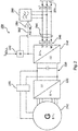
- FIG. 2 shows, in simplified form, an electrical harness 200 in FIG Fig. 1 shown, wind turbine according to the invention.
- the electrical train 200 has a 6-phase ring generator 210, which is set in rotary motion by the wind via a mechanical drive train of the wind energy installation in order to generate a 6-phase alternating current.
- the 6-phase electrical alternating current is transferred from the generator 210 to the rectifier 220, which is connected to the 3-phase inverter 240 via a DC voltage intermediate circuit 230.
- the 6-phase ring generator 210 which is designed as a synchronous generator, is electrically excited by the excitation 250 from the DC voltage intermediate circuit 230.
- the electrical phase 200 thus has a full converter concept in which the 3-phase inverter 240 is used to feed into the network 270.
- This network 270 is usually a wind farm network which feeds into an electrical supply network via a wind farm transformer. Feeding directly into the electrical supply network instead of the parking network 270 is also possible.
- a transformer can also be provided for feeding into the network 270.
- the inverter 240 In order to generate the three-phase current I 1 , I 2 , I 3 for each of the phases U, V, W, the inverter 240 is controlled with a tolerance band method. The control takes place via the controller 242 which, by means of a current detection 244, detects each of the three currents I1, I2, I3 provided or generated by the inverter 240 at the inverter output 246.
- the controller is thus set up to control each phase of the inverter individually by means of the current detection 244.
- the controller 242 can use a current setpoint value Preset Isoll as a function of which the currents I 1 , I 2 , I 3 are controlled.
- the current setpoint Isoll is preferably calculated and specified individually for each phase U, V, W in the system.
- the currents I 1 , I 2 , I 3 generated in this way are also referred to as inverter currents or inverter currents.
- the inverter 240 is further coupled at its inverter output 246 to an active filter 260 in order to filter the inverter current I 1 , I 2 , I 3 provided at the inverter output 241 and thereby a filtered alternating current I * 1 , I * 2 , I * 3 to be provided for feeding into the electrical supply network.
- the active filter 260 is controlled as a function of the detected switching operations of the switches of the inverter 240.
- the fact that the active filter 260 is controlled as a function of these switching operations is indicated by the signal line 262, which transfers the control signals from the controller 242 to the switches of the inverter 240 to the active filter 260 as well.
- a collective evaluation device 264 is provided, which is set up to record the control signals by means of the signal line 262 and other signals AS, such as the intermediate circuit voltage U DC and the current setpoint I soll , and to evaluate them.
- the collective evaluation device 264 then controls the active filter 260 as a function of the control signals detected and evaluated in this way and further signals AS.
- the active filter 260 has a low-pass behavior, the active filter 260 being controlled by means of the control signals for the switches of the inverter 240.
- Fig. 3 shows schematically the structure 300 of an inverter for providing an inverter current by means of a tolerance band method.
- Fig. 3 a part of the in Fig. 2 shown electrical strand.
- the structure 300 has a DC voltage intermediate circuit 330, which is connected to the generator of a wind energy installation via a rectifier.
- the DC voltage intermediate circuit 330 has a first potential U DC + and a second potential Udc- with a center tap M.
- a capacitor with the capacitance C 1 , C 2 is arranged between the center tap M and the two potentials U DC + , U DC , to store energy in the DC voltage intermediate circuit 330 and to smooth the DC voltage 2U DC accordingly.
- the inverter 340 which is connected to the DC voltage intermediate circuit 330, generates a separate current I 1 , I 2 , I 3 at the output 346 of the inverter 340 for each of the three phases U, V, W.
- the inverter 340 has this for each of the three phases U, V, W each have an upper switch T 1 , T 3 , T 5 and a lower switch T 2 , T 4 , T 6 , the upper and lower switches T 1 , T 2 , T 3 , T 4 , T 5 , T 6 can be controlled in particular via the controller 342 by means of a tolerance band method.
- the controller 342 itself operates with a current-controlled tolerance band method.
- the controller 342 records the currents I 1 , I 2 , I 3 generated or provided by the inverter 340 at the output 346 of the inverter 340 by means of a current recorder 344.
- the currents I 1 , I 2 , I 3 recorded in this way are compared with a target value.
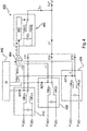
- Fig. 4 shows schematically the coupling 400 of the active filter 460 with the switches OB 11 , UB 11 , OB 21 , UB 21 , OB 31 , UB 31 of several inverter modules 410, 420, 430, whose inverter module currents I 11 , I 12 , I 13 correspond to the Superimpose inverter current I 1 on phase U.
- Fig. 4 thus shows a single-phase view of phase U of a three-phase system, comprising phases U, V and W.
- the inverter modules 410, 420, 430 are each connected on the DC side to a DC voltage intermediate circuit, which is indicated by the terminal voltage U DC + , U DC- .
- the individual inverter modules 410, 420, 430 are activated by means of the activation signals A 11 , A 21 , A 31 .
- the control signals A 11 , A 21 , A 31 give the upper switch OB 11 , OB 21 , OB 31 and the lower switches UB 11 , UB 21 , UB 31 a corresponding switching state.
- the inverter module 410 has the switching state +1, ie that the upper switch OB 11 is active and the lower switch UB 11 is inactive.
- the inverter module 420 has the switching state -1, that is, the upper switch OB 21 is inactive and the lower switch UB 21 is active.
- the inverter module 430 has the switching state -1, that is, the upper switch OB 31 is inactive and the lower switch UB 31 is active.
- control signals A 11 , A 21 , A 31 as well as the intermediate circuit voltage U DC and the current setpoint I soll for the inverter modules 410, 420 430 are fed to the collective evaluation device 464, which transfers them to the control unit 468 of the active filter 460.
- the control signals A 11 , A 21 , A 31 are transferred to the collective evaluation device 464 as switching states, namely in the current state shown as an example as the three switching states +1, -1 and -1.
- the collective evaluation 464 is preferably set up to reproduce both the individual switching states of the individual inverter modules 410, 420, 430 and a total switching state ⁇ of all inverters 410, 420, 430.
- the sum switching state is ⁇ -1.
- the controller 468 of the active filter can then determine the rise of the corresponding edges of the tolerance band method of the inverter modules 410, 420, 430 and accordingly control the switches of the active filter using the control signal S F so that the filtered alternating current I C has fewer harmonics than the inverter current I 1 .
- control unit 468 controls the switches IG 11 , IG 12 of the active filter 460 as a function of the three switching states +1, -1 and -1 as well as the intermediate circuit voltage U DC and the current setpoint Isoll using the control signal SF, which also has a switching state +1 for the switches IG 11 , IG 12 of the active filter 460 presets.
- the active filter 460 uses a DC voltage source C F to generate a filter current I F , which is superimposed with an inverter current I 1 to form a filtered alternating current I * 1 .
- the switches IG 11 , IG 12 of the active filter 460 can be controlled, for example, by means of a look-up table in which the switching states of the switches IG 11 , IG 12 of the active filter 460 are dependent on the switching states of the upper and lower switches OB 11 , OB 21 , OB 31 , UB 11 , UB 21 , UB 31 of the inverter modules 410, 420, 430 are stored.
- the look-up table can either be stored in the collective evaluation device 464 or in the controller 468 of the active filter 460. Such a look-up table that is also referred to as a control table, is below in the Figure 5 shown as an example.
- Fig. 5 shows schematically a control table 500 of a collective evaluation device according to the invention.
- Fig. 5 thereby a control table of an in Fig. 4 shown collective evaluation device.
- control signals A 11 , A 21 , A 31 of the upper and lower switches, the sum switching state ⁇ and the control signal S F of the active filter are plotted.
- the individual columns 520, 530, 540, 560 also have the corresponding switching states of the control signals A 11 , A 21 , A 31 , S F.
- Column 550 shows the corresponding sum switching state ⁇ .
- Line 570 shows the Figure 4 accordingly that the control signals A 11 , A 21 , A 31 , which include the switching states +1, -1 and -1, result in the switching state +1 being transmitted to the switches of the active filter.
Landscapes
- Engineering & Computer Science (AREA)
- Power Engineering (AREA)
- Life Sciences & Earth Sciences (AREA)
- Sustainable Development (AREA)
- Sustainable Energy (AREA)
- Chemical & Material Sciences (AREA)
- Combustion & Propulsion (AREA)
- Mechanical Engineering (AREA)
- General Engineering & Computer Science (AREA)
- Inverter Devices (AREA)
- Supply And Distribution Of Alternating Current (AREA)
Claims (18)
- Procédé d'injection d'un courant alternatif électrique (I*1, I*2, I*3) dans un réseau d'alimentation électrique au moyen d'une éolienne (100), et- l'éolienne (100) comporte au moins un onduleur (340) avec une sortie d'onduleur pour la fourniture d'un courant d'onduleur (I1, I2, I3) électrique et- l'au moins un onduleur (340) est couplé au niveau de sa sortie d'onduleur à un filtre actif (460) afin de filtrer le courant d'onduleur (I1, I2, I3) fourni au niveau de la sortie d'onduleur et de fournir ainsi un courant alternatif (I*1, I*2, I*3) filtré pour l'injection dans le réseau d'alimentation électrique,comprenant les étapes :- de fourniture du courant d'onduleur (I1, I2, I3) électrique au niveau de la sortie d'onduleur par des opérations de commutation au moins d'un commutateur de l'onduleur (340),
caractérisé par- la détection des opérations de commutation de l'onduleur (340) par détection de signaux de commande,- la commande du filtre actif (460) en fonction des opérations de commutation détectées afin de filtrer le courant d'onduleur (I1, I2, I3) fourni au niveau de la sortie d'onduleur et de créer ainsi le courant alternatif (I*1, I*2, I*3) filtré. - Procédé d'injection d'un courant alternatif (I*1, I*2, I*3) électrique selon la revendication 1, caractérisé en ce que- la commande du filtre actif (460) est effectuée de sorte que le courant alternatif (I*1, I*2, I*3) électrique injecté dans le réseau d'alimentation électrique présente une part d'oscillation supérieure réduite par rapport au courant d'onduleur (I1, I2, I3) électrique.
- Procédé d'injection d'un courant alternatif (I*1, I*2, I*3) électrique selon la revendication 1 ou 2,
caractérisé en ce que- les opérations de commutation de l'au moins un commutateur présentent une fréquence de commutation et- la détection des opérations de commutation est effectuée avec une fréquence de balayage, dans lequel- la fréquence de balayage est au moins deux fois plus grande, en particulier au moins cinq fois plus grande, de préférence au moins dix fois plus grande, que la fréquence de commutation de l'opération de commutation à détecter du commutateur. - Procédé d'injection d'un courant alternatif (I*1, I*2, I*3) électrique selon l'une des revendications précédentes,
caractérisé en ce que- la commande du filtre actif (460) est effectuée en fonction d'un signal de commande déclenchant les opérations de commutation de l'au moins un commutateur, et en outre ou en variante- la commande du filtre actif (460) est effectuée en fonction d'une tension de commande déclenchant les opérations de commutation de l'au moins un commutateur. - Procédé d'injection d'un courant alternatif (I*1, I*2, I*3) électrique selon l'une des revendications précédentes,
caractérisé en ce que- l'au moins un onduleur (340) est commandé au moyen d'un procédé de bande de tolérance afin de fournir le courant d'onduleur (I1, I2, I3) au niveau de la sortie d'onduleur et le filtre actif filtre le courant d'onduleur (I1, I2, I3) en fonction des opérations de commutation générées par le procédé de bande de tolérance de l'au moins un commutateur. - Procédé d'injection d'un courant alternatif (I*1, I*2, I*3) électrique selon l'une des revendications précédentes,
caractérisé en ce que- la commande du filtre actif (460) est effectuée sans tenir compte du courant d'onduleur (I1, I2, I3) fourni. - Procédé d'injection d'un courant alternatif (I*1, I*2, I*3) électrique selon l'une des revendications précédentes,
caractérisé en ce que- la commande du filtre actif (460) est effectuée en fonction des opérations de commutation détectées afin de réduire au moins une part d'oscillation supérieure du courant d'onduleur (I1, I2, I3), en particulier de minimiser une part d'oscillation supérieure de courant du courant d'onduleur (I1, I2, I3), de préférence de réduire une part d'oscillation supérieure de courant qui est sélectionnée à partir de la liste comprenant :- une 1re oscillation supérieure de courant harmonique à- une 60e oscillation supérieure de courant harmonique. - Procédé d'injection d'un courant alternatif (I*1, I*2, I*3) électrique selon l'une des revendications précédentes,
caractérisé en ce que- l'onduleur (340) électrique comporte plusieurs modules d'onduleur avec une sortie de module d'onduleur pour la fourniture d'un courant de module d'onduleur et les sorties de module d'onduleur sont connectées entre elles de sorte que leurs courants de module d'onduleur se superposent pour former un courant d'onduleur, dans lequel- un dispositif d'évaluation de collecte est prévu pour la détection et l'évaluation de signaux de commande des modules d'onduleur, et le dispositif d'évaluation de collecte commande le filtre actif (460) pour la filtration du courant d'onduleur (I1, I2, I3). - Procédé d'injection d'un courant alternatif (I*1, I*2, I*3) électrique selon l'une des revendications précédentes,
caractérisé en ce que- le filtre actif (460) est commandé en outre en fonction d'au moins une tension de circuit intermédiaire (DDC) de l'au moins un onduleur (340) et/ou d'une valeur de consigne de courant pour l'au moins un onduleur (340). - Éolienne (100) comprenant au moins un onduleur (340) avec une sortie d'onduleur pour la fourniture d'un premier courant alternatif (I1, I2, I3) et un filtre actif (460) couplé au niveau de la sortie d'onduleur pour la filtration du courant d'onduleur (I1, I2, I3) afin de créer un courant alternatif (I*1, I*2, I*3) filtré pour l'injection dans le réseau d'alimentation électrique,
caractérisée en ce que- le filtre actif (460) est aménagé afin d'être commandé en fonction d'une opération de commutation détectée par détection de signaux de commande au moins d'un commutateur de l'onduleur (340) afin de filtrer le courant d'onduleur (I1, I2, I3) et de créer ainsi le courant alternatif (I*1, I*2, I*3) filtré. - Éolienne (100) selon la revendication 10,
caractérisée en ce que
l'éolienne (100) présente un dispositif de commande pour la commande de l'onduleur (340) afin de réaliser un procédé selon l'une des revendications 1 à 9. - Éolienne (100) selon la revendication 10 ou 11,
caractérisée en ce que- l'au moins un onduleur (340) présente au moins six commutateurs, dans laquelle respectivement deux commutateurs, en particulier un commutateur supérieur et un commutateur inférieur, sont réalisés,
afin de fournir un courant pour respectivement une phase du courant d'onduleur. - Éolienne (100) selon l'une des revendications 10 à 12,
caractérisée en ce que- l'au moins un commutateur de l'onduleur (340) ou les commutateurs de l'onduleur (340) sont réalisés en tant que IGBT ou MOSFET. - Éolienne (100) selon l'une des revendications 10 à 13,
caractérisée en ce que- l'au moins un onduleur (340) est réalisé afin d'être commandé au moyen d'un procédé de bande de tolérance et le filtre actif (460) est réalisé afin de filtrer le courant d'onduleur (I1, I2, I3) en fonction des opérations de commutation générées par le procédé de bande de tolérance de l'au moins un commutateur. - Éolienne (100) selon l'une des revendications 10 à 14,
caractérisée en ce que- l'onduleur (340) est un onduleur de puissance, en particulier un onduleur de puissance qui est aménagé afin d'être utilisé dans un concept d'onduleur complet d'une éolienne (100). - Éolienne (100) selon l'une des revendications 10 à 15,
caractérisée en ce que- le filtre actif (460) présente au moins un composant actif, en particulier au moins un IGBT ou un MOSFET, de préférence au moins un IGBT de carbure de silicium ou un MOSFET de carbure de silicium qui est conçu afin de travailler avec une fréquence de balayage qui est de préférence supérieure à la fréquence de commutation de l'au moins un commutateur ou qui est supérieure à la fréquence de commutation des commutateurs multipliée par le nombre des modules d'onduleur de l'onduleur. - Éolienne (100) selon l'une des revendications 10 à 16,
caractérisée en ce que- l'onduleur (340) électrique comporte plusieurs modules d'onduleur avec une sortie de module d'onduleur pour la sortie d'un courant de module d'onduleur et les sorties de module d'onduleur sont connectées entre elles de sorte que leurs courants de module d'onduleur se superposent pour former un courant d'onduleur, dans laquelle- un dispositif d'évaluation de collecte est prévu pour la détection et l'évaluation de signaux de commande des modules d'onduleur, et le dispositif d'évaluation de collecte (264) est réalisé afin de commander le filtre actif (460) pour la filtration du courant d'onduleur (I1, I2, I3). - Éolienne (100) selon l'une des revendications 10 à 17,
caractérisée en ce que- le filtre actif (460) est interconnecté parallèlement à la sortie d'onduleur de sorte que le filtre actif (460) soit conçu afin de filtrer, en particulier de réduire, au moins une oscillation supérieure de courant du premier courant alternatif.
Applications Claiming Priority (2)
| Application Number | Priority Date | Filing Date | Title |
|---|---|---|---|
| DE102017101359.8A DE102017101359A1 (de) | 2017-01-25 | 2017-01-25 | Verfahren zum Einspeisen eines elektrischen Wechselstromes |
| PCT/EP2018/051777 WO2018138184A1 (fr) | 2017-01-25 | 2018-01-25 | Procédé pour l'injection d'un courant électrique alternatif |
Publications (2)
| Publication Number | Publication Date |
|---|---|
| EP3574561A1 EP3574561A1 (fr) | 2019-12-04 |
| EP3574561B1 true EP3574561B1 (fr) | 2020-11-18 |
Family
ID=61094477
Family Applications (1)
| Application Number | Title | Priority Date | Filing Date |
|---|---|---|---|
| EP18702193.6A Active EP3574561B1 (fr) | 2017-01-25 | 2018-01-25 | Procédé pour l'injection d'un courant électrique alternatif |
Country Status (11)
| Country | Link |
|---|---|
| US (1) | US11159083B2 (fr) |
| EP (1) | EP3574561B1 (fr) |
| JP (1) | JP2020505895A (fr) |
| KR (1) | KR20190107124A (fr) |
| CN (1) | CN110249495B (fr) |
| BR (1) | BR112019015185B1 (fr) |
| CA (1) | CA3049178C (fr) |
| DE (1) | DE102017101359A1 (fr) |
| DK (1) | DK3574561T3 (fr) |
| RU (1) | RU2721171C1 (fr) |
| WO (1) | WO2018138184A1 (fr) |
Families Citing this family (4)
| Publication number | Priority date | Publication date | Assignee | Title |
|---|---|---|---|---|
| DE102017113006A1 (de) * | 2017-06-13 | 2018-12-13 | Wobben Properties Gmbh | Verfahren zum Einspeisen elektrischer Leistung in ein elektrisches Versorgungsnetz mittels einer umrichtergeführten Einspeisevorrichtung |
| EP3930173A1 (fr) * | 2020-06-26 | 2021-12-29 | Wobben Properties GmbH | Procédé de commande d'un onduleur |
| EP3996270A1 (fr) * | 2020-11-10 | 2022-05-11 | Wobben Properties GmbH | Méthode de commande destinée à un convertisseur de puissance |
| EP4404449A1 (fr) * | 2023-01-23 | 2024-07-24 | Siemens Aktiengesellschaft | Procédé de fonctionnement d'un dispositif onduleur, produit programme d'ordinateur, support d'informations lisible par ordinateur et dispositif onduleur |
Citations (1)
| Publication number | Priority date | Publication date | Assignee | Title |
|---|---|---|---|---|
| DE102008018497A1 (de) * | 2008-04-11 | 2009-10-22 | Siemens Aktiengesellschaft | Wechselrichter, insbesondere Solarwechselrichter, mit einem aktven Netzfilter |
Family Cites Families (17)
| Publication number | Priority date | Publication date | Assignee | Title |
|---|---|---|---|---|
| JP2863833B2 (ja) * | 1996-09-18 | 1999-03-03 | 岡山大学長 | アクティブコモンモードキャンセラ |
| JP2001031165A (ja) | 1999-07-26 | 2001-02-06 | Asahi Chem Ind Co Ltd | ガラス板搬送箱 |
| JP2001231165A (ja) * | 2000-02-17 | 2001-08-24 | Chiyoda:Kk | 電流形能動フィルタ回路 |
| JP2003209973A (ja) * | 2002-01-11 | 2003-07-25 | Meidensha Corp | 電力変換装置 |
| RU2286639C1 (ru) * | 2005-05-05 | 2006-10-27 | Открытое акционерное общество "Государственное машиностроительное конструкторское бюро "Радуга" им. А.Я. Березняка" | Способ бесперебойного электроснабжения потребителей электроэнергетической системы, работающей на нестабильных источниках энергии |
| WO2010079235A2 (fr) * | 2009-01-12 | 2010-07-15 | Vestas Wind Systems A/S | Fréquence de commutation d'un convertisseur fonction de la charge |
| WO2012042706A1 (fr) * | 2010-09-29 | 2012-04-05 | パナソニック株式会社 | Appareil convertisseur de puissance |
| US8279649B2 (en) * | 2010-10-11 | 2012-10-02 | Solarbridge Technologies, Inc. | Apparatus and method for controlling a power inverter |
| JP5333485B2 (ja) * | 2011-03-04 | 2013-11-06 | 株式会社デンソー | 電力変換装置 |
| WO2013001820A1 (fr) | 2011-06-28 | 2013-01-03 | 京セラ株式会社 | Dispositif d'onduleur de connexion de système et son procédé de commande |
| US20140203559A1 (en) | 2013-01-18 | 2014-07-24 | General Electric Company | Connection for improved current balancing between parallel bridge circuits |
| US9099936B2 (en) * | 2013-03-14 | 2015-08-04 | General Electric Company | High voltage direct current (HVDC) converter system and method of operating the same |
| CN104009497B (zh) * | 2014-06-16 | 2016-08-24 | 东南大学 | 一种风电机组低电压穿越和有源滤波补偿装置及切换方法 |
| DE102014219052A1 (de) * | 2014-09-22 | 2016-03-24 | Wobben Properties Gmbh | Verfahren zum Erzeugen eines elektrischen Wechselstroms |
| US9960712B2 (en) * | 2015-03-25 | 2018-05-01 | Sunpower Corporation | Converter topologies and control |
| US10756546B2 (en) * | 2017-08-10 | 2020-08-25 | Bloom Energy Corporation | Methods of advanced grid and microgrid support functionalities through hybrid fuel cell systems |
| DE102018103996A1 (de) * | 2018-02-22 | 2019-08-22 | Innogy Se | Reduzierung von Oberwellen in Stromnetzen |
-
2017
- 2017-01-25 DE DE102017101359.8A patent/DE102017101359A1/de not_active Withdrawn
-
2018
- 2018-01-25 EP EP18702193.6A patent/EP3574561B1/fr active Active
- 2018-01-25 KR KR1020197024868A patent/KR20190107124A/ko not_active Ceased
- 2018-01-25 JP JP2019537360A patent/JP2020505895A/ja active Pending
- 2018-01-25 DK DK18702193.6T patent/DK3574561T3/da active
- 2018-01-25 WO PCT/EP2018/051777 patent/WO2018138184A1/fr not_active Ceased
- 2018-01-25 CN CN201880008083.5A patent/CN110249495B/zh active Active
- 2018-01-25 CA CA3049178A patent/CA3049178C/fr active Active
- 2018-01-25 RU RU2019126460A patent/RU2721171C1/ru active
- 2018-01-25 BR BR112019015185-0A patent/BR112019015185B1/pt active IP Right Grant
-
2019
- 2019-07-22 US US16/518,747 patent/US11159083B2/en active Active
Patent Citations (1)
| Publication number | Priority date | Publication date | Assignee | Title |
|---|---|---|---|---|
| DE102008018497A1 (de) * | 2008-04-11 | 2009-10-22 | Siemens Aktiengesellschaft | Wechselrichter, insbesondere Solarwechselrichter, mit einem aktven Netzfilter |
Also Published As
| Publication number | Publication date |
|---|---|
| US11159083B2 (en) | 2021-10-26 |
| DE102017101359A1 (de) | 2018-07-26 |
| EP3574561A1 (fr) | 2019-12-04 |
| US20190348902A1 (en) | 2019-11-14 |
| KR20190107124A (ko) | 2019-09-18 |
| WO2018138184A1 (fr) | 2018-08-02 |
| CN110249495B (zh) | 2024-05-14 |
| BR112019015185B1 (pt) | 2023-10-10 |
| CN110249495A (zh) | 2019-09-17 |
| DK3574561T3 (da) | 2020-12-07 |
| CA3049178C (fr) | 2021-11-23 |
| JP2020505895A (ja) | 2020-02-20 |
| CA3049178A1 (fr) | 2018-08-02 |
| RU2721171C1 (ru) | 2020-05-18 |
| BR112019015185A2 (pt) | 2020-03-24 |
Similar Documents
| Publication | Publication Date | Title |
|---|---|---|
| EP2730019B1 (fr) | Procédé pour faire fonctionner un onduleur et onduleur tolérant aux pannes de secteur | |
| EP3574561B1 (fr) | Procédé pour l'injection d'un courant électrique alternatif | |
| WO2014033073A1 (fr) | Parc éolien à réseau de tension continue | |
| WO2005004317A2 (fr) | Convertisseur de frequences destine a des generateurs grande vitesse | |
| AT520392A1 (de) | Energiespeicheremulator und Verfahren zur Emulation eines Energiespeichers | |
| DE102011000459B4 (de) | Verfahren zur Lieferung von Blindstrom mit einem Umrichter sowie Umrichteranordnung und Energieversorgungsanlage | |
| DE19651364A1 (de) | Vorrichtung zur Verbesserung der Netzverträglichkeit von Windkraftanlagen mit Asynchrongeneratoren | |
| DE19509658C2 (de) | Schaltungsanordnung zur Erzeugung eines Netzausfallsignals bei einem Antriebsregelgerät | |
| EP3449554B1 (fr) | Onduleur et procédé pour générer un courant alternatif | |
| EP3117511A1 (fr) | Procédé d'identification de l'effondrement d'une tension | |
| DE202006001063U1 (de) | Wechselrichter zur Einspeisung elektrischer, mit einer PV-Anlage o.dgl. erzeugter Energie in ein Energieversorgungsnetz | |
| EP3516763B1 (fr) | Procédé de production d'un courant alternatif au moyen d'un convertisseur d'une éolienne | |
| EP1137149A2 (fr) | Appareil et procédé pour l'alimentation d'energie d'un réseau autonome | |
| EP2182626A1 (fr) | Procédé destiné au fonctionnement d'un convertisseur de courant et convertisseur de courant fonctionnant selon ce procédé | |
| EP2713494A1 (fr) | Dispositif d'alimentation en énergie pour l'alimentation de l'énergie électrique générée par l'énergie cinétique dans un réseau de distribution de courant triphasé | |
| DE29621449U1 (de) | Vorrichtung zur Verbesserung der Netzverträglichkeit von Windkraftanlagen mit Asynchrongerneratoren | |
| EP3046204A1 (fr) | Éolienne | |
| EP3984124A1 (fr) | Convertisseur à double usage | |
| AT402133B (de) | Steuereinrichtung für die energieversorgung eines verbraucherkreises eines gleichstromverbrauchers und ein verfahren zum betrieb einer derartigen steuereinrichtung | |
| WO2014008976A2 (fr) | Dispositif de charge pour une batterie haute tension de véhicule à moteur et véhicule à moteur | |
| EP3008787B1 (fr) | Système de charge et procédé d'un accumulateur, poursuite du point de puissance maximale pour charger un accumulateur | |
| DE2638547A1 (de) | Verfahren zum notbetrieb eines eine drehfeldmaschine speisenden umrichters und vorrichtung zur durchfuehrung des verfahrens | |
| DE102009008073A1 (de) | Verfahren zum Betrieb eines Stromrichters und nach dem Verfahren arbeitender Stromrichter | |
| EP3993253A1 (fr) | Réglage hysterese d'un courant avec temps morts pour éviter des commutations fausses sous la dependence d'oscillations dans un convertisseur | |
| DE202012100041U1 (de) | Windkraftanlage |
Legal Events
| Date | Code | Title | Description |
|---|---|---|---|
| STAA | Information on the status of an ep patent application or granted ep patent |
Free format text: STATUS: UNKNOWN |
|
| STAA | Information on the status of an ep patent application or granted ep patent |
Free format text: STATUS: THE INTERNATIONAL PUBLICATION HAS BEEN MADE |
|
| PUAI | Public reference made under article 153(3) epc to a published international application that has entered the european phase |
Free format text: ORIGINAL CODE: 0009012 |
|
| STAA | Information on the status of an ep patent application or granted ep patent |
Free format text: STATUS: REQUEST FOR EXAMINATION WAS MADE |
|
| 17P | Request for examination filed |
Effective date: 20190826 |
|
| AK | Designated contracting states |
Kind code of ref document: A1 Designated state(s): AL AT BE BG CH CY CZ DE DK EE ES FI FR GB GR HR HU IE IS IT LI LT LU LV MC MK MT NL NO PL PT RO RS SE SI SK SM TR |
|
| AX | Request for extension of the european patent |
Extension state: BA ME |
|
| DAV | Request for validation of the european patent (deleted) | ||
| DAX | Request for extension of the european patent (deleted) | ||
| GRAP | Despatch of communication of intention to grant a patent |
Free format text: ORIGINAL CODE: EPIDOSNIGR1 |
|
| STAA | Information on the status of an ep patent application or granted ep patent |
Free format text: STATUS: GRANT OF PATENT IS INTENDED |
|
| INTG | Intention to grant announced |
Effective date: 20200805 |
|
| GRAS | Grant fee paid |
Free format text: ORIGINAL CODE: EPIDOSNIGR3 |
|
| GRAA | (expected) grant |
Free format text: ORIGINAL CODE: 0009210 |
|
| STAA | Information on the status of an ep patent application or granted ep patent |
Free format text: STATUS: THE PATENT HAS BEEN GRANTED |
|
| RIN1 | Information on inventor provided before grant (corrected) |
Inventor name: HEYEN, CHRISTIAN |
|
| AK | Designated contracting states |
Kind code of ref document: B1 Designated state(s): AL AT BE BG CH CY CZ DE DK EE ES FI FR GB GR HR HU IE IS IT LI LT LU LV MC MK MT NL NO PL PT RO RS SE SI SK SM TR |
|
| REG | Reference to a national code |
Ref country code: GB Ref legal event code: FG4D Free format text: NOT ENGLISH |
|
| REG | Reference to a national code |
Ref country code: CH Ref legal event code: EP |
|
| REG | Reference to a national code |
Ref country code: DK Ref legal event code: T3 Effective date: 20201203 |
|
| REG | Reference to a national code |
Ref country code: IE Ref legal event code: FG4D Free format text: LANGUAGE OF EP DOCUMENT: GERMAN |
|
| REG | Reference to a national code |
Ref country code: DE Ref legal event code: R096 Ref document number: 502018003052 Country of ref document: DE |
|
| REG | Reference to a national code |
Ref country code: AT Ref legal event code: REF Ref document number: 1336813 Country of ref document: AT Kind code of ref document: T Effective date: 20201215 |
|
| REG | Reference to a national code |
Ref country code: NL Ref legal event code: FP |
|
| PG25 | Lapsed in a contracting state [announced via postgrant information from national office to epo] |
Ref country code: GR Free format text: LAPSE BECAUSE OF FAILURE TO SUBMIT A TRANSLATION OF THE DESCRIPTION OR TO PAY THE FEE WITHIN THE PRESCRIBED TIME-LIMIT Effective date: 20210219 Ref country code: NO Free format text: LAPSE BECAUSE OF FAILURE TO SUBMIT A TRANSLATION OF THE DESCRIPTION OR TO PAY THE FEE WITHIN THE PRESCRIBED TIME-LIMIT Effective date: 20210218 Ref country code: PT Free format text: LAPSE BECAUSE OF FAILURE TO SUBMIT A TRANSLATION OF THE DESCRIPTION OR TO PAY THE FEE WITHIN THE PRESCRIBED TIME-LIMIT Effective date: 20210318 Ref country code: RS Free format text: LAPSE BECAUSE OF FAILURE TO SUBMIT A TRANSLATION OF THE DESCRIPTION OR TO PAY THE FEE WITHIN THE PRESCRIBED TIME-LIMIT Effective date: 20201118 Ref country code: FI Free format text: LAPSE BECAUSE OF FAILURE TO SUBMIT A TRANSLATION OF THE DESCRIPTION OR TO PAY THE FEE WITHIN THE PRESCRIBED TIME-LIMIT Effective date: 20201118 |
|
| PG25 | Lapsed in a contracting state [announced via postgrant information from national office to epo] |
Ref country code: BG Free format text: LAPSE BECAUSE OF FAILURE TO SUBMIT A TRANSLATION OF THE DESCRIPTION OR TO PAY THE FEE WITHIN THE PRESCRIBED TIME-LIMIT Effective date: 20210218 Ref country code: SE Free format text: LAPSE BECAUSE OF FAILURE TO SUBMIT A TRANSLATION OF THE DESCRIPTION OR TO PAY THE FEE WITHIN THE PRESCRIBED TIME-LIMIT Effective date: 20201118 Ref country code: LV Free format text: LAPSE BECAUSE OF FAILURE TO SUBMIT A TRANSLATION OF THE DESCRIPTION OR TO PAY THE FEE WITHIN THE PRESCRIBED TIME-LIMIT Effective date: 20201118 Ref country code: PL Free format text: LAPSE BECAUSE OF FAILURE TO SUBMIT A TRANSLATION OF THE DESCRIPTION OR TO PAY THE FEE WITHIN THE PRESCRIBED TIME-LIMIT Effective date: 20201118 Ref country code: IS Free format text: LAPSE BECAUSE OF FAILURE TO SUBMIT A TRANSLATION OF THE DESCRIPTION OR TO PAY THE FEE WITHIN THE PRESCRIBED TIME-LIMIT Effective date: 20210318 |
|
| REG | Reference to a national code |
Ref country code: LT Ref legal event code: MG9D |
|
| PG25 | Lapsed in a contracting state [announced via postgrant information from national office to epo] |
Ref country code: HR Free format text: LAPSE BECAUSE OF FAILURE TO SUBMIT A TRANSLATION OF THE DESCRIPTION OR TO PAY THE FEE WITHIN THE PRESCRIBED TIME-LIMIT Effective date: 20201118 |
|
| PG25 | Lapsed in a contracting state [announced via postgrant information from national office to epo] |
Ref country code: SK Free format text: LAPSE BECAUSE OF FAILURE TO SUBMIT A TRANSLATION OF THE DESCRIPTION OR TO PAY THE FEE WITHIN THE PRESCRIBED TIME-LIMIT Effective date: 20201118 Ref country code: SM Free format text: LAPSE BECAUSE OF FAILURE TO SUBMIT A TRANSLATION OF THE DESCRIPTION OR TO PAY THE FEE WITHIN THE PRESCRIBED TIME-LIMIT Effective date: 20201118 Ref country code: CZ Free format text: LAPSE BECAUSE OF FAILURE TO SUBMIT A TRANSLATION OF THE DESCRIPTION OR TO PAY THE FEE WITHIN THE PRESCRIBED TIME-LIMIT Effective date: 20201118 Ref country code: EE Free format text: LAPSE BECAUSE OF FAILURE TO SUBMIT A TRANSLATION OF THE DESCRIPTION OR TO PAY THE FEE WITHIN THE PRESCRIBED TIME-LIMIT Effective date: 20201118 Ref country code: RO Free format text: LAPSE BECAUSE OF FAILURE TO SUBMIT A TRANSLATION OF THE DESCRIPTION OR TO PAY THE FEE WITHIN THE PRESCRIBED TIME-LIMIT Effective date: 20201118 Ref country code: LT Free format text: LAPSE BECAUSE OF FAILURE TO SUBMIT A TRANSLATION OF THE DESCRIPTION OR TO PAY THE FEE WITHIN THE PRESCRIBED TIME-LIMIT Effective date: 20201118 |
|
| REG | Reference to a national code |
Ref country code: DE Ref legal event code: R097 Ref document number: 502018003052 Country of ref document: DE |
|
| PG25 | Lapsed in a contracting state [announced via postgrant information from national office to epo] |
Ref country code: MC Free format text: LAPSE BECAUSE OF FAILURE TO SUBMIT A TRANSLATION OF THE DESCRIPTION OR TO PAY THE FEE WITHIN THE PRESCRIBED TIME-LIMIT Effective date: 20201118 |
|
| REG | Reference to a national code |
Ref country code: CH Ref legal event code: PL |
|
| PLBE | No opposition filed within time limit |
Free format text: ORIGINAL CODE: 0009261 |
|
| STAA | Information on the status of an ep patent application or granted ep patent |
Free format text: STATUS: NO OPPOSITION FILED WITHIN TIME LIMIT |
|
| PG25 | Lapsed in a contracting state [announced via postgrant information from national office to epo] |
Ref country code: LU Free format text: LAPSE BECAUSE OF NON-PAYMENT OF DUE FEES Effective date: 20210125 |
|
| REG | Reference to a national code |
Ref country code: BE Ref legal event code: MM Effective date: 20210131 |
|
| 26N | No opposition filed |
Effective date: 20210819 |
|
| PG25 | Lapsed in a contracting state [announced via postgrant information from national office to epo] |
Ref country code: AL Free format text: LAPSE BECAUSE OF FAILURE TO SUBMIT A TRANSLATION OF THE DESCRIPTION OR TO PAY THE FEE WITHIN THE PRESCRIBED TIME-LIMIT Effective date: 20201118 Ref country code: IT Free format text: LAPSE BECAUSE OF FAILURE TO SUBMIT A TRANSLATION OF THE DESCRIPTION OR TO PAY THE FEE WITHIN THE PRESCRIBED TIME-LIMIT Effective date: 20201118 |
|
| PG25 | Lapsed in a contracting state [announced via postgrant information from national office to epo] |
Ref country code: CH Free format text: LAPSE BECAUSE OF NON-PAYMENT OF DUE FEES Effective date: 20210131 Ref country code: SI Free format text: LAPSE BECAUSE OF FAILURE TO SUBMIT A TRANSLATION OF THE DESCRIPTION OR TO PAY THE FEE WITHIN THE PRESCRIBED TIME-LIMIT Effective date: 20201118 Ref country code: LI Free format text: LAPSE BECAUSE OF NON-PAYMENT OF DUE FEES Effective date: 20210131 |
|
| PG25 | Lapsed in a contracting state [announced via postgrant information from national office to epo] |
Ref country code: IE Free format text: LAPSE BECAUSE OF NON-PAYMENT OF DUE FEES Effective date: 20210125 Ref country code: ES Free format text: LAPSE BECAUSE OF FAILURE TO SUBMIT A TRANSLATION OF THE DESCRIPTION OR TO PAY THE FEE WITHIN THE PRESCRIBED TIME-LIMIT Effective date: 20201118 |
|
| PG25 | Lapsed in a contracting state [announced via postgrant information from national office to epo] |
Ref country code: IS Free format text: LAPSE BECAUSE OF FAILURE TO SUBMIT A TRANSLATION OF THE DESCRIPTION OR TO PAY THE FEE WITHIN THE PRESCRIBED TIME-LIMIT Effective date: 20210318 |
|
| PG25 | Lapsed in a contracting state [announced via postgrant information from national office to epo] |
Ref country code: BE Free format text: LAPSE BECAUSE OF NON-PAYMENT OF DUE FEES Effective date: 20210131 |
|
| PG25 | Lapsed in a contracting state [announced via postgrant information from national office to epo] |
Ref country code: CY Free format text: LAPSE BECAUSE OF FAILURE TO SUBMIT A TRANSLATION OF THE DESCRIPTION OR TO PAY THE FEE WITHIN THE PRESCRIBED TIME-LIMIT Effective date: 20201118 |
|
| PG25 | Lapsed in a contracting state [announced via postgrant information from national office to epo] |
Ref country code: HU Free format text: LAPSE BECAUSE OF FAILURE TO SUBMIT A TRANSLATION OF THE DESCRIPTION OR TO PAY THE FEE WITHIN THE PRESCRIBED TIME-LIMIT; INVALID AB INITIO Effective date: 20180125 |
|
| REG | Reference to a national code |
Ref country code: AT Ref legal event code: MM01 Ref document number: 1336813 Country of ref document: AT Kind code of ref document: T Effective date: 20230125 |
|
| PG25 | Lapsed in a contracting state [announced via postgrant information from national office to epo] |
Ref country code: AT Free format text: LAPSE BECAUSE OF NON-PAYMENT OF DUE FEES Effective date: 20230125 |
|
| PG25 | Lapsed in a contracting state [announced via postgrant information from national office to epo] |
Ref country code: MK Free format text: LAPSE BECAUSE OF FAILURE TO SUBMIT A TRANSLATION OF THE DESCRIPTION OR TO PAY THE FEE WITHIN THE PRESCRIBED TIME-LIMIT Effective date: 20201118 Ref country code: AT Free format text: LAPSE BECAUSE OF NON-PAYMENT OF DUE FEES Effective date: 20230125 |
|
| PG25 | Lapsed in a contracting state [announced via postgrant information from national office to epo] |
Ref country code: MT Free format text: LAPSE BECAUSE OF FAILURE TO SUBMIT A TRANSLATION OF THE DESCRIPTION OR TO PAY THE FEE WITHIN THE PRESCRIBED TIME-LIMIT Effective date: 20201118 |
|
| PGFP | Annual fee paid to national office [announced via postgrant information from national office to epo] |
Ref country code: DK Payment date: 20250122 Year of fee payment: 8 |
|
| PG25 | Lapsed in a contracting state [announced via postgrant information from national office to epo] |
Ref country code: TR Free format text: LAPSE BECAUSE OF FAILURE TO SUBMIT A TRANSLATION OF THE DESCRIPTION OR TO PAY THE FEE WITHIN THE PRESCRIBED TIME-LIMIT Effective date: 20201118 |
|
| PGFP | Annual fee paid to national office [announced via postgrant information from national office to epo] |
Ref country code: NL Payment date: 20260121 Year of fee payment: 9 |
|
| PGFP | Annual fee paid to national office [announced via postgrant information from national office to epo] |
Ref country code: GB Payment date: 20260122 Year of fee payment: 9 |
|
| PGFP | Annual fee paid to national office [announced via postgrant information from national office to epo] |
Ref country code: DE Payment date: 20260204 Year of fee payment: 9 |
|
| PGFP | Annual fee paid to national office [announced via postgrant information from national office to epo] |
Ref country code: AT Payment date: 20260410 Year of fee payment: 5 |
|
| PGFP | Annual fee paid to national office [announced via postgrant information from national office to epo] |
Ref country code: FR Payment date: 20260121 Year of fee payment: 9 |