EP3574880A1 - Bettvorrichtung - Google Patents
Bettvorrichtung Download PDFInfo
- Publication number
- EP3574880A1 EP3574880A1 EP18761982.0A EP18761982A EP3574880A1 EP 3574880 A1 EP3574880 A1 EP 3574880A1 EP 18761982 A EP18761982 A EP 18761982A EP 3574880 A1 EP3574880 A1 EP 3574880A1
- Authority
- EP
- European Patent Office
- Prior art keywords
- floor plate
- frame
- rocking
- floor
- width direction
- Prior art date
- Legal status (The legal status is an assumption and is not a legal conclusion. Google has not performed a legal analysis and makes no representation as to the accuracy of the status listed.)
- Withdrawn
Links
Images


















Classifications
-
- A—HUMAN NECESSITIES
- A61—MEDICAL OR VETERINARY SCIENCE; HYGIENE
- A61G—TRANSPORT, PERSONAL CONVEYANCES, OR ACCOMMODATION SPECIALLY ADAPTED FOR PATIENTS OR DISABLED PERSONS; OPERATING TABLES OR CHAIRS; CHAIRS FOR DENTISTRY; FUNERAL DEVICES
- A61G7/00—Beds specially adapted for nursing; Devices for lifting patients or disabled persons
- A61G7/002—Beds specially adapted for nursing; Devices for lifting patients or disabled persons having adjustable mattress frame
-
- A—HUMAN NECESSITIES
- A61—MEDICAL OR VETERINARY SCIENCE; HYGIENE
- A61G—TRANSPORT, PERSONAL CONVEYANCES, OR ACCOMMODATION SPECIALLY ADAPTED FOR PATIENTS OR DISABLED PERSONS; OPERATING TABLES OR CHAIRS; CHAIRS FOR DENTISTRY; FUNERAL DEVICES
- A61G7/00—Beds specially adapted for nursing; Devices for lifting patients or disabled persons
- A61G7/002—Beds specially adapted for nursing; Devices for lifting patients or disabled persons having adjustable mattress frame
- A61G7/008—Beds specially adapted for nursing; Devices for lifting patients or disabled persons having adjustable mattress frame tiltable around longitudinal axis, e.g. for rolling
-
- A—HUMAN NECESSITIES
- A61—MEDICAL OR VETERINARY SCIENCE; HYGIENE
- A61G—TRANSPORT, PERSONAL CONVEYANCES, OR ACCOMMODATION SPECIALLY ADAPTED FOR PATIENTS OR DISABLED PERSONS; OPERATING TABLES OR CHAIRS; CHAIRS FOR DENTISTRY; FUNERAL DEVICES
- A61G7/00—Beds specially adapted for nursing; Devices for lifting patients or disabled persons
- A61G7/002—Beds specially adapted for nursing; Devices for lifting patients or disabled persons having adjustable mattress frame
- A61G7/015—Beds specially adapted for nursing; Devices for lifting patients or disabled persons having adjustable mattress frame divided into different adjustable sections, e.g. for Gatch position
-
- A—HUMAN NECESSITIES
- A61—MEDICAL OR VETERINARY SCIENCE; HYGIENE
- A61G—TRANSPORT, PERSONAL CONVEYANCES, OR ACCOMMODATION SPECIALLY ADAPTED FOR PATIENTS OR DISABLED PERSONS; OPERATING TABLES OR CHAIRS; CHAIRS FOR DENTISTRY; FUNERAL DEVICES
- A61G7/00—Beds specially adapted for nursing; Devices for lifting patients or disabled persons
- A61G7/05—Parts, details or accessories of beds
- A61G7/057—Arrangements for preventing bed-sores or for supporting patients with burns, e.g. mattresses specially adapted therefor
Definitions
- the present invention relates generally to a bed device configured to be able to perform vertically drive, back-raising drive or lateral rocking drive of a floor plate body on which a user lies on the back.
- a user such as an elderly person or a sick person unable to turn over or raise its own body by itself must stay supine on the mattress of the bed device for a long time. If the user is in a supine position for a long time, bedsores may occur in the back of the body, especially in the buttocks, resulting in increase in pain.
- bed devices disclosed in, for example, Patent Literatures 1 to 4 have been proposed.
- the bed devices disclosed in Patent Literatures 1 to 4 comprise a base frame, and a vertical frame is provided on the base frame so as to be capable of being driven up and down.
- a rocking frame (rotating frame) is supported by the vertical frame so as to be capable of tilting in the width direction.
- the rocking frame is driven to tilt in the width direction with one end or the other end in the width direction serving as a fulcrum, by a rocking drive mechanism provided on the vertical frame.
- a floor plate body is provided on the upper surface of the rocking described in Patent Literature 1.
- the floor plate body has a central floor plate and side floor plates pivotally connected only upward to both sides of the central floor plate.
- the central floor plate is divided into a plurality of floor parts in the longitudinal direction, which are pivotally connected to each other.
- One of the floor parts that is located substantially at the center in the longitudinal direction is attached and fixed to the rocking frame.
- the lower surface of one of the side floor plates positioned on one side in the width direction, that is, the lower side of the inclining direction contacts a contact member provided at an end portion of the vertical frame in the width direction and bends in a direction opposite to the inclining direction of the rocking frame, that is, an upward direction.
- the rocking frame is tilted in the lateral direction, the user such as a patient who lies on the floor plate body can change his body position while being prevented from falling from the floor plate body by the side floor plate bent upward, and bedsores can be prevented.
- the rocking frame is provided with a raise drive mechanism for raising the floor plate body (back-raising drive and leg-raising drive).
- the raise drive mechanism is driven in the raising direction in a state in which the plurality of divided floor parts of the floor plate body are in a horizontal position. As a result, the user lying on the back on the floor plate body is supported by the floor parts with the upper body raised.
- the raise drive mechanism may be operated to raise the upper body of the user.
- tilting the body of the patient having the upper body raised in the lateral direction may be required.
- the patient's body is often required to be maintained in the above-mentioned posture.
- support rollers are rotatably provided with the axial line kept horizontal, at both end parts in the width direction of one end surface and the other end surface in the longitudinal direction.
- Lateral rods are laid in the width direction at both ends in the longitudinal direction of the support frame, and a pair of receiving members having arc-shaped recess portions opened to the upper surface are attached and fixed to these lateral rods.
- a pair of support rollers provided on both longitudinal end surfaces of the rocking frame are engaged with and supported by the recess portions of the receiving members.
- a lateral rod is further laid in parallel with one lateral rod at one longitudinal end of the support frame, and rocking drive means for rocking the rocking frame in the width direction by using as a fulcrum the support roller on one end side in the width direction or the support roller on the other end side engaged with the recess portion of the receiving member are provided on the pair of lateral rods.
- the rocking drive means includes a rocking drive source and a link mechanism driven by the rocking drive source.
- the link mechanism is provided such that a pair of connection links driven in the vertical direction are pivotally provided at one side ends by operating the link mechanism by the rocking drive source.
- the other end of each connection link is pivotally attached to a support shaft of a pair of support rollers provided on one longitudinal end surface of the rocking frame.
- connection links are driven in the upward direction from the downward position in a state where the longitudinal direction of one of the connection links coincides with the vertical direction in accordance with the direction of driving the link mechanism.
- the other connection link stands by at a position where the connection link does not move up and down (downward position).
- the rocking frame is raised on the side of the support roller connected to the rising connection ring and is tilted, for example, leftward.
- the rocking frame is driven to be tilted in a rightward direction, which is the direction opposite to the above.
- the floor plate body disclosed in Patent Literature 3 is provided with a central floor plate and a pair of side floor plates capable of pivoting only in the upward direction on both sides in the width direction of the central floor plate.
- the pair of side floor plates are set to a size that protrudes outward from both sides in the width direction of the rocking frame.
- the central floor plate and the side floor plates are subjected to integral foam molding using resin. That is, the central floor plate and the side floor plates are subjected to foam molding such that the both sides of the central floor plate in the width direction and the upper ends in the thickness direction on both sides of the side floor plates in the widthwise direction are connected by the thin portion having flexibility over the entire length in the longitudinal direction.
- the side floor plates are thereby pivotally connected only upward to the central floor plate in the horizontal state.
- the side floor plates are only connected and supported only by the thin portions when the floor plate body is in the horizontal state. For this reason, if a load is applied to the upper surfaces of the side floor plates in that state, the thin portions may be broken. That is, the side floor plates cannot be pivotally connected to the central floor plate with sufficient strength by the only thin portions.
- a plurality of lateral rod members such as pipe members are fixedly arranged at predetermined intervals in the longitudinal direction on the lower surface of the central floor plate of the floor plate body along the width direction.
- the lateral rod member is formed to be longer than the width dimension of the central floor part.
- a longitudinal rod member is connected to both ends of the lateral rod member, i.e., the ends of the lateral rod member located on the lower surface side of the side floor plate.
- the bed device capable of performing vertical drive, back-raising drive or lateral rocking drive of the floor plate body on which the user lies on the back is complicated as compared with the conventional bed device, the bed device has various problems.
- side fences 1102 are detachably attached on both sides (or one side) in the width direction of vertical frame 1101 as needed, as shown in FIG. 10 .
- the side fences 1102 are used to prevent a patient lying on the back on a floor plate body 1103 placed on the vertical frame 1101 from falling down from the bed device or to prevent a quilt placed on the patient from slipping off.
- one end side in the width direction of the back floor part 1104 of the floor plate body 1103 collides with one of the side fences 1102 as represented by a chain line in FIG. 10 . That is, when the angle at which the floor plate body 1103 is tilted in the width direction is larger than a predetermined angle, one end in the width direction which is on the lower side of the tilting direction of the back-raised back floor part 1104 of the floor plate body 1103 collides with the side fence 1102.
- the rocking drive mechanism for tilting the floor plate body 1103 in the width direction and the raise drive mechanism for driving the floor plate body 1103 in a horizontal state in the raising direction are set to be unable to be driven simultaneously, to prevent the end portion of the floor board body from colliding with the side fence when tilting the floor board body.
- the caregiver holds the patient's body such that the patient's body tilts in the width direction of the floor plate body 1103 or the posture is maintained in a tilted state by putting a cushion on the patient's back, in a state where the back floor part 1104 of the floor plate body 1103 is raised. For this reason, the burden on caregivers may increase and a desirable posture cannot be maintained reliably.
- the rocking drive means is provided while connected with the support frame and the rocking frame. That is, although the rocking drive source of the rocking drive means and the main links of the link mechanism driven by the rocking drive source are provided on the support frame, the connection link to transmit the movement of the link mechanism to the rocking frame is provided by connecting the other end to a support shaft of a support roller provided on one end surface of the support frame.
- rocking drive means in a preassembled state may be conveyed to the purchaser to facilitate the assembling work at the site.
- the rocking drive means, the support frame and the rocking frame are handled in an integrated state. Since the integrated rocking drive means, support frame and rocking frame tend to be heavier and larger, handling them is not facilitated.
- a plurality of lateral rod members have been arranged at predetermined intervals in the longitudinal direction and longitudinal rod members have been provided to be connected to both ends of the lateral rod members on the lower surface of the central floor part of the floor plate body.
- the lateral rod member and the longitudinal rod member of the reinforcing member are often formed of a metal material such as a metal pipe so as to obtain predetermined strength and to be relatively inexpensive. For this reason, not only can the floor plate body provided with the reinforcing member increase its weight, but also it takes time and effort for processing of a metal material and assembling work to the central floor plate.
- a bed device for nursing often comprises a back-raising function and a leg-raising function.
- the central floor plate and a pair of side floor plates of the floor plate body are divided into a plurality of floor plate portions that are back raise portions and leg raise portions in the longitudinal direction and are connected pivotally.
- Embodiments described herein aim to provide a bed device which enables its handling such as operations and assembling to be facilitated irrespective of a structure capable of performing vertical drive, back-raising drive or rocking drive of the floor plate body. More specifically, the embodiments aim to provide a bed device which enables a patient to be maintained in an appropriate posture at or after tube feeding, for example, by enabling the floor plate body in the back-raised state to be tilted.
- the embodiments aim to provide a bed device capable of being conveyed to a delivery destination in a disassembled state and being easily assembled there with a structure which enables the operation of assembling the rocking drive means for the frame to be facilitated.
- the embodiments aim to provide a bed device which enables the central floor plate and the side floor plates to be pivotally connected with a sufficient connection strength without causing the weight of the floor plate body to be increased or the assembling operation to be complicated.
- a bed device of one of the embodiments is a bed device comprising a tilting function of tilting a floor plate body in the width direction, and a back-raising function of raising the floor plate body in the longitudinal direction intersecting the width direction.
- the bed device comprises a bed frame, a rocking frame, a rocking drive source, a back-raising drive source, and a controller.
- the rocking frame is supported to be tiltable in the width direction by the bed frame, and a floor plate body is provided on the upper surface of the rocking frame.
- the rocking drive source drives the rocking frame to tilt in the width direction.
- the back-raising drive source is provided on the rocking frame to raise the one-end side of the floor plate body in the longitudinal direction.
- the controller controls the tilting drive of the rocking frame and the raise drive of the floor plate body.
- the controller controls the rocking drive source and the back-raising drive source in the manual mode and the manual operation limit mode.
- the controller can drive the other.
- the controller In the manual operation limit mode, when either of the rocking frame and the floor plate body is driven within a limited range, the controller can drive the other within a limited range.
- the bed device of one of embodiments comprises a bed frame, a rocking drive unit, a rocking frame, and a floor plate body.
- the rocking drive unit is detachably provided at the bed frame and includes a rocking drive source.
- the rocking frame is driven to be rocked in the width direction interconnecting the longitudinal direction by the rocking drive unit.
- the floor plate body is provided on the upper surface of the rocking frame, and is driven to rock in the width direction intersecting the longitudinal direction by the rocking drive unit together with the rocking frame.
- the rocking drive unit includes a rectangular frame and a pair of opposing lateral members of the frame. In the longitudinal direction, both end portions of the lateral member are detachably engaged with and held by receiving portions provided on a pair of opposing longitudinal members of the bed frame.
- the bed device of one of embodiments comprises a bed frame, a rocking frame, and a floor plate body.
- the rocking frame is provided on the bed frame and is driven to be rocked in the width direction interconnecting the longitudinal direction.
- the floor plate body is provided on the upper surface of the rocking frame, and is driven to rock in the width direction intersecting the longitudinal direction together with the rocking frame.
- the floor plate body comprises a central floor plate, side floor plates and a first receiving member.
- the central floor plate is provided on the upper surface of the rocking frame.
- the side floor plates are arranged on both sides in the width direction of the central floor plate, and have one-side ends in the width direction pivotally connected to the central floor plate by hinges.
- the first receiving member is provided integrally with the hinge, and allows the side floor plates to pivot upward from a horizontal state with respect to the central floor plate and prevents the side floor plates from pivoting downward from a horizontal state.
- the patient's upper body can be tilted in the lateral direction while raised. For this reason, the patient's body can be maintained easily and reliably in a suitable posture, for example, at the tube feeding or after tube feeding.
- the rocking drive unit can be detachably assembled to the bed frame by detachably attaching both ends of the pair of side members of the frame of the rocking drive unit to the receiving portion provided on the side member of the bed frame.
- the side floor plates are pivotally connected to the central floor plate by hinges, and the first receiving member that allows the side floor plates to pivot upward from the horizontal state with respect to the central floor plate and prevents the side floor plates from pivoting downward from the horizontal state is provided integrally with the hinge.
- the load applied to the upper surface of the side floor plates can be received by the first receiving member, only by connecting the central floor plate and the side floor plates with the hinges, and decrease in the weight of the floor plate body and simplification of the structure can be attempted and, at the same time, the load bearing strength of the side floor plates can be improved.
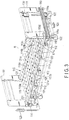
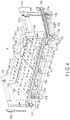
- a bed device B shown in FIG. 1 to FIG. 4 comprises a base frame 101 having a rectangular frame shape. Casters 102 are provided at four corners of the base frame 101.
- a stopper petal 103 is provided on one end side in the longitudinal direction of the base frame 101, and a pair of casters 102 positioned on the one end side in the longitudinal direction is held so as not to rotate by stepping on the stopper petal 103.
- the base frame 101 can be made to travel by the caster 102 and can be held so as not to travel by stepping on the stopper petal 103.
- a rectangular frame-shaped vertical frame (mounting frame) 105 larger than the base frame 101 is provided as a bed frame, on the upper surface side of the base frame 101. As shown in FIG. 1 , both end portions in the longitudinal direction of the vertical frames 105 and both end portions in the longitudinal direction of the base frame 101 are connected by vertical drive mechanisms 106 each formed of a link mechanism.
- the pair of vertical drive mechanisms 106 in the front and rear direction are linked by the link rod 107 so as to be interlocked, and are driven in the vertical direction in a horizontal state by the single vertical drive source 108 shown in the block diagram of FIG. 5 .
- First attachment portions 110 are provided at both end portions in the width direction of one end and the other end of the vertical frames 105 in the longitudinal direction.
- a board body 111 is provided to stand upright while leg portions 111a provided at both ends in the width direction are detachably inserted into each of the pair of attachment portions 110.
- side fences 1102 (not shown in FIG. 1 to FIG. 4 ) similar to side fences 1102 shown in FIG. 10 are held while two leg portions provided to protrude downward are detachably inserted into two adjacent second attachment portions 112.
- the attachment portions 112 are configured to be foldable with respect to the side surfaces of the vertical frame 105 in a state where the side fences 1102 are detached.
- a rocking frame (tilting frame) 115 is provided inside the frame of the vertical frame 105.
- Rollers 114a (only one is shown in FIG. 1 ) are provided at one end and the other end in the width direction, of both end surfaces in the longitudinal direction of the rocking frame 115, respectively.
- the rollers 114a are rotatably supported by receiving portions 114b (only one is shown in FIG. 1 ) provided at both ends in the longitudinal direction of the inner peripheral portion of the vertical frame 105.
- the rocking frame 115 is thereby supported so as to be able to tilt in the width direction (right and left direction) with the pair of rollers 114a provided at both longitudinal ends of either of one end and the other end in the width direction serving as a fulcrum.
- a tilting link mechanism (not shown) is provided at the vertical frame 105, and the tilting link mechanism is connected to the rocking frame 115.
- the tilting link mechanism is driven by a rocking drive source (tilting drive source) 116 shown in FIG. 5 .
- the rocking frame 115 When the rocking frame 115 is driven by the rocking drive mechanism including the rocking drive source 116, the rocking frame 115 is designed to be tilted in a direction in which the end on the side opposite to the fulcrum side rises where the rollers 114a provided at one end or the other end in the width direction via the link mechanism serve as the fulcrum.
- FIG. 4 shows a state in which the rocking frame 115 is driven to be tilted in one direction (left direction).
- a floor plate body 118 is provided on the upper surface of the rocking frame 115.
- the floor plate body 118 is composed of a central floor plate 119 having a size substantially corresponding to the outer dimensions of the rocking frame 115, and a pair of side floor plates 121 pivotally connected only upward, on both sides of the central floor plate 119 by hinges (not shown).
- each of the floor plates 119 and 121 is divided into a plurality of floor parts.
- the floor plates are composed of back floor parts 119a and 121a having two parts integrally connected, central floor parts 119b and 121b having one-side ends pivotally connected to one-side ends of the back floor parts 119a and 121a, first leg floor parts 119c and 121c having one-side ends pivotally connected to the other ends of the central floor parts 119b and 121b, and second floor parts 119d and 121d in pairs having one-side ends pivotally connected to the other ends of the first leg floor parts 119c and 121c.
- the central floor part 119b of the central floor plate 119 is fixed to the rocking frame 115.
- a pair of right and left side floor plates 121 provided on both sides in the width direction of the central floor plate 119 so as to pivot only in the upward direction by hinges have lower surfaces contacted and supported by contact members 123 (only one member shown in the drawing) provided on the upper surfaces of both sides in the width direction of the vertical frame 105.
- the rocking frame 115 is provided with a raise drive mechanism (not shown) on the lower surface side of the floor plate body 118 and a back-raising drive source 125 (shown in FIG. 5 ) for driving the raise drive mechanism.
- a raise drive mechanism (not shown) on the lower surface side of the floor plate body 118
- a back-raising drive source 125 (shown in FIG. 5 ) for driving the raise drive mechanism.
- the back-raising drive source 125 drives the raise drive mechanism
- the back floor parts 119a and 121a of the floor plate body 118 are driven in the raising direction, and the first and second leg floor parts 119c, 121c and 119d, 121d are driven to bend in a mountain shape, as shown in FIG. 1 and FIG. 2 .
- the first and second leg floor parts 119c, 121c and 119d, 121d can be set so as not to be driven when the back floor parts 119a and 121a of the floor plate body 118 are driven in the standing direction.
- Each of the drive sources 108, 116, and 125 is controlled by a control device 127 shown in FIG. 5 .
- the control device 127 is provided on the lower surface side of the vertical frame 105 although not shown in detail.
- the control device 127 includes a switching control unit 128 incorporating a storage unit (not shown).
- a remote controller 129 serving as a manual operation module and a setting controller 130 serving as a setting operation module are detachably connected to a switching control unit 128.
- the remote controller 129 and the setting controller 130 can be detachably engaged with the board body 111 as shown in FIG. 1 .
- a controller serving as control means is composed of the control device 127, the remote controller 129, and the setting controller 130.
- the remote controller 129 as shown in FIG. 6 , back raising operation buttons 131a and 131b for raising and lowering the back floor parts 119a and 121a of the floor plate body 118, and similarly, leg raising operation buttons 132a and 132b for raising and lowering the first and second leg floor parts 119c, 121c and 119d, 121d, raising and lowering buttons 133a and 133b for raising and lowering the vertical frame 105, tilting operation buttons 134a and 134b for tilting the rocking frame 115 rightward or leftward, and a horizontal position button 135 for returning the floor plate body 118 in the back-raising state, the leg-raising state or the tilting state to the horizontal state, are provided.
- a display 138 is provided at an upper part of the front surface of the setting controller 130 as shown in FIG. 7 .
- a power button 139, a switching button 141, a setting button 142, a start/stop button 143, a YES button 144, a NO button 145, and a pair of selection buttons 146 are provided on a lower part of the display 138.
- the display 138 When the power button 139 is operated, the display 138 is activated.
- the switching button 141 When the switching button 141 is pressed, the manual mode (or the manual operation limit mode) and the automatic mode can be switched. Switching between the manual mode and the manual operation limit mode can be performed by pressing the start/stop button 143 for a long time. At this time, switching between the manual mode and the manual operation limit mode cannot be performed unless the floor plate body 118 is in a horizontal state. Therefore, in this case, the floor plate body 118 is made horizontal by the manual operation, that is, the remote controller 129, and then the switching button 141 is operated.
- the manual mode is a mode for performing an operation by the remote controller 129, and switching to the manual mode is displayed as [manual operation] on the display 138.
- the raising angle and the tilting angle in the tilting direction, of the back floor parts 119a and 121a and the leg floor parts 119c, 121c, 119d, and 121d of the floor plate body 118, the elevation height of the vertical frame 105, etc., are displayed on the display 138.
- the raise drive of the floor plate body 118 and the tilting drive of the rocking frame 115 can be performed by the remote controller 129 without restriction, within the maximum drivable range set by an encoder or a limit switch (not shown).
- the back floor parts 119a and 121a of the floor plate body 118 can be raised within a predetermined range, at an angle of 0 to 72 degrees in this embodiment, and the rocking frame 115 is tilted rightward and leftward at an angle of 0 to 25 degrees. Furthermore, the leg floor parts 119c and 121c can be raised at an angle of 0 to 24 degrees.
- the floor parts are wholly bent in a mountain shape by interlocking one-side ends of the leg floor parts 119d and 121d in association with the rise of the leg floor parts 119c and 121c.
- the mode can be changed to the manual operation limit mode.
- [manual operation (limited)] is displayed on the display 138.
- the switching is displayed as [manual operation (limited)] on the display 138. If the setting button 142 is pressed in this state, settings of each function in the manual operation limit mode can be performed.
- the rocking frame 115 in a state in which the back floor parts 119a and 121a of the floor plate body 118 are raised within a predetermined range, i.e., an angle range of 0 to 15 degrees in the present embodiment, the rocking frame 115 can be driven to be tilted similarly within a predetermined range, i.e., an angle range of 0 to 5 degrees.
- These drive ranges are set by encoders or limit switches (not shown), similarly to the manual mode.
- the back-raising angle of the back floor parts 119a and 121a of the floor plate body 118, and the tilting angle of the rocking frame 115 are limited within the above range so as to be smaller than those in the manual mode, by the remote controller 129.
- the raising angle of the back floor parts 119a and 121a of the floor plate body 118 and the tilting angle of the rocking frame 115 are not limited to the above-described ranges, but are determined under conditions such as the width dimensions of the floor plate body 118, the length dimensions of the back floor parts 119a and 121a, and the distance between the floor plate body 118 and the side fence.
- the automatic operation is an operation of converting the tilt of the rocking frame 115 in the rightward direction and the leftward direction for each predetermined time.
- the setting items displayed on the setting screen are selected by the selection button 146 and the YES button 144 is pressed, similarly to the settings of the manual operation. If setting that is not in the setting items displayed on the setting screen is to be performed, the NO button 145 is pressed to change the setting items displayed on the setting screen, and the YES button 144 is pressed when the desired setting item is displayed, and the setting can be performed.
- the operation time of the rocking frame 115 can be set to be up to, for example, 24 hours at maximum by the rocking drive source 116, and, the angle of tilting the rocking frame 115 to the rightward direction and the leftward direction can be set within the range of, for example, 5 to 20 degrees. Furthermore, the stop time in the state where the rocking frame 115 is tilted in the rightward direction and the leftward direction can be set within the range of 2 minutes to 6 hours.
- the start/stop button 143 When the start/stop button 143 is operated in the state of switching to the automatic mode, it can be confirmed whether to start the automatic operation. If the YES button 144 is pressed in this state, the automatic operation is started under preset setting conditions. The automatic operation cannot be started when the floor plate body 118 is not horizontal and, in this case, the floor plate body 118 is automatically returned to the horizontal position and the automatic operation is started.
- start/stop button 143 If the start/stop button 143 is pressed during the automatic operation, the automatic operation is stopped. If the floor plate body 118 is not horizontal at the stop, the floor plate body is automatically returned to the horizontal position and then the automatic operation is started. When the previous automatic operation is suspended and then the automatic operation is restarted by pressing the start/stop button 143, it can be selected whether to continue the operation from the middle of the previous automatic operation or newly restart the operation.
- the operating conditions of the manual mode, the manual operation limit mode, and the automatic mode set by the setting controller 130 are stored in a storage unit (not shown) provided in the switching control unit 128 of the control device 127.
- the data of each operating condition stored in the storage unit of the switching control unit 128 can be copied to, for example, a storage medium such as an SD card, which is detachably provided to the setting controller 130.
- the setting controller 130 can set a plurality of operating conditions for each of the manual mode, the manual operation limit mode, and the automatic mode, and store the operating conditions in the storage unit of the switching control unit 128. Desired operating conditions can be thereby selected and executed in each operation mode.
- the operating conditions set in the setting controller 130 are copied to the storage medium, the operating conditions can be copied to a setting controller of the same structure provided in the other bed device by the storage medium.
- the operating conditions of the plurality of bed devices can be set easily and quickly.
- an input unit 151 is connected to the switching control unit 128 provided in the control device 127.
- the power button 139 of the setting controller 130 is turned on and the operation mode of the bed device B is set to the manual mode, the manual operation limit mode, or the automatic mode by the switching button 141, the setting conditions of the selected operation mode are output from the setting controller 130 to the switching control unit 128.
- an operation signal corresponding to the operation of each operation button of the remote controller 129 is output to the input unit 151 through the switching control unit 128, based on the operating conditions of the manual mode.
- the operation signal output to the input unit 151 is output to the processing unit 152 and processed, and then output to a drive output unit 153.
- drive signals corresponding to the operations of the remote controller 129 are output from the drive output unit 153 to each of the drive sources 108, 116, and 125.
- the operation of raising and lowering the floor plate body 118, the operation of tilting the rocking frame 115, the vertical drive of the vertical frame 105 or the like is performed in response to the operation of the remote controller 129.
- the rocking frame 115 is set to be unable to be driven in the inclination direction in a state in which the back floor parts 119a and 121a of the floor plate body 118 are raised as described above.
- the raise drive of the floor plate body 118 and the tilting drive of the rocking frame 115 can be performed simultaneously, but the drive operation is performed within a range limited under the conditions output from the setting controller 130 to the switching control unit 128.
- the back-raising angle of the floor plate body 118 and the tilting angle of the rocking frame 115 are limited to the range set by the setting controller 130.
- the rocking frame 115 can be thereby tilted in a state in which the back floor parts 119a and 121a of the floor plate body 118 are raised.
- the raised back floor parts 119a and 121a and the tilting angle of the rocking frame 115 are limited, the raised back floor parts 119a and 121a do not collide with the side fence 1102 even if the rocking frame 115 is tilted.
- the operation time of the rocking frame 115 operated by the rocking drive source 116 and the tilting drive of the rocking frame 115 to the rightward and leftward directions are performed by means of the control device 127, based on the conditions set by the setting controller 130.
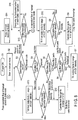
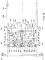
- FIG. 8 is a flowchart illustrating the operation in the manual mode, and the power button 109 of the setting controller 130 is operated to turn on the power in step 1 (step is hereinafter referred to as S), and the setting controller 130 is activated in the manual mode in S2.
- the operation mode is selected.
- the manual mode of the manual mode and the manual operation limit mode, it is asked which of the horizontal tilt (turnover) of the floor plate body 118, the leg raise and the back raise is selected by the remote controller 129 in S4.
- turnover that is, tilting drive of the rocking frame 115 is selected, it is asked whether the back floor parts 119a and 121a of the floor plate body 118 are horizontal or not in S5. If YES, it is asked whether the leg floor parts 119c, 121c, 119d, 121d are horizontal or not in S6. If the leg floor parts are horizontal, that is, YES, the rocking frame 115 can be driven in the horizontal direction within the set range, for example, the drivable range of 0 to 25 degrees in S7.
- leg raise i.e., the leg raise to drive the leg floor parts 119c, 121c, 119d, and 121d is selected in S4.
- the back raise is selected in S4, it is asked whether the floor plate body 118 (rocking frame 115) is horizontal with respect to the horizontal direction or not in S11 and, if YES, the back floor parts 119a and 121a of the floor plate body 118 can be raised within the maximum drivable range of, for example, 0 to 72 degrees in S12.
- the floor plate body 118 is driven horizontally in the range of, for example, 0 to 25 degrees in S13 and is horizontally driven, and the flow returns to S11. If NO, i.e., the leg floor parts 119c, 121c, 119d, and 121d are not horizontal in S6, the leg floor parts are returned to a horizontal position in S9 and then driven within the range of 0 to 25 degrees in the direction in which the floor plate body 118 is tilted horizontally in S7.
- each of the back-raising drive of the floor plate body 118, the tilting drive (turnover) in the lateral direction, and the leg raise can be performed in the range of from 0 degrees to a sufficiently large angle.
- back-raising drive or leg-raising drive cannot be performed.
- the floor plate body 118 cannot be driven in the horizontal direction in a state in which the back floor parts 119a and 121a are raised.
- the switching button 141 provided on the setting controller 130 is pressed to select the manual operation limit mode in the direction of YES, in S17.
- S18 it is asked which of the horizontal tilt (turnover) of the floor plate body 118, the leg raise and the back raise is selected by the remote controller 129.
- the floor plate body 118 can be tilted within the range of 0 to 5 degrees in the lateral direction by the operation of the remote controller 129, together with the rocking frame 115, in S19. That is, in the manual operation limit mode, the floor plate bodies can be tilted in the lateral direction within a tilt range smaller than the range of 0 to 25 degrees in the manual mode.
- the flow returns to S18 since the leg raise operation is prohibited in S20 in the manual operation limit mode. If back raise is selected in S18, the back floor parts 119a and 121a can be raised within a range of angles of 0 to 15 degrees, which is smaller than the range of 0 to 72 degrees in the manual mode, even if the floor plate body 118 is tilted in the lateral direction in S21.
- the tilting drive of the rocking frame 115 in the lateral direction of S19 is first performed and then the back-raising drive of S21 is performed later, but any one of the drives may be first performed.
- the floor plate body 118 is made horizontal by the operation of the horizontal button 135 or the other operation button provided on the remote controller 129 in S24, and then the flow returns to S23 and returns from B of the YES direction to B of the flowchart shown in FIG. 8 to enable the operation in the manual mode.
- the manual mode, the manual operation limit mode, or the automatic mode can be switched and the drive of each portion can be controlled by the setting controller 130.
- the back floor parts 119a and 121a of the floor plate body 118 can be driven in the raising direction within the range of 0 to 72 degrees, and the first and second leg floor parts 119c and 121c can be tilted within the range of 0 to 24 degrees.
- the rocking frame 115 can be tilted within a range of 0 to 25 degrees in the leftward or rightward direction.
- the rocking frame 115 cannot be tilted in the horizontal direction unless the back floor parts 119a and 121a and the first and second leg floor parts 119c, 121c, 119d, and 121d are in a horizontal state.
- the rocking frame 115 can be tilted in the horizontal direction even in the state in which the back floor parts 119a and 121a of the floor plate body 118 are raised.
- the raising angle of the back floor parts 119a and 121a is limited to a range of 0 to 15 degrees, which is a sufficiently small angle as compared with the manual mode, and the tilting angle of the rocking frame 115 in the lateral direction is limited to a range of 0 to 5 degrees.
- the patient can be easily and reliably maintained in a posture suitable for tube feeding and the like by raising the back floor parts 119a and 121a and tilting the rocking frame 115 as described above.
- the back floor parts 119a and 121a can be prevented from colliding with the side fence 1102 provided to erect at the end of the width direction of the vertical frame 105, similarly to the prior art shown in FIG. 10 , even if the rocking frame 115 is tilted in the state where the back floor parts 119a and 121a are raised.
- the raising angle of the back floor parts is set to 0 to 15 degrees and the tilting angle of the rocking frame in the lateral direction is set to 0 to 5 degrees, but these angles may be within a range which prevents the back floor parts from colliding with the side fence when the rocking frame is tilted in a state in which the back floor parts are raised.
- the raising angle and the tilting angle are varied under the conditions such as the distance between the side fence provided to erect at the end of the vertical frame in the width direction and both ends of the rocking frame in the width direction, the height dimension of the side fence, or the length dimension of the raised portion of the back floor parts, and since the angles are set in accordance with these conditions, the angles are not limited within the angle ranges described above.
- the point is that the raising angle and the tilting angle in the manual operation limit mode are set to be smaller than those in the manual mode.
- bed devices B of the second to fifth embodiments will be described.
- the constituent elements that are the same as or similar to the constituent elements described in the first embodiment are considered with reference to the corresponding descriptions of the first embodiment, and explanations are omitted here.
- the constituent elements other than those described below are the same as those of the first embodiment.
- each of the bed devices B comprises a controller capable of controlling a rocking drive source and a back-raising drive source in a manual mode in which when either the rocking frame and the floor plate body is in the horizontal state the other can be driven, and a manual operation limit mode in which when either of the rocking frame and the floor plate body is driven in a limited range the other can be driven within a limited range.
- the floor plate body on which the user lies on the back can be thereby subjected to vertical drive, back-raising drive, and rocking drive in the width direction.
- a second embodiment of the present invention will be described hereinafter with reference to FIG. 11 to FIG. 26 .
- the second embodiment is different from the first embodiment with respect to a feature of further comprising a rocking drive unit detachably provided on the bed frame.
- the rocking drive unit includes a rocking drive source.
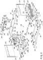
- FIG. 11 is an exploded perspective view
- FIG. 12 is a plan view
- FIG. 13 is a front view showing the bed device B according to the second embodiment.
- the bed device comprises a base frame 201.
- the base frame 201 includes a pair of longitudinal members 202 opposed and spaced apart in parallel, and both end parts in the longitudinal direction of the longitudinal members 202 are connected by lateral members 203 and formed in a rectangular shape.
- Leg members 204 are provided on both ends of the vertical members 202.
- Attachment members 206 having connection members 205 at their ends are provided upright at both end parts of the lateral members 203.
- a vertical frame 209 that serves as a bed frame formed in a rectangular shape having a planar shape larger than the base frame 201 is provided to be able to be driven vertically as explained later.
- the vertical frame 209 is divided into a first frame part 209A and a second frame part 209B each having a bracket shape.
- Each of the frame parts 209A and 209B is composed of a pair of longitudinal members 211 and a lateral member 212 connected to ends in the longitudinal direction of the longitudinal members 211.
- the pair of longitudinal members 211 of the first frame part 209A and the pair of longitudinal members 211 of the second frame part 209B are connected to be able to be disassembled.
- the vertical frame 209 is therefore formed in a rectangular shape.
- a pair of first support members 215 are provided on both ends in the longitudinal direction of the lateral member 212 to allow leg portions 214 of a board body 213 to be inserted into the respective support members and supported.
- Second support members 216 for supporting side fences (not shown) are axially supported to be bendable, on outer side surfaces of the lateral member 212.
- a vertical drive mechanism 219 that is divided into the first frame part 209A and the second frame part 209B to vertically drive the vertical frame 209 is provided at the vertical frame 209.
- the vertical drive mechanism 219 includes a pair of brackets 218 having ends (upper ends) connected to the pair of longitudinal members 211 of each of the first frame part 209A and the second frame part 209B.
- a shaft member 221 (not shown) is pivotally attached to a lower end of each of the brackets 218.
- Both end parts of an arm shaft 220 are connected to a pair of shaft members 221, respectively.
- One-side ends of vertical arms 222 are fixed to both end parts of the arm shaft 220.
- the other end of each of the vertical arms 222 is pivotally attached to the connection member 205 at an upper end of the attachment member 206 provided upright on the base frame 201.
- a vertical drive source 223 is pivotally attached to a middle part of the lateral member 212.
- the vertical drive source 223 includes a drive shaft (not shown) driven in a linear direction.
- a first movable rod 224 is connected to the drive shaft.
- An end of the first movable rod 224 is pivotally attached to an arm (not shown) having an end connected to the middle part of one arm shaft 220, and an end of a second movable rod 225 is pivotally attached to the other end of the first movable rod 224 so as to be able to be disassembled.
- the other end of the second movable rod 225 is pivotally attached detachably to a pair of arms 226 provided at a middle part of the other arm shaft 220.
- the first and second movable rods 224 and 225 are interlocked with the drive movement.
- the vertical arms 222 are pivotally supported by the connecting portion 205 provided at the upper end of the attachment member 206, the vertical arms 222 pivot with the connecting portion 205 serving as a fulcrum. Accordingly, the vertical frame 209 is driven in the upward or downward direction according to the pivoting direction.
- the pair of vertical members 211 of the second frame portion 209B of the vertical frame 209 are provided with a pair of receiving elements 227 forming receiving portions so as to protrude to the inner surface side, respectively.
- the receiving element 227 is formed by bending a plate member in a substantially U-letter shape.
- a rocking drive unit 229 is detachably attached to four receiving elements 227 as explained later.
- a rocking frame 231 driven to rock in the width direction by the rocking drive unit 229 is provided on an upper surface of the vertical frame 209.
- the rocking frame 231 is formed in a rectangular shape smaller than the vertical frame 209, by a pair of longitudinal members 231a arranged to be opposed and spaced apart in parallel and a pair of lateral members 231b connecting one-end parts and the other end parts in the longitudinal direction of the longitudinal members 231a.
- a floor plate body 232 is provided on the upper surface of the rocking frame 231 as shown in FIG. 12 and FIG. 13 .
- one of the lateral members 231b is provided at an inner position in the longitudinal direction than distal ends of the pair of longitudinal members 231a.
- the floor plate body 232 is constituted by a blow-molded central floor plate 233 and a pair of side floor plates 234 pivotally connected only upward to both sides of the central floor plate 233 in the width direction.
- Each of the floor plates 233 and 234 is divided into a plurality of floor parts pivotally connected to one another or, in the second embodiment, five floor parts 233a to 233e and 234a to 234e.
- the width dimension of the central floor plate 233 is set to be larger than the width dimension of the rocking frame 231, and the only floor part 233c located at the central portion in the longitudinal direction of the central floor plate 233 is fixed to a pair of plate members 230 provided on the rocking frame 231.
- a width dimension of the entire floor plate body 232 is set to be larger than a width dimension of the vertical frame 209.
- a pair of attachment members 235 are provided on both inner surfaces of the rocking frame 231, and a back-raising drive unit 236 is detachably provided on these attachment members 235.
- the back-raising drive unit 236 includes a housing 236a, and a back-raising drive source 237 is provided on one side surface of the housing 236a.
- the back-raising drive source 237 is driven, the first rotary shaft 238 provided on one end side of the housing 236a in the longitudinal direction and the second rotary shaft 239 provided on the other end side can be driven to rotate simultaneously or the only first rotation shaft 238 can be selected and driven to rotate.
- Proximal ends of back raising arms 242 having back-raising rollers 241 rotatably provided on the distal ends are fixed to the first rotary shaft 238, and proximal ends of leg raising arms 244 having leg raising rollers 243 rotatably provided on the distal ends are fixed to the second rotary shaft 239.
- the back raising roller 241 is located on the lower surface of the floor part 233e of the central floor plate 233, and the leg raising roller 243 is located on the lower surface of the floor part 234b of the central floor plate 233.
- the back raising arms 242 are driven in the upward direction, the floor parts 233e and 234d of the central floor plate 233 and the floor parts 234e and 234d of the side floor plate 234 are driven in the upward direction to raise the user's upper body.
- the floor part 233b of the central floor plate 233 and the floor parts 233b and 234b of the side floor plates 234 are driven in the upward direction, and the floor part 233a of the central floor plate 233 and the floor parts 234a of the side floor plates 234 are interlocked with the drive and bent in a mountain shape.
- the user's leg is held in a state of being bent upward from the knee.
- a pair of second receiving rollers 246 for supporting the rocking frame 231 to be able to rock in the width direction on the vertical frame 209 are provided rotatably with the axis set horizontally as explained later.
- the rocking drive unit 229 includes a frame 250 formed in a rectangular frame shape by a pair of lateral members 248 spaced apart in parallel at a predetermined interval and a pair of longitudinal members 249 connected to both ends of the lateral members 248.
- the length dimension of the lateral members 248 is set to be slightly shorter than the interval between the inner surfaces of the pair of longitudinal members 211 of the vertical frame 209.
- Bearings 252 are provided at central portions in the longitudinal direction of the pair of lateral members 248, and an attachment shaft 253 is provided on the bearings 252 with both end portions in the longitudinal direction rotatably supported.
- One-side ends of an L-shaped arm 254 and linear straight rod arm 255 are attached to a middle part of the attachment shaft 253.
- the rocking drive unit 229 is provided with a rocking drive mechanism 257.
- the rocking drive mechanism 257 includes a screw shaft 258.
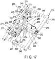
- the screw shaft 258 is covered with a bellows member 259 formed of resin to be extensible. As shown in FIG. 17 , one end of the screw shaft 258 exposed from the bellows member 259 is pivotally attached to a bracket 261 provided on one of longitudinal members 249 of the frame 250.
- a drive portion 263 including a rocking drive source 262 is provided so as to protrude in one side direction intersecting the axial direction of the screw shaft 258.
- the other side ends of the L-shaped arm 254 and straight rod arm 255 are connected to the driving portion 263.
- the L-shaped arm 254 is provided on one side of the drive portion 263 protruding from the direction intersecting the axial direction of the screw shaft 258, and the straight rod arm 255 is provided on the other side.
- the drive 263 side is the L-shaped arm 254 and interference with the drive 263 is thereby prevented.
- a female screw body (not shown) is screwed on the screw shaft 258.
- the female screw body is driven to rotate by the rocking drive source 262.
- the screw shaft 258 is axially driven relative to the female screw body.
- the screw shaft 258, that is, the rocking drive mechanism 257 rocks according to the rotational driving direction of the screw shaft 258 together with the screw shaft 258 with one end pivoted to the bracket 261 that serves as a fulcrum.
- the attachment shaft 253 to which the L-shaped arm 254 and the straight rod arm 255 are connected thereby rotates in accordance with the rocking direction.
- a belt-like drive link 266 having a guide shaft 265 provided to protrude at the lower end together with a pair of arms 254 and 255 is attached to the attachment shaft 253.
- the guide shaft 265 is slidably inserted into long holes 267a and 268a formed along one-end sides of the first rocking link 267 and the second rocking link 268.
- the other ends of the first rocking link 267 and the second rocking link 268 are pivotally attached to one end of a connection link 269 by a connection shaft 271. Furthermore, one end and the other end of the restriction link 272 (shown in FIG. 15 and FIG. 17 ) are pivotally attached to the pair of connection shafts 271 together with the other ends of the first rocking link 267 and the second rocking link 268.
- the restriction link 272 is curved in an arc shape as shown in FIG. 24 .
- connection links 269 are connected to one-side ends of attachment shafts 273, respectively.
- First receiving rollers 274 are rotatably attached to the other ends of the pair of attachment shafts 273. Furthermore, middle parts of the pair of attachment shafts 273 pass through one end and the other end of a column-shaped prismatic attachment member 275.
- the attachment member 275 is provided integrally with the attachment shafts 273.
- the link mechanism 270 is constituted by the drive link 266, the first rocking link 267, the second rocking link 268, the pair of connection links 269, and the restriction link 272.
- one bearing 252 supporting the attachment shaft 253 located on the attachment member 275 side is provided with a pair of positioning portions 252a opposed and spaced apart at a small interval on one side surface of the central part in the longitudinal direction of the attachment member 275. The attachment member 275 is thereby restrained from rocking in the longitudinal direction.
- inverted L-shaped attachment elements 276a are provided at both ends of one of lateral members 248 of the frame 250.
- Inverted L-shaped engagement members 276 are also provided on the attachment elements 276a so as to adjust the attachment position in the vertical direction.
- connection shafts 271 engages with one of the engagement members 276 and the other connection shaft 271 is not in a state of engaging with the other engagement member 276.
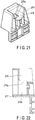
- the first receiving member 277 is hollow, and a recess portion 278 having a U-shaped curved surface opened at the upper surface is formed on the first receiving member 277.
- the curved surface of the recess portion 278 is set to be a curved surface having the same curvature as the curved surface of the first receiving roller 274.
- a limit switch 279 serving as a detector is provided in the space part 278b (shown in FIG. 22 ) formed below the recess portion 278 so as to be adjustable in position in the vertical direction.
- the limit switch 279 includes a detection lever 281.
- a distal end part of the detection lever 281 is made to protrude from an opening 278a formed to open at an inner bottom of the recess portion 278 of the first receiving member 277 shown in FIG. 21 and FIG. 22 . Then, the distal end part of the detection lever 281 is set to be slightly higher than the inner bottom surface of the recess portion 278.
- connection instruments 282 obtained by bending plate members in an inverted U shape are provided on one-side surfaces of both end parts of the attachment member 275, respectively.
- One-side ends of rocking frames 231c that is, the ends of the rocking frame 231 opposite to the ends provided with the second receiving rollers 246 are connected to the pair of connection instruments 282.
- the rocking drive unit 229 is detachably attached to the second frame portion 209B of the vertical frame 209 before the rocking frame 231 is connected to the attachment member 275 by the connection instruments 282.
- both end parts of the pair of lateral members 248 of the frame 250 are detachably held and engaged with the pair of receiving elements 227 provided on the inner surfaces of the pair of longitudinal members 211 of the second frame part 209B.
- first through holes 227a are formed on a pair of side edges of the receiving element 227, and second through holes 248a corresponding to the first through holes 227a are formed at both end parts of the lateral member 248.
- the lateral member 248 When the lateral member 248 is engaged with the receiving element 227, the lateral member 248 is located to correspond to the first through holes 227a and the second through holes 248a.
- a connection shaft 287 is inserted into the corresponding first through holes 227a and the second through holes 248a.
- the rocking drive unit 229 is thereby detachably attached to the second frame portion 209B of the vertical frame 209.
- a flexible band member 288 formed of resin is integrally connected to the connecting shaft 287, the middle part of the band member 288 is fixed to the lower surface of the receiving element 227, and a holding hole 289 is formed in the other end of the band member.
- connection shaft 287 is thereby held so as not to be detached.
- the rocking drive unit 229 can be detachably attached to the second frame portion 209B of the vertical frame 209 by the connection shaft 287.
- connection structure using the connection shaft 287 provided with the band member 288 explained above is also applied to the other connecting portion of the second embodiment.
- a pair of second receiving rollers 246 provided on one of end surfaces of the rocking frame 231 are supported by a recess portion 284 formed at a pair of second receiving members 283 (shown in FIG. 11 ) provided on both end parts on inner surface sides of the lateral member 212 of the first frame part 209A of the vertical frame 209.
- the recess portion 284 of the second receiving member 283 is formed to have a concave surface having a curved surface of the same curvature as the outer peripheral surface of the second receiving roller 246, similarly to the first receiving member 277.
- a vertical drive source 223, a back-raising drive source 237, and a rocking drive source 262 is controlled by a control device 285. Detection signals of a pair of limit switches 279 are input to the control device 285. Furthermore, a remote controller 286 is connected to the control device 285, and the drive of the vertical drive source 223, the back-raising drive source 237, and the rocking drive source 262 can be operated by the remote controller 286.
- the back-raising drive source 237 can be operated to drive the back raise of the back-raising floor plate body 232.
- the rocking frame 231 is rocked, only one of the pair of right and left limit switches 279 is turned on and the other is turned off.
- the drive of the rocking drive source 262 is controlled such that the control device 285 drives the rocking drive source 262 to enable the rocking frame 231 to rock.
- the limit switch 279 is provided with the detection lever 281 facing the inner bottom part of the recess portion 278 of the first receiving member 277. Since the recess portion 278 has a concave surface shape, the recess portion reliably supports the first receiving roller 274. For this reason, when the rocking frame 231 is bent by an external force or the like and the first receiving roller 274 slightly floats in the recess portion 278, the limit switch 279 can reliably detect this matter.
- the rocking drive source 262 when the rocking drive source 262 is operated, the rocking drive source 262 and the driving portion 263 are moved in a predetermined direction along the screw shaft 258, for example, from the state shown in FIG. 24 to the leftward direction as shown in FIG. 25 . Since the guide shaft 265 moves the long hole 267a of the first rocking link 267 in the direction represented by arrow a in FIG. 25 , the drive link 266 rotates clockwise as represented by arrow X in FIG. 25 , together with the attachment shaft 253.
- connection links 269 When one of the connection links 269 rises, one end side in the width direction of the rocking frame 231 connected to the connection link 269 via the attachment shaft 273 and the attachment member 275 rises together with one of the first receiving rollers 274.
- the other end side of the rocking frame 231 in the width direction pivots while the other first receiving roller 274 provided at the other end in the longitudinal direction of the attachment member 275 and supported by the first receiving member 277, and the second receiving roller 246 provided at the other end in the width direction of the other end surface in the longitudinal direction and supported by the second receiving member 283 serve as fulcrums.
- the rocking frame 231 has one end side in the width direction raised and is tilted.
- the pair of first receiving members 277 are arranged close to the other side surface of the attachment member 275. Therefore, when the attachment member 275 is in the horizontal state as shown in FIG. 24 and FIG. 15 , rocking in the direction intersecting the longitudinal direction is prevented by the first receiving member 277 and the positioning portion 252a provided on one of the bearings 252.
- connection link 269 Since the lower ends of the pair of connection links 269 are connected by the restriction link 272, the distance between the lower ends of the pair of connection links 269 does not change. In addition, the position of the lower end of the connection link 269 in the downward position does not shift in the leftward direction or the upward direction in FIG. 25 by engaging one of the connection shafts 271 with one of the engagement members 276.
- connection link 269 having an upper end connected to the one end part in the upward direction is reliably displaced from the downward position to the upward position without being shifted to the leftward direction together with the attachment member 275, and one end side in the width direction of the rocking frame 231 is thereby raised reliably.
- the guide shaft 265 is moved from the state shown in FIG. 24 in the direction opposite to that shown in FIG. 25 , that is, in the direction represented by arrow b in FIG. 26 .
- the rocking frame 231 can be made to rock in an opposite direction, i.e., a direction in which the other end side in the width direction is raised.
- connection shafts 271 engages with the L-shaped engagement member 276. Therefore, since the connection shaft 271 is reliably held by the engagement member 276, the rocking frame 231 may hardly rattle even if an inadvertent external force is applied to the rocking frame 231 which has rocked.
- the engagement member 276 is attached to the attachment instrument 276a so as to be adjustable in position. For this reason, the engagement member 276 can also be therefore positioned such that the connection shaft 271 engages with the engagement member 276 without rattling.
- the attachment member 275 to which the rocking frame 231 is connected is provided at the frame 250 so as to be able to rock, and furthermore, the link mechanism 270 for rocking the attachment member 275 and the rocking drive mechanism 257 for driving the link mechanism 270 are provided integrally with the frame 250.
- the rocking drive unit 229 in which the attachment member 275 for rocking the rocking frame 231, the link mechanism 270, and the rocking drive mechanism 257 are integrated can be configured.
- the end part of the lateral member 248 of the frame 250 is engaged with the receiving element 227 provided on the vertical frame 209, and they are connected by the connection shaft 287 so as to be disassembled as shown in FIG. 18 , and the rocking drive unit 229 can be thereby detachably assembled to the vertical frame 209.
- the above-described main components for driving the rocking frame 231 to rock are integrated by the rocking drive unit 229.
- the rocking drive unit 229 can be detachably assembled to the first frame part 209A of the vertical frames 209 quickly and easily without any skill.
- the vertical frame 209 is disassembled into first and second frame portions 209A and 209B, and the rocking drive unit 229 is disassembled with respect to the vertical frame 209.
- the vertical frame 209 divided into the first and second frame parts 209A and 209B is more lightweight than that in the assembled state, and furthermore, the vertical frame 209 is more lightweight as compared to the case where the rocking drive unit 229 is incorporated in the vertical frame 209, and their conveying operation and assembling operation can be therefore performed quickly and easily.
- the pair of first receiving members 277 for supporting the pair of first receiving rollers 274 are provided at the attachment member 275 to which the rocking frame 231 is connected, and the limit switches 279 are provided at the first receiving members 277, respectively.
- the control device 285 stops the driving of the rocking frame 231 in the rocking direction when an unnecessary external force is applied to the rocking frame 231 in the rocking state, one of the first receiving rollers 274 located on the lower side in the rocking direction of the rocking frame 231 floats from the first receiving member 277, and one of the limit switches 279 provided on the first receiving member 277 is turned off together with the other limit switch 279.
- an alarm means such as lighting of a lamp or sounding a buzzer notifies an abnormal state.
- the improvement in safety can be attempted.
- the control device 285 prevents a floor plate body 232 from being driven by a back-raising drive source 237.
- the control device 285 drives the rocking drive source 262 to prevent the floor plate body 232 from rocking.
- the limit switch 279 is provided with the detection lever 281 located at the inner bottom of the arc-shaped recess portion 278 on which the first receiving roller 274 of the first receiving member 277 is supported.
- the recess portion 278 is formed in an arc shape corresponding to the first receiving roller 274, and the first receiving roller 274 is thereby supported stably and reliably by the recess portion 278.
- the first receiving roller 274 slightly floats from the recess portion 278, this matter is reliably detected by positioning the detection lever 281 of the limit switch 279 at the inner bottom of the recess portion 278.
- the support state of the first receiving roller 274 in the recess portion 278 is accurately detected by the limit switch 279. For this reason, if an inadvertent external force is applied to the rocking frame 231 in the tilted state and the first receiving roller 274 on the lower end side of the rocking frame 231 in the rocking direction slightly floats from the recess portion 278, the limit switch 279 including the detection lever 281 in the recess portion 278 can detect this accurately and reliably. The control device 285 can thereby drive the bed device safely and reliably by the detection signal from the limit switch 279.
- the rocking drive unit 229 engages the both ends of the lateral member 248 of the frame 250 with the receiving element 227 provided on the second frame part 209B of the vertical frame 209, and the connection shaft 287 is inserted into the through holes 248a and 227a provided in the end part of the lateral member 248 and the receiving element 227 and attached to the vertical frame 209.
- connection shaft 287 is attached to one-side end of a flexible band member 288 formed of resin which is fixed to the middle part of the receiving element 227. For this reason, since the connection shaft 287 is prepared in advance at the connecting portion between the lateral member 248 and the receiving element 227, the attachment operation of the rocking drive unit 229 can be performed quickly.
- connection shaft 287 removed from the connecting portion between the receiving element 227 and the frame 250 is held integrally with the receiving tool 227 by the band member 288, there is no risk of losing even if it is removed from the connecting portion.
- the bed device including the vertical frame is described as an example in the above-described embodiments, but the bed device may not comprise the vertical frame. That is, in the above-described embodiment, the rocking drive unit is provided on the vertical frame as a bed frame but, in the case of a bed device comprising no vertical frame, the base frame may be used as a bed frame to attach the rocking drive unit.
- the limit switch serving as the detector is provided on the first receiving member for receiving the first receiving roller, but both the first and second receiving members or only the second receiving member may be provided.
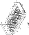
- a third embodiment of the present invention will be described hereinafter with reference to FIG. 27 to FIG. 40 .
- the third embodiment is different from the first embodiment with respect to a feature of further comprising a first receiving member provided integrally with a hinge.
- the first receiving member allows the side floor plate to pivot upward from a horizontal state with respect to the central floor plate and prevents the side floor plates from pivoting downward from a horizontal state.
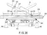
- the bed device B shown in FIG. 27 to FIG. 29 comprises a base frame 301 having four corner parts supported by leg members 302.
- a vertical frame 303 serving as a bed frame is provided to be driven vertically by a vertical drive mechanism 305 including a pair of right and left vertical links 304 as shown in FIG. 28 .
- the vertical frame 303 is formed to have a rectangular frame shape in plan view by a pair of longitudinal rods 306 opposed in parallel and spaced apart at a predetermined interval, and a pair of board bodies 307 attached to one-side ends and the other ends of the longitudinal rods 306 in an upright position.
- Bendable support members 308 for detachably attaching a side fence are provided and spaced apart with regular intervals in the longitudinal direction, on the outside surfaces of the pair of longitudinal rods 306 of the vertical frame 303.
- a rocking frame 311 shaped in a rectangular frame shape (shown in FIG. 27 ) is arranged in the frame of the vertical frame 303. That is, the rocking frame 311 is set in a width dimension so as to enter the inside of the vertical frame 303. Then, the rocking frame 311 is driven to rock in the width direction by a rocking drive mechanism 312 (shown in FIG. 28 ) provided at one end of the vertical frame 303 in the longitudinal direction.
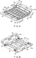
- a floor plate body 315 is provided on the upper surface of the rocking frame 311. As shown in FIG. 27 or FIG. 30 , the floor plate body 315 is constituted by a blow-molded central floor plate 317 and a pair of side floor plates 318 having upper end portions in the thickness direction pivotally connected to both sides of the central floor plate 317 in the width direction by a flexible thin portion 316. When the floor plate body 315 is molded, the thin portion 316 is molded simultaneously.
- the pair of side floor plates 318 are held in a lateral state with respect to the central floor plate 317 by the thin portion 316 and are pivotally connected only upward in the horizontal state with the connection portion of the thin portion 316 serving as a fulcrum and to be incapable of pivoting downward.
- the central floor plate 317 and the pair of side floor plates 318 are divided into plural floor parts 317a to 317d and 318a to 318d each having a predetermined length.
- the floor plates are divided into four parts, i.e., back floor parts 317a and 318a, two pairs of (two divisional) fixed floor parts 317b and 318b, first leg floor parts 317c and 318c, and second leg floor parts 317d and 318d.
- a back floor part 317a is pivotally connected to one end in the longitudinal direction intersecting the width direction, and a first leg floor part 317c and a second leg floor part 317d are sequentially connected pivotally to the other end.
- the width dimension of the central floor plate 317 is set to be substantially the same as the width dimension of the rocking frame 311.
- the pair of side floor plates 318 protrude outward in the width direction of the rocking frame 311.
- a back-raising drive unit 321 shown in FIG. 28 is provided on a lower surface side of the rocking frame 311.
- the back-raising drive source provided at the back-raising drive unit 321 is activated, the back floor parts 317a and 318a of the central floor plate 317 and the side floor plates 318 can be made to pivot integrally in the raising direction as represented by chained lines in the drawing.
- first leg floor parts 317c and 318c are pivotally driven in the raising direction while interlocked with the back floor part 317a and 318c or independently, and the second leg floor parts 317d and 318d are interlocked with this, such that both of the leg floor parts can raise the back floor parts in a substantially inverted V-shape.
- the floor plate 315 can be made to rock in the width direction together with the rocking frame 311 as represented by a chain line in FIG. 29 .
- the pair of side floor plates 318 provided on both sides of the central floor plate 317 can pivot in the only upward direction from a state of being horizontally maintained by the thin portion 316 with respect to the central floor plate 317 as explained above.
- the side floor plate 318 located on the upper side in the pivoting direction of the floor plate body 315 is maintained in a horizontal state, and the side floor plate 318 located on the lower side contacts the upper surface of the longitudinal rod 306 of the vertical frame 303 and pivots and bends upward from a relatively horizontal state with respect to the central floor plate 317.
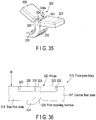
- both end parts in the longitudinal direction, of both ends in the width direction of the back floor part 317a, the first leg floor part 317c, and the second leg floor part 317d of the central floor plate 317, and one-side ends in the width direction of the back floor parts 318a, the first leg floor parts 318c, and the second leg floor parts 318d of the pair of side floor plates 318, are pivotally connected by pairs of hinges 322, respectively, as described later.
- the fixed floor part 317b of the central floor plate 317 and the fixed floor part 318b of the side floor plate 318 divided into two pieces are not connected by the hinges 322, but may be connected by the hinges 322.
- the hinge 322 includes a first connection element 323 as shown in FIG. 33 to FIG. 35 .
- the first connection element 323 has a rectangular plate shape in a plan view, and concave portions 324a opened on the upper surface and the side surface are formed at both ends in the width direction of one end of the first connection element 323. A pair of support portions 324 are thereby formed at one end of the first connection element 323.
- First support holes 324b are formed in the pair of support portions 324 in the thickness direction, and a connection shaft 325 is inserted into the support holes 324b and supported so as not to be extractable.
- One end part of a second connection element 326 having a rectangular plate in plan view is pivotally connected to the first connection element 323 by a connection shaft 325. That is, as shown in FIG. 33 , a protruding portion 327 is provided at the one end part of the second connection element 326, and a support hole 328 penetrating in the thickness direction is formed in the protruding portion 327.
- the second connection element 326 is connected pivotally. Since the protruding portion 327 is located inside the recess portion 324a, the second connection element 326 is provided to pivot in the only upward direction with respect to the first connection element 323. That is, the connection element pivots in the only upward direction, similarly to the side floor plates 318 of the floor plate body 315.
- a first receiving member 329 is molded integrally with the first connection element 323. That is, in the first receiving member 329, the substantially L-shaped side surface, and one end part is integrated with a lower surface part of a recess part 324a at which a pair of support portions 324 are formed, of the first connection element 323. The other end part of the first receiving member 329 is made to extend downward, bent toward the second connection element 323 side, and formed in the first engaging portion 331.
- the hinges 322 attach and fix the first connection elements 323 to recessed first attachment portions 332 formed on both end parts in the longitudinal direction of upper surfaces of the back floor parts 317a, the first leg floor parts 317c, and the second leg floor parts 317d of the central floor plate 317, and attach and fix the second connection elements 326 to recessed second attachment portions 333 formed at both end parts in the longitudinal direction of upper surfaces of the back floor parts 318a, the first leg floor parts 318c, and the second leg floor parts 318d of the side floor plate 318.
- FIG. 31 and FIG. 32 show the connected state of the back floor part 317a of the central floor plate 317 and the back floor part 318a of the side floor plate 318.
- the first engagement member 331 of the first receiving member 329 provided at the first connection element 323 of the hinge 322 engages with a lower surface of the end part in the width direction of the side floor plate 318.
- the first engagement portion 331 of the first receiving member 329 thereby prevents the side floor plate 318 in a horizontal state from pivoting downward.
- FIG. 37 shows a state in which the side floor plate 318 pivots upward from a horizontal state and, in this case, the first engagement member 331 of the first receiving member 329 does not prevent the side floor plate 318 from pivoting upward.
- the central floor plate 317 and the side floor plate 318 of the floor plate body 315 are pivotally connected by molding the thin portion 316 at the time of molding, but may be pivotally connected only by the hinge 322 without molding the thin portion 316.
- a first recess portion 335 is formed on the lower surface of the back floor part 317a of the central floor plate 317, along the entire length in the width direction.
- second recess portions 336 are formed at one-side ends in the width direction at positions corresponding to both ends of the first recess portion 335.
- FIG. 32 shows the back floor parts 317a and 318a of the floor plate body 315 and, similarly, first and second recess portions 335 and 336 are formed on the first and second leg floor parts 317c, 318c, 317d, and 318d.
- a second receiving member 337 such as a pipe member is detachably attached to the central floor plate 317 in the first recess portion 335.
- the second receiving member 337 is set to have the length that allows both end parts in the longitudinal direction to project laterally from the first recess portion 335, and the both end parts engage with second recess portions 336 when the side floor plates 318 are in the horizontal state.
- the second receiving member 337 thereby prevents the side floor plate 318 in a horizontal state from pivoting downward by its both ends together with the first receiving member 329. That is, when the side floor plates 318 are horizontal, both end parts of the second receiving member 337 serve as second engagement portions 338 that engage with the lower surfaces and support them.
- the side floor plates 318 are pivotally connected to the central floor plate 317 only upward in the horizontal state by the hinges 322 and the thin portions 316.
- the first engagement portion 331 of the first receiving member 329 provided integrally with the hinge 322 is engaged with the lower end surface in the width direction of the side floor plate 318.
- the side floor plate 318 is thereby prevented from pivoting downward by the first engagement portion 331 and, even if a load W (shown in FIG. 37 ) is inadvertently applied to the upper surface of the side floor plate 318, the side floor plate 318 is prevented from pivoting downward with the load W.
- a load W shown in FIG. 37
- the side floor plate 318 is prevented from pivoting downward, it is possible to prevent the connection of the side floor plate 318 using the hinge 322 from being damaged and the thin portion 316 connecting the central floor plate 317 and the side floor plate 318 from being broken.
- a second receiving member 337 is fixed to the central floor plate 317 in the first recess portion 335 and the second recess portion 336 formed on the lower surfaces of the central floor plate 317 and the side floor plate 318, and the lower surfaces of the pair of side floor plates 318 are supported by both ends of the second receiving member 337.
- FIG. 39 shows a fourth embodiment of the present invention.
- the fourth embodiment is different from the third embodiment with respect to a feature that the first receiving member 329 disclosed in the third embodiment is not provided at the hinge 322 which pivotally connects the central floor plate 317 and the side floor plates 318.
- third receiving members 341 having a substantially L-shaped side surface are provided on both side surfaces in the width direction of the central floor plate 317.
- one end part is provided integrally with the side surface of the central floor plate 317, and the other end part is extended downward and formed at a third engagement member 342 bent on the lower surface side of the side floor plates 318.
- the third receiving member 341 may be formed integrally with the central floor plate 317 or may be formed separately from the central floor plate 317 and provided integrally with the central floor plate 317 with a screw, an adhesive, or the like.
- FIG. 40 shows a fifth embodiment of the present invention.
- the fifth embodiment is a modified example of the fourth embodiment, but is different from the fourth embodiment with respect to a feature that third receiving members 341 are provided on the side surfaces of the side floor plates 318 opposed to the side surfaces of the central floor plate 317.
- the third receiving member 341 has one end part provided integrally with the side surface of the side floor plate 318 and, when the side floor plate 318 is in a horizontal state, a third engagement member 342 formed on the other end part engages with the lower surface of the end part in the width direction of the central floor plate 317.
- the third receiving member 341 may be formed integrally with the side floor plate 318, similarly to the fourth embodiment, or may be integrally attached to the side surface of the side floor plate 318 as a separate body.
- the bed device including the vertical frame is described as an example in the above-described embodiments, but the bed device may not comprise the vertical frame. That is, the vertical frame is exemplified as the bed frame provided with the rocking frame in the above-described embodiments but, in a bed device comprising no vertical frame, the base frame may be used as the bed frame and the rocking frame may be supported so as to rock at the bed frame.
- the center floor plate and a pair of side floor plates are divided into several parts such as a back floor part and a leg floor part, as a floor board body, to enable the back raise and leg raise, has been explained as an example, but the central floor plate and the side floor plates may not be divided into a plurality of parts as he floor plate body.
- the above-explained structures disclosed in the first to fifth embodiments can be combined arbitrarily.
- first leg floor part 119d, 121d, 233a, 234a, 317d, 318d... second leg floor part, 125, 237... back-raising drive source, 127, 285... control device, 128... switching control unit, 129, 286... remote controller (example of manual operation module), 130... setting controller (example of setting operation module), 151... input unit, 152... processing unit, 153... drive output unit, 1102... side fence, 229... rocking drive unit, 246... second receiving roller, 250... frame, 257, 312... rocking drive mechanism, 263...drive unit, 266... drive link, 267... first rocking link, 268... second rocking link, 270... link mechanism, 274... first receiving roller, 277...
- first receiving member 279... limit switch, 281... detection lever, 283... second receiving member, 316... thin portion, 322... hinge, 323... first connection element, 325... connection shaft, 329... first receiving member, 331... first engagement portion, 337... second receiving member, 338... second engagement portion, 341... third receiving member, 342... third engagement portion.
Landscapes
- Health & Medical Sciences (AREA)
- Nursing (AREA)
- Life Sciences & Earth Sciences (AREA)
- Animal Behavior & Ethology (AREA)
- General Health & Medical Sciences (AREA)
- Public Health (AREA)
- Veterinary Medicine (AREA)
- Invalid Beds And Related Equipment (AREA)
Applications Claiming Priority (4)
| Application Number | Priority Date | Filing Date | Title |
|---|---|---|---|
| JP2017039558A JP6550414B2 (ja) | 2017-03-02 | 2017-03-02 | ベッド装置 |
| JP2017187486A JP2019058575A (ja) | 2017-09-28 | 2017-09-28 | ベッド装置 |
| JP2017229028A JP2019097658A (ja) | 2017-11-29 | 2017-11-29 | ベッド装置 |
| PCT/JP2018/004870 WO2018159281A1 (ja) | 2017-03-02 | 2018-02-13 | ベッド装置 |
Publications (2)
| Publication Number | Publication Date |
|---|---|
| EP3574880A1 true EP3574880A1 (de) | 2019-12-04 |
| EP3574880A4 EP3574880A4 (de) | 2021-02-17 |
Family
ID=63370889
Family Applications (1)
| Application Number | Title | Priority Date | Filing Date |
|---|---|---|---|
| EP18761982.0A Withdrawn EP3574880A4 (de) | 2017-03-02 | 2018-02-13 | Bettvorrichtung |
Country Status (5)
| Country | Link |
|---|---|
| EP (1) | EP3574880A4 (de) |
| CN (1) | CN110381905B (de) |
| SG (1) | SG11201908046RA (de) |
| TW (1) | TWI743319B (de) |
| WO (1) | WO2018159281A1 (de) |
Cited By (1)
| Publication number | Priority date | Publication date | Assignee | Title |
|---|---|---|---|---|
| WO2023035026A1 (en) * | 2021-09-08 | 2023-03-16 | Burling Aged Care Solutions Pty Ltd | A bed for turning patients |
Families Citing this family (4)
| Publication number | Priority date | Publication date | Assignee | Title |
|---|---|---|---|---|
| JP7284638B2 (ja) * | 2019-06-05 | 2023-05-31 | パラマウントベッド株式会社 | 制御装置及び電動家具 |
| CN111544027B (zh) * | 2020-04-16 | 2024-08-09 | 深圳瀚维智能医疗科技有限公司 | 便携式扫查床及乳腺自动扫查设备 |
| CN116350440A (zh) * | 2023-04-11 | 2023-06-30 | 常州工学院 | 一种多功能电动翻身床 |
| TWI908652B (zh) * | 2025-04-11 | 2025-12-11 | 古洛奇國際有限公司 | 一鍵式電動床起身躺臥系統 |
Family Cites Families (12)
| Publication number | Priority date | Publication date | Assignee | Title |
|---|---|---|---|---|
| US5802640A (en) * | 1992-04-03 | 1998-09-08 | Hill-Rom, Inc. | Patient care system |
| JP2923412B2 (ja) * | 1993-06-18 | 1999-07-26 | フランスベッド株式会社 | ベッド装置 |
| JP2987290B2 (ja) | 1994-05-02 | 1999-12-06 | フランスベッド株式会社 | ベッド装置 |
| JP3362097B2 (ja) * | 1996-06-21 | 2003-01-07 | フランスベッド株式会社 | ベッド装置 |
| CN1408335A (zh) * | 2001-09-26 | 2003-04-09 | 王义龙 | 电动床及其运转控制方法 |
| JP2003111804A (ja) | 2001-10-09 | 2003-04-15 | France Bed Co Ltd | ベッド装置 |
| JP2003310668A (ja) * | 2002-02-22 | 2003-11-05 | Sanyo Electric Co Ltd | 可動ベッド |
| US9358168B2 (en) * | 2012-09-04 | 2016-06-07 | Hill-Rom Services, Inc. | Patient position detection for patient support surface |
| US10413462B2 (en) * | 2013-04-25 | 2019-09-17 | Paramount Bed Co., Ltd. | Bed apparatus and bed apparatus control method |
| EP3065687B1 (de) * | 2013-11-06 | 2018-12-26 | IDEAssociates (IOM) Limited | Bett |
| CN204636783U (zh) * | 2014-12-31 | 2015-09-16 | 北京中科健安医用技术有限公司 | 一种多功能电动护理床 |
| CN111166582A (zh) * | 2019-12-31 | 2020-05-19 | 肖梅 | 一种用于人员卧床检查的辅助翻动装置 |
-
2018
- 2018-02-13 CN CN201880015386.XA patent/CN110381905B/zh active Active
- 2018-02-13 EP EP18761982.0A patent/EP3574880A4/de not_active Withdrawn
- 2018-02-13 WO PCT/JP2018/004870 patent/WO2018159281A1/ja not_active Ceased
- 2018-02-13 SG SG11201908046RA patent/SG11201908046RA/en unknown
- 2018-02-26 TW TW107106343A patent/TWI743319B/zh active
Cited By (1)
| Publication number | Priority date | Publication date | Assignee | Title |
|---|---|---|---|---|
| WO2023035026A1 (en) * | 2021-09-08 | 2023-03-16 | Burling Aged Care Solutions Pty Ltd | A bed for turning patients |
Also Published As
| Publication number | Publication date |
|---|---|
| TW201836528A (zh) | 2018-10-16 |
| WO2018159281A1 (ja) | 2018-09-07 |
| TWI743319B (zh) | 2021-10-21 |
| CN110381905A (zh) | 2019-10-25 |
| CN110381905B (zh) | 2021-08-03 |
| EP3574880A4 (de) | 2021-02-17 |
| SG11201908046RA (en) | 2019-09-27 |
Similar Documents
| Publication | Publication Date | Title |
|---|---|---|
| EP3574880A1 (de) | Bettvorrichtung | |
| EP1541108A1 (de) | Bewegliches bett | |
| JP6550414B2 (ja) | ベッド装置 | |
| JP3362097B2 (ja) | ベッド装置 | |
| CN103747708B (zh) | 床的合体方法、床的分离方法及床 | |
| TWI260218B (en) | Adjustable bed mattress | |
| KR101317480B1 (ko) | 병원용 다기능 전동침대 | |
| WO2018105034A1 (ja) | 移乗装置 | |
| US20190150627A1 (en) | Bed device | |
| AU2021107374A4 (en) | Automated Adjustable Seating System | |
| JP2923412B2 (ja) | ベッド装置 | |
| HK40008542A (en) | Bed device | |
| CN209847652U (zh) | 一种病床左右倾斜装置 | |
| JP2005304820A (ja) | 寝返り支援ベッド | |
| JP4231363B2 (ja) | 背上げ式ベッド装置 | |
| KR20180129241A (ko) | 조립식 전동침대 | |
| HK40008542B (zh) | 床装置 | |
| JP2019058575A (ja) | ベッド装置 | |
| JP4802201B2 (ja) | リクライニング式ベッド | |
| JP3035465B2 (ja) | 起床式ベッド装置 | |
| JP3752412B2 (ja) | ベッド装置 | |
| KR102084011B1 (ko) | 공기청정기용 받침대 | |
| JP2019110976A (ja) | ベッド装置 | |
| US20250082529A1 (en) | Care bed | |
| JP2012245268A (ja) | 起床式ベッド装置 |
Legal Events
| Date | Code | Title | Description |
|---|---|---|---|
| STAA | Information on the status of an ep patent application or granted ep patent |
Free format text: STATUS: THE INTERNATIONAL PUBLICATION HAS BEEN MADE |
|
| PUAI | Public reference made under article 153(3) epc to a published international application that has entered the european phase |
Free format text: ORIGINAL CODE: 0009012 |
|
| STAA | Information on the status of an ep patent application or granted ep patent |
Free format text: STATUS: REQUEST FOR EXAMINATION WAS MADE |
|
| 17P | Request for examination filed |
Effective date: 20190830 |
|
| AK | Designated contracting states |
Kind code of ref document: A1 Designated state(s): AL AT BE BG CH CY CZ DE DK EE ES FI FR GB GR HR HU IE IS IT LI LT LU LV MC MK MT NL NO PL PT RO RS SE SI SK SM TR |
|
| AX | Request for extension of the european patent |
Extension state: BA ME |
|
| DAV | Request for validation of the european patent (deleted) | ||
| DAX | Request for extension of the european patent (deleted) | ||
| RIC1 | Information provided on ipc code assigned before grant |
Ipc: A61G 7/057 20060101ALI20201007BHEP Ipc: A61G 7/015 20060101AFI20201007BHEP Ipc: A47C 3/025 20060101ALI20201007BHEP Ipc: A61G 7/008 20060101ALI20201007BHEP Ipc: A61G 7/002 20060101ALI20201007BHEP Ipc: A47C 21/00 20060101ALI20201007BHEP |
|
| A4 | Supplementary search report drawn up and despatched |
Effective date: 20210119 |
|
| RIC1 | Information provided on ipc code assigned before grant |
Ipc: A61G 7/008 20060101ALI20210113BHEP Ipc: A61G 7/002 20060101ALI20210113BHEP Ipc: A47C 3/025 20060101ALI20210113BHEP Ipc: A47C 21/00 20060101ALI20210113BHEP Ipc: A61G 7/015 20060101AFI20210113BHEP Ipc: A61G 7/057 20060101ALI20210113BHEP |
|
| GRAP | Despatch of communication of intention to grant a patent |
Free format text: ORIGINAL CODE: EPIDOSNIGR1 |
|
| STAA | Information on the status of an ep patent application or granted ep patent |
Free format text: STATUS: GRANT OF PATENT IS INTENDED |
|
| INTG | Intention to grant announced |
Effective date: 20230310 |
|
| STAA | Information on the status of an ep patent application or granted ep patent |
Free format text: STATUS: THE APPLICATION IS DEEMED TO BE WITHDRAWN |
|
| 18D | Application deemed to be withdrawn |
Effective date: 20230721 |