EP3574968B1 - Gleissystem für ein fahrgeschäft, insbesondere für eine achter- oder hängebahn - Google Patents
Gleissystem für ein fahrgeschäft, insbesondere für eine achter- oder hängebahn Download PDFInfo
- Publication number
- EP3574968B1 EP3574968B1 EP19181056.3A EP19181056A EP3574968B1 EP 3574968 B1 EP3574968 B1 EP 3574968B1 EP 19181056 A EP19181056 A EP 19181056A EP 3574968 B1 EP3574968 B1 EP 3574968B1
- Authority
- EP
- European Patent Office
- Prior art keywords
- track
- stiffening
- traverse
- struts
- diagonal
- Prior art date
- Legal status (The legal status is an assumption and is not a legal conclusion. Google has not performed a legal analysis and makes no representation as to the accuracy of the status listed.)
- Active
Links
Images

Classifications
-
- A—HUMAN NECESSITIES
- A63—SPORTS; GAMES; AMUSEMENTS
- A63G—MERRY-GO-ROUNDS; SWINGS; ROCKING-HORSES; CHUTES; SWITCHBACKS; SIMILAR DEVICES FOR PUBLIC AMUSEMENT
- A63G7/00—Up-and-down hill tracks; Switchbacks
-
- B—PERFORMING OPERATIONS; TRANSPORTING
- B61—RAILWAYS
- B61B—RAILWAY SYSTEMS; EQUIPMENT THEREFOR NOT OTHERWISE PROVIDED FOR
- B61B3/00—Elevated railway systems with suspended vehicles
Definitions
- the invention relates to a track system for rides with framework-like track elements according to the preamble of patent claim 1 and a ride, preferably a roller coaster or a monorail, with a track system according to the invention.
- Such a track system for a roller coaster as a ride with truss-like track elements is from EP 2 156 870 B1 known and excerpts in figure 6 shown and shows two interconnected track elements 1 of a track system 10.
- Each track element 1 consists of a three-chord system with tubular tracks 2 and 3 running parallel to one another as the first and second chord elements, as well as the third chord element arranged in a triangular constellation with these tracks and designed as a tension or compression element 4, which , these tracks 2 and 3 and this Tension element 4 are connected in sections to form track sections 1.1 to 1.7 by means of traverses 5 and 5.1 and cross braces 6 and 6.1.
- the traverses 5 and 5.1 connect the two tracks 2 and 3 as spacers and form a first reinforcement level A1 with them, while two cross braces 6 and 6.1 each connect the tracks 2 and 3 to the tension element 4, forming a second and third reinforcement level A2 and A3 .
- the traverses 5.1 differ from the traverses 5 in that the traverses 5.1 with the associated transverse struts 6.1 are provided with a prop connection 9 having a prop head 9.1.
- the track elements 1 are connected to vertical supports anchored in the subsoil via such a support head 9.1, so that the entire track system is carried by such supports.
- Such supports can not only be vertical and load-bearing, but can be used for any support arrangement.
- Such a support connection 9 is designed as a surface element with a triangular contour, so that this surface element can be connected to a traverse 5.1 and the associated cross braces 6.1 on the contour side.
- three diagonal struts 7.0, 7.1 and 7.2 are provided for each track section 1.1 to 1.7, which lie in the first, second and third stiffening levels A1, A2 and A3 and these diagonally between the track sections 1.1 to 1.7 bridge.
- the two diagonal struts 7.1 and 7.2 lying in the second and third stiffening planes A2 and A3 connect the ends of the traverse 5.1 connected to the tracks 2 and 3 to the ends of the adjacent cross struts 6 connected to the tension element 4, while the diagonal strut 7.0 lying in the first stiffening level A1 connects the end of the traverse 5.1 connected to the track 3 to the diagonally opposite end of the traverse 5, which forms a corner point with the track 2.
- the individual track elements 1 are connected to one another both via flanges 4.11 and 4.12 arranged at the ends of the tension elements 4 by means of a screw connection and via welded connections of the tracks 2 and 3.
- the invention is based on the object of developing a track system of the type mentioned at the outset in such a way that increased fatigue strength is achieved with an increased number of load changes, or in which larger piece widths are possible, with the same or a different cross-section of the tracks to the tension element.
- Such a track system for amusement rides with truss-like track elements which consist of at least one three-belt system and comprise tracks running next to one another as the first and second belt element and at least one further belt element, with the tracks and traverses connecting these tracks having a first bracing level and each of one track and the same with the at least third belt element connecting transverse struts, a second and a third stiffening level are formed, and to form track sections the traverses and transverse struts are arranged spaced apart, is characterized according to the invention in that at least one track section formed by adjacent traverses with associated transverse struts is designed with a stiffening element which spans the track section in such a way that the stiffening element forms a fourth stiffening level together with the further belt element of the track section.
- This stiffening element can span the track section to form the fourth stiffening level in such a way that this fourth stiffening level does not have to run in the direction of the second and third stiffening levels within a track section, but can also be connected as desired to the traverses forming the track section with associated cross braces and to the further chord element .
- the stiffening element is arranged in such a way that the track section spans diagonally.
- the stiffening element is connected at one end to one traverse of the track section and at the other end in that connection area which connects the cross braces associated with the other traverse to the further belt element.
- the stiffening element forming the fourth stiffening level is connected with its end opposite the traverse to the further belt element of the three-belt system or, when using a four-belt system, to one of the two further belt elements.
- this end of the stiffening element it is also possible to connect this end of the stiffening element to one of the cross braces associated with the other cross member.
- At least one traverse with associated Cross struts are connected to a support connection comprising a support head and that the stiffening element forming the fourth reinforcement level is connected to the support connection.
- stiffening element forming the fourth stiffening plane is connected centrally to the traverse.
- the at least one track section has a first and second stiffening strut, which at one end is centered on a traverse of the track section and at the other end spans the track section on the opposite traverse of the track section at the end of this traverse or on the one with this traverse connected cross braces are connected. This achieves a further reinforcement of the track element.
- the at least one track section preferably has a third stiffening strut, which connects the two traverses of the track section in the middle.
- At least one track section is formed in the first and/or second and/or third reinforcement plane with a respective diagonal strut spanning the track section.
- the track elements consist of a four-chord system and comprise tracks running parallel to one another as the first and second chord elements and two further chord elements, with the fourth stiffening level being formed by means of a stiffening element which is attached at one end to the is connected to a traverse and at the other end spans the track section in such a way that the stiffening element forms a fourth stiffening level together with one of the other belt elements of the track section.
- a fifth stiffening level could just as well be formed as a mirror image of this.
- stiffening element is designed as a diagonal strut.
- the support connection is designed as a surface element with a triangular contour when using a three-belt system or with a square contour when using a four-belt system, with the surface element being connected to the traverse and the two cross braces almost flush on the contour side.
- the support connection is designed as a surface element with a triangular contour, which is connected to the traverse and the two cross braces almost flush on the contour side.
- the support head is preferably arranged on at least one belt element and is designed for connection to a support of the track system, preferably for a roller coaster or a suspension railway.
- the track system according to the invention with the framework-like track elements is suitable for use in amusement rides, in particular for roller coasters or monorails, and can also be retrofitted to installations that are already in operation.
- All triangle and square constructions described relate to theoretical, static corner points.
- the theoretical/static nodes are/are shifted/rerouted due to the necessary clearances for the running gear or production-related free spaces (e.g. track 2 and 3, which act as belts, are offset from the nodes from A2 and A3 to A1.).
- all struts could also be surface elements.
- the framework-like track element 1 shown is part of a track system 10, which consists of track elements 1 connected to one another in this way and can be used for amusement rides, for example for a roller coaster or for a monorail.
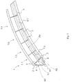
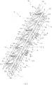
- FIG. 1 Schematic representation of a track element 1 consists of a three-belt system with a first and second belt element as tracks 2 and 3 and a further, i.e. third belt element 4.1, which serves as a tension or compression element depending on the loads that occur.
- the three belt elements 2, 3 and 4.1 are curved and run side by side. In the case of straight stretches, the chord elements even run parallel to one another.
- the two tracks 2 and 3 together with these tracks 2 and 3 connecting trusses 5 form a first bracing level A1.
- the two tracks 2 and 3 are connected to the further belt element 4.1 by means of cross struts 6, with a traverse 5 and two cross struts 6 lying at defined intervals in a plane running transversely to the tracks 2 and 3 and in this way the track element 1 is divided into track sections Split 1.1, 1.2, 1.3, 1.4, etc. form in the process the cross struts 6 connecting the track 3 to the further chord element 4.1 have a second stiffening plane A2 and the cross struts 6 connecting the track 2 to the further chord element 4.1 have a third stiffening plane A3.
- a fourth stiffening level A4 is now formed by means of a stiffening element 7.3 designed as a diagonal strut, which in each case spans a track section (cf. figure 1 , track section 1.1) diagonally spanned.
- a stiffening element 7.3 designed as a diagonal strut, which in each case spans a track section (cf. figure 1 , track section 1.1) diagonally spanned.
- one end of such a diagonal strut 7.3 is connected to a traverse 5 forming the track section 1.1, while its other end is connected in the connection area of the cross struts 6 to the further chord element 4.1, i.e. directly to this further chord element 4.1 or to one of the two cross struts 6.
- this diagonal strut 7.3 is connected centrally to the traverse 5, but it is also possible to connect the diagonal strut 7.3 to the traverse 5 outside the center.
- This fourth reinforcement level A4 not only improves the dynamic load but also the static situation.
- the other chord element 4.1 is loaded as a lower chord in tension and compression depending on the dynamics.
- This stiffening element 7.3 can be designed as any element and can be connected to any connection points provided by the two traverses 5 forming a track section 1.1 to 1.4 with associated cross braces 6 and the further chord element 4.1 in the connection area of these cross struts 6 with this contribution chord element 4.1 will.
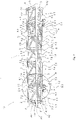
- the track element 1 of Figure 2 corresponds to that of the prior art according to EP 2 156 870 B1 known and in figure 8 shown track element 1, but in accordance with figure 1 in addition, a fourth stiffening level A4 is realized by means of diagonal struts 7.3.
- this track element includes 1 after figure 2 a three-belt system with a first and second belt element 2 and 3 designed as tracks 2 and 3 and with a third or further belt element 4.1 designed as a tension or pressure element.
- the two parallel tracks 2 and 3 are connected to one another via traverses 5 or 5.1 to form the first stiffening level A1 and are each connected to the further chord element 4.1 by means of cross braces 6 or 6.1.
- the track 3 together with the transverse struts 6 and the additional chord element 4.1 forms the second stiffening plane A2 and the track 2 together with the transverse struts 6 and the additional chord element 4.1 forms the third stiffening plane A3.
- the ends of the other belt element 4.1 are formed with flanges 4.11 and 4.12, which are required to connect the track elements 1 to form a track system 10.
- One traverse 5 or 5.1 and two crossbars 6 or 6.1 are arranged in a plane running transversely to the tracks 2 and 3 or the further belt element 4.1, so that track sections 1.1 to 1.7 are produced as a result.
- the traverses 5.1 differ from the traverses 5 in that the traverses 5.1 with the associated transverse struts 6.1 are provided with a prop connection 9 having a prop head 9.1.
- the track elements 1 are connected to vertical supports anchored in the ground, so that the entire track system of such supports is worn. Any support arrangement is also possible, e.g. for a monorail.
- Such a support connection 9 is designed as a surface element with a triangular contour, so that this surface element can be connected to a traverse 5.1 and the associated cross braces 6.1 on the contour side.
- all track sections 1.1 to 1.7 are equipped with diagonal struts 7.1 and 7.2, which are each connected at one end to the traverses 5 or 5.1 and at their other end, diagonally bridging the respective track section, to the further belt element 4.1 and there to the ends of the opposite ones Cross braces 6 form a corner point.
- two diagonal struts 7.1 and 7.2 are provided on both sides, which are connected to the further chord element 4.1 at the ends of the opposite transverse struts 6 of the track section 1.1 and 1.2.
- a corresponding structure can also be seen on the traverse 5.1 of the track sections 1.6 and 1.7.
- Two diagonal struts 7.1 and 7.2 are also connected to the traverses 5 of the adjacent track sections 1.3 and 1.4, the adjacent track sections 1.4 and 1.5 and the adjacent track sections 1.5 and 1.6 and extend diagonally across the respective track section up to the respective opposite cross struts 6 corner point formed with the further belt element 4.1.
- a diagonal strut 7.0 is provided, which diagonally bridges the track sections 1.1 to 1.5 and 1.7.
- This diagonal brace 7.0 connects the corner formed by a traverse 5 or 5.1 with track 2 to the diagonally opposite end of the traverse 5 or 5.1, which forms a corner with track 3.
- the two track sections 1.1 and 1.2 each have a track section 1.1 or 1.2 spanning diagonal strut 7.3 arranged as a stiffening element of the fourth stiffening level A4.
- One end of these two diagonal struts 7.3 is preferably connected centrally to the traverse 5.1 and the other end runs towards the ends of the two diagonal struts 7.1 and 7.2 connected to the further chord element 4.1, where they are also connected to the further chord element 4.1.
- FIG figure 2 Such a structure with a diagonal brace 7.3 as a stiffening element of the fourth stiffening level A4 is shown in FIG figure 2 can also be seen in the adjacent track sections 1.6 and 1.7, where such a diagonal strut 7.3 is connected centrally to the traverse 5.1 connecting these two track sections 1.6 and 1.7 and diagonally bridge these track sections 1.6 and 1.7 towards the further belt element 4.1.
- the track section 1.5 is also in accordance with figure 2 provided with such a diagonal strut 7.3 as a stiffening element of the fourth stiffening level A4, which is also centrally connected to the traverse 5 connecting the two track sections 1.5 and 1.6 and diagonally bridges the track section 1.5 to the further belt element 4.1.
- the track section 1.6 is designed with a first stiffening strut 8.1 and a second stiffening strut 8.2, so that these two stiffening struts 8.1 and 8.2 run in the plane formed by the two tracks 2 and 3.
- the two stiffening struts 8.1 and 8.2 are each connected at one end to the traverse 5.1 and run towards one another in a V-shape, so that they can be connected centrally to the adjacent traverse 5.
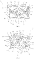
- the figure 5 shows two track elements 1 connected via flanges 4.11 and 4.12, whose track sections 1.6 and 1.7 or 1.1 and 1.2 structurally correspond to the track sections 1.1 and 1.2 according to FIG.
- the two track sections 1.6. and 1.7 connecting traverse 5.1 as well as the associated cross braces 6.1 are formed with a support connection 9 having a support head 9.1.
- Two diagonal struts 7.1 and 7.2 and one diagonal strut 7.3 each are connected to this traverse 5.1 as a stiffening element of the fourth stiffening level A4 and extend diagonally across the track section 1.6 and 1.7 to the end of the opposite transverse struts 6 with the further belt element 4.1 node.
- the track sections 1.1 and 1.2 of the other track section 1 are constructed with a traverse 5.1 connecting them, which has a support base 9 with a support head 9.1; So correspond to those track sections 1.1 and 1.2 of the track element 1 after figure 2
- figure 6 shows two track sections 1.1 and 1.2 connected via flanges 4.1 and 4.2 as a further exemplary embodiment.
- the track section 1.1 of the track element 1 after figure 6 is identical to that track section 1.6 of track element 1 figure 2 constructed and also has two additional stiffening struts 8.1 and 8.2 in addition to the diagonal strut 7.3 as a stiffening element of the fourth stiffening level A4. Furthermore, a first stiffening strut 8.1 and a second stiffening strut 8.2 are also provided on the track section 1.1 forming traverse 5.1 in the direction of the adjacent track section 1.2 in addition to a diagonal strut 7.3 as a stiffening element of the fourth stiffening level A4.
- the adjoining track section 1.3 also has, in addition to the two diagonal struts 7.1 and 7.2, a diagonal strut 7.3 as a stiffening element of the fourth stiffening level A4, but a diagonal strut 7.0 is provided instead of the two stiffening struts 8.1 and 8.2.
- the last two track sections 1.6 and 1.7 of the other track element 1 after figure 6 also have a diagonal strut 7.3 as a stiffening element of the fourth stiffening level A4, with this diagonal strut 7.3 and the two diagonal struts 7.1 and 7.2 being connected to a traverse 5 at the end of the track element 1 or to a traverse 5 connecting the two track sections 1.6 and 1.7.
- first and second stiffening struts 8.1 and 8.2 are each connected to the end of this traverse 5 towards track section 1.6, and likewise a first and second stiffening strut towards track section 1.6 8.1 and 8.2 each connected to the end of this traverse 5.
- these two stiffening struts 8.1 and 8.2 run in each of the two track sections 1.6 and 1.7 in a V-shape in the middle towards the opposite cross member 5.
- the track section 1.7 has a third stiffening strut 8.3, which connects the two trusses 5 in the middle.
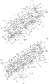
- FIG 7 shows a track element 1 of a track system 10, which is constructed by means of a four-belt system.
- This four-belt system consists of a first and second chord element, which form parallel tracks 2 and 3, and two further chord elements, ie a third and fourth chord element 4.1 and 4.2.
- the two tracks 2 and 3 are spaced apart by means of traverses 5 and, together with them, form a first stiffening level A1.
- the two further chord elements 4.1 and 4.2 are connected to the tracks 2 and 3 via transverse struts 6.2 and further transverse struts 6, forming a stiffening plane A0 parallel to the first stiffening plane A1.
- the two other chord elements 4.1 and 4.2 each form, together with a track 3 or 2 and the associated cross braces 6, a second and third stiffening level A2 and A3.
- the traverses 5, together with the cross braces 6 and 6.2, are spaced apart in planes running transversely to the tracks 2 and 3, so that the track element 1 is thereby divided into track sections 1.1 to 1.6.
- the track sections 1.1 to 1.6 each have diagonal struts 7.0, 7.1, 7.2 and 7.4 arranged in the stiffening planes A1, A2, A3 and A0.
- a diagonal strut 7.3 is in the track section 1.1 as a stiffening element arranged and spanned diagonally this track section 1.1.
- this diagonal strut 7.3 is connected at one end in the middle to a traverse 5 forming the track section 1.1 and is connected to the other end at the opposite connection region of the transverse struts 6 and 6.2 with the further belt element 4.2.
- this diagonal strut 7.3 can be connected directly to the other chord element 4.1 or 4.2 or to a cross strut 6 or 6.2.
- An eccentric connection of the diagonal strut 7.3 to the traverse 5 is also possible.
- such a fourth stiffening level A4 can also be implemented in the other track sections 1.2 to 1.6 by means of a stiffening element 7.3.
- the track sections 1.1 to 1.6 with stiffening struts 8.1, 8.2 and 8.3 arranged in the first stiffening plane A1 can be figure 6 be reinforced.
- the in the Figures 2 to 6 The diagonal struts 7.0, 7.1, 7.2 and 7.3 described and the stiffening struts 8.1, 8.2 and 8.3 are connected in the manner to the traverses 5 or 5.1, the cross struts 6 or 6.1 and to the further chord element 4.1, as explained in the introduction EP 2 156 870 B1 is revealed. Therefore, reference is made to this patent specification in its entirety.
- these diagonal struts 7.0, 7.1, 7.2 and 7.3 can be arranged in such a way that, starting from a traverse 5 or 5.1, they are not routed directly to the further chord element 4.1, but, for example, directly to a support connection 9 or on a cross brace 6 or 6.1 in the area of their connection points to the further belt element 4.1. Furthermore, it is also possible that these diagonal struts 7.0, 7.1 and 7.2 cannot be connected to a traverse 5 or 5.1 but also centrally to a cross strut 6 or 6.1. ...
Landscapes
- Engineering & Computer Science (AREA)
- Transportation (AREA)
- Mechanical Engineering (AREA)
- Rod-Shaped Construction Members (AREA)
- Bridges Or Land Bridges (AREA)
- Train Traffic Observation, Control, And Security (AREA)
- Wind Motors (AREA)
- Transmissions By Endless Flexible Members (AREA)
- Railway Tracks (AREA)
- Joining Of Building Structures In Genera (AREA)
- Bearings For Parts Moving Linearly (AREA)
Applications Claiming Priority (3)
| Application Number | Priority Date | Filing Date | Title |
|---|---|---|---|
| DE102013220067.6A DE102013220067B4 (de) | 2013-10-02 | 2013-10-02 | Gleissystem für ein Fahrgeschäft, insbesondere für eine Achter- oder Hängebahn |
| EP14772386.0A EP3052210B1 (de) | 2013-10-02 | 2014-09-25 | Gleissystem für ein fahrgeschäft, insbesondere für eine achter- oder hängebahn |
| PCT/EP2014/070541 WO2015049162A1 (de) | 2013-10-02 | 2014-09-25 | Gleissystem für ein fahrgeschäft, insbesondere für eine achter- oder hängebahn |
Related Parent Applications (1)
| Application Number | Title | Priority Date | Filing Date |
|---|---|---|---|
| EP14772386.0A Division EP3052210B1 (de) | 2013-10-02 | 2014-09-25 | Gleissystem für ein fahrgeschäft, insbesondere für eine achter- oder hängebahn |
Publications (3)
| Publication Number | Publication Date |
|---|---|
| EP3574968A2 EP3574968A2 (de) | 2019-12-04 |
| EP3574968A3 EP3574968A3 (de) | 2020-02-12 |
| EP3574968B1 true EP3574968B1 (de) | 2022-06-01 |
Family
ID=51619200
Family Applications (2)
| Application Number | Title | Priority Date | Filing Date |
|---|---|---|---|
| EP19181056.3A Active EP3574968B1 (de) | 2013-10-02 | 2014-09-25 | Gleissystem für ein fahrgeschäft, insbesondere für eine achter- oder hängebahn |
| EP14772386.0A Active EP3052210B1 (de) | 2013-10-02 | 2014-09-25 | Gleissystem für ein fahrgeschäft, insbesondere für eine achter- oder hängebahn |
Family Applications After (1)
| Application Number | Title | Priority Date | Filing Date |
|---|---|---|---|
| EP14772386.0A Active EP3052210B1 (de) | 2013-10-02 | 2014-09-25 | Gleissystem für ein fahrgeschäft, insbesondere für eine achter- oder hängebahn |
Country Status (12)
| Country | Link |
|---|---|
| US (1) | US10058788B2 (da) |
| EP (2) | EP3574968B1 (da) |
| JP (1) | JP6280230B2 (da) |
| CN (1) | CN105636657B (da) |
| AU (1) | AU2014331267B2 (da) |
| CA (1) | CA2925044C (da) |
| DE (4) | DE102013220067B4 (da) |
| DK (2) | DK3574968T3 (da) |
| ES (2) | ES2742332T3 (da) |
| HU (2) | HUE059866T2 (da) |
| PL (2) | PL3574968T3 (da) |
| WO (1) | WO2015049162A1 (da) |
Families Citing this family (17)
| Publication number | Priority date | Publication date | Assignee | Title |
|---|---|---|---|---|
| DE102016123928B4 (de) * | 2016-12-09 | 2019-05-29 | Ingenieurbüro Stengel Gmbh | Backboneschiene für eine Achterbahn und Achterbahnanordnung |
| CN107297078A (zh) * | 2017-08-04 | 2017-10-27 | 广州市顺宏游乐设备有限公司 | 一种旋转滑行车 |
| CN107694101A (zh) * | 2017-11-03 | 2018-02-16 | 国汇机械制造泰州有限公司 | 一种疯狂老鼠分段轨道设计 |
| CN107794814B (zh) * | 2017-11-21 | 2023-08-25 | 中铁第四勘察设计院集团有限公司 | 一种悬挂式单轨双线钢轨道梁系统 |
| DE102018108182A1 (de) * | 2018-04-06 | 2019-10-10 | Ingenieurbüro Stengel Gmbh | Fahrrohrstück, Schienenstück, sowie Achterbahnanordnung mit denselben |
| CN108755290A (zh) * | 2018-07-27 | 2018-11-06 | 中国五冶集团有限公司 | 全装配格构式悬挂单轨轨道结构及装配工艺 |
| KR101941409B1 (ko) * | 2018-09-07 | 2019-01-23 | 알엔비이엔씨 주식회사 | 바닥판이 없는 궤도 차량용 트러스 모듈 및 그 시공방법 |
| US11766619B2 (en) | 2019-02-14 | 2023-09-26 | The Gravity Group, LLC | Track for rolling vehicle and methods of fabricating and assembling the track |
| CN110237538B (zh) * | 2019-06-04 | 2020-08-04 | 中建八局第三建设有限公司 | 一种大型过山车安装施工方法 |
| DE102019130956A1 (de) * | 2019-11-15 | 2021-05-20 | Mack Rides Gmbh & Co. Kg | Fahrgeschäft, insbesondere Wasserfahrgeschäft, sowie Verfahren zum Betreiben eines solchen Fahrgeschäfts |
| USD976354S1 (en) * | 2020-03-13 | 2023-01-24 | Ingenieurbuero Stengel Gimbh | Roller coaster track section |
| DE102020118049A1 (de) | 2020-07-08 | 2022-01-13 | Ingenieurbüro Stengel Gmbh | Fachwerkschiene, sowie Achterbahnanordnung mit derselben |
| CN113926205A (zh) * | 2021-11-04 | 2022-01-14 | 广东蕉岭建筑工程集团有限公司 | 一种过山车轨道支撑固定装置 |
| WO2023083479A1 (en) * | 2021-11-15 | 2023-05-19 | Antonio Zamperla S.P.A. | Track segment and track comprising such track segment for an amusement ride |
| KR102493670B1 (ko) * | 2022-06-16 | 2023-01-31 | 이엠티씨 주식회사 | 궤도차량 주행용 레일 장치 |
| US20240091660A1 (en) * | 2022-09-16 | 2024-03-21 | Egor Sovstov | Toy track systems, toy track vehicles, and related methodologies |
| DE102024104836A1 (de) * | 2024-02-21 | 2025-08-21 | Ingenieurbüro Stengel Gmbh | Backboneschiene für eine Achterbahnanordnung und Achterbahnanordnung |
Family Cites Families (11)
| Publication number | Priority date | Publication date | Assignee | Title |
|---|---|---|---|---|
| US629273A (en) | 1896-12-30 | 1899-07-18 | Maschb Actien Ges Nuernberg | Girder structure for suspension-railways. |
| US3949680A (en) * | 1975-01-22 | 1976-04-13 | Doughty Howard E | Vehicle track and vehicle |
| US4489659A (en) | 1979-01-10 | 1984-12-25 | Hitachi, Ltd. | Truss-type girder for supporting a movable body |
| US6047645A (en) | 1998-06-26 | 2000-04-11 | Setpoint Engineered Systems, Inc. | Truss track assembly and side mount roller coaster vehicle |
| KR100389862B1 (ko) | 2000-08-10 | 2003-07-04 | 삼성전자주식회사 | 인쇄기의 배출 용지 적재장치 |
| US20040083922A1 (en) | 2001-04-28 | 2004-05-06 | Gnezdilov Vladimir A. | Guideway for transport means |
| CA2609141C (en) * | 2005-05-20 | 2013-11-26 | William J. Kitchen | Wheel hub rider conveyance |
| EP2156870B1 (de) * | 2008-08-22 | 2011-01-19 | Mack Rides GmbH & Co. KG | Achterbahn mit fachwerkartigen Gleiselementen |
| DE202009008256U1 (de) | 2009-06-16 | 2010-01-07 | Schumacher, Sascha | Schienenelemente |
| FR2951207B1 (fr) * | 2009-10-09 | 2014-07-18 | Spantech France | Poutre treillis repliable, ferme et construction incluant une telle poutre |
| DE202010006408U1 (de) * | 2010-05-04 | 2011-10-12 | Kamal Daas | Gittertragwerk |
-
2013
- 2013-10-02 DE DE102013220067.6A patent/DE102013220067B4/de not_active Expired - Fee Related
-
2014
- 2014-09-25 JP JP2016546158A patent/JP6280230B2/ja active Active
- 2014-09-25 DE DE202014011581.8U patent/DE202014011581U1/de not_active Expired - Lifetime
- 2014-09-25 DE DE202014011342.4U patent/DE202014011342U1/de not_active Expired - Lifetime
- 2014-09-25 HU HUE19181056A patent/HUE059866T2/hu unknown
- 2014-09-25 PL PL19181056.3T patent/PL3574968T3/pl unknown
- 2014-09-25 HU HUE14772386 patent/HUE044711T2/hu unknown
- 2014-09-25 PL PL14772386T patent/PL3052210T3/pl unknown
- 2014-09-25 WO PCT/EP2014/070541 patent/WO2015049162A1/de not_active Ceased
- 2014-09-25 DE DE202014011579.6U patent/DE202014011579U1/de not_active Expired - Lifetime
- 2014-09-25 EP EP19181056.3A patent/EP3574968B1/de active Active
- 2014-09-25 ES ES14772386T patent/ES2742332T3/es active Active
- 2014-09-25 ES ES19181056T patent/ES2927499T3/es active Active
- 2014-09-25 CN CN201480055011.8A patent/CN105636657B/zh active Active
- 2014-09-25 CA CA2925044A patent/CA2925044C/en active Active
- 2014-09-25 EP EP14772386.0A patent/EP3052210B1/de active Active
- 2014-09-25 US US15/023,308 patent/US10058788B2/en active Active
- 2014-09-25 DK DK19181056.3T patent/DK3574968T3/da active
- 2014-09-25 DK DK14772386.0T patent/DK3052210T3/da active
- 2014-09-25 AU AU2014331267A patent/AU2014331267B2/en active Active
Also Published As
| Publication number | Publication date |
|---|---|
| ES2927499T3 (es) | 2022-11-07 |
| PL3574968T3 (pl) | 2022-11-07 |
| DK3052210T3 (da) | 2019-08-26 |
| AU2014331267B2 (en) | 2017-07-27 |
| JP2016537155A (ja) | 2016-12-01 |
| CN105636657B (zh) | 2017-12-29 |
| WO2015049162A1 (de) | 2015-04-09 |
| US20160250560A1 (en) | 2016-09-01 |
| DK3574968T3 (da) | 2022-09-05 |
| EP3052210A1 (de) | 2016-08-10 |
| EP3574968A3 (de) | 2020-02-12 |
| ES2742332T3 (es) | 2020-02-13 |
| DE202014011342U1 (de) | 2019-07-25 |
| HUE044711T2 (hu) | 2019-11-28 |
| DE102013220067A1 (de) | 2015-04-02 |
| DE202014011581U1 (de) | 2022-12-16 |
| DE202014011579U1 (de) | 2022-11-10 |
| CA2925044A1 (en) | 2015-04-09 |
| PL3052210T3 (pl) | 2020-03-31 |
| DE102013220067B4 (de) | 2018-10-11 |
| AU2014331267A1 (en) | 2016-04-14 |
| HK1223585A1 (zh) | 2017-08-04 |
| EP3052210B1 (de) | 2019-06-26 |
| US10058788B2 (en) | 2018-08-28 |
| CA2925044C (en) | 2018-12-04 |
| JP6280230B2 (ja) | 2018-02-14 |
| HUE059866T2 (hu) | 2023-01-28 |
| CN105636657A (zh) | 2016-06-01 |
| EP3574968A2 (de) | 2019-12-04 |
Similar Documents
| Publication | Publication Date | Title |
|---|---|---|
| EP3574968B1 (de) | Gleissystem für ein fahrgeschäft, insbesondere für eine achter- oder hängebahn | |
| DE102016123928B4 (de) | Backboneschiene für eine Achterbahn und Achterbahnanordnung | |
| DE60305328T2 (de) | Förderband | |
| EP2573269B1 (de) | Vorbauschnabel zur Herstellung eines Brückenbauwerks | |
| EP3469143B1 (de) | Pneumatischer träger | |
| DE1530153B2 (de) | Drehgestell fuer eisenbahnfahrzeuge, insbesondere fuer waggons | |
| DE202015001425U1 (de) | Stahlfachwerkschiene | |
| DE2806578A1 (de) | Dreigurttraeger in fachwerkbauweise | |
| DE102013210232A1 (de) | Gitterträger mit bereichsweise gegenläufig geneigten Streben | |
| EP0643169B1 (de) | Einrichtung zum Verbinden von auf einem Tragwerk festgelegten Schienen | |
| DE1658577C3 (de) | Zerlegbare Brücke | |
| DE3222307A1 (de) | Fachwerktraeger | |
| EP2607565A1 (de) | Kederdachfirstträger und Kederdachträgereinrichtung | |
| DE1958294A1 (de) | Seilnetzkonstruktion,insbesondere fuer Daecher u.dgl. | |
| EP4178699B1 (de) | Fachwerkschiene, sowie achterbahnanordnung mit derselben | |
| DE2305714C3 (de) | Holzgitterträger | |
| DE2263729A1 (de) | Rautenfachwerk | |
| DE2140077B2 (da) | ||
| DE102024104836A1 (de) | Backboneschiene für eine Achterbahnanordnung und Achterbahnanordnung | |
| DE1530153C3 (de) | Drehgestell für Eisenbahnfahrzeuge, insbesondere für Waggons | |
| DE2254279A1 (de) | Bauelement, insbesondere fachwerktraeger | |
| DE2052107B2 (de) | Zerlegbare Brücke | |
| DE8033681U1 (de) | Vorrichtung zum abstuetzen von bauelementen, schalungen o.dgl. | |
| DE20207669U1 (de) | Fahrweg für eine Magnetschwebebahn | |
| CH244280A (de) | Fachwerkbrücke und Verfahren zu deren Herstellung. |
Legal Events
| Date | Code | Title | Description |
|---|---|---|---|
| PUAI | Public reference made under article 153(3) epc to a published international application that has entered the european phase |
Free format text: ORIGINAL CODE: 0009012 |
|
| STAA | Information on the status of an ep patent application or granted ep patent |
Free format text: STATUS: REQUEST FOR EXAMINATION WAS MADE |
|
| 17P | Request for examination filed |
Effective date: 20190618 |
|
| AC | Divisional application: reference to earlier application |
Ref document number: 3052210 Country of ref document: EP Kind code of ref document: P |
|
| AK | Designated contracting states |
Kind code of ref document: A2 Designated state(s): AL AT BE BG CH CY CZ DE DK EE ES FI FR GB GR HR HU IE IS IT LI LT LU LV MC MK MT NL NO PL PT RO RS SE SI SK SM TR |
|
| PUAL | Search report despatched |
Free format text: ORIGINAL CODE: 0009013 |
|
| AK | Designated contracting states |
Kind code of ref document: A3 Designated state(s): AL AT BE BG CH CY CZ DE DK EE ES FI FR GB GR HR HU IE IS IT LI LT LU LV MC MK MT NL NO PL PT RO RS SE SI SK SM TR |
|
| RIC1 | Information provided on ipc code assigned before grant |
Ipc: A63G 7/00 20060101AFI20200107BHEP |
|
| STAA | Information on the status of an ep patent application or granted ep patent |
Free format text: STATUS: EXAMINATION IS IN PROGRESS |
|
| 17Q | First examination report despatched |
Effective date: 20210420 |
|
| GRAP | Despatch of communication of intention to grant a patent |
Free format text: ORIGINAL CODE: EPIDOSNIGR1 |
|
| STAA | Information on the status of an ep patent application or granted ep patent |
Free format text: STATUS: GRANT OF PATENT IS INTENDED |
|
| INTG | Intention to grant announced |
Effective date: 20220210 |
|
| GRAS | Grant fee paid |
Free format text: ORIGINAL CODE: EPIDOSNIGR3 |
|
| GRAA | (expected) grant |
Free format text: ORIGINAL CODE: 0009210 |
|
| STAA | Information on the status of an ep patent application or granted ep patent |
Free format text: STATUS: THE PATENT HAS BEEN GRANTED |
|
| AC | Divisional application: reference to earlier application |
Ref document number: 3052210 Country of ref document: EP Kind code of ref document: P |
|
| AK | Designated contracting states |
Kind code of ref document: B1 Designated state(s): AL AT BE BG CH CY CZ DE DK EE ES FI FR GB GR HR HU IE IS IT LI LT LU LV MC MK MT NL NO PL PT RO RS SE SI SK SM TR |
|
| REG | Reference to a national code |
Ref country code: GB Ref legal event code: FG4D Free format text: NOT ENGLISH |
|
| REG | Reference to a national code |
Ref country code: AT Ref legal event code: REF Ref document number: 1494975 Country of ref document: AT Kind code of ref document: T Effective date: 20220615 Ref country code: CH Ref legal event code: EP Ref country code: DE Ref legal event code: R096 Ref document number: 502014016270 Country of ref document: DE |
|
| REG | Reference to a national code |
Ref country code: IE Ref legal event code: FG4D Free format text: LANGUAGE OF EP DOCUMENT: GERMAN |
|
| REG | Reference to a national code |
Ref country code: RO Ref legal event code: EPE |
|
| REG | Reference to a national code |
Ref country code: DK Ref legal event code: T3 Effective date: 20220901 |
|
| REG | Reference to a national code |
Ref country code: NL Ref legal event code: FP |
|
| REG | Reference to a national code |
Ref country code: LT Ref legal event code: MG9D |
|
| REG | Reference to a national code |
Ref country code: SE Ref legal event code: TRGR |
|
| RAP2 | Party data changed (patent owner data changed or rights of a patent transferred) |
Owner name: MACK RIDES IP GMBH & CO. KG |
|
| REG | Reference to a national code |
Ref country code: DE Ref legal event code: R081 Ref document number: 502014016270 Country of ref document: DE Owner name: MACK RIDES IP GMBH & CO. KG, DE Free format text: FORMER OWNER: MACK RIDES GMBH & CO. KG, 79183 WALDKIRCH, DE |
|
| PG25 | Lapsed in a contracting state [announced via postgrant information from national office to epo] |
Ref country code: NO Free format text: LAPSE BECAUSE OF FAILURE TO SUBMIT A TRANSLATION OF THE DESCRIPTION OR TO PAY THE FEE WITHIN THE PRESCRIBED TIME-LIMIT Effective date: 20220901 Ref country code: LT Free format text: LAPSE BECAUSE OF FAILURE TO SUBMIT A TRANSLATION OF THE DESCRIPTION OR TO PAY THE FEE WITHIN THE PRESCRIBED TIME-LIMIT Effective date: 20220601 Ref country code: HR Free format text: LAPSE BECAUSE OF FAILURE TO SUBMIT A TRANSLATION OF THE DESCRIPTION OR TO PAY THE FEE WITHIN THE PRESCRIBED TIME-LIMIT Effective date: 20220601 Ref country code: GR Free format text: LAPSE BECAUSE OF FAILURE TO SUBMIT A TRANSLATION OF THE DESCRIPTION OR TO PAY THE FEE WITHIN THE PRESCRIBED TIME-LIMIT Effective date: 20220902 Ref country code: FI Free format text: LAPSE BECAUSE OF FAILURE TO SUBMIT A TRANSLATION OF THE DESCRIPTION OR TO PAY THE FEE WITHIN THE PRESCRIBED TIME-LIMIT Effective date: 20220601 Ref country code: BG Free format text: LAPSE BECAUSE OF FAILURE TO SUBMIT A TRANSLATION OF THE DESCRIPTION OR TO PAY THE FEE WITHIN THE PRESCRIBED TIME-LIMIT Effective date: 20220901 |
|
| REG | Reference to a national code |
Ref country code: ES Ref legal event code: FG2A Ref document number: 2927499 Country of ref document: ES Kind code of ref document: T3 Effective date: 20221107 |
|
| PG25 | Lapsed in a contracting state [announced via postgrant information from national office to epo] |
Ref country code: RS Free format text: LAPSE BECAUSE OF FAILURE TO SUBMIT A TRANSLATION OF THE DESCRIPTION OR TO PAY THE FEE WITHIN THE PRESCRIBED TIME-LIMIT Effective date: 20220601 Ref country code: LV Free format text: LAPSE BECAUSE OF FAILURE TO SUBMIT A TRANSLATION OF THE DESCRIPTION OR TO PAY THE FEE WITHIN THE PRESCRIBED TIME-LIMIT Effective date: 20220601 |
|
| REG | Reference to a national code |
Ref country code: HU Ref legal event code: AG4A Ref document number: E059866 Country of ref document: HU |
|
| PG25 | Lapsed in a contracting state [announced via postgrant information from national office to epo] |
Ref country code: SM Free format text: LAPSE BECAUSE OF FAILURE TO SUBMIT A TRANSLATION OF THE DESCRIPTION OR TO PAY THE FEE WITHIN THE PRESCRIBED TIME-LIMIT Effective date: 20220601 Ref country code: SK Free format text: LAPSE BECAUSE OF FAILURE TO SUBMIT A TRANSLATION OF THE DESCRIPTION OR TO PAY THE FEE WITHIN THE PRESCRIBED TIME-LIMIT Effective date: 20220601 Ref country code: PT Free format text: LAPSE BECAUSE OF FAILURE TO SUBMIT A TRANSLATION OF THE DESCRIPTION OR TO PAY THE FEE WITHIN THE PRESCRIBED TIME-LIMIT Effective date: 20221003 Ref country code: EE Free format text: LAPSE BECAUSE OF FAILURE TO SUBMIT A TRANSLATION OF THE DESCRIPTION OR TO PAY THE FEE WITHIN THE PRESCRIBED TIME-LIMIT Effective date: 20220601 |
|
| PG25 | Lapsed in a contracting state [announced via postgrant information from national office to epo] |
Ref country code: IS Free format text: LAPSE BECAUSE OF FAILURE TO SUBMIT A TRANSLATION OF THE DESCRIPTION OR TO PAY THE FEE WITHIN THE PRESCRIBED TIME-LIMIT Effective date: 20221001 |
|
| REG | Reference to a national code |
Ref country code: DE Ref legal event code: R097 Ref document number: 502014016270 Country of ref document: DE |
|
| PG25 | Lapsed in a contracting state [announced via postgrant information from national office to epo] |
Ref country code: AL Free format text: LAPSE BECAUSE OF FAILURE TO SUBMIT A TRANSLATION OF THE DESCRIPTION OR TO PAY THE FEE WITHIN THE PRESCRIBED TIME-LIMIT Effective date: 20220601 |
|
| PLBE | No opposition filed within time limit |
Free format text: ORIGINAL CODE: 0009261 |
|
| STAA | Information on the status of an ep patent application or granted ep patent |
Free format text: STATUS: NO OPPOSITION FILED WITHIN TIME LIMIT |
|
| PG25 | Lapsed in a contracting state [announced via postgrant information from national office to epo] |
Ref country code: MC Free format text: LAPSE BECAUSE OF FAILURE TO SUBMIT A TRANSLATION OF THE DESCRIPTION OR TO PAY THE FEE WITHIN THE PRESCRIBED TIME-LIMIT Effective date: 20220601 |
|
| 26N | No opposition filed |
Effective date: 20230302 |
|
| PG25 | Lapsed in a contracting state [announced via postgrant information from national office to epo] |
Ref country code: SI Free format text: LAPSE BECAUSE OF FAILURE TO SUBMIT A TRANSLATION OF THE DESCRIPTION OR TO PAY THE FEE WITHIN THE PRESCRIBED TIME-LIMIT Effective date: 20220601 |
|
| P01 | Opt-out of the competence of the unified patent court (upc) registered |
Effective date: 20230427 |
|
| PG25 | Lapsed in a contracting state [announced via postgrant information from national office to epo] |
Ref country code: LU Free format text: LAPSE BECAUSE OF NON-PAYMENT OF DUE FEES Effective date: 20220925 |
|
| PG25 | Lapsed in a contracting state [announced via postgrant information from national office to epo] |
Ref country code: IE Free format text: LAPSE BECAUSE OF NON-PAYMENT OF DUE FEES Effective date: 20220925 |
|
| PGFP | Annual fee paid to national office [announced via postgrant information from national office to epo] |
Ref country code: RO Payment date: 20230913 Year of fee payment: 10 |
|
| PGFP | Annual fee paid to national office [announced via postgrant information from national office to epo] |
Ref country code: HU Payment date: 20230924 Year of fee payment: 10 |
|
| PG25 | Lapsed in a contracting state [announced via postgrant information from national office to epo] |
Ref country code: CY Free format text: LAPSE BECAUSE OF FAILURE TO SUBMIT A TRANSLATION OF THE DESCRIPTION OR TO PAY THE FEE WITHIN THE PRESCRIBED TIME-LIMIT Effective date: 20220601 |
|
| PG25 | Lapsed in a contracting state [announced via postgrant information from national office to epo] |
Ref country code: MK Free format text: LAPSE BECAUSE OF FAILURE TO SUBMIT A TRANSLATION OF THE DESCRIPTION OR TO PAY THE FEE WITHIN THE PRESCRIBED TIME-LIMIT Effective date: 20220601 |
|
| PG25 | Lapsed in a contracting state [announced via postgrant information from national office to epo] |
Ref country code: MT Free format text: LAPSE BECAUSE OF FAILURE TO SUBMIT A TRANSLATION OF THE DESCRIPTION OR TO PAY THE FEE WITHIN THE PRESCRIBED TIME-LIMIT Effective date: 20220601 |
|
| PG25 | Lapsed in a contracting state [announced via postgrant information from national office to epo] |
Ref country code: BG Free format text: LAPSE BECAUSE OF FAILURE TO SUBMIT A TRANSLATION OF THE DESCRIPTION OR TO PAY THE FEE WITHIN THE PRESCRIBED TIME-LIMIT Effective date: 20220601 |
|
| PG25 | Lapsed in a contracting state [announced via postgrant information from national office to epo] |
Ref country code: BG Free format text: LAPSE BECAUSE OF FAILURE TO SUBMIT A TRANSLATION OF THE DESCRIPTION OR TO PAY THE FEE WITHIN THE PRESCRIBED TIME-LIMIT Effective date: 20220601 |
|
| PG25 | Lapsed in a contracting state [announced via postgrant information from national office to epo] |
Ref country code: HU Free format text: LAPSE BECAUSE OF NON-PAYMENT OF DUE FEES Effective date: 20240926 |
|
| PG25 | Lapsed in a contracting state [announced via postgrant information from national office to epo] |
Ref country code: RO Free format text: LAPSE BECAUSE OF NON-PAYMENT OF DUE FEES Effective date: 20240925 |
|
| REG | Reference to a national code |
Ref country code: CH Ref legal event code: U11 Free format text: ST27 STATUS EVENT CODE: U-0-0-U10-U11 (AS PROVIDED BY THE NATIONAL OFFICE) Effective date: 20251001 |
|
| PGFP | Annual fee paid to national office [announced via postgrant information from national office to epo] |
Ref country code: DK Payment date: 20250922 Year of fee payment: 12 |
|
| PGFP | Annual fee paid to national office [announced via postgrant information from national office to epo] |
Ref country code: PL Payment date: 20250818 Year of fee payment: 12 Ref country code: NL Payment date: 20250922 Year of fee payment: 12 |
|
| PGFP | Annual fee paid to national office [announced via postgrant information from national office to epo] |
Ref country code: BE Payment date: 20250919 Year of fee payment: 12 Ref country code: GB Payment date: 20250923 Year of fee payment: 12 |
|
| PGFP | Annual fee paid to national office [announced via postgrant information from national office to epo] |
Ref country code: FR Payment date: 20250926 Year of fee payment: 12 Ref country code: AT Payment date: 20250918 Year of fee payment: 12 |
|
| PGFP | Annual fee paid to national office [announced via postgrant information from national office to epo] |
Ref country code: SE Payment date: 20250922 Year of fee payment: 12 |
|
| PGFP | Annual fee paid to national office [announced via postgrant information from national office to epo] |
Ref country code: CZ Payment date: 20250912 Year of fee payment: 12 |
|
| PG25 | Lapsed in a contracting state [announced via postgrant information from national office to epo] |
Ref country code: TR Free format text: LAPSE BECAUSE OF FAILURE TO SUBMIT A TRANSLATION OF THE DESCRIPTION OR TO PAY THE FEE WITHIN THE PRESCRIBED TIME-LIMIT Effective date: 20220601 |
|
| PGFP | Annual fee paid to national office [announced via postgrant information from national office to epo] |
Ref country code: DE Payment date: 20251028 Year of fee payment: 12 |
|
| PGFP | Annual fee paid to national office [announced via postgrant information from national office to epo] |
Ref country code: IT Payment date: 20250930 Year of fee payment: 12 |
|
| PGFP | Annual fee paid to national office [announced via postgrant information from national office to epo] |
Ref country code: CH Payment date: 20251001 Year of fee payment: 12 |
|
| PGFP | Annual fee paid to national office [announced via postgrant information from national office to epo] |
Ref country code: ES Payment date: 20251020 Year of fee payment: 12 |