EP3575011A1 - Machine de laminage pour former une partie filetée sur un corps cylindrique - Google Patents
Machine de laminage pour former une partie filetée sur un corps cylindrique Download PDFInfo
- Publication number
- EP3575011A1 EP3575011A1 EP19174522.3A EP19174522A EP3575011A1 EP 3575011 A1 EP3575011 A1 EP 3575011A1 EP 19174522 A EP19174522 A EP 19174522A EP 3575011 A1 EP3575011 A1 EP 3575011A1
- Authority
- EP
- European Patent Office
- Prior art keywords
- respect
- mandrel
- support group
- holder plate
- axis
- Prior art date
- Legal status (The legal status is an assumption and is not a legal conclusion. Google has not performed a legal analysis and makes no representation as to the accuracy of the status listed.)
- Withdrawn
Links
- 238000005096 rolling process Methods 0.000 title claims abstract description 28
- 230000033001 locomotion Effects 0.000 claims description 23
- 230000006835 compression Effects 0.000 description 4
- 238000007906 compression Methods 0.000 description 4
- 230000009471 action Effects 0.000 description 3
- 230000005540 biological transmission Effects 0.000 description 3
- 230000005415 magnetization Effects 0.000 description 3
- 238000000034 method Methods 0.000 description 3
- 238000004804 winding Methods 0.000 description 3
- 229910000831 Steel Inorganic materials 0.000 description 2
- 230000008878 coupling Effects 0.000 description 2
- 238000010168 coupling process Methods 0.000 description 2
- 238000005859 coupling reaction Methods 0.000 description 2
- 238000005520 cutting process Methods 0.000 description 2
- 238000006073 displacement reaction Methods 0.000 description 2
- 239000000696 magnetic material Substances 0.000 description 2
- 230000014759 maintenance of location Effects 0.000 description 2
- 239000000463 material Substances 0.000 description 2
- 230000002093 peripheral effect Effects 0.000 description 2
- 230000008569 process Effects 0.000 description 2
- 230000001681 protective effect Effects 0.000 description 2
- 238000000926 separation method Methods 0.000 description 2
- 239000010959 steel Substances 0.000 description 2
- 238000011282 treatment Methods 0.000 description 2
- 238000005265 energy consumption Methods 0.000 description 1
- 238000005242 forging Methods 0.000 description 1
- 238000010438 heat treatment Methods 0.000 description 1
- 238000004519 manufacturing process Methods 0.000 description 1
- 239000002184 metal Substances 0.000 description 1
- 238000003801 milling Methods 0.000 description 1
- 230000000750 progressive effect Effects 0.000 description 1
- 238000003892 spreading Methods 0.000 description 1
- 230000007480 spreading Effects 0.000 description 1
- 230000003068 static effect Effects 0.000 description 1
Images







Classifications
-
- B—PERFORMING OPERATIONS; TRANSPORTING
- B21—MECHANICAL METAL-WORKING WITHOUT ESSENTIALLY REMOVING MATERIAL; PUNCHING METAL
- B21H—MAKING PARTICULAR METAL OBJECTS BY ROLLING, e.g. SCREWS, WHEELS, RINGS, BARRELS, BALLS
- B21H3/00—Making helical bodies or bodies having parts of helical shape
- B21H3/02—Making helical bodies or bodies having parts of helical shape external screw-threads ; Making dies for thread rolling
- B21H3/04—Making by means of profiled-rolls or die rolls
Definitions
- the present invention regards a rolling machine for forming a threaded portion on a cylindrical body, according to the preamble of the main independent claim.
- the present rolling machine is included in the industrial field of precision mechanical processing obtained by means of cold plastic deformation and capable of conferring to the processed metallic components high mechanical performance and in particular tenacity and fatigue strength.
- the machine and the method, object of the invention are advantageously intended to be employed for forming threaded portions on metallic cylindrical bodies such as shafts, bars, rods etc.
- Rolling machines provided with a load-bearing structure are currently available on the market.
- two or more operating heads are mounted, each associated with a corresponding forming roller peripherally having a first threaded portion obtained thereon, in order to make an impression, i.e. a corresponding second threaded portion, on the cylindrical body to be formed.
- the surface processing of the single forming rollers cooperate with each other in succession in order to plastically deform the surface of the cylindrical body to be processed placed along a central work axis of the machine and in order to form the profile of the desired threaded portion thereon. Therefore, the impression left by the forming rollers forms the final threaded portion desired for the cylindrical body and in particular, as is known, the threaded portion is substantially constituted by a helical groove made on the external cylindrical wall of the cylindrical body to be processed.
- cylindrical body provided with the aforesaid desired final threaded portion is susceptible of being coupled by means of shape coupling with a screw internally provided with a corresponding threaded portion.
- cylindrical body it will be indicated the mechanical piece/part or member to be formed, whether it is a shaft, a bar, a rod or another cylindrical metallic body on which it is desired to form the impression by means of cold plastic deformation.
- the forming by means of rolling machine with cold plastic deformation allows producing cylindrical bodies provided with threaded portion that mechanically are particularly strong.
- the metallic crystalline chains, for example made of steel, of the body to be processed with the deformation are not cut, as instead occurs in a conventional milling process, but progressively deformed up to obtaining the necessary impression.
- the rolling machine confers, during the particular cold processing, forging properties to the processed cylindrical body which increase the fatigue strength of the metal with which the cylindrical body to be processed is made as well as increase the static load at the base of the thread. It is known that the mechanical strength of a threaded portion made by means of a rolling machine is on the order of 30% greater than that made with a normal cutting process.
- each forming roller is mounted on a tool-holder shaft, which is actuated to rotate by a corresponding motor.
- each forming roller, mounted on the relative operating head is driven by a corresponding linear actuator to move along a transversal axis substantially perpendicular to the work axis, in order to impart, by means of compression, with its threaded portion, an impression on the metallic body to be formed.
- each forming roller during the forming step progressively advances towards the cylindrical body in order to embed its threaded portion on the external surface of the cylindrical body itself; in this manner, part of the material of the cylindrical body is moved onto the external surface thereof in order to leave space for the impression defining the threaded portion.
- the forming operations are controlled by means of a logic control unit, for example of the numerical control type, managed by an external computer (CNC).
- a logic control unit for example of the numerical control type, managed by an external computer (CNC).
- each operating head comprises a support group integral with the movable stem of the linear actuator and a mandrel-holder plate, which supports the corresponding forming roller and is mechanically connected to the support group by means of a substantially horizontal rotation pin.
- first fixing means for removably locking the mandrel-holder plate to the support group in the selected angular position.
- the adjustment of the angle between the work axis and hence the axis of the cylindrical body to be formed and the axis of the forming rollers has the object of allowing varying the component of the drag force of the cylindrical body along the work axis exerted by the forming rollers.
- the support group is formed by a driving body fixed to the stem of the linear actuator, and by a sliding body on which the forming roller is mounted.
- the sliding body is actuatable to slide on the driving body by rotating around a vertical axis.
- second fixing means for removably locking the sliding body with respect to the driving body in the selected angular position.
- the adjustment of the angle of the slide and hence of the forming roller around a vertical axis instead has the object of varying the cutting action of the first rings of threaded portion of the forming roller on the cylindrical body to be processed.
- the forming roller starts its action with the first revolutions of threading in a less incisive manner in order to preserve such first rings of threaded portion. This is obtained by slightly spreading, for example, the axis of the forming rollers in order to create an introduction for the entering of the cylindrical body to be formed.
- the main drawback lies in the fact that the first fixing means currently employed for locking the mandrel-holder plate to the support group, in the selected angular position, are generally manual and this makes the adjustment operations of the dragging of the cylindrical bodies to be formed particularly long and complex each time the production is changed. Solutions with oil-pressure retention jacks are hard to make, since difficult hydraulic seals must be made on the support group, in turn provided with adjustments and hence moving parts.
- a further drawback lies in the fact that in current rolling machines of the above-described type, the angular adjustment along a vertical axis of the position of the sliding body (and hence of the forming roller) with respect to the driving body entails the separation between the relative slide surfaces in contact, when in order to carry out the adjustment the second fixing means are loosened.
- the weight of the sliding body, supporting the forming roller projectingly on the driving body determines the separation of the slide surfaces in contact and, as stated, adjustment difficulties.
- the problem underlying the present invention is therefore to overcome the drawbacks manifested by the abovementioned solutions of known type by providing a rolling machine for forming a threaded portion on a cylindrical body, which allows maintaining the components of the operating heads, which through the forming rollers form the threaded portion on the cylindrical body to be processed, firmly assembled together even during the compression stresses of the rollers caused against the cylindrical body to be formed.
- a further object of the present invention is to provide a rolling machine for forming a threaded portion on a cylindrical body, which allows easily and safely adjusting the angular position of each forming roller with respect to a horizontal rotation axis that is transversal to the axis of the forming roller for advancing towards the cylindrical body to be formed.
- a further object of the present invention is to provide a rolling machine for forming a threaded portion on a cylindrical body, which allows easily and safely adjusting the angular position of each forming roller with respect to a vertical rotation axis that is transversal to the axis of the forming roller for advancing towards the cylindrical body to be formed.
- a further object of the present invention is to provide a rolling machine which is simple and inexpensive to make.
- reference number 1 overall indicates a rolling machine for forming threaded portions on cylindrical bodies in accordance with the present invention.
- This is generally intended to be employed for making threading treatments or other impressions on cylindrical bodies of mechanical members such as shafts, bars, rods etc. for many different applications.
- the aforesaid treatments are obtained, in a per se known and conventional manner, by means of cold plastic deformation of the surface of the cylindrical body to be formed, by compressing it between multiple forming rollers placed peripherally with respect to the cylindrical body itself.
- cylindrical body will refer to the mechanical piece or member on which it is desired to make a threading processing, such as a shaft, a bar, a rod or still another cylindrical member.
- the threaded portions are obtained, in a per se known and conventional manner, by means of cold plastic deformation of the surface of the cylindrical body to be formed by compressing the same cylindrical body between multiple forming rollers 6 placed peripherally with respect to the cylindrical body itself, which is therefore centered with respect to the forming rollers.
- the rolling machine 1 is provided with a load-bearing structure 2 intended to be set on the ground, with which at least two operating heads 60 are mechanically associated.
- the operating heads have corresponding aforesaid forming rollers 6 mechanically associated thereto.
- rollers act with their threaded portion against the lateral surface of the cylindrical body to be formed, being actuated to work by rotating, in a first approximation around axes parallel to each other, in a common rotation direction, and in compression on the same lateral surface of the cylindrical body to be formed.
- the load-bearing structure 2 is obtained by means of a metallic framework between a front part, from which the supplying of the cylindrical body to be formed occurs, and a rear part in which the motorizations of the forming rollers 6 are generally provided for. Between such front and rear parts, a central work axis A is thus identifiable at which the cylindrical body C to be formed is substantially coaxially arrangeable.
- the load-bearing structure 2 extends longitudinally between a front wall 3 and a rear wall 4, each advantageously provided with a central opening 5 for the passage of the cylindrical body to be processed.
- the central work axis A is arranged orthogonally to the front wall 3 and to the rear wall and passes through the center of the aforesaid openings 5, which are then crossed by the cylindrical body to be processed.
- Each of the two forming rollers 6 is actuatable to rotate around the rotation axis Z thereof and is peripherally provided with a first threaded portion 8 having at least one first thread extending around the rotation axis Z.
- the forming rollers 6 are susceptible of plastically deforming the cylindrical body C that can be arranged along a central work axis A of the machine 1 interposed between the forming rollers 6, in order to form on the cylindrical body C a second threaded portion provided with at least one second thread that is substantially counter-shaped with respect to the first thread of the forming rollers 6.
- Each forming roller 6 is constituted, in a per se conventional manner, by a cylindrical body C, preferably made of steel, provided with a central symmetry axis that corresponds to the rotation axis Z thereof, and that is peripherally provided with the first threaded portion 8 formed by at least one first thread.
- the first threaded portion 8 of each forming roller 6 can be constituted by a single thread or by multiple side-by-side and parallel threads. With the term threaded portion it is thus intended a thread if single or the set of multiple threads that extend on the external lateral surface of the forming rollers 6. Only for the sake of description simplicity, hereinbelow the threaded portion will be considered consisting of a single thread such that such terms coincide as well as the reference number "8"; nevertheless, of course, the first threaded portion 8 can also be consisting of multiple threads without departing from the protective scope of the present patent.
- Each thread 8 extends without interruption with a spiral shape, which develops by winding on the external surface of the forming roller 6, advancing along the longitudinal extension and rotation axis Z thereof.
- Each thread 8 appears consisting of, in a longitudinal reading direction parallel to the axis Z thereof, a succession of profiles 12 (with particular reference to the attached figure 13 ) which of course are circumferentially connected to each other without interruption to form a single thread 8 wound as a spiral.
- the thread 8 has a transversal section with respect to its spiral extension that is for example approximately triangular or trapezoidal shaped with external crests 24 tapered with respect to an enlarged base. At the crests 24, the radius of the forming roller 6 is maximum, while at the troughs 10, which are alternated with the crests 24, the radius of the forming rollers 6 is minimum.
- the crests 24 and the troughs 10 are connected by tilted flanks 32.
- the pitch P of the threaded portion remains defined by the axial distance between two crests 24 in succession while the radial distance between the crests 24 and the troughs 10 defines the depth L of the threaded portion 8.
- the thread 8 therefore extends on the external peripheral surface of the roller 6 and around the rotation axis Z with a helical extension and with shape and pitch characteristics that vary in accordance with the application needs of the cylindrical body to be formed.
- the machine 1 provides for two forming rollers 6, placed at 180 degrees from each other.
- the machine can of course provide for a different number of forming rollers 6, in particular three forming rollers 6 arranged at 120 degrees from each other, without departing from the protective scope of the present patent.
- the forming rollers 6 are suitable to plastically deform under cold conditions the cylindrical body to be formed positioned along the central work axis A of the machine and supported in such position, in order to form a second threaded portion provided with at least one second thread substantially counter-shaped with respect to the first thread of said forming rollers 6.
- the machine 1 also comprises two or more linear actuators 7 mounted on the load-bearing structure 2, each mechanically connected to a corresponding forming roller 6 of the operating head 60 in order to move it along a respective first transversal axis R substantially perpendicular to the work axis A.
- the linear actuators 7 actuate the forming rollers 6 to translate along the first transversal axes R moving towards and away from the central work axis A and consequently towards and away from the cylindrical body to be formed.
- the forming rollers 6 are positioned around the central work axis A with their extension axes Z in first approximation substantially parallel to the central work axis A and at an adjustable radial distance due to the actuation of the linear actuators 7. More precisely, the axes Z of the forming rollers 6 are slightly tilted with respect to each other in order to determine the advancement of the cylindrical body to be processed.
- the linear actuators 7 are obtained with hydraulic actuators, in particular hydraulic pistons, that are oriented with the displacement axis aligned with the first transversal movement axis R of the corresponding forming roller 6 and passing through the work axis A.
- Each hydraulic actuator of the linear actuators 7 is advantageously provided with a hollow cylindrical body fixed to the front wall 3 of the load-bearing structure 2 of the machine 1.
- a piston is slidably mounted along the first transversal axis R.
- Such piston is provided with a movable stem 9, which mechanically supports the corresponding operating head 60.
- the hydraulic actuator 7 is connected to a pressurized oil hydraulic plant capable of moving the stem 9 and the forming roller 6 supported thereby along such first transversal axis R as well as capable of placing the forming roller 6 under pressure with an adjustable force against the external surface of the cylindrical body to be formed.
- a pressurized oil hydraulic plant capable of moving the stem 9 and the forming roller 6 supported thereby along such first transversal axis R as well as capable of placing the forming roller 6 under pressure with an adjustable force against the external surface of the cylindrical body to be formed.
- the mechanical connection between the forming rollers 6 and the linear actuators 7 occurs through mechanical members that allow at least two adjustments, as described in detail hereinbelow.
- motor means which are prearranged on the load-bearing structure 2 in the rear part of the machine 1 (of per se known type and not illustrated in the attached figures), mechanically connected to the forming rollers 6 in order to drive them in rotation in abutment against the cylindrical body to be formed, so as to impart the aforesaid cold plastic deformation on the external surface thereof.
- the forming rollers 6 have a seat, e.g. a through hole made along the longitudinal extension axis Z thereof, in which is inserted in a coupling relationship a tool-holder shaft 29, connected by means of a transmission to the motor means.
- a seat e.g. a through hole made along the longitudinal extension axis Z thereof, in which is inserted in a coupling relationship a tool-holder shaft 29, connected by means of a transmission to the motor means.
- the latter are for example obtained with electric motors, in particular of brushless type, each associated to a corresponding forming roller 6, and provided with a drive shaft connected to the tool-holder shaft by means of a cardan joint transmission 27, in accordance with the particular embodiment illustrated in the attached figures.
- the motor means and in particular the brushless motors, are capable of precisely controlling the rotation speed of the shafts thereof and their angular position (and hence of the forming roller that they drive in rotation) with respect to an angular reference position.
- the cardan joints 27 interposed between the drive shafts and the tool-holder shafts 29 allow the transmission of the rotation without having to align the drive shafts with the axes of the forming rollers 6, which can therefore rotate at different distances from the central work axis A and they can also have a tilt with respect to the rotation axes of the drive shafts.
- two forming rollers 6 are provided for that are arranged at 180° from each other with respect to the work axis A in a manner such to equally distribute the stresses on the cylindrical body to be formed.
- the rolling machine 1, object of the present invention also comprises a support base 14 mechanically connected to the load-bearing structure 2, that is substantially interposed between the forming rollers 6 and it is intended to mechanically support the cylindrical body for its plastic deformation.
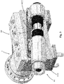
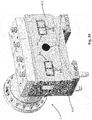
- the operating head 60 comprises a support group 61, integral with the movable stem 9 of the linear actuator 7, and a mandrel-holder plate 62, which supports the corresponding forming roller 6 and it is mechanically connected to the support group 61.
- the rotation pin 63 allows the mandrel-holder plate 62 and hence the forming roller 6 to rotate around a first substantially horizontal axis O, perpendicular to the work axis A, and preferably substantially coinciding with the first transversal movement axis R of the forming roller 6 (the two axes R and O are in any case tiltable with the adjustment described hereinbelow), in order to allow a first angular rotation of the forming roller 6 itself with respect to such first horizontal axis O and thus allow tilting the axis of the forming roller 6 with respect to the central work axis A.
- the first fixing means 64 are instead susceptible of rigidly locking the mandrel-holder plate 62 to the support group 61 in the selected angular position.
- the rolling machine 1 provides for that the aforesaid first fixing means 64 comprise first magnetic means actuatable to lock and release the mandrel-holder plate 62 with respect to the support group 61.
- the present invention it is thus possible to deactivate the aforesaid first magnetic means 64 in order to adjust the angle of the forming roller 6 by rotating the mandrel-holder plate 62 which supports it around the rotation pin 63, i.e. around the first horizontal axis O, and with respect to the support group 61 integral with the stem 9 of the linear actuator 7 so as to vary the angle of the axis of the forming roller 6 with respect to the central work axis A of the machine (and hence with respect to the axis of the cylindrical body C to be formed), and hence reactivate the aforesaid first magnetic means 64 in order to lock the mandrel-holder plate 62, and thus the forming roller 6, in the desired angular position.
- the aforesaid first magnetic means 64 comprise two or more electropermanent magnets 640 mounted on the mandrel-holder plate 62 or on the support group 61 and actuatable to be activated and deactivated by an electrical pulse.
- an electropermanent magnet also known with the initials EPM, is a type of permanent magnet in which the external magnetic field can be activated or deactivated by a pulse of electric current in a wire winding around a part of the magnet.
- the magnet consists of two parts, one of "hard” magnetic material (high coerciveness) and one of "soft” magnetic material (low coerciveness).
- the direction of the magnetization of the magnet with low coerciveness can be switched by a current pulse in a winding of the wire that encloses it.
- the electropermanent magnet does not produce any net/clear external field through its poles, while when their magnetization direction is aligned, the electropermanent magnet produces an external magnetic field.
- electropermanent magnets is preferable in the present invention, with respect to the use of electromagnets, in particular due to safety in case of interruption of current supply, as well as for a reduced energy consumption and for the absence of heating of the components.
- the first magnetic means 64 can also be constituted by electromagnets.
- the logic control unit of the machine will be susceptible of deactivating at least one first electropermanent magnet, leaving at least one second electropermanent magnet activated in order to allow the first movement means 13 to move the mandrel-holder plate 62 with respect to the support group 61, overcoming the magnetic attraction of the second electropermanent magnet.
- the machine according to the invention also comprises first movement means 13 acting on the mandrel-holder plate 62 in order to drive it in rotation around the pin 63.
- first movement means 13 comprise a curved rack 130 fixed at a lateral edge, preferably front, of the mandrel-holder plate 62, and a worm screw 131 engaged with the rack 130 and mounted on the support group 61.
- the worm screw 131 is actuatable in rotation, for example manually by means of a tool, in order to vary the angular position of the mandrel-holder plate 62 with respect to the support group 61 and hence in order to vary the angular position of the forming roller 6 with respect to the work axis A of the machine 1.
- the first movement means 13 comprise at least one actuator, which is interposed between the mandrel-holder plate 62 and the support group 61, advantageously at a rear side of the mandrel-holder plate 62, and it is once again actuatable in order to vary the angular position of the mandrel-holder plate 62 with respect to the support group 61 and hence to vary the angular position of the forming roller 6 with respect to the work axis A of the machine 1.
- the support group 61 comprises a driving body 610 which is fixed to the stem 9 of the linear actuator 7, and has a first concave slide surface 611 provided with a first curvature radius.
- the support group 61 also comprises a sliding body 612 having a second convex slide surface 613 provided with a second curvature radius substantially coinciding with the first curvature radius.
- the slide surfaces 611 and 613 thereof are opposite, coupled and in contact with each other for at least part of their extension, since they are substantially counter-shaped.
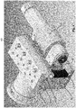
- the first magnetic means 64 (and in particular the electropermanent magnets) are arranged at an external face 612A of the sliding body 612 directed towards the mandrel-holder plate 62.
- two pairs of electropermanent magnets 640 are provided for, while in accordance with the embodiment of figure 9 four pairs of electropermanent magnets 640 are provided for.
- the sliding body 612 is actuatable to slide with respect to the driving body 610 with curved path, i.e. around the common center 100 of the two curvature radii of the two surfaces 611 and 613.
- second movement means 614 are provided for, for moving the sliding body 612 with respect to the driving body 610 around a second substantially vertical rotation axis V and passing through the aforesaid common center 100 of the two curvature radii.
- the machine also comprises second magnetic means 14 suitable to retain the sliding body 612 engaged with the second slide surface 613 thereof within the first slide surface 611 of the driving body 610.
- Second fixing means 140 are also preferably provided for. These are susceptible of locking the sliding body 612 with respect to the driving body 610 in the angular position defined by the second movement means 614.
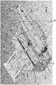
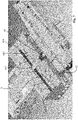
- Such second fixing means 140 are for example constituted by a plurality of screws 141, which thrustingly act against a plate 142, which has a tilted profile 143 which acts against a corresponding tilted profile 144 of the slide plate 612, compressing it against the drive plate 610 as can be seen from the section figure of figure 5 .
- the second magnetic means 14 are permanent magnets aimed to retain the slide surfaces 611, 613 in contact with each other even when the fixing means 140 are loosened in order to allow the adjustment by means of the second movement means 614.
- the second movement means 614 are designed for easily overcoming the magnetic attraction between the sliding body 612 and the driving body 610 and allowing the relative movement thereof.
- the second movement means 614 are for example for such purpose constituted by at least one pair of screws 615, which are axially engaged in threaded seats 616 made in the driving body 610 transversally to the displacement direction of the forming roller 6, or transversally to the movement direction of the linear actuator 7, and act against opposite sides of a block 617 integral with the sliding body 612.
- the block 617 By rotating the two screws 615, for example through a manual tool or a motor, the block 617 is moved within a cavity 618 made in the driving body 610 and thus moves - along the arc subtended between the two slide surfaces - the sliding body 612 with respect to the driving body 610 itself (see figure 7 ).
- the invention thus conceived therefore attains the pre-established objects.
Landscapes
- Engineering & Computer Science (AREA)
- Mechanical Engineering (AREA)
- Transmission Devices (AREA)
- Yarns And Mechanical Finishing Of Yarns Or Ropes (AREA)
Applications Claiming Priority (1)
| Application Number | Priority Date | Filing Date | Title |
|---|---|---|---|
| IT102018000005407A IT201800005407A1 (it) | 2018-05-15 | 2018-05-15 | Macchina rullatrice per formare una filettatura su di un corpo cilindrico |
Publications (1)
| Publication Number | Publication Date |
|---|---|
| EP3575011A1 true EP3575011A1 (fr) | 2019-12-04 |
Family
ID=63080354
Family Applications (1)
| Application Number | Title | Priority Date | Filing Date |
|---|---|---|---|
| EP19174522.3A Withdrawn EP3575011A1 (fr) | 2018-05-15 | 2019-05-14 | Machine de laminage pour former une partie filetée sur un corps cylindrique |
Country Status (2)
| Country | Link |
|---|---|
| EP (1) | EP3575011A1 (fr) |
| IT (1) | IT201800005407A1 (fr) |
Cited By (4)
| Publication number | Priority date | Publication date | Assignee | Title |
|---|---|---|---|---|
| CN112719167A (zh) * | 2020-12-14 | 2021-04-30 | 清远法思特精密五金有限公司 | 一种螺丝的螺杆一次成型装置 |
| CN115365433A (zh) * | 2022-09-09 | 2022-11-22 | 芜湖天科航空科技有限公司 | 一种螺钉加工一体化成形的数字化加工中心 |
| CN115570085A (zh) * | 2022-09-27 | 2023-01-06 | 连云港永誉不锈钢制品有限公司 | 一种高精度钢筋螺纹滚丝设备及其生产方法 |
| IT202200000959A1 (it) * | 2022-01-20 | 2023-07-20 | Evirt Italia S R L | Macchina rullatrice per realizzare impronte su corpi cilindrici e procedimento per sostituire un rullo formatore di detta macchina rullatrice |
Citations (6)
| Publication number | Priority date | Publication date | Assignee | Title |
|---|---|---|---|---|
| EP0894555A2 (fr) * | 1997-07-29 | 1999-02-03 | Revue Thommen AG | Machine à laminer des profilés avec cadre de support |
| JP2002137035A (ja) * | 2000-10-26 | 2002-05-14 | Nissee:Kk | 可変リード転造方法 |
| WO2003000443A1 (fr) * | 2001-06-22 | 2003-01-03 | Nissei Co., Ltd. | Procede de laminage au moyen de filieres rondes |
| JP3678494B2 (ja) * | 1996-04-19 | 2005-08-03 | 株式会社ツガミ | 転造盤の主軸駆動装置 |
| CN104942190A (zh) * | 2015-06-19 | 2015-09-30 | 山东省青岛生建机械厂 | 数控滚轧机 |
| EP3130972A1 (fr) | 2015-08-10 | 2017-02-15 | Mico S.r.l. | Laminoir ameliore destine a former des parties filetees sur des corps cylindriques et procede de formage a asservissement |
-
2018
- 2018-05-15 IT IT102018000005407A patent/IT201800005407A1/it unknown
-
2019
- 2019-05-14 EP EP19174522.3A patent/EP3575011A1/fr not_active Withdrawn
Patent Citations (6)
| Publication number | Priority date | Publication date | Assignee | Title |
|---|---|---|---|---|
| JP3678494B2 (ja) * | 1996-04-19 | 2005-08-03 | 株式会社ツガミ | 転造盤の主軸駆動装置 |
| EP0894555A2 (fr) * | 1997-07-29 | 1999-02-03 | Revue Thommen AG | Machine à laminer des profilés avec cadre de support |
| JP2002137035A (ja) * | 2000-10-26 | 2002-05-14 | Nissee:Kk | 可変リード転造方法 |
| WO2003000443A1 (fr) * | 2001-06-22 | 2003-01-03 | Nissei Co., Ltd. | Procede de laminage au moyen de filieres rondes |
| CN104942190A (zh) * | 2015-06-19 | 2015-09-30 | 山东省青岛生建机械厂 | 数控滚轧机 |
| EP3130972A1 (fr) | 2015-08-10 | 2017-02-15 | Mico S.r.l. | Laminoir ameliore destine a former des parties filetees sur des corps cylindriques et procede de formage a asservissement |
Non-Patent Citations (1)
| Title |
|---|
| DATABASE WPI Derwent World Patents Index; AN 2015-67394B, XP002788666, "Data control rolling mill" * |
Cited By (6)
| Publication number | Priority date | Publication date | Assignee | Title |
|---|---|---|---|---|
| CN112719167A (zh) * | 2020-12-14 | 2021-04-30 | 清远法思特精密五金有限公司 | 一种螺丝的螺杆一次成型装置 |
| CN112719167B (zh) * | 2020-12-14 | 2023-01-10 | 广东法思特精密五金有限公司 | 一种螺丝的螺杆一次成型装置 |
| IT202200000959A1 (it) * | 2022-01-20 | 2023-07-20 | Evirt Italia S R L | Macchina rullatrice per realizzare impronte su corpi cilindrici e procedimento per sostituire un rullo formatore di detta macchina rullatrice |
| CN115365433A (zh) * | 2022-09-09 | 2022-11-22 | 芜湖天科航空科技有限公司 | 一种螺钉加工一体化成形的数字化加工中心 |
| CN115570085A (zh) * | 2022-09-27 | 2023-01-06 | 连云港永誉不锈钢制品有限公司 | 一种高精度钢筋螺纹滚丝设备及其生产方法 |
| CN115570085B (zh) * | 2022-09-27 | 2023-07-21 | 连云港永誉不锈钢制品有限公司 | 一种高精度钢筋螺纹滚丝设备及其生产方法 |
Also Published As
| Publication number | Publication date |
|---|---|
| IT201800005407A1 (it) | 2019-11-15 |
Similar Documents
| Publication | Publication Date | Title |
|---|---|---|
| EP2277662B1 (fr) | Procédé destiné à empierrer des trous de forage tout comme outil à empierrer | |
| US7765844B2 (en) | Prestressed rolling mill housing assembly with improved operational features | |
| US8616037B2 (en) | Re-turning plant for rollers of a roller mill | |
| IT201800005407A1 (it) | Macchina rullatrice per formare una filettatura su di un corpo cilindrico | |
| WO2018099403A1 (fr) | Procédé et appareil d'alimentation en produit semi-fini pour laminage, de réduction de diamètre, d'alignement et de dérouillage, et produit associé | |
| US20120160005A1 (en) | Dimple-forming burnishing tool | |
| AU2012272514C1 (en) | Post-forming method and apparatus | |
| DE102012111999A1 (de) | Maschine zum Vortreiben von Strecken, Tunneln oder dergleichen und Verfahren zur Arbeitskopfansteuerung | |
| CN119927632A (zh) | 一种精密金属零部件加工用钻铣机床 | |
| US3718020A (en) | Rolling mill | |
| EP3429774B1 (fr) | Procédé et appareil permettant la formation d'une spirale pour vis sans fin | |
| US10940527B2 (en) | Manufacturing process, tool stand, and drill bit | |
| JPH01233036A (ja) | 丸棒又は角棒を鍛造するための長物鍛造機 | |
| EP3248706B1 (fr) | Machine de laminage pour former des impressions sur des corps cylindriques et procédé de substitution d'un rouleau d'une machine de laminage | |
| EP3331783B1 (fr) | Poulie de transporteur et procédé de fabrication d'un tube de rouleau | |
| IT201800010872A1 (it) | Macchina rullatrice per formare una filettatura su di un corpo cilindrico | |
| EP3130972A1 (fr) | Laminoir ameliore destine a former des parties filetees sur des corps cylindriques et procede de formage a asservissement | |
| CN120394756A (zh) | 一种异形金属件锻造用稳固夹持装置 | |
| GB2110139A (en) | Roll forging machines | |
| AU1906192A (en) | Selectively formed plate edge method and apparatus | |
| CN214814909U (zh) | 一种用于凸轮轴孔的镗孔加工设备 | |
| DE2208515A1 (fr) | ||
| CN210552678U (zh) | 注塑机动模板的运动导向装置及注塑机 | |
| CN223642718U (zh) | 一种冷镦螺母成型机用后冲螺栓套管装置 | |
| JP2008307578A (ja) | 冷間転造成形機、及びその成形方法 |
Legal Events
| Date | Code | Title | Description |
|---|---|---|---|
| PUAI | Public reference made under article 153(3) epc to a published international application that has entered the european phase |
Free format text: ORIGINAL CODE: 0009012 |
|
| AK | Designated contracting states |
Kind code of ref document: A1 Designated state(s): AL AT BE BG CH CY CZ DE DK EE ES FI FR GB GR HR HU IE IS IT LI LT LU LV MC MK MT NL NO PL PT RO RS SE SI SK SM TR |
|
| AX | Request for extension of the european patent |
Extension state: BA ME |
|
| STAA | Information on the status of an ep patent application or granted ep patent |
Free format text: STATUS: THE APPLICATION IS DEEMED TO BE WITHDRAWN |
|
| 18D | Application deemed to be withdrawn |
Effective date: 20200605 |