EP3575242B1 - Cassette de stockage d'une matière tubulaire - Google Patents
Cassette de stockage d'une matière tubulaire Download PDFInfo
- Publication number
- EP3575242B1 EP3575242B1 EP18174653.8A EP18174653A EP3575242B1 EP 3575242 B1 EP3575242 B1 EP 3575242B1 EP 18174653 A EP18174653 A EP 18174653A EP 3575242 B1 EP3575242 B1 EP 3575242B1
- Authority
- EP
- European Patent Office
- Prior art keywords
- cassette housing
- cassette
- receiving area
- lid foil
- circumferential
- Prior art date
- Legal status (The legal status is an assumption and is not a legal conclusion. Google has not performed a legal analysis and makes no representation as to the accuracy of the status listed.)
- Active
Links
Images

Classifications
-
- B—PERFORMING OPERATIONS; TRANSPORTING
- B65—CONVEYING; PACKING; STORING; HANDLING THIN OR FILAMENTARY MATERIAL
- B65F—GATHERING OR REMOVAL OF DOMESTIC OR LIKE REFUSE
- B65F1/00—Refuse receptacles; Accessories therefor
- B65F1/04—Refuse receptacles; Accessories therefor with removable inserts
- B65F1/06—Refuse receptacles; Accessories therefor with removable inserts with flexible inserts, e.g. bags or sacks
- B65F1/062—Refuse receptacles; Accessories therefor with removable inserts with flexible inserts, e.g. bags or sacks having means for storing or dispensing spare bags
Definitions
- the invention relates to a cassette for storing tubing material, with a cassette housing which has a circumferential receiving area for receiving tubing material and an opening connected to the receiving area for removing tubing material arranged within the receiving area, and a cover film which covers the opening of the cassette housing at least in sections closed, the cover film being welded to the cassette housing along one or more sealing surfaces in each case by means of a welded connection.
- the invention relates to a method for producing a cassette for storing tubing material, with the steps: providing a cassette housing, which has a circumferential receiving area for receiving tubing material and an opening connected to the receiving area for removing tubing material arranged within the receiving area, and filling the receiving area of the cassette housing with tubing.
- Cassettes stocking tubing material usually have a cassette housing in which several meters of tubing material are inserted in a folded and compressed form. So that the folded and compressed tubing material can be held within the cassette housing, known cassettes either have a separate lid or the cassette housing includes an integrated lid section. Corresponding constructions, however, require comparatively high production and assembly costs and/or lead to a considerable impairment of user comfort.
- the object on which the invention is based is therefore to reduce the production costs of cassettes for storing hose material without impairing the ease of use.
- a cassette of the type mentioned at the outset wherein at least one welded connection between the cassette housing and the cover film is designed as a peel connection which can be released by applying a peeling force to the cover film or part of the cover film.
- the invention makes use of the knowledge that the mechanical properties of film material are suitable for holding the folded and compressed tubing within the receiving area of the cassette housing.
- the need for a separate lid or the integration of a lid section into the cassette housing is thus eliminated, so that the manufacturing cost of the cassette is greatly reduced.
- the cover film of the cassette according to the invention can be designed so that it can be torn and/or at least partially pulled off the cassette housing in such a way that the opening of the cassette housing is only partially exposed, which means that a suitable amount of tubing material can be removed in a controlled manner, while tubing material that is not required is inside of the recording area of the cassette case.
- the cassette case is made of a plastic material formed, for example from polypropylene.
- the tubular material can be designed as a tubular film, for example.
- the tube material can be transparent or partially transparent, for example.
- the tube material can also be designed to be essentially opaque.
- the tube material can be colored and/or printed.
- the cassette according to the invention can already comprise the tubing material, the tubing material in this case being arranged in the circumferential receiving area of the cassette housing, in particular in a folded and/or compressed form.
- the cassette housing can be designed in one piece or in several pieces.
- the cover film can be transparent or partially transparent, for example. Alternatively, the cover film can also be designed to be essentially opaque.
- the cover film can be colored and/or printed.
- the cassette according to the invention has a substantially ring-shaped cassette housing.
- the inner contour and/or the outer contour of the cassette housing can, for example, be essentially round or polygonal.
- the cassette housing preferably has a central recess through which the hose material pulled out of the receiving area of the cassette housing extends when the cassette is in use.
- the cover film of the cassette according to the invention can have a ring-shaped basic shape.
- the outer contour and/or the inner contour of the ring-shaped cover film can be essentially round or polygonal.
- the cover film preferably has a central recess through which the tubular material pulled out of the receiving area of the cassette housing extends when the cassette is in use.
- the central recess of the cassette housing and the central recess of the cover film are preferably arranged coaxially with one another.
- the cover film is joined along one or more, preferably circumferential, sealing surfaces by means of a welded connection welded to the cassette case.
- the cover film is attached to the cassette housing by the one or more welded joints.
- the one or more welded connections are designed in such a way that the one or more welded connections cannot be released by a pressure load on the compressed hose material within the receiving area of the cassette housing.
- the cover film is welded along an outer circumferential sealing surface by means of a welded connection to a material section of the cassette housing which is arranged radially on the outside of the receiving area.
- the cover film is welded along an inner peripheral sealing surface by means of a welded connection to a material section of the cassette housing, which is arranged radially on the inside of the receiving area.
- the peripheral sealing surfaces of the cover film and the welded material sections of the cassette housing are preferably ring-shaped and have a width in the range from 3 to 8 mm, preferably a width in the range from 4 to 5 mm.
- the outer sealing surface is wider than the inner sealing surface.
- the material section of the cassette housing which is arranged radially on the outside of the receiving area, is designed as an outwardly extending and preferably circumferential housing web.
- the material section of the cassette housing which is arranged radially on the inside of the receiving area, is designed as an inwardly extending and preferably circumferential housing web.
- the outwardly extending housing web is preferably connected to a substantially cylindrical outer lateral surface of the cassette housing via a bent material section.
- the outer lateral surface of the cassette housing can have a slight inclination so that a draft angle is implemented.
- the inwardly extending housing web is preferably a curved portion of material with a substantially cylindrical inner lateral surface of the cassette housing, which defines the central recess of the cassette housing.
- the inner lateral surface of the cassette housing can have a slight inclination, so that a draft angle is implemented. Due to the housing web extending outwards and the housing web extending inwards, planar welded connections can be implemented with the cover film without reducing the size of the opening of the cassette housing connected to the receiving area.
- the welded joints between the cassette housing and the cover film have different adhesive properties.
- the different adhesive properties of the welded joints mean that the welded joints have different resistance properties when the lid film is subjected to mechanical stress. If a peeling force is applied to the cover foil in order to detach the cover foil or a part of the cover foil from the cassette housing, the different adhesive properties of the welded joints mean that the welded joint which has the lowest resistance force is released first. If the cover film is equipped with predetermined tear lines, it can be achieved in this way that only part of the cover film is detached from the cassette housing when the cover film is subjected to a peeling force.
- At least one welded connection between the cassette housing and the cover film is designed as a peel connection, which can be released by applying a peeling force to the cover film or part of the cover film.
- the peel connection allows at least part of the cover film to be pulled off the cassette housing quickly and easily, so that the opening of the cassette housing is released at least in sections for removing the tubing material arranged within the receiving area.
- a cassette according to the invention is advantageous in which the cover film has one or more predetermined tear lines, in particular perforation lines, has, which preferably extend at least partially in the circumferential direction.
- the one or more lines of weakness can comprise a plurality of recesses which extend partially or completely through the lidding film.
- the recesses are material indentations in the area of which the material thickness of the cover film is reduced. If the recesses extend completely through the cover foil, the recesses are through holes.
- a predetermined tear line with a plurality of through holes extending through the lid film is implemented via the one or more perforation lines, along which the lid film tears when the lid film is subjected to a peeling force.
- the adhesive properties of the welded joints between the cassette housing and the lid film and the one or more predetermined tear lines are coordinated in such a way that when the lid film is subjected to a peeling force, a welded joint between the cassette housing and the lid film is released and the lid film tears along one or more predetermined tear lines and a welded joint remains between the cassette body and the cover sheet.
- a peeling force to the lid film, only a part of the lid film can be detached from the cassette housing, with another part remaining attached to the cassette housing.
- pulling off the detachable part of the cover film creates a circumferential slot through which the tube material arranged in the receiving area of the cassette housing can be removed via the opening of the cassette housing.
- the one or more predetermined tear lines divide the cover film into a preferably circumferential peel-off area and a preferably circumferential closure area.
- the pull-off portion is preferably welded to a portion of material of the cartridge case that is located radially inward of the receiving portion.
- the closure area is preferably welded to a material portion of the cassette housing, which is radially outward of the Recording area is arranged.
- the pull-off area and the closure area of the lid film have ring-shaped basic shapes and/or different material widths.
- the pull-off area on the inside is narrower than the sealing area on the outside of the cover film.
- a cassette according to the invention is advantageous in which the cover film has one or more grip tabs which are designed to be gripped by a user in order to apply a peeling force to the cover film.
- the grip tabs can be formed, for example, by cuts within the cover film.
- the cover film can be designed in such a way that the opposing cut edges adhere to one another or border one another.
- the grip tabs are preferably designed in such a way that they first have to be pushed open by the user, in particular by a finger of the user, before they can be grasped by the user.
- the one or more gripping tabs represent components of the pull-off area of the lidding film.
- the object on which the invention is based is also achieved by a method according to claim 9 .
- the provision of the cassette housing can, for example, include the production of the cassette housing in an injection molding process.
- the filling of the receiving area of the cassette housing with tubing is preferably carried out via a vertical filling, wherein during the vertical Filling a fold of the tubing is caused within the receiving area of the cassette housing.
- the at least partially closing of the opening of the cassette housing with a cover film comprises positioning the cover film on the opening of the cassette housing, creating a first, preferably circumferential, welded joint between the cassette housing and the cover film and/or creating a second, preferably circumferential, welded connection between the cassette housing and the cover film.
- the production of the first welded joint and/or the production of the second welded joint preferably takes place by introducing thermal energy into the intended welding area.
- a sealing temperature is generated in the welded area of the first welded joint and/or in the welded area of the second welded joint, which causes the cover film to be sealed on the cassette housing.
- the first, preferably circumferential, welded connection between the cassette housing and the cover film is produced at a first welding temperature and the second, preferably circumferential, welded connection between the cassette housing and the cover film is produced at a second welding temperature.
- first welding temperature and the second welding temperature are different from each other.
- the first welding temperature and the second welding temperature preferably differ by at least 5°C, by at least 10°C, by at least 15°C, by at least 20°C, by at least 25°C or by at least 30°C.
- an outer and an inner circumferential welded connection is produced, the welding temperature when producing the outer welded connection being higher than the welding temperature when producing the inner welded connection.
- the inner Welded connection can be released with less effort. This allows the implementation of a cover film which is only partially detached from the cassette housing when subjected to a pull-off force.
- a method according to the invention is advantageous in which the production of the first, preferably circumferential, welded connection between the cassette housing and the cover film and the production of the second, preferably circumferential, welded connection between the cassette housing and the cover film take place essentially at the same time or at different times.
- the simultaneous production of the first and the second welded connection can be achieved in particular with a welding or sealing tool which has a plurality of, at least two, temperature zones.
- the production of the first, preferably circumferential, welded connection between the cassette housing and the cover foil and/or the production of the second, preferably circumferential, welded connection between the cassette housing and the cover foil can be effected by single or multiple application of heat. If heat is applied several times, the welding temperatures set for the heat inputs can be identical or deviate from one another.
- the method according to the invention can also include loading the tubing filled into the receiving area of the cassette housing with a loading object, namely in such a way that the tubing filled into the receiving area of the cassette housing is at least temporarily compressed.
- the method according to the invention comprises moving the cassette housing filled with the tubing material, in particular together with the load object, into a closed position in which the opening of the cassette housing is closed at least in sections with the cover film.
- the load object can, for example, be designed to be circumferential and/or have a ring shape.
- the hose material arranged in the receiving area of the cassette housing is pressed down in such a way that at least temporarily no Tubing material protrudes from the opening of the cassette housing, so that the cover film can be put on and the cover film can be welded without there being any tubing material in the welding area between the cover film and the cassette housing.
- the compression is released, so that only a limited time window is available for positioning and welding the cover film to the cassette housing.
- the sealing of the cover film preferably takes place in a separate sealing system.
- a method according to the invention is preferred in which a predetermined tear line that can be torn, in particular a perforation that can be torn, is produced in the lid film.
- the method includes the provision of a cover film which already has one or more predetermined tear lines, in particular perforation lines.
- the opening of the cassette housing is preferably closed at least in sections with a cover film which already has one or more tearable predetermined tear lines, in particular perforation lines.
- one or more grip tabs are produced in the lidding film as part of the method according to the invention. The gripping tabs are used for gripping by a user so that a user can apply a peeling force to the lidding film.
- a predetermined tear line in particular a perforation, is torn in the cover film.
- the tearable predetermined tear line is preferably produced in the cover film by laser perforation.
- the cassette 10 has a cassette housing 12 and a cover film 18 .
- the cassette housing 12 is designed as a one-piece plastic body and has an essentially ring-shaped basic shape.
- the cassette housing 12 can be made of polypropylene and can be injection molded.
- the cassette housing 12 comprises a peripheral receiving area 14 for receiving tubing 100 and an opening 16 connected to the receiving area 14 for removing the tubing 100 arranged within the receiving area 14.
- the cover film 18 closes the opening 16 of the cassette housing 12 and prevents unfolding of the folded and compressed hose material 100.
- the tubular material 100 is designed as a transparent tubular film which was introduced by vertical filling of the receiving area 14 of the cassette housing 12 , with the tubular material 100 being folded while the receiving area 14 of the cassette housing 12 is being filled.
- the cassette housing 12 has an essentially cylindrical outer wall 20 and an essentially cylindrical inner wall 22 , the outer wall 20 and the inner wall 22 being connected to one another by means of a cassette base 24 .
- the outer wall 20 and the inner wall 22 each have a slight inclination, so that a draft angle is implemented in each case.
- the ring segment of the cassette body thus has an essentially U-shaped cross section.
- the cover film 14 also has an annular basic shape. Due to their ring shape, the cassette housing 12 and the cover film 18 each have a central recess 26, 28, with the recesses 26, 28 being arranged essentially in a circle and coaxially with one another.
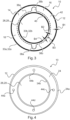
- the 3 shows that the cover film 18 is welded to the cassette housing 12 along two circumferential and essentially ring-shaped sealing surfaces 30a, 30b.
- the cover foil 18 is welded along an outer circumferential sealing surface 30a to an annular material section 32a of the cassette housing 12 which is arranged radially outwards from the receiving area 14 .
- the cover film 18 is welded along an inner circumferential sealing surface 30b to an annular material section 32b of the cassette housing 12 which is arranged radially inward from the receiving area 14 .
- the tubular material 100 filled into the receiving area 14 of the cassette housing 12 is loaded with a load object in such a way that the tubular material 100 filled into the receiving area 14 of the cassette housing 12 is temporarily strongly compressed.
- the strong compression of the tubular material 100 allows the opening 16 of the cassette housing 12 to be closed with the cover film 18 and the cover film 18 to be welded without there being any tubing material 100 between the sealing surfaces 30a, 30b of the cover film 18 and the material sections 32a, 32b of the cassette housing 12 .
- the outer peripheral sealing surface 30a of the cover film 18 and the outer peripheral material section 32a of the cassette housing 12 have a width B1 of 5 mm.
- the inner peripheral sealing surface 30b of the lid film 18 and the inner peripheral material portion 32b of the cassette case 12 have a width B2 of 4mm.
- the outer peripheral sealing surface 30a of the lid film 18 and the outer peripheral material portion 32a of the cartridge body 12 is coaxial with the inner peripheral sealing surface 30b of the cover film 18 and the inner peripheral material portion 32b of the cassette housing 12 is arranged.
- outer circumferential sealing surface 30a of the lid foil 18 and the outer circumferential material section 32a of the cassette housing 12 have a larger diameter than the inner circumferential sealing surface 30b of the lid foil 18 and the inner circumferential material section 32b of the cassette housing 12.
- the welded joints between the cassette housing 12 and the cover film 18 have different adhesive properties.
- the different adhesive properties are achieved in that the weld between the outer circumferential sealing surface 30a of the lid film 18 and the outer circumferential material section 32a of the cassette housing 12 is produced at a higher temperature than the weld between the inner circumferential sealing surface 30b of the lid film 18 and the inner circumferential Material section 32b of the cassette housing 12.
- the production of the two peripheral welded joints between the cassette housing 12 and the cover film 18 takes place essentially at the same time.
- the welded connection between the inner circumferential sealing surface 30b of the cover film 18 and the inner circumferential material section 32b of the cassette housing 12 is designed as a peel connection, which can be detached by applying a peeling force to the cover film 18 .
- the welded connection between the outer circumferential sealing surface 30a of the lid foil 18 and the outer circumferential material section 32a of the cassette housing 12 has a higher strength than the welded connection between the inner circumferential sealing surface 30b of the lid foil 18 and the inner circumferential material section 32b of the cassette housing 12 and is not without Also detachable by applying a peeling force to the cover film 18 .
- the cover film 18 has two perforation lines 36a, 36b arranged on a circular path, which are connected to one another via two grip tabs 38a, 38b.
- the perforation lines 36a, 36b divide the cover film 18 into a circumferential peel-off area 40 and a circumferential closure area 42.
- the peel-off area 40 is welded to the material section 30b of the cassette housing 12, which is arranged radially inward from the receiving area 14.
- the closure area 42 is welded to the material section 30a of the cassette housing 12 which is arranged radially outwards from the receiving area 14 .
- the closure area 42 has the width B3.
- the peeling area 40 has the width B4.
- the closure area 42 is wider than the pull-off area 40 so that after the pull-off area 40 has been pulled off, there is a circumferential slit through which the hose material 100 can be removed from the receiving area 14 .
- the wide closure area 42 also serves to hold down the folded tubing 100 arranged within the receiving area 14 after the pull-off area 40 has been pulled off.
- the grip tabs 38a, 38b can be gripped by a user in order to apply a peeling force to the cover film 18.
- the grip tabs 38a, 38b are cut out of the cover film 18, with the cut edges lying opposite one another abutting and adhering to one another.
- the 4 shows the cassette base 24 of a cassette 10.
- the cassette base 24 there are several recesses 44a-44d, which are designed as through holes.
- the recesses 44a-44d connect the receiving area 14 of the cassette housing 12 with the surroundings of the cassette base 24.
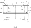
- the figure 5 shows that the recesses 44a-44d serve to receive material projections 204a, 204c of a cassette receiving device 200 of a container construction.
- the material projections 204a, 20c can be designed as pins, for example.
- the material projections 204a, 204c are dimensioned and arranged such that after the cassette 10 has been inserted into an insertion area 202 of the cassette receiving device 200, the material projections 204a, 204c protrude into the receiving area 14 of the cassette housing 12 and are in contact with the tubing 100 located in the receiving area 14.
- the edges of the material projections 204a, 204c are rounded so that the hose material 100 is not damaged by the material projections 204a, 204c.
- the material section 32a of the cassette housing 12, which is arranged radially on the outside of the receiving area 14, is designed as an outwardly extending and circumferential housing web 34a.
- the material section 32b of the cassette housing 12, which is arranged radially on the inside of the receiving area 14, is designed as an inwardly extending and circumferential housing web 34b.
Landscapes
- Engineering & Computer Science (AREA)
- Mechanical Engineering (AREA)
- Packaging Of Annular Or Rod-Shaped Articles, Wearing Apparel, Cassettes, Or The Like (AREA)
- Packages (AREA)
Claims (14)
- Cassette (10) de stockage de matériau tubulaire (100), dotée- d'un boîtier de cassette (12) qui présente une zone de réception (14) périphérique pour recevoir du matériau tubulaire (100) et une ouverture (16) reliée à la zone de réception (14) pour retirer du matériau tubulaire (100) agencé à l'intérieur de la zone de réception ; et- d'une feuille de couverture (18) qui ferme au moins partiellement l'ouverture (16) du boîtier de cassette (12), ladite feuille de couverture (18) étant soudée au boîtier de cassette (12) le long d'une ou de plusieurs surfaces de scellement (30a, 30b) respectivement au moyen d'une liaison soudée ;caractérisée en ce qu'au moins une liaison soudée est formée entre le boîtier de cassette (12) et la feuille de couverture (18) sous forme de liaison pelable qui peut être détachée en soumettant la feuille de couverture (18) ou une partie de ladite feuille de couverture (18) à une force de décollement.
- Cassette (10) selon la revendication 1,
caractérisée en ce que la ou les plusieurs surfaces de scellement (30a, 30b) sont des surfaces de scellement périphériques (30a, 30b). - Cassette (10) selon la revendication 1 ou 2,
caractérisée en ce que la feuille de couverture (18) est, le long d'une surface de scellement (30a) périphérique extérieure, soudée à l'aide d'une liaison soudée à une section de matériau (32a) du boîtier de la cassette (12) qui est agencée radialement à l'extérieur de la zone de réception (14), et/ou, le long d'une surface de scellement (30b) périphérique intérieure, soudée à l'aide d'une liaison soudée à une section de matériau (32b) du boîtier de la cassette (12) qui est agencée radialement à l'intérieur de la zone de réception (14). - Cassette (10) selon la revendication 3,
caractérisée en ce que la section de matériau (32a) du boîtier de la cassette (12) qui est agencée radialement à l'extérieur de la zone de réception (14), est formée sous forme d'un méplat de boîtier (34a) s'étendant vers l'extérieur et de préférence périphérique, et/ou que la section de matériau (32b) du boîtier de la cassette (12) qui est agencée radialement à l'intérieur de la zone de réception (14) est formée sous forme d'un méplat de boîtier (34b) s'étendant vers l'intérieur et de préférence périphérique. - Cassette (10) selon l'une quelconque des revendications 2 à 4,
caractérisée en ce que les liaisons soudées entre le boîtier de la cassette (12) et la feuille de couverture (18) présentent des propriétés d'adhérence différentes. - Cassette (10) selon l'une quelconque des revendications précédentes,
caractérisée en ce que la feuille de couverture (18) présente une ou plusieurs lignes de déchirure voulue (36a, 36b), notamment des lignes de perforation, qui s'étendent de préférence au moins partiellement dans le sens périphérique. - Cassette (10) selon la revendication 6,
caractérisée en ce que ladite une ou lesdites plusieurs lignes de déchirure voulue (36a, 36b) divisent la feuille de couverture (18) en une zone de décollement (40) de préférence périphérique, et en une zone de fermeture (42), de préférence périphérique, ladite zone de décollement (40) étant soudée à une section de matériau (30b) du boîtier de la cassette (12) qui est agencée radialement à l'intérieur de la zone de réception (14), et ladite zone de fermeture (42) étant soudée à une section de matériau (30b) du boîtier de la cassette (12) qui est agencée radialement à l'extérieur de la zone de réception (14). - Cassette (10) selon l'une quelconque des revendications précédentes, caractérisée en ce que la feuille de couverture (18) présente une ou plusieurs languettes de préhension (38a, 38b) qui sont destinées à être saisies par un utilisateur pour appliquer une force de décollement à la feuille de couverture (18).
- Procédé de fabrication d'une cassette (10) selon l'une quelconque des revendications précédentes, comprenant les étapes suivantes :- fourniture d'un boîtier de cassette (12) qui présente une zone de réception (14) périphérique pour recevoir du matériau tubulaire (100) et une ouverture (16) reliée à la zone de réception (14) pour retirer du matériau tubulaire (100) agencé à l'intérieur de la zone de réception (14) ;- remplissage de ladite zone de réception (14) du boîtier de la cassette (12) avec du matériau tubulaire (100) ; et- fermeture de l'ouverture (16) du boîtier de la cassette (12), au moins partiellement à l'aide d'une feuille de couverture (18).
- Procédé selon la revendication 9,
caractérisé en ce que la fermeture de l'ouverture (16) du boîtier de la cassette (12), au moins partiellement à l'aide d'une feuille de couverture (18), comprend au moins l'une des étapes suivantes :- positionnement de la feuille de couverture (18) sur l'ouverture (16) du boîtier de la cassette (12) ;- création d'une première liaison soudée, de préférence périphérique, entre le boîtier de la cassette (12) et la feuille de couverture (18) ;- création d'une deuxième liaison soudée, de préférence périphérique, entre le boîtier de la cassette (12) et la feuille de couverture (18). - Procédé selon la revendication 10,
caractérisé en ce que la création d'une première liaison soudée, de préférence périphérique, entre le boîtier de la cassette (12) et la feuille de couverture (18) s'effectue à une première température de soudage et la création d'une deuxième liaison soudée, de préférence périphérique, entre le boîtier de la cassette (12) et la feuille de couverture (18) s'effectue à une deuxième température de soudage, la première température de soudage étant différente de la deuxième température de soudage. - Procédé selon la revendication 10 ou 11,
caractérisé en ce que la création de la première liaison soudée, de préférence périphérique, entre le boîtier de la cassette (12) et la feuille de couverture (18), et la création de la deuxième liaison soudée, de préférence périphérique, entre le boîtier de la cassette (12) et la feuille de couverture (18) s'effectuent sensiblement simultanément ou en différé. - Procédé selon l'une quelconque des revendications 9 à 12,
caractérisé par au moins une des étapes suivantes :- chargement du matériau tubulaire (100) déposé dans la zone de réception (14) du boîtier de la cassette (12), avec un objet de charge de telle sorte que le matériau tubulaire (100) déposé dans la zone de réception (14) du boîtier de la cassette (12) soit comprimé au moins temporairement ;- mise du boîtier de la cassette (12) rempli du matériau tubulaire (100), notamment avec l'objet de charge, dans une position de fermeture dans laquelle s'effectue la fermeture de l'ouverture (16) du boîtier de la cassette (12) au moins partiellement avec la feuille de couverture (18). - Procédé selon l'une quelconque des revendications 9 à 13,
caractérisé par au moins une des étapes suivantes :- création d'une ligne de déchirure voulue déchirable, notamment d'une perforation déchirable, dans la feuille de couverture (18) ;- création, notamment découpe, d'une ou de plusieurs languettes de préhension (38a, 38b) dans la feuille de couverture (18).
Priority Applications (3)
| Application Number | Priority Date | Filing Date | Title |
|---|---|---|---|
| EP18174653.8A EP3575242B1 (fr) | 2018-05-28 | 2018-05-28 | Cassette de stockage d'une matière tubulaire |
| EP23176090.1A EP4223665B1 (fr) | 2018-05-28 | 2018-05-28 | Cassette pour l'approvisionnement de matériau tubulaire |
| PCT/EP2019/058597 WO2019228694A1 (fr) | 2018-05-28 | 2019-04-05 | Cassette de stockage de matériau tubulaire souple |
Applications Claiming Priority (1)
| Application Number | Priority Date | Filing Date | Title |
|---|---|---|---|
| EP18174653.8A EP3575242B1 (fr) | 2018-05-28 | 2018-05-28 | Cassette de stockage d'une matière tubulaire |
Related Child Applications (2)
| Application Number | Title | Priority Date | Filing Date |
|---|---|---|---|
| EP23176090.1A Division-Into EP4223665B1 (fr) | 2018-05-28 | 2018-05-28 | Cassette pour l'approvisionnement de matériau tubulaire |
| EP23176090.1A Division EP4223665B1 (fr) | 2018-05-28 | 2018-05-28 | Cassette pour l'approvisionnement de matériau tubulaire |
Publications (2)
| Publication Number | Publication Date |
|---|---|
| EP3575242A1 EP3575242A1 (fr) | 2019-12-04 |
| EP3575242B1 true EP3575242B1 (fr) | 2023-08-16 |
Family
ID=62455406
Family Applications (2)
| Application Number | Title | Priority Date | Filing Date |
|---|---|---|---|
| EP18174653.8A Active EP3575242B1 (fr) | 2018-05-28 | 2018-05-28 | Cassette de stockage d'une matière tubulaire |
| EP23176090.1A Active EP4223665B1 (fr) | 2018-05-28 | 2018-05-28 | Cassette pour l'approvisionnement de matériau tubulaire |
Family Applications After (1)
| Application Number | Title | Priority Date | Filing Date |
|---|---|---|---|
| EP23176090.1A Active EP4223665B1 (fr) | 2018-05-28 | 2018-05-28 | Cassette pour l'approvisionnement de matériau tubulaire |
Country Status (2)
| Country | Link |
|---|---|
| EP (2) | EP3575242B1 (fr) |
| WO (1) | WO2019228694A1 (fr) |
Families Citing this family (4)
| Publication number | Priority date | Publication date | Assignee | Title |
|---|---|---|---|---|
| US20170233183A1 (en) * | 2016-01-28 | 2017-08-17 | Edgewell Personal Care Brands, Llc | Cassette with Non-Uniform Liner Cavity |
| CN111169779B (zh) * | 2020-03-02 | 2023-11-03 | 王艳琴 | 一种方便垃圾分类的可调温容器 |
| WO2022204813A1 (fr) * | 2021-03-30 | 2022-10-06 | Angelcare Canada Inc. | Cassette de distribution de film de systèmes d'élimination de déchets |
| CN113443297B (zh) * | 2021-08-10 | 2023-02-10 | 杭州祺来电子有限公司 | 一种垃圾桶用长筒塑料膜袋及其包装方法、包装模具 |
Family Cites Families (6)
| Publication number | Priority date | Publication date | Assignee | Title |
|---|---|---|---|---|
| US3536192A (en) * | 1969-02-17 | 1970-10-27 | John R Couper | Container for incremental withdraw of tubular plastic |
| GB0114312D0 (en) * | 2001-06-12 | 2001-08-01 | Sangenic International Ltd | Spool for a waste storage device |
| GB2232951B (en) * | 1989-06-19 | 1993-02-24 | Process Improvements Ltd | Apparatus for producing layered tubes or rings |
| US5671847A (en) * | 1994-10-27 | 1997-09-30 | Pedersen; Constance Rebecca | Trash bag dispenser |
| US20050079372A1 (en) * | 2003-10-09 | 2005-04-14 | Schmal Michael D. | Polyester films and methods for making the same |
| JP2011057383A (ja) * | 2009-09-10 | 2011-03-24 | Aprica Children's Products Kk | 汚物処理装置用詰替フィルム、詰替フィルム収納用カセット、および携帯用汚物処理袋 |
-
2018
- 2018-05-28 EP EP18174653.8A patent/EP3575242B1/fr active Active
- 2018-05-28 EP EP23176090.1A patent/EP4223665B1/fr active Active
-
2019
- 2019-04-05 WO PCT/EP2019/058597 patent/WO2019228694A1/fr not_active Ceased
Also Published As
| Publication number | Publication date |
|---|---|
| WO2019228694A1 (fr) | 2019-12-05 |
| EP4223665A1 (fr) | 2023-08-09 |
| EP3575242A1 (fr) | 2019-12-04 |
| EP4223665B1 (fr) | 2025-03-26 |
Similar Documents
| Publication | Publication Date | Title |
|---|---|---|
| DE3148537C2 (de) | Verfahren zur Herstellung eines endseitig verschlossenen zusammengesetzten Behälters durch Reibschweißen | |
| DE102004047445B4 (de) | Nichtwiederverschließbare Verpackung für gesundheitsgefährdende Erzeugnisse, Verwendung der Verpackung, sowie Verfahren zu deren Herstellung | |
| EP0700835B1 (fr) | Sac en feuille de matière plastique | |
| DE2524489A1 (de) | Beutel, insbesondere urinbeutel, sowie verfahren zur herstellung eines beutels aus waermeverschweissbarer kunststoff-folie | |
| EP4223665B1 (fr) | Cassette pour l'approvisionnement de matériau tubulaire | |
| EP1392569B1 (fr) | Systeme de bouchage pour flacon de medicaments et procede permettant de le produire | |
| WO1999065791A1 (fr) | Piece a souder en matiere plastique indeformable | |
| EP0424649A1 (fr) | Emballage de produits à écoulement libre | |
| DE3006292A1 (de) | Aufbrechbares behaelter-verschlusselement, mit einem solchen verschlusselement versehener blutbeutel und verfahren zum verschliessen eines flexiblen behaelters mit einem solchen verschlusselement | |
| EP4228976B1 (fr) | Couvercle de boîte et procédé de fabrication d'un couvercle de boîte | |
| WO1995003976A1 (fr) | Emballage pour substances liquides pourvu d'un dispositif de deversement, procede de fabrication d'un emballage pour substances liquides et outil de mise en ×uvre dudit procede | |
| WO2010010130A2 (fr) | Emballage refermable comportant une membrane pelable | |
| EP0676336A2 (fr) | Procédé de recouvrement du bord coupant d'une ouverture de récipient au moyen d'un recouvrement de protection | |
| EP1218255B1 (fr) | Procédé d'étanchéification de l'embouchure d'un récipient | |
| DE102011086278A1 (de) | Entleerverfahren und Entleervorrichtung für ein kontaminationsfreies Entleeren eines zumindest teilweise flexiblen Gebindes | |
| EP1205393B1 (fr) | Couvercle de boíte et sa méthode de fabrication | |
| CH668754A5 (de) | Verfahren zum verschliessen eines dosenartigen behaelters mittels einer membran. | |
| DE2234623A1 (de) | Behaelterverschluss mit schutzfuge und verfahren zur herstellung desselben | |
| DE2647775A1 (de) | Vorrichtung zum loesbaren verschliessen der offenen stirnseite eines rohrfoermigen behaelters | |
| EP0663884A1 (fr) | Contenant scellable pouvant etre referme apres la premiere ouverture, procede et feuille permettant de le realiser | |
| DE1943349C3 (de) | Sicherungsring für Flaschen oder ähnliche Behälter sowie Verfahren zu deren Sicherung | |
| DE69213211T2 (de) | Behälterverschluss mit Abreissband | |
| DE2735836A1 (de) | Verschlussdeckel fuer behaelter | |
| DE10359036B4 (de) | Verfahren zum Verschweißen eines becherartigen Behälters und Werkzeug zur Durchführung des Verfahrens | |
| EP0735976A1 (fr) | Dispositif pour l'ouverture d'un emballage |
Legal Events
| Date | Code | Title | Description |
|---|---|---|---|
| PUAI | Public reference made under article 153(3) epc to a published international application that has entered the european phase |
Free format text: ORIGINAL CODE: 0009012 |
|
| STAA | Information on the status of an ep patent application or granted ep patent |
Free format text: STATUS: THE APPLICATION HAS BEEN PUBLISHED |
|
| AK | Designated contracting states |
Kind code of ref document: A1 Designated state(s): AL AT BE BG CH CY CZ DE DK EE ES FI FR GB GR HR HU IE IS IT LI LT LU LV MC MK MT NL NO PL PT RO RS SE SI SK SM TR |
|
| AX | Request for extension of the european patent |
Extension state: BA ME |
|
| RAP1 | Party data changed (applicant data changed or rights of an application transferred) |
Owner name: BAVENDIEK, KEVIN |
|
| RIN1 | Information on inventor provided before grant (corrected) |
Inventor name: BAVENDIEK, KEVIN Inventor name: LEHMANN, ROBERT |
|
| STAA | Information on the status of an ep patent application or granted ep patent |
Free format text: STATUS: REQUEST FOR EXAMINATION WAS MADE |
|
| 17P | Request for examination filed |
Effective date: 20200414 |
|
| RBV | Designated contracting states (corrected) |
Designated state(s): AL AT BE BG CH CY CZ DE DK EE ES FI FR GB GR HR HU IE IS IT LI LT LU LV MC MK MT NL NO PL PT RO RS SE SI SK SM TR |
|
| STAA | Information on the status of an ep patent application or granted ep patent |
Free format text: STATUS: EXAMINATION IS IN PROGRESS |
|
| 17Q | First examination report despatched |
Effective date: 20220523 |
|
| GRAP | Despatch of communication of intention to grant a patent |
Free format text: ORIGINAL CODE: EPIDOSNIGR1 |
|
| STAA | Information on the status of an ep patent application or granted ep patent |
Free format text: STATUS: GRANT OF PATENT IS INTENDED |
|
| INTG | Intention to grant announced |
Effective date: 20230403 |
|
| GRAS | Grant fee paid |
Free format text: ORIGINAL CODE: EPIDOSNIGR3 |
|
| GRAA | (expected) grant |
Free format text: ORIGINAL CODE: 0009210 |
|
| STAA | Information on the status of an ep patent application or granted ep patent |
Free format text: STATUS: THE PATENT HAS BEEN GRANTED |
|
| AK | Designated contracting states |
Kind code of ref document: B1 Designated state(s): AL AT BE BG CH CY CZ DE DK EE ES FI FR GB GR HR HU IE IS IT LI LT LU LV MC MK MT NL NO PL PT RO RS SE SI SK SM TR |
|
| REG | Reference to a national code |
Ref country code: CH Ref legal event code: EP |
|
| REG | Reference to a national code |
Ref country code: DE Ref legal event code: R096 Ref document number: 502018012969 Country of ref document: DE |
|
| REG | Reference to a national code |
Ref country code: IE Ref legal event code: FG4D Free format text: LANGUAGE OF EP DOCUMENT: GERMAN |
|
| REG | Reference to a national code |
Ref country code: LT Ref legal event code: MG9D |
|
| REG | Reference to a national code |
Ref country code: NL Ref legal event code: MP Effective date: 20230816 |
|
| PG25 | Lapsed in a contracting state [announced via postgrant information from national office to epo] |
Ref country code: GR Free format text: LAPSE BECAUSE OF FAILURE TO SUBMIT A TRANSLATION OF THE DESCRIPTION OR TO PAY THE FEE WITHIN THE PRESCRIBED TIME-LIMIT Effective date: 20231117 |
|
| PG25 | Lapsed in a contracting state [announced via postgrant information from national office to epo] |
Ref country code: IS Free format text: LAPSE BECAUSE OF FAILURE TO SUBMIT A TRANSLATION OF THE DESCRIPTION OR TO PAY THE FEE WITHIN THE PRESCRIBED TIME-LIMIT Effective date: 20231216 |
|
| PG25 | Lapsed in a contracting state [announced via postgrant information from national office to epo] |
Ref country code: SE Free format text: LAPSE BECAUSE OF FAILURE TO SUBMIT A TRANSLATION OF THE DESCRIPTION OR TO PAY THE FEE WITHIN THE PRESCRIBED TIME-LIMIT Effective date: 20230816 Ref country code: RS Free format text: LAPSE BECAUSE OF FAILURE TO SUBMIT A TRANSLATION OF THE DESCRIPTION OR TO PAY THE FEE WITHIN THE PRESCRIBED TIME-LIMIT Effective date: 20230816 Ref country code: PT Free format text: LAPSE BECAUSE OF FAILURE TO SUBMIT A TRANSLATION OF THE DESCRIPTION OR TO PAY THE FEE WITHIN THE PRESCRIBED TIME-LIMIT Effective date: 20231218 Ref country code: NO Free format text: LAPSE BECAUSE OF FAILURE TO SUBMIT A TRANSLATION OF THE DESCRIPTION OR TO PAY THE FEE WITHIN THE PRESCRIBED TIME-LIMIT Effective date: 20231116 Ref country code: NL Free format text: LAPSE BECAUSE OF FAILURE TO SUBMIT A TRANSLATION OF THE DESCRIPTION OR TO PAY THE FEE WITHIN THE PRESCRIBED TIME-LIMIT Effective date: 20230816 Ref country code: LV Free format text: LAPSE BECAUSE OF FAILURE TO SUBMIT A TRANSLATION OF THE DESCRIPTION OR TO PAY THE FEE WITHIN THE PRESCRIBED TIME-LIMIT Effective date: 20230816 Ref country code: LT Free format text: LAPSE BECAUSE OF FAILURE TO SUBMIT A TRANSLATION OF THE DESCRIPTION OR TO PAY THE FEE WITHIN THE PRESCRIBED TIME-LIMIT Effective date: 20230816 Ref country code: IS Free format text: LAPSE BECAUSE OF FAILURE TO SUBMIT A TRANSLATION OF THE DESCRIPTION OR TO PAY THE FEE WITHIN THE PRESCRIBED TIME-LIMIT Effective date: 20231216 Ref country code: HR Free format text: LAPSE BECAUSE OF FAILURE TO SUBMIT A TRANSLATION OF THE DESCRIPTION OR TO PAY THE FEE WITHIN THE PRESCRIBED TIME-LIMIT Effective date: 20230816 Ref country code: GR Free format text: LAPSE BECAUSE OF FAILURE TO SUBMIT A TRANSLATION OF THE DESCRIPTION OR TO PAY THE FEE WITHIN THE PRESCRIBED TIME-LIMIT Effective date: 20231117 Ref country code: FI Free format text: LAPSE BECAUSE OF FAILURE TO SUBMIT A TRANSLATION OF THE DESCRIPTION OR TO PAY THE FEE WITHIN THE PRESCRIBED TIME-LIMIT Effective date: 20230816 |
|
| PG25 | Lapsed in a contracting state [announced via postgrant information from national office to epo] |
Ref country code: PL Free format text: LAPSE BECAUSE OF FAILURE TO SUBMIT A TRANSLATION OF THE DESCRIPTION OR TO PAY THE FEE WITHIN THE PRESCRIBED TIME-LIMIT Effective date: 20230816 |
|
| PG25 | Lapsed in a contracting state [announced via postgrant information from national office to epo] |
Ref country code: ES Free format text: LAPSE BECAUSE OF FAILURE TO SUBMIT A TRANSLATION OF THE DESCRIPTION OR TO PAY THE FEE WITHIN THE PRESCRIBED TIME-LIMIT Effective date: 20230816 |
|
| PG25 | Lapsed in a contracting state [announced via postgrant information from national office to epo] |
Ref country code: SM Free format text: LAPSE BECAUSE OF FAILURE TO SUBMIT A TRANSLATION OF THE DESCRIPTION OR TO PAY THE FEE WITHIN THE PRESCRIBED TIME-LIMIT Effective date: 20230816 Ref country code: RO Free format text: LAPSE BECAUSE OF FAILURE TO SUBMIT A TRANSLATION OF THE DESCRIPTION OR TO PAY THE FEE WITHIN THE PRESCRIBED TIME-LIMIT Effective date: 20230816 Ref country code: ES Free format text: LAPSE BECAUSE OF FAILURE TO SUBMIT A TRANSLATION OF THE DESCRIPTION OR TO PAY THE FEE WITHIN THE PRESCRIBED TIME-LIMIT Effective date: 20230816 Ref country code: EE Free format text: LAPSE BECAUSE OF FAILURE TO SUBMIT A TRANSLATION OF THE DESCRIPTION OR TO PAY THE FEE WITHIN THE PRESCRIBED TIME-LIMIT Effective date: 20230816 Ref country code: DK Free format text: LAPSE BECAUSE OF FAILURE TO SUBMIT A TRANSLATION OF THE DESCRIPTION OR TO PAY THE FEE WITHIN THE PRESCRIBED TIME-LIMIT Effective date: 20230816 Ref country code: CZ Free format text: LAPSE BECAUSE OF FAILURE TO SUBMIT A TRANSLATION OF THE DESCRIPTION OR TO PAY THE FEE WITHIN THE PRESCRIBED TIME-LIMIT Effective date: 20230816 Ref country code: SK Free format text: LAPSE BECAUSE OF FAILURE TO SUBMIT A TRANSLATION OF THE DESCRIPTION OR TO PAY THE FEE WITHIN THE PRESCRIBED TIME-LIMIT Effective date: 20230816 |
|
| REG | Reference to a national code |
Ref country code: DE Ref legal event code: R097 Ref document number: 502018012969 Country of ref document: DE |
|
| PLBE | No opposition filed within time limit |
Free format text: ORIGINAL CODE: 0009261 |
|
| STAA | Information on the status of an ep patent application or granted ep patent |
Free format text: STATUS: NO OPPOSITION FILED WITHIN TIME LIMIT |
|
| 26N | No opposition filed |
Effective date: 20240517 |
|
| PG25 | Lapsed in a contracting state [announced via postgrant information from national office to epo] |
Ref country code: SI Free format text: LAPSE BECAUSE OF FAILURE TO SUBMIT A TRANSLATION OF THE DESCRIPTION OR TO PAY THE FEE WITHIN THE PRESCRIBED TIME-LIMIT Effective date: 20230816 |
|
| PG25 | Lapsed in a contracting state [announced via postgrant information from national office to epo] |
Ref country code: BG Free format text: LAPSE BECAUSE OF FAILURE TO SUBMIT A TRANSLATION OF THE DESCRIPTION OR TO PAY THE FEE WITHIN THE PRESCRIBED TIME-LIMIT Effective date: 20230816 |
|
| PG25 | Lapsed in a contracting state [announced via postgrant information from national office to epo] |
Ref country code: BG Free format text: LAPSE BECAUSE OF FAILURE TO SUBMIT A TRANSLATION OF THE DESCRIPTION OR TO PAY THE FEE WITHIN THE PRESCRIBED TIME-LIMIT Effective date: 20230816 |
|
| PG25 | Lapsed in a contracting state [announced via postgrant information from national office to epo] |
Ref country code: MC Free format text: LAPSE BECAUSE OF FAILURE TO SUBMIT A TRANSLATION OF THE DESCRIPTION OR TO PAY THE FEE WITHIN THE PRESCRIBED TIME-LIMIT Effective date: 20230816 |
|
| PG25 | Lapsed in a contracting state [announced via postgrant information from national office to epo] |
Ref country code: LU Free format text: LAPSE BECAUSE OF NON-PAYMENT OF DUE FEES Effective date: 20240528 |
|
| PG25 | Lapsed in a contracting state [announced via postgrant information from national office to epo] |
Ref country code: MC Free format text: LAPSE BECAUSE OF FAILURE TO SUBMIT A TRANSLATION OF THE DESCRIPTION OR TO PAY THE FEE WITHIN THE PRESCRIBED TIME-LIMIT Effective date: 20230816 Ref country code: LU Free format text: LAPSE BECAUSE OF NON-PAYMENT OF DUE FEES Effective date: 20240528 |
|
| REG | Reference to a national code |
Ref country code: BE Ref legal event code: MM Effective date: 20240531 |
|
| PG25 | Lapsed in a contracting state [announced via postgrant information from national office to epo] |
Ref country code: IE Free format text: LAPSE BECAUSE OF NON-PAYMENT OF DUE FEES Effective date: 20240528 |
|
| PG25 | Lapsed in a contracting state [announced via postgrant information from national office to epo] |
Ref country code: BE Free format text: LAPSE BECAUSE OF NON-PAYMENT OF DUE FEES Effective date: 20240531 |
|
| PG25 | Lapsed in a contracting state [announced via postgrant information from national office to epo] |
Ref country code: CY Free format text: LAPSE BECAUSE OF FAILURE TO SUBMIT A TRANSLATION OF THE DESCRIPTION OR TO PAY THE FEE WITHIN THE PRESCRIBED TIME-LIMIT; INVALID AB INITIO Effective date: 20180528 |
|
| PG25 | Lapsed in a contracting state [announced via postgrant information from national office to epo] |
Ref country code: HU Free format text: LAPSE BECAUSE OF FAILURE TO SUBMIT A TRANSLATION OF THE DESCRIPTION OR TO PAY THE FEE WITHIN THE PRESCRIBED TIME-LIMIT; INVALID AB INITIO Effective date: 20180528 |
|
| PG25 | Lapsed in a contracting state [announced via postgrant information from national office to epo] |
Ref country code: TR Free format text: LAPSE BECAUSE OF FAILURE TO SUBMIT A TRANSLATION OF THE DESCRIPTION OR TO PAY THE FEE WITHIN THE PRESCRIBED TIME-LIMIT Effective date: 20230816 |
|
| REG | Reference to a national code |
Ref country code: CH Ref legal event code: U11 Free format text: ST27 STATUS EVENT CODE: U-0-0-U10-U11 (AS PROVIDED BY THE NATIONAL OFFICE) Effective date: 20260601 |
|
| PGFP | Annual fee paid to national office [announced via postgrant information from national office to epo] |
Ref country code: GB Payment date: 20260521 Year of fee payment: 9 |
|
| PGFP | Annual fee paid to national office [announced via postgrant information from national office to epo] |
Ref country code: IT Payment date: 20260529 Year of fee payment: 9 |
|
| PGFP | Annual fee paid to national office [announced via postgrant information from national office to epo] |
Ref country code: DE Payment date: 20260520 Year of fee payment: 9 |
|
| PGFP | Annual fee paid to national office [announced via postgrant information from national office to epo] |
Ref country code: AT Payment date: 20260518 Year of fee payment: 9 |
|
| PGFP | Annual fee paid to national office [announced via postgrant information from national office to epo] |
Ref country code: CH Payment date: 20260601 Year of fee payment: 9 |
|
| PGFP | Annual fee paid to national office [announced via postgrant information from national office to epo] |
Ref country code: FR Payment date: 20260522 Year of fee payment: 9 |