EP3575656A1 - Procédé de scellement d'une couche isolante contre le bord d'un trou traversant et bague à coin utilisée en son sein - Google Patents
Procédé de scellement d'une couche isolante contre le bord d'un trou traversant et bague à coin utilisée en son sein Download PDFInfo
- Publication number
- EP3575656A1 EP3575656A1 EP19177249.0A EP19177249A EP3575656A1 EP 3575656 A1 EP3575656 A1 EP 3575656A1 EP 19177249 A EP19177249 A EP 19177249A EP 3575656 A1 EP3575656 A1 EP 3575656A1
- Authority
- EP
- European Patent Office
- Prior art keywords
- ring
- clamping ring
- frame
- clamping
- expansion
- Prior art date
- Legal status (The legal status is an assumption and is not a legal conclusion. Google has not performed a legal analysis and makes no representation as to the accuracy of the status listed.)
- Pending
Links
Images


Classifications
-
- F—MECHANICAL ENGINEERING; LIGHTING; HEATING; WEAPONS; BLASTING
- F16—ENGINEERING ELEMENTS AND UNITS; GENERAL MEASURES FOR PRODUCING AND MAINTAINING EFFECTIVE FUNCTIONING OF MACHINES OR INSTALLATIONS; THERMAL INSULATION IN GENERAL
- F16L—PIPES; JOINTS OR FITTINGS FOR PIPES; SUPPORTS FOR PIPES, CABLES OR PROTECTIVE TUBING; MEANS FOR THERMAL INSULATION IN GENERAL
- F16L5/00—Devices for use where pipes, cables or protective tubing pass through walls or partitions
- F16L5/02—Sealing
- F16L5/08—Sealing by means of axial screws compressing a ring or sleeve
-
- E—FIXED CONSTRUCTIONS
- E04—BUILDING
- E04D—ROOF COVERINGS; SKY-LIGHTS; GUTTERS; ROOF-WORKING TOOLS
- E04D13/00—Special arrangements or devices in connection with roof coverings; Protection against birds; Roof drainage ; Sky-lights
- E04D13/04—Roof drainage; Drainage fittings in flat roofs, balconies or the like
- E04D13/0404—Drainage on the roof surface
- E04D13/0409—Drainage outlets, e.g. gullies
-
- E—FIXED CONSTRUCTIONS
- E03—WATER SUPPLY; SEWERAGE
- E03C—DOMESTIC PLUMBING INSTALLATIONS FOR FRESH WATER OR WASTE WATER; SINKS
- E03C1/00—Domestic plumbing installations for fresh water or waste water; Sinks
- E03C1/12—Plumbing installations for waste water; Basins or fountains connected thereto; Sinks
- E03C1/20—Connecting baths or bidets to the wastepipe
-
- E—FIXED CONSTRUCTIONS
- E03—WATER SUPPLY; SEWERAGE
- E03F—SEWERS; CESSPOOLS
- E03F5/00—Sewerage structures
- E03F5/04—Gullies inlets, road sinks, floor drains with or without odour seals or sediment traps
- E03F5/0407—Floor drains for indoor use
-
- E—FIXED CONSTRUCTIONS
- E03—WATER SUPPLY; SEWERAGE
- E03F—SEWERS; CESSPOOLS
- E03F5/00—Sewerage structures
- E03F5/04—Gullies inlets, road sinks, floor drains with or without odour seals or sediment traps
- E03F5/0407—Floor drains for indoor use
- E03F5/0409—Devices for preventing seepage around the floor drain
-
- F—MECHANICAL ENGINEERING; LIGHTING; HEATING; WEAPONS; BLASTING
- F16—ENGINEERING ELEMENTS AND UNITS; GENERAL MEASURES FOR PRODUCING AND MAINTAINING EFFECTIVE FUNCTIONING OF MACHINES OR INSTALLATIONS; THERMAL INSULATION IN GENERAL
- F16J—PISTONS; CYLINDERS; SEALINGS
- F16J15/00—Sealings
- F16J15/02—Sealings between relatively-stationary surfaces
- F16J15/021—Sealings between relatively-stationary surfaces with elastic packing
- F16J15/028—Sealings between relatively-stationary surfaces with elastic packing the packing being mechanically expanded against the sealing surface
-
- E—FIXED CONSTRUCTIONS
- E03—WATER SUPPLY; SEWERAGE
- E03F—SEWERS; CESSPOOLS
- E03F5/00—Sewerage structures
- E03F5/04—Gullies inlets, road sinks, floor drains with or without odour seals or sediment traps
- E03F5/0407—Floor drains for indoor use
- E03F5/0408—Floor drains for indoor use specially adapted for showers
Definitions
- the present invention relates to a method according to the preamble of claim 1 for installing a clamping ring to a duct opening in a floor or similar to ensure the tightness of a sealing layer thereon and the opening.
- the invention additionally relates to a clamping ring according to the preamble of claim 8, by means of which the water tightness between the sealing layer of the floor and the duct of the floor is ensured.
- a rigid plastic carpet may also cause the clamping ring to come off, which results in the sealing layer detaching from the floor drain.
- the hardening of the plastic carpet due to aging may cause clamping rings to loosen.
- the tightness, too, with thinner membranes may be insufficient.
- Such a clamping ring becoming detached from the sealing layer may lead to situation where water may find its way under the sealing layer during flooding of a floor drain.
- this installation method of the clamping ring in accordance with the invention is mainly characterised by what is stated in the characterising part of claim 1.
- the inventive clamping ring is, in turn, mainly characterised by what is stated in the characterising part of claim 8.
- Preferred embodiments of the invention are disclosed in the dependent claims.
- the invention is based on the idea that the tightness of a sealing layer and the wall of a floor drain or another duct in the floor is ensured by a member which, when installed in the opening, establishes an adjustable radial pressing force, whereby the pressing force may always be adapted to suit the sealing layer being used.
- the new inventive clamping ring does not, for example, change the dimensioning of the drainage aperture of the floor drain, whereby standard protective floor drain grates may be used to protect the drainage aperture.
- the clamping ring of the invention may also be utilized to squeeze a sealing layer against the wall of any duct, regardless of whether the sealing layer is installed in a floor or wall.
- sealing layer By pressing the sealing layer against an adjacent wall, by utilizing a part protruding from the perimeter of the clamping ring, it is also possible to make sure that sealing layers of different thicknesses may be reliably fastened against the adjacent wall, regardless of their structural thickness.
- the inventive solution provides the additional advantage that the elements affecting the tightness of the joint between the sealing layer and floor drain may be replaced with new parts without replacing the entire floor drain, and thus to be sure of the tightness in the future, too.
- the invention also makes it possible to avoid breaking the frame structures of the floor drain by mechanical fasteners, reducing the leaking risks of the floor drain.
- FIG. 1 The exploded view of Figure 1 shows the first preferred embodiment of the present clamping ring 1.
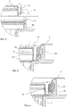
- the clamping ring assembled in accordance with Figure 2 is shown in Figure 3 , installed in a floor drain 2 known per se.
- the floor drain conventionally comprises a drainage aperture 4 leading to a bowl-like body 3, whereby the body additionally has at least a drain trap 5 and an outlet connection 6 to lead the wastewater led to the floor drain further to a sewage system of the premises.
- the body may comprise one or more side inlets to guide wastewater from a sink and/or washing machine, for instance, to the floor drain. These inlets or the sewage system known per se are not separately shown in the attached drawings.
- the clamping ring 1 according to Figure 1 is thus intended, in particular, to attach a sealing layer 7 to a floor drain 2 or a special extension ring (not shown) adapted to it. Obviously, there is nothing to prevent the use of this clamping ring to seal any floor or wall duct and a sealing layer installed on it against each other.
- Such a sealing layer may be, for example, a sealing flange installed on waterproofing paint, a sealing membrane or a plastic carpet.
- the sealing layer is bent by using work methods known per se in the drainage aperture 4 of the floor drain.
- the waste water led in the floor drain is prevented from getting under the sealing layer surrounding the floor drain by locking the sealing layer 7 by the use of the clamping ring 1 against a collar 8 adjacent to the drainage aperture of the floor drain or the extension ring thereof.
- Such a collar sets on a floor drain arranged in the floor structure so that it is substantially perpendicular to a floor surface 9.
- a mating surface 10 protrudes from the collar, advantageously from the end opposite the floor structure, preventing the clamping ring to be introduced too deep in the body 3.
- the clamping ring has three parts.
- the clamping ring comprises a frame ring 11 and an expansion ring 12 setting against the frame ring.
- a clamping ring seal 13 is arranged between the frame ring and expansion ring coupling thereto.
- the clamping ring seal extends outside an outer mantle of a cylinder formed by the frame ring and expansion ring, whereby its protrusion is adjustable by means of locking means 14, such as screws, mechanically pressing the frame ring and expansion ring against each other.
- locking means 14 such as screws
- clamping ring seal 13 As the clamping ring seal 13 is compressed between the frame ring and expansion ring, it protrudes from the cylindrical outer surface of the clamping ring, enlarging the diameter of the clamping ring seal. At the same time, the clamping ring seal made of elastic material is pressed against the collar of the floor drain, as shown in Figure 6 .
- the frame ring 11 comprises a substantially circular member.
- the member has a face 15 oriented towards the collar 8 of the floor drain 2 or its extension ring, and forming a part of the cylinder outer mantle.
- the frame ring further has a bottom surface 16, which bottom surface, when the frame ring is installed in place in the floor drain, is oriented towards the mating surface 10 protruding from the collar.
- Both the frame ring 11 and expansion ring 12 comprises members 19 and 20 to receive the mechanical locking means. These may include, for example, the perforation that can be seen in Figures 2 and 5 .
- the members receiving the mechanical locking means are placed at intervals along the length of said rings in the corresponding places.
- clamping ring seal 13 When said clamping ring seal 13 is arranged at least partly between the bottom surface 16 and installation surface 17, it may also be provided with members 21 that receive mechanical locking means, to simplify installation.
- the mechanical locking means press both the frame ring 11 and expansion ring 12 against each other, the protrusion of the clamping ring seal outside faces 15 and 18 is achieved.
- the amount of the protrusion may be adjusted, for example, by shaping the faces 15 and 18.
- the frame ring 11 and expansion ring 12 are advantageously made of fibreglass-enforced plastic material, but they may likewise be made of another plastic mixture, metal, or alloy suitable for the purpose.
- the clamping ring seal 13 is advantageously manufactured of a rubber or plastic material having adequate flexibility. As relates to the structure, the frame ring, expansion ring, and clamping ring seal may be solid, but it may also be partly or entirely hollow.
- a pressure ring part 22 present in the clamping ring seal 13 and setting against the faces 15 and 18 may be seen. It is in particular this pressure ring that is adapted to project against the collar 8 of the floor drain as the faces approach each other.
- the faces 15 and 18 sloping against each other that is, by causing a conical recess in the cylindrical part of the outer mantle of the clamping ring 1, the faces that are pressing against each other also achieve a more effective thrust motion, which is exerted on this pressure ring, taking it towards the collar 8.
- the faces orienting against each other are additionally adapted to cause a deformation in the pressure ring, which guides a part of the pressure ring closer to the collar or a sealing ring 23 provided therein, for example.
- the pressure ring 22 surface on the collar side may be provided with a surface profiling that adds to the friction between the pressure ring and collar.
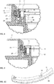
- the pressure ring skirt on the face 18 side may also be formed with a toothing, whereby its deformation, that is, bending towards the collar or, for example, the sealing ring 23 therein is facilitated. Such a toothing is shown in Figure 10 .
- the sealing layer 7 When the sealing layer 7 is installed by the aforementioned embodiment of the present clamping ring 1 to a floor drain 2, for example, the detachment of the sealing layer from the floor drain is prevented by pressing the sealing layer by utilising the clamping ring seal 13 against the collar 8 of the floor drain and/or the sealing ring 23 provided therein, in a manner shown in Figure 4 to 6 , for example.
- the frame ring 11, expansion ring 12, and clamping ring seal 13 with its pressure ring 22 are attached to each other by mechanical locking means 14, as shown in Figure 5 .
- the sealing layer is brought to the duct in a manner known per se, to the drainage aperture of the floor drain, for example, guiding the sealing layer against the collar of the floor drain.
- the clamping ring having a diameter slightly smaller than the diameter of the drainage aperture of the floor drain is pressed into the floor drain.
- the expansion ring pressed into the floor drain advantageously sets against the mating surface 10 in the floor drain while the clamping ring is pressing the sealing layer towards the collar, cf. Figure 6 .
- the frame ring 11 is pressed against the expansion ring 12 by tightening the mechanical locking means 14. Due to the compression, the protrusion of the pressure ring 22 in the clamping ring seal 13 from the cylindrical outer surface of the clamping ring is increased, and the clamping ring seal is pressed against the collar of the floor drain and/or the sealing ring therein.
- a similar working order is utilised when another joint between a duct of a floor or wall and the sealing layer 7 is sealed by pressing the sealing layer against the wall 8 of the duct, such a wall corresponding to the collar of a floor drain as described in the above.
- a second preferred embodiment of the clamping ring 1 comprises two parts partly guided within each other, as shown in Figure 7 .
- Such a clamping ring is hereby formed of the frame ring 11 and expansion ring 12 setting on this frame ring, and the clamping ring seal 13 installed on their outer periphery.
- the frame ring and expansion ring are connected by means of locking means 14, such as screws, mechanically pressing them towards each other.
- both the frame ring and expansion ring have members 19 and 20 to receive the mechanical locking means. These may include, for example, a perforation.
- the members receiving the mechanical locking means are placed at intervals along the length of said rings in the corresponding places.
- These members receiving the locking means are realised so that the members 19 in the frame ring are larger than the locking means, allowing free movement of the locking means in the direction of their longitudinal axis.
- the locking means in the expansion ring are arranged to grab the members 20, whereby the locking means pull the expansion ring against the frame ring.
- the frame ring 11 and expansion ring 12 comprise a base part, from which substantially parallel cylinder means 24 and 25 protrude.
- these cylindrical means set within each other when the frame ring and expansion ring are connected to each other.
- the cylindrical means also define between them a groove 26 in which said clamping ring seal 13 may be arranged.
- the clamping ring seal expands whereby it protrudes and increases the diameter of the clamping ring towards the collar 8 of the floor drain and/or against the sealing ring 23 therein.
- the amount of the protrusion may be adjusted by material selection of the clamping ring seal as well as by selecting different thicknesses for it.
- the third preferred embodiment of the clamping ring 1 comprises two parts partly guidable within each other, as shown in Figures 8 and 9 . Therefore, such a clamping ring is formed exclusively of the frame ring 11 and the expansion ring 12 setting on this frame ring.
- the frame ring and expansion ring are connected by means of locking means 14, such as screws, mechanically pressing them towards each other.
- both the frame ring and expansion ring have members 19 and 20 to receive the mechanical locking means. These may include, for example, the perforation that can be seen in Figures 7 and 8 .
- the members receiving the mechanical locking means are placed at intervals along the length of said rings in the corresponding places.
- These members receiving the locking means are realised so that the members 19 in the frame ring are larger than the locking means, allowing free movement of the locking means in the direction of their longitudinal axis.
- the locking means in the expansion ring are arranged to grab the members 20, whereby the locking means pull the expansion ring against the frame ring.
- the frame ring 11 comprises a substantially circular member.
- the member has a face 15 oriented towards the collar 8 of the floor drain 2 or its extension ring, and forming a part of the cylinder outer mantle.
- the frame ring has a narrowish cylinder part 27 protruding from it in its operational position towards the expansion ring 12, which cylinder part is in its operational position arranged to press by its lower edge against the expansion ring 12 positioned under the frame ring.
- the grip may be further enhanced by arranging a lip 29 at the bottom edge of the cylinder part 27, which presses against the collar 8 or cooperates with the sealing ring 23 in the collar.
- the deformation taking place may in turn be further enhanced by arranging a web 30 in the cylinder part encircling it. Because the material strength of the cylinder part is weaker at such a web, the deformation caused by the compression of the cylindrical surface and directed towards the collar is with a lesser use of force.
- the skirt of the cylinder part 24 on the cylindrical surface 18 side may also be formed toothed or grooved, whereby its deformation, that is, bending towards the collar or the sealing ring 23 therein, is facilitated.
- Such a toothing is shown in Figures 10 and 11.
- the cooperation between the frame ring 11 and expansion ring 12 may be ensured by forming a flange 31 on the expansion ring, which protrudes towards the frame ring and encircles the expansion ring. As shown in Figures 8 and 9 , this flange is arranged to be guided inside the cylinder part 27 of the frame ring as the parts of the clamping ring are connected to each other. When the locking means 14 are being tightened, the cylinder part will thus slide along the flange, hitting the cylindrical surface 28 whereby the outer tip of the cylinder surface is forced in a radial direction towards the collar 8 of the floor drain.
- the sealing layer 7 When the sealing layer 7 is installed by the clamping ring 1 according to the second embodiment present to a floor drain 2, the detachment of the sealing layer from the floor drain is prevented by pressing the sealing layer against the collar 8 of the floor drain and/or the sealing ring 23 present therein, in a manner shown in Figures 7 and 8 .
- the work progresses so that first the frame ring 11 and expansion ring 12 are joined by mechanical locking means 14.
- the clamping ring at this stage has a diameter that is slightly smaller than the diameter of the drainage aperture of the floor drain.
- the clamping ring is pressed into the floor drain and against the sealing layer applied thereto, in a manner known per se.
- a similar working order is utilised when another joint between a duct of a floor or wall and the sealing layer 7 is sealed by pressing the sealing layer against the wall 8 of the duct, such a wall corresponding to the collar of a floor drain as described in the above.
Landscapes
- Engineering & Computer Science (AREA)
- General Engineering & Computer Science (AREA)
- Water Supply & Treatment (AREA)
- Health & Medical Sciences (AREA)
- Life Sciences & Earth Sciences (AREA)
- Hydrology & Water Resources (AREA)
- Public Health (AREA)
- Mechanical Engineering (AREA)
- Structural Engineering (AREA)
- Environmental & Geological Engineering (AREA)
- Civil Engineering (AREA)
- Architecture (AREA)
- Sink And Installation For Waste Water (AREA)
- Gasket Seals (AREA)
- Clamps And Clips (AREA)
Applications Claiming Priority (1)
| Application Number | Priority Date | Filing Date | Title |
|---|---|---|---|
| FI20185499A FI129847B (fi) | 2018-05-31 | 2018-05-31 | Menetelmä vesieristeen tiivistämiseksi läpiviennin reunaa vasten ja siinä käytettävä kiilarengas |
Publications (1)
| Publication Number | Publication Date |
|---|---|
| EP3575656A1 true EP3575656A1 (fr) | 2019-12-04 |
Family
ID=67402786
Family Applications (1)
| Application Number | Title | Priority Date | Filing Date |
|---|---|---|---|
| EP19177249.0A Pending EP3575656A1 (fr) | 2018-05-31 | 2019-05-29 | Procédé de scellement d'une couche isolante contre le bord d'un trou traversant et bague à coin utilisée en son sein |
Country Status (2)
| Country | Link |
|---|---|
| EP (1) | EP3575656A1 (fr) |
| FI (1) | FI129847B (fr) |
Citations (4)
| Publication number | Priority date | Publication date | Assignee | Title |
|---|---|---|---|---|
| DE2147489A1 (de) * | 1971-09-23 | 1973-03-29 | Dornier Ag | Flanschfreie, selbsthaltende durchfuehrungsdichtung |
| WO1980001701A1 (fr) * | 1979-02-09 | 1980-08-21 | G Soederstroem | Liaison de sol pour egout |
| EP0838623A1 (fr) * | 1996-10-24 | 1998-04-29 | Hermann-Heinz Burger Gas- und Wasserarmaturen GmbH | Fermeture à bague de pression |
| DE202005008176U1 (de) * | 2005-05-20 | 2006-09-28 | Doyma Gmbh & Co | Dichtungsvorrichtung mit Keilflächen |
-
2018
- 2018-05-31 FI FI20185499A patent/FI129847B/fi active IP Right Grant
-
2019
- 2019-05-29 EP EP19177249.0A patent/EP3575656A1/fr active Pending
Patent Citations (4)
| Publication number | Priority date | Publication date | Assignee | Title |
|---|---|---|---|---|
| DE2147489A1 (de) * | 1971-09-23 | 1973-03-29 | Dornier Ag | Flanschfreie, selbsthaltende durchfuehrungsdichtung |
| WO1980001701A1 (fr) * | 1979-02-09 | 1980-08-21 | G Soederstroem | Liaison de sol pour egout |
| EP0838623A1 (fr) * | 1996-10-24 | 1998-04-29 | Hermann-Heinz Burger Gas- und Wasserarmaturen GmbH | Fermeture à bague de pression |
| DE202005008176U1 (de) * | 2005-05-20 | 2006-09-28 | Doyma Gmbh & Co | Dichtungsvorrichtung mit Keilflächen |
Also Published As
| Publication number | Publication date |
|---|---|
| FI20185499A1 (fi) | 2019-12-01 |
| FI129847B (fi) | 2022-09-30 |
Similar Documents
| Publication | Publication Date | Title |
|---|---|---|
| CA2255331C (fr) | Raccordement presse fixe entre un raccord et l'extremite d'un tuyau metallique | |
| US7374210B2 (en) | Hydro penetration prevention sleeve | |
| EP3575656A1 (fr) | Procédé de scellement d'une couche isolante contre le bord d'un trou traversant et bague à coin utilisée en son sein | |
| MX2013004506A (es) | Elemento, preferentemente elemento de cierre. | |
| US6739597B2 (en) | Drain Gasket | |
| JP2000199584A (ja) | 壁貫通配管の壁貫通構造及び壁貫通配管の壁通し具 | |
| US10858835B2 (en) | Sealing ring and assembly of ducts including said ring | |
| JPH08277538A (ja) | 取付管の接続継手 | |
| JP6086209B2 (ja) | 排水管接続部材 | |
| KR101914713B1 (ko) | 배수설비 하수관로의 폐공캡 | |
| JP4082550B2 (ja) | マンホール用可撓継手の取付構造及びマンホール用可撓継手 | |
| EP2100070B1 (fr) | Ensemble raccord pour le raccordement d'un branchement cylindrique d'un tuyau en matiere plastique, et procede pour la fixation d'un branchement cylindrique sur un tuyau en matiere plastique | |
| JP3663521B2 (ja) | 地盤埋設用アンカーの頭部シール構造 | |
| JP4827171B2 (ja) | 管用栓を用いた管端閉塞工法 | |
| JP4851901B2 (ja) | 建物の排水管配管構造および該配管構造の施工方法 | |
| KR101972929B1 (ko) | 관로 밀폐 장치 및 이를 이용한 시공방법 | |
| JP2737049B2 (ja) | 地下構造物の躯体と管材との連結方法及び連結構造 | |
| KR102299817B1 (ko) | 하수도 가지관용 고정링 및 이를 포함하는 하수도 가지관 연결구 | |
| JPH1089562A (ja) | 管継手 | |
| FI76163B (fi) | Golvbrunn. | |
| EP3953633B1 (fr) | Ensemble d'étanchéité | |
| KR102181963B1 (ko) | 방수 앵커 및 이를 이용하는 터널 방수공법 | |
| KR102899668B1 (ko) | 내부 삽입식 연결소켓을 포함하는 빗물받이 매립형 연결구 및 이를 포함하는 빗물받이, 그리고 이의 제조방법 | |
| JP6177716B2 (ja) | マンホールに接続する下水道本管の取付装置 | |
| CN222525456U (zh) | 一种螺栓预紧机构 |
Legal Events
| Date | Code | Title | Description |
|---|---|---|---|
| PUAI | Public reference made under article 153(3) epc to a published international application that has entered the european phase |
Free format text: ORIGINAL CODE: 0009012 |
|
| STAA | Information on the status of an ep patent application or granted ep patent |
Free format text: STATUS: THE APPLICATION HAS BEEN PUBLISHED |
|
| AK | Designated contracting states |
Kind code of ref document: A1 Designated state(s): AL AT BE BG CH CY CZ DE DK EE ES FI FR GB GR HR HU IE IS IT LI LT LU LV MC MK MT NL NO PL PT RO RS SE SI SK SM TR |
|
| AX | Request for extension of the european patent |
Extension state: BA ME |
|
| STAA | Information on the status of an ep patent application or granted ep patent |
Free format text: STATUS: REQUEST FOR EXAMINATION WAS MADE |
|
| 17P | Request for examination filed |
Effective date: 20200602 |
|
| RBV | Designated contracting states (corrected) |
Designated state(s): AL AT BE BG CH CY CZ DE DK EE ES FI FR GB GR HR HU IE IS IT LI LT LU LV MC MK MT NL NO PL PT RO RS SE SI SK SM TR |
|
| STAA | Information on the status of an ep patent application or granted ep patent |
Free format text: STATUS: EXAMINATION IS IN PROGRESS |
|
| 17Q | First examination report despatched |
Effective date: 20220105 |
|
| GRAP | Despatch of communication of intention to grant a patent |
Free format text: ORIGINAL CODE: EPIDOSNIGR1 |
|
| STAA | Information on the status of an ep patent application or granted ep patent |
Free format text: STATUS: GRANT OF PATENT IS INTENDED |
|
| RIC1 | Information provided on ipc code assigned before grant |
Ipc: F16L 5/08 20060101AFI20260126BHEP Ipc: F16J 15/02 20060101ALN20260126BHEP Ipc: E03F 5/04 20060101ALN20260126BHEP |
|
| INTG | Intention to grant announced |
Effective date: 20260205 |