EP3575697A1 - Deckenklimaanlage und steuerungsverfahren dafür - Google Patents
Deckenklimaanlage und steuerungsverfahren dafür Download PDFInfo
- Publication number
- EP3575697A1 EP3575697A1 EP19177603.8A EP19177603A EP3575697A1 EP 3575697 A1 EP3575697 A1 EP 3575697A1 EP 19177603 A EP19177603 A EP 19177603A EP 3575697 A1 EP3575697 A1 EP 3575697A1
- Authority
- EP
- European Patent Office
- Prior art keywords
- discharge vane
- angle
- discharge
- angle group
- vane
- Prior art date
- Legal status (The legal status is an assumption and is not a legal conclusion. Google has not performed a legal analysis and makes no representation as to the accuracy of the status listed.)
- Granted
Links
Images




Classifications
-
- F—MECHANICAL ENGINEERING; LIGHTING; HEATING; WEAPONS; BLASTING
- F24—HEATING; RANGES; VENTILATING
- F24F—AIR-CONDITIONING; AIR-HUMIDIFICATION; VENTILATION; USE OF AIR CURRENTS FOR SCREENING
- F24F1/00—Room units for air-conditioning, e.g. separate or self-contained units or units receiving primary air from a central station
- F24F1/0007—Indoor units, e.g. fan coil units
- F24F1/0011—Indoor units, e.g. fan coil units characterised by air outlets
- F24F1/0014—Indoor units, e.g. fan coil units characterised by air outlets having two or more outlet openings
-
- F—MECHANICAL ENGINEERING; LIGHTING; HEATING; WEAPONS; BLASTING
- F24—HEATING; RANGES; VENTILATING
- F24F—AIR-CONDITIONING; AIR-HUMIDIFICATION; VENTILATION; USE OF AIR CURRENTS FOR SCREENING
- F24F13/00—Details common to, or for air-conditioning, air-humidification, ventilation or use of air currents for screening
- F24F13/08—Air-flow control members, e.g. louvres, grilles, flaps or guide plates
- F24F13/10—Air-flow control members, e.g. louvres, grilles, flaps or guide plates movable, e.g. dampers
-
- F—MECHANICAL ENGINEERING; LIGHTING; HEATING; WEAPONS; BLASTING
- F24—HEATING; RANGES; VENTILATING
- F24F—AIR-CONDITIONING; AIR-HUMIDIFICATION; VENTILATION; USE OF AIR CURRENTS FOR SCREENING
- F24F1/00—Room units for air-conditioning, e.g. separate or self-contained units or units receiving primary air from a central station
- F24F1/0007—Indoor units, e.g. fan coil units
- F24F1/0011—Indoor units, e.g. fan coil units characterised by air outlets
-
- F—MECHANICAL ENGINEERING; LIGHTING; HEATING; WEAPONS; BLASTING
- F24—HEATING; RANGES; VENTILATING
- F24F—AIR-CONDITIONING; AIR-HUMIDIFICATION; VENTILATION; USE OF AIR CURRENTS FOR SCREENING
- F24F1/00—Room units for air-conditioning, e.g. separate or self-contained units or units receiving primary air from a central station
- F24F1/0007—Indoor units, e.g. fan coil units
- F24F1/0043—Indoor units, e.g. fan coil units characterised by mounting arrangements
- F24F1/0047—Indoor units, e.g. fan coil units characterised by mounting arrangements mounted in the ceiling or at the ceiling
-
- F—MECHANICAL ENGINEERING; LIGHTING; HEATING; WEAPONS; BLASTING
- F24—HEATING; RANGES; VENTILATING
- F24F—AIR-CONDITIONING; AIR-HUMIDIFICATION; VENTILATION; USE OF AIR CURRENTS FOR SCREENING
- F24F11/00—Control or safety arrangements
- F24F11/70—Control systems characterised by their outputs; Constructional details thereof
- F24F11/72—Control systems characterised by their outputs; Constructional details thereof for controlling the supply of treated air, e.g. its pressure
- F24F11/79—Control systems characterised by their outputs; Constructional details thereof for controlling the supply of treated air, e.g. its pressure for controlling the direction of the supplied air
-
- F—MECHANICAL ENGINEERING; LIGHTING; HEATING; WEAPONS; BLASTING
- F24—HEATING; RANGES; VENTILATING
- F24F—AIR-CONDITIONING; AIR-HUMIDIFICATION; VENTILATION; USE OF AIR CURRENTS FOR SCREENING
- F24F13/00—Details common to, or for air-conditioning, air-humidification, ventilation or use of air currents for screening
- F24F13/08—Air-flow control members, e.g. louvres, grilles, flaps or guide plates
- F24F13/10—Air-flow control members, e.g. louvres, grilles, flaps or guide plates movable, e.g. dampers
- F24F13/14—Air-flow control members, e.g. louvres, grilles, flaps or guide plates movable, e.g. dampers built up of tilting members, e.g. louvre
- F24F13/1413—Air-flow control members, e.g. louvres, grilles, flaps or guide plates movable, e.g. dampers built up of tilting members, e.g. louvre using more than one tilting member, e.g. with several pivoting blades
-
- F—MECHANICAL ENGINEERING; LIGHTING; HEATING; WEAPONS; BLASTING
- F24—HEATING; RANGES; VENTILATING
- F24F—AIR-CONDITIONING; AIR-HUMIDIFICATION; VENTILATION; USE OF AIR CURRENTS FOR SCREENING
- F24F13/00—Details common to, or for air-conditioning, air-humidification, ventilation or use of air currents for screening
- F24F13/02—Ducting arrangements
- F24F13/06—Outlets for directing or distributing air into rooms or spaces, e.g. ceiling air diffuser
- F24F13/072—Outlets for directing or distributing air into rooms or spaces, e.g. ceiling air diffuser of elongated shape, e.g. between ceiling panels
Definitions
- the present invention relates to a ceiling type air conditioner and a method of controlling the same.
- An air conditioner is an apparatus for maintaining air of a predetermined space in a best state according to usage or purposes thereof.
- the air conditioner includes a compressor, a condenser, an expansion device and an evaporator.
- a freezing cycle for performing compression, condensation, expansion and evaporation of refrigerant may be performed to cool or heat the predetermined space.
- the predetermined space may be changed according to place where the air conditioner is used. For example, when the air conditioner is positioned in home or office, the predetermined space may be an indoor space of a house or building.
- an outdoor heat exchanger provided in an outdoor unit performs a condensation function and an indoor heat exchanger provided in an indoor unit performs an evaporation function.
- the outdoor heat exchanger performs a condensation function and the indoor heat exchanger performs an evaporation function.
- the air conditioner may be classified into an upright type, a wall-mounted type or a ceiling type according to the installation position thereof.
- the upright type air conditioner refers to an air conditioner standing up in an indoor space
- the wall-mounted type air conditioner refers to an air conditioner attached to a wall surface.
- the ceiling type air conditioner is understood as an air conditioner installed in a ceiling.
- the ceiling type air conditioner includes a casing embedded in a ceiling and a panel coupled to a lower side of the casing and including an inlet and an outlet formed therein.
- discharge airflow of an indoor unit is made similar to natural wind by controlling a speed for rotating upper and lower vanes between a maximum upward angle and a maximum downward angle to a high speed or a low speed according to a set cycle.
- control method disclosed in the related art has a disadvantage in that a time required to decrease or increase an indoor temperature according to cooling/heating operation in a natural wind mode is remarkably increased as compared to a general auto swing mode. As a result, a time required to implement an air conditioning environment in which a user may feel a pleasant feeling is remarkably increased.
- Embodiments provide a method of controlling a ceiling type air conditioner capable of improving a pleasant feeling of a user by providing discharge airflow similar to natural wind.
- Embodiments provide a method of controlling a ceiling type air conditioner capable of enabling an indoor air conditioning environment to rapidly reach an environment set by a user.
- Embodiments provide a method of controlling ceiling type air conditioner capable of relatively uniformly providing a temperature distribution or airflow distribution of an indoor space in which an air conditioner is installed.
- a ceiling type air conditioner includes a panel located on a ceiling surface, outlets formed to correspond to four sides of the panel, and first to fourth discharge vanes for opening and closing the outlets.
- each of the first to fourth discharge vanes including an upper discharge vane and a lower discharge vane located below the upper discharge vane and rotating along with the upper discharge vane.
- the method of controlling the ceiling type air conditioner includes performing first operation in which the first discharge vane rotates in a first angle group, the second discharge vane rotates in a second angle group, the third discharge vane rotates in a third angle group and the fourth discharge vane rotates in a fourth angle group, performing second operation in which the first discharge vane rotates in the fourth angle group, the second discharge vane rotates in the first angle group, the third discharge vane rotates in the second angle group and the fourth discharge vane rotates in the third angle group, performing third operation in which the first discharge vane rotates in the third angle group, the second discharge vane rotates in the fourth angle group, the third discharge vane rotates in the first angle group and the fourth discharge vane rotates in the second angle group, and performing fourth operation in which the first discharge vane rotates in the second angle group, the second discharge vane rotates in the third angle group, the third discharge vane rotates in the fourth angle group and the fourth discharge vane rotates in the first angle group.
- first to the fourth angle groups may be set such that rotation angles of the discharge vanes have different ranges.
- first to fourth discharge vanes may guide discharged air to relatively closest to the ceiling surface when rotating in the first angle group, and guide discharged air to relatively closest to an indoor floor surface when rotating in the fourth angle group.
- the first to fourth operations may be performed for a set time.
- the first angle group may include a smallest rotation angle of the upper discharge vane and a smallest rotation angle of the lower discharge vane.
- the fourth angle group may include a largest rotation angle of the upper discharge vane and a largest rotation angle of the lower discharge vane.
- a range of a rotation angle of the upper discharge vane may be less than a range of a rotation angle of the lower discharge vane.
- a rotation angle of the upper discharge vane may be set to 58° or more and less than 71°, and a rotation angle of the lower discharge vane may be set to 15° or more and less than 45°.
- a rotation angle of the upper discharge vane may be set to 64° or more and less than 72°, and a rotation angle of the lower discharge vane may be set to 25° or more and less than 55°.
- a rotation angle of the upper discharge vane may be set to 68° or more and less than 73°, and a rotation angle of the lower discharge vane may be set to 35° or more and less than 64°.
- a rotation angle of the upper discharge vane may be set to 71° or more and less than 74°, and a rotation angle of the lower discharge vane may be set to 45° or more and less than 72°.
- a ceiling type air conditioner in another aspect, includes a panel located on a ceiling surface, outlets formed to correspond to four sides of the panel, discharge vanes provided on the four outlets and each including an upper discharge vane and a lower discharge vane located below the upper discharge vane and rotating along with the upper discharge vane, and a controller configured to control rotation angles of the discharge vanes.
- the controller may control a first discharge vane located at any one of the four outlets to follow a first angle group including a smallest rotation angle.
- controller may control a second discharge vane located at a position rotated from the first discharge vane clockwise to follow a second angle group having a rotation angle greater than that of the first angle group.
- controller may control a third discharge vane located at a position rotated from the second discharge vane clockwise to follow a third angle group having a rotation angle greater than that of the second angle group.
- controller may control a fourth discharge vane located at a position rotated from the third discharge vane clockwise to follow a fourth angle group having a rotation angle greater than that of the third angle group.
- controller may control the second to third discharge vanes to sequentially follow the first angle group when a predetermined time has elapsed.
- controller may control the first discharge vane to sequentially rotate in the second to fourth angle groups as a predetermined has elapsed.
- controller may count the number of cycles in which the first discharge vane rotates in the first to fourth angle groups.
- controller may repeatedly control the first discharge vane to rotate in the first angle group when the counted number of cycles is less than a predetermined number of cycles.
- the present invention has the following effects.
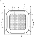
- FIG. 1 is bottom view showing the configuration of a ceiling type air conditioner according to an embodiment of the present invention
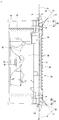
- FIG. 2 is a cross-sectional view taken along line I-I' of FIG. 1 .
- the ceiling type air conditioner 10 (hereinafter referred to as an air conditioner) according to the embodiment of the present invention includes a casing 50 and a panel 20.
- the casing 50 is embedded in the internal space of a ceiling and the panel 20 is substantially located at a height of the ceiling to be exposed to the outside.
- a plurality of parts may be installed in the casing 50.
- the plurality of parts includes a heat exchanger 70 for exchanging heat with air sucked into the casing 50.
- the heat exchanger 70 may be disposed to be bent multiple times along the inner surface of the casing 50 and to surround a fan 60.
- the plurality of parts further includes a fan 60 driven for suction and discharge of indoor air and an air guide 68 for guiding air sucked toward the fan 60.
- the fan 60 is coupled with a motor shaft 66 of a fan motor 65.
- the fan 60 may rotate by driving the fan motor 65.
- the air guide 68 is disposed at the suction side of the fan 60 to guide air sucked through an inlet 34 toward the fan 60.
- the fan 60 may include a centrifugal fan.
- the panel 20 is mounted on the lower end of the casing 50 and may be substantially formed in a rectangular shape when viewed from the lower side thereof.
- the panel 20 may be formed to protrude outward from the lower end of the casing 50 and a circumference thereof may be in contact with a lower surface (ceiling surface) of the ceiling.
- the panel 20 includes a panel body 21 and outlets 22, through which air of the internal space of the casing 50 is discharged.
- the outlets 22 may be formed by perforating at least a portion of the panel body 21 and may be formed at positions corresponding to four sides of the panel body 21.
- the outlets 22 may be formed along the extension directions of the four sides of the panel 20.
- the extension direction may be understood as the longitudinal direction of one of the four sides of the panel 20.
- the direction perpendicular to the longitudinal direction may be understood as a width direction.
- the air conditioner 10 further includes discharge vanes 81, 82, 83 and 84 for opening and closing the outlets 22 and a discharge motor 90 for rotating the discharge vanes.
- the discharge vanes 81, 82, 83 and 84 may be mounted in the panel 20.
- the discharge vanes 81, 82, 83 and 84 may be formed in a shape corresponding to the opening shape of the outlet 22. Accordingly, the discharge vanes 81, 82, 83 and 84 may open or close the outlets 22 formed at the four sides of the panel 20.
- discharge vanes 81, 82, 83 and 84 are provided with two dual guide portions 81a, 83a, 81b and 83b for guiding the discharge direction of air passing through the internal space of the casing 50.
- the dual guide portions are disposed to be spaced apart from each other in the upward-and-downward direction or in the inward-and-outward direction.
- the discharge vanes 81, 82, 83 and 84 may guide air discharged into the indoor space, in which the air conditioner 10 is installed, in directions according to two angles.
- the discharged air can reach up to a longer distance.
- the upper guide portions of the dual guide portions are defined as upper discharge vanes 81a and 83a and the lower guide portions thereof are defined as lower discharge vanes 81b and 83b.
- the discharge vanes 81, 82, 83 and 84 include the upper discharge vanes 81a and 83a and the lower discharge vanes 81b and 83b for guiding the discharged air at set angles.
- the upper discharge vanes 81a and 83a are disposed at the upstream side or inside of the lower discharge vanes 81b and 83b. Accordingly, the upper discharge vanes 81a and 83a may also be referred to as internal vanes.
- the lower discharge vanes 81b and 83b may be downstream side or outside of the upper discharge vanes 81a and 83a. Accordingly, the lower discharge vanes 81b and 83b may also be referred to as external vanes.
- the upper discharge vanes 81a and 83a and the lower discharge vanes 81b and 83b may guide the discharged air at different angles. That is, the direction of the discharged air guided by the upper discharge vanes 81a and 83a and the direction of the discharge air guided by the lower discharge vanes 81b and 83b may be different.
- air discharged from the upper discharge vanes 81a and 83a may be discharged to the upper side of the indoor space than air discharged from the lower discharge vanes 81b and 83b.
- the lower discharge vanes 81b and 83b may be formed to have a larger area of an air guide surface than the upper discharge vanes 81a and 83a. That is, the lower discharge vanes 81b and 83b may extend to have a greater width than the upper discharge vanes 81a and 83a.
- the lower discharge vanes 81b and 83b may be formed to have a larger length than the upper discharge vanes 81a and 83a in the discharge direction of air.
- air discharged from the lower discharge vanes 81b and 83b may reach a farther position than air discharged from the upper discharge vanes 81a and 83a. Accordingly, in particular, in the heating operation, the discharged air guided by the lower discharge vanes 81b and 83b flows in a relatively long distance, thereby providing warm air to the floor surface.
- the air discharged by the upper discharge vanes 81a and 83a and the lower discharge vanes 81b and 83b form swirling airflow by a wind speed, density, a temperature difference, thereby facilitating mixing of indoor air. Therefore, the indoor temperature can rapidly increase in the heating operation.
- the upper discharge vanes 81a and 83a and the lower discharge vanes 81b and 83b may extend to form a curved surface toward the air discharge direction.
- the discharge vanes 81, 82, 83 and 84 include a first discharge vane 81, a second discharge vane 82, a third discharge vane 83 and a fourth discharge vane 84 capable of opening and closing the outlets 22 formed along the four sides of the panel 20.
- Each of the first to fourth discharge vanes 80 includes the upper discharge vanes 81a and 83a and the lower discharge vanes 81b and 83b. That is, each of the first to fourth discharge vanes 80 includes dual guide portions.
- the first discharge vane 81 includes the upper discharge vane 81a and the lower discharge vane 81b.
- the third discharge vane 83 includes the upper discharge vane 83a and the lower discharge vane 83b.
- each of the second discharge vane 82 and the fourth discharge vane 84 includes the upper discharge vane and the lower discharge vane.
- the first discharge vane 81 and the third discharge vane 83 are positioned in directions opposite to each other.
- the second discharge vane 82 and the fourth discharge vane 84 are positioned in directions opposite to each other.
- the first vane 81 and the third discharge vane 83 may be positioned perpendicular to the second discharge vane 82 and the fourth discharge vane 84.
- the first discharge vane 81 is spaced apart from the third discharge vane 83 in a horizontal direction and the second discharge vane 82 is spaced apart from the fourth discharge vane 83 in a vertical direction. That is, the first discharge vane 81 and the third discharge vane 83 are provided to open and close the outlets 22 formed in the vertical direction and the second discharge vane 82 and the fourth discharge vane 84 are provided to open and close the outlets 22 formed in the horizontal direction.
- a virtual horizontal line parallel to the ground forming a horizontal surface or a ceiling surface, on which the panel 20 is mounted, and passing through the rotation center of the third discharge vane 83 and the rotation center of the first discharge vane 81 is defined as a horizontal reference line h.
- the rotation angle of the upper discharge vane or the lower discharge vane may be determined.
- virtual straight lines drawn along the width direction of the discharge vane 80 that is, the longitudinal section of the discharge vane 80, are defined as extension lines L1 and S1.
- the extension lines include the upper extension line S1 which is the virtual straight line drawn along the longitudinal sections of the upper discharge vanes 81a and 83a and the lower extension line L1 which is the virtual straight line drawn along the longitudinal sections of the lower discharge vanes 81b and 83b.
- an angle a between the horizontal reference line h and the upper extension line S1 may be understood as the rotation angles of the upper discharge vanes 81a and 83a
- an angle b between the horizontal reference line h and the lower extension line L1 may be understood as the rotation angles of the upper discharge vanes 81b and 83b.
- the rotation angle of the upper discharge vanes of the second discharge vane 82 and the fourth discharge vane 84 may be defined as the first rotation angle a and the rotation angle of the lower discharge vanes of the second vane groups 82 and 84 may be defined as the second rotation angle b.
- the angle between the horizontal reference line h and extension lines S1 of the upper discharge vanes 81a and 83a is referred to as a first rotation angle a and the angle between the horizontal reference line h and the extension lines L1 of the lower discharge vanes 81b and 83b is referred to as a second rotation angle b.
- angles a between the horizontal reference line h and the extension lines S1 of the upper discharge vanes 81a and 83a may be different.
- angles b between the horizontal reference line h and the extension lines L1 of the upper discharge vanes 81b and 83b may be different. This will be described below.
- the rotation range of the upper discharge vanes 81a and 83a may be less than that of the lower discharge vanes 81b and 83b.
- the range of the first rotation angle a may be less than that of the second rotation angle b.
- the range of the first rotation angle a may be set to 58° to 74°
- the range of the second rotation angle b may be set to 15° to 74°.
- the discharge motor 90 may be connected to the discharge vanes 81, 82, 83 and 84 to provide power. In addition, the discharge motor 90 may rotate the discharge vane 80 and the outlets 22 may be opened and closed by rotation of the discharge vane 80. For example, a plurality of discharge motors 90 may be provided to be connected to the discharge vanes 81, 82, 83 and 84.
- the discharge motor 90 may include a step motor.
- a suction grill 30 is mounted at the center of the panel 20.
- the suction grill 30 forms the lower appearance of the air conditioner 10 and has a substantially rectangular frame shape.
- the suction grill 30 includes a grill body 32 having a grid shape and including an inlet 34.
- a filter member 36 for filtering air sucked through the inlet 34 is provided on the grill body 32.
- the filter member 36 may have a substantially rectangular frame shape.
- the outlets 22 may be disposed outside the suction grill 30 in four directions.
- the outlets 22 may be provided outside the inlet 34 in the up, down, left and right directions.
- Cover mounting portions 27 are formed at four corners of the panel body 21.
- the cover mounting portions 27 may be formed by perforating at least a portion of the panel body 21.
- the cover mounting portions 27 are used to check the services of the plurality of parts mounted on the rear surface of the panel 20 or operation of the air conditioner 10 and may be configured to be opened or closed by the cover member 40.
- Air flow in the air conditioner 10 will be briefly described.
- the fan motor 65 is driven to generate rotation force in the fan 60, air of the indoor space is sucked through the inlet 34 and is filtered by the filter member 36.
- the sucked air flows to the fan 60 through the inner space of the air guide 68 and the flow direction of air is changed through the fan 60.
- the upper discharge vanes 81a and 83a and the lower discharge vanes 81b and 83b are linked by a plurality of links to rotate. Therefore, the upper discharge vanes 81a and 83a and the lower discharge vanes 81b and 83b rotate by one discharge motor 90.
- FIG. 3 is a partial enlarged view of "A" of FIG. 2 .
- FIG. 3 shows the connection state and rotation operation of the upper discharge vane 81a and the lower discharge vane 81b based on the first discharge vane 81.
- first discharge vane 81 to the fourth discharge vane 84 are different from each other in arrangement or formation position but are equal to each other in the configuration, for the upper discharge vanes and the lower discharge vanes of the second discharge vane 82, the third discharge vane 83 and the fourth discharge vane 84, refer to the description of the upper discharge vane 81a and the lower discharge vane 81b of the first discharge vane 81.
- the air conditioner 10 further includes a motor connector 91 coupled with the discharge motor 90, a rotation link 92 connected with the discharge motor 90 coupled to the motor connector 91 and capable of rotating, and a slave link 93 coupled to one end of the rotation link 92 to guide rotation of the upper discharge vane 81a.
- the motor connector 91 may be provided inside the panel 20.
- the motor connector 91 may be located on the inner surface of the panel body 21 in which the outlet 22 is formed.
- the motor connector 91 may be coupled with the discharge motor 90 at one side thereof.
- the rotation shaft of the discharge motor 90 may extend in the direction of the outlet 22 through the motor connector 91.
- the rotation shaft of the discharge motor 90 may be coupled to the rotation center 92a of the rotation link 92. Accordingly, the rotation link 92 may rotate about the rotation center 92a according to rotation of the discharge motor 90.
- the motor connector 91 includes a stop projection 91c for restricting rotation of the rotation link 92.
- the stop projection 91c may be formed to protrude in the direction of the outlet 22 along a portion of the circumference of the motor connector 91.
- the stop projection 91c may restrict rotation of the rotation link 92 when the lower discharge vane 81b reaches a position where the outlet 22 is closed, such that the lower discharge vane 81b no longer rotates.
- the rotation link 92 may be coupled to the rotation shaft of the discharge motor 90 at the rotation center 92a. Accordingly, the rotation link 92 may rotate clockwise or counterclockwise with respect to the rotation center 92a by rotation of the discharge motor 90.
- a first rotation shaft 92b coupled with the slave link 93 is formed on one end of the rotation link 92, and a second rotation shaft 92c coupled with the lower discharge vane 81b is formed on the other end of the rotation link 92.
- the second rotation shaft 92c rotates according to rotation of the discharge motor 90 (see an arrow), and thus the lower discharge vane 81b receives force and rotates in the upward-and-downward direction to open and close the outlet 22.
- the second rotation shaft 92c is coupled to one end of the lower discharge vane 81b. At this time, the second rotation shaft 92c is coupled with an upstream end for guiding discharged air.
- the lower discharge vane 81b may be connected to the panel 20 by a second fixing shaft 96.
- the second fixing shaft 96 may be formed at one side of the panel 20 to extend toward the outlet 22.
- a guide link 94 rotatably coupled to the second fixing shaft 96 may be connected to the center of the lower discharge vane 81b to guide upward and downward rotation of the lower discharge vane 81b.
- the guide link 94 may be coupled to the lower discharge vane 81b at the downstream side of the second rotation shaft 92c in the air discharge direction.
- the lower discharge vane 81b may rotate to open and close the outlet 22 according to rotation of the rotation link 92.
- the second rotation angle b of the lower discharge vane 81b may be determined according to the rotation degree of the rotation link 92, that is, the rotation angle of the discharge motor 90.
- the first rotation shaft 92b rotates according to rotation of the discharge motor 90 (see an arrow) and thus the slave link 93 coupled to the first rotation shaft 92b rotates, thereby guiding rotation of the upper discharge vane 81a.
- the slave link 93 may move according to rotation of the first rotation shaft 92b such that the upper discharge vane 81a rotates upward or downward.
- a hole for coupling of the first rotation shaft 92b is formed in one side of the slave link 93 and a protrusion for coupling to the upper discharge vane 81b is formed on the other side of the slave link 93.
- the upper discharge vane 81a is coupled to be fixed to the panel 20 by the first fixing shaft 95 and the first fixing shaft 95 becomes the rotation center of the upper discharge vane 81a. Accordingly, the upper discharge vane 81a may rotate about the first fixing shaft 95 in the upward-and-downward direction by force received from the slave link 93.
- the upper discharge vane 81a may rotate according to rotation of the rotation link 92.
- the first rotation angle a of the upper discharge vane 81b may be determined according to the rotation degree of the rotation link 92, that is, the rotation angle of the discharge motor 90.
- the upper discharge vane 81a Since the width of the upper discharge vane 81a located inside the outlet 22 is less than that of the lower discharge vane 81b, the upper discharge vane 81a needs to minimize flow resistance against the discharged air and to secure the rotation angle. Accordingly, the upper discharge vane 81a is not directly coupled to the rotation link 92 but is connected to the rotation link 92 through the slave link 93.
- the rotation link 92 may be formed such that a distance r1 from the rotation center 92a to the first rotation shaft 92b is less than a distance r2 from the rotation center 91c to the second rotation shaft 92c.
- the rotation link 92 may be formed such that a length from the rotation center 92c to the slave link 93 is greater than a length from the rotation center 92c to the lower discharge vanes 81b and 83b.
- the rotation link 92 may extend in two directions to form a predetermined angle from the rotation center 92a. That is, the rotation link 92 may be formed as a frame having a " " shape or a " “ shape. At this time, the rotation center 91c may be located at the center of the bending portion of the rotation link 92.
- the distance r1 from the rotation center 91c to the first rotation shaft 92b of the slave link 83 and the distance r2 from the rotation center 91c to the second rotation shaft 92c may be understood as rotation radii.
- the first rotation angle a may be less than the second rotation angle b by rotation of the rotation link 92, as described above.
- the second rotation angle b may be changed to be greater than the first rotation angle a.
- the first rotation angle a may be 4.7° and the second rotation angle b may be 20.5°.
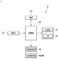
- FIG. 4 is a block diagram showing the configuration of a ceiling type air conditioner according to an embodiment of the present invention.
- the air conditioner 10 further includes a controller 100 for controlling the fan motor 65 and the discharge motor 90.
- the controller 100 may control the fan motor 65 in order to control an air volume or a wind speed. Accordingly, the controller 100 may control rotation of the fan 60 connected to the fan motor 65.
- controller 100 may control rotation of the discharge motor 90.
- the controller 100 may control rotation of the discharge vane 80, that is, the upper discharge vane and the lower discharge vane, by controlling the rotation angle or the rotation direction of the discharge motor 90.
- controller 100 may control the discharge motor 90 connected to the discharge vanes 81, 82, 83 and 84 respectively provided in the outlets 22 corresponding to the four sides of the panel 20.
- the controller 100 may individually control the rotation angles of the first to fourth discharge vanes 81, 82, 83 and 84.
- the upper discharge vane and the lower discharge vane provided in any one of the discharge vanes 81, 82, 83 and 84 may be linked to each other to rotate by rotation of one discharge motor 90. Accordingly, the ranges of the first rotation angle and the second rotation angle b may be determined according to the rotation angle of the discharge motor 90.
- the ranges of the first rotation angle a and the second rotation angle b determined according to the rotation angle range of the discharge motor 90 are defined as a first angle group P1, a second angle group P2, a third angle group P3 and a fourth angle group P4.
- the first to fourth angle groups may be defined as the ranges of the first rotation angle a of the upper discharge vane and the second rotation angle b of the lower discharge vane according to the rotation angle of the discharge motor 90 connected to the discharge vanes 81, 82, 83 and 84.
- the first angle group P1 to the fourth angle group P4 may be defined as ranges having different minimum and maximum angles.
- the first rotation angle a of the first angle group P1 is defined as a range of 58° or more and less than 71° and the second rotation angle b thereof is defined as a range of 15° or more and less than 45°.
- the first rotation angle a of the second angle group P2 is defined as a range of 64° or more and less than 72° and the second rotation angle b thereof is defined as a range of 25° or more and less than 55°.
- the first rotation angle a of the third angle group P3 is defined as a range of 68° or more and less than 73° and the second rotation angle b thereof is defined as a range of 35° or more and less than 64°.
- the first rotation angle a of the fourth angle group P4 is defined as a range of 71° or more and less than 74° and the second rotation angle b thereof is defined as a range of 45° or more and less than 72°.
- the controller 100 may perform control such that the first discharge vane 81 to the fourth discharge vane 84 rotate in any one of the first to fourth angle groups P1, P2, P3 and P4.
- the controller 100 may control the first rotation angle a and second rotation angle b of the first discharge vane 81 to follow the first angle group P1. At the same time, the controller 100 may control the first angle a and second rotation angle b of the second discharge vane 82 to follow the second angle group P2.
- the upper discharge vane and the lower discharge vane provided in each of the discharge vanes 81, 82, 83 and 84 may rotate between a minimum rotation angle and a maximum rotation angle corresponding to any one angle group.
- the upper discharge vane 81a of the first discharge vane 81 may continuously rotate between the minimum rotation angle of 58° and the maximum rotation angle of 71° corresponding to the first angle group P1, and the lower discharge vane 81b thereof may continuously rotate between the minimum rotation angle of 15° and the maximum rotation angle of 45°.
- the first angle group P1 may have the smallest first rotation angle a and second rotation angle b among the first angle group P1 to the fourth angle group P4.
- the discharge vane rotating along the first angle group P1 may guide discharged air in a relatively horizontal direction as compared to the discharge vane rotating in the other angle groups P2, P3 and P4. Accordingly, it is possible to form discharge airflow closest to the indoor ceiling surface.
- the fourth angle group P4 may have largest first rotation angle a and second rotation angle b among the first angle group P1 to the fourth angle group P4.
- the discharge vane rotating along the fourth angle group P4 may guide discharged air in a relatively vertical direction as compared to the discharge vane rotating in the other angle groups P1, P2 and P3. Accordingly, it is possible to form discharge airflow closest to the indoor floor surface.
- discharged air may be guided to form horizontal airflow flowing relatively close to the ceiling surface and then guided to form vertical airflow flowing relatively close to the floor surface.
- the air conditioner 10 further includes a detector 110 capable of detecting a time, a distance, a temperature of an indoor space, and presence/absence of an occupant.
- the detector 110 may include a timer for detecting an operation time, a distance detection sensor provided on the front surface of the panel 20 and a temperature detection sensor for detecting an indoor temperature.
- the temperature detection sensor may detect and transmit the indoor temperature to the controller 100. Accordingly, the controller 100 may determine whether to reach a target temperature set by the user based on the result of detection.
- the air conditioner 10 further includes a memory for storing necessary data.
- the memory 150 may store predetermined information for operation of the air conditioner.
- the controller 100 may transmit and receive data to and from the memory 150. Accordingly, the controller 100 may read and written data from and in the memory 150.
- a natural wind mode of the operation modes of the air conditioner may be defined as an operation mode for enabling the air conditioner for providing cooling or heating simulates the frequency characteristics of airflow formed by natural wind to provide a pleasant feeling capable of being obtained by natural wind to the user in the indoor space.
- the airflow frequency characteristics of natural wind have high energy distribution in a low frequency region and low energy distribution in a high frequency distribution (see FIG. 6A ).
- the natural wind mode of a conventional air conditioner is implemented while changing air volume with time based on an auto swing mode in which rotation angles of all vanes are changed from a minimum angle to a maximum angle.
- the conventional air conditioner for solving such a problem performs control to reduce air volume or to change the rotation angular speed of the discharge vane.
- the guide direction of the discharged air is not formed based on the user, it takes a considerable time to achieve an air conditioning environment set by the user. Therefore, it is difficult to provide a pleasant feeling satisfied by the user.
- the ceiling type air conditioner 10 can maximally simulate the frequency characteristics of natural wind and rapidly improve the pleasant feeling of the user, by forming whirlwind in the natural wind mode.
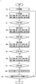
- FIG. 5 is a flowchart illustrating a method of controlling a ceiling type air conditioner according to an embodiment of the present invention.
- the ceiling type air conditioner may enter a natural wind mode when cooling operation or heating operation is provided (S10).
- the controller 100 may receive a signal of the operation unit (not shown) and control the components such as the detector 110, the fan motor 65 and the discharge motor 90 to perform operation set in the natural wind mode.
- the user may input the natural wind mode as the mode of the ceiling type air conditioner 10 through the operation unit (not shown).
- the air conditioner provides relatively warm air in an indoor environment requiring heating and provide relatively cold air in an indoor environment requiring cooling.
- the controller 100 may perform control such that the first discharge vane 81, the second discharge vane 82, the third discharge vane 83 and the fourth discharge vane 84 rotate in different angle groups P1, P2, P3 and P4.
- the first to fourth discharge vanes 81, 82, 83 and 84 guide air while rotating in ranges set in different angle groups, the directions of airflows formed by air discharged in four ways are different.
- the controller 100 may perform control such that the first to fourth discharge vanes 81, 82, 83 and 84 perform first operation (S20).
- the first operation is defined as operation in which the first discharge vane 81 rotates in the first angle group P1, the second discharge vane 82 rotates in the second angle group P2, the third discharge vane 83 rotates in the third angle group P3, and the fourth discharge vane 84 rotates in the fourth angle group P4.
- airflow formed by air discharged through the first discharge vane 81 is formed in an upper horizontal direction relatively close to the ceiling surface
- airflow formed by air discharged through the second discharge vane 82 is formed at a position lower than that of airflow formed by the first discharge vane 81
- airflow formed by air discharged through the third discharge vane 83 is formed at a position lower than that of airflow formed by the second discharge vane 82
- airflow formed by air discharged through the fourth discharge vane 84 is formed at a position lower than that of airflow formed by the third discharge vane 83 to form airflow in a lower vertical direction closest to the floor surface of the indoor space.
- the controller 100 may determine whether an execution time of the first operation has elapsed a set time (S21).
- the controller 100 may detect the execution time of the first operation by the detector 110.
- the set time may be set to 60 seconds, for example.
- the controller 100 may perform control such that the first to fourth discharge vanes 81, 82, 83 and 84 perform second operation (S30).
- the second operation is defined as operation in which the first discharge vane 81 rotates in the fourth angle group P4, the second discharge vane 82 rotates in the first angle group P1, the third discharge vane 83 rotates in the second angle group P2, and the fourth discharge vane 84 rotates in the third angle group P3.
- airflow formed by air discharged through the second discharge vane 82 is formed in an upper horizontal direction relatively close to the ceiling surface
- airflow formed by air discharged through the third discharge vane 83 is formed at a position lower than that of airflow formed by the second discharge vane 82
- airflow formed by air discharged through the fourth discharge vane 84 is formed at a position lower than that of airflow formed by the third discharge vane 83
- airflow formed by air discharged through the first discharge vane 81 is formed at a position lower than that of airflow formed by the fourth discharge vane 84 to form airflow in a lower vertical direction closet to the floor surface of the indoor surface.
- the discharge vane for forming airflow at a relatively low position is changed from the first operation clockwise (or counterclockwise).
- airflows formed by air discharged in respective directions are downwardly formed clockwise (or counterclockwise) to cause a flow pressure difference and a temperature difference and airflow mixing may be caused due to the flow pressure difference and the temperature difference.
- the controller 100 may determine whether the execution time of the second operation has elapsed a set time (S31), similarly to the first operation.
- the controller 100 may perform control such that the first to fourth discharge vanes 81, 82, 83 and 84 perform third operation (S40).
- the third operation is defined as operation in which the first discharge vane 81 rotates in the third angle group P3, the second discharge vane 82 rotates in the fourth angle group P4, the third discharge vane 83 rotates in the first angle group P1, and the fourth discharge vane 84 rotates in the second angle rotation P2.
- airflow formed by air discharged through the third discharge vane 83 is formed an upper horizontal direction relatively close to the ceiling surface
- airflow formed by air discharged through the fourth discharge vane 84 is formed at a position lower than that of airflow formed by the third discharge vane 83
- airflow formed by air discharged through the first discharge vane 81 is formed at a position lower than that of airflow formed by the fourth discharge vane 84
- airflow formed by air discharged through the second discharge vane 82 is formed at a position lower than that of airflow formed by the first discharge vane 81 to form airflow in a lower vertical direction closest to the floor surface of the indoor space.
- the discharge vane for forming relatively low airflow is changed from the second operation clockwise (or counterclockwise).
- airflows formed by air discharged in respective directions are downwardly formed clockwise (or counterclockwise) to cause a flow pressure difference and a temperature difference and airflow mixing may be caused due to the flow pressure difference and the temperature difference.
- the controller 100 may determine whether the execution time of the third operation has elapsed a set time (S41).
- the controller 100 may perform control such that the first to fourth discharge vanes 81, 82, 83 and 84 perform fourth operation (S50).
- the fourth operation is defined as operation in which the first discharge vane 81 rotates in the second angle rotation P2, the second discharge vane 82 rotates in the third angle group P3, the third discharge vane 83 rotates in the fourth angle group P4, and the fourth discharge vane 84 rotates in the first angle group P1.
- airflow formed by air discharged through the fourth discharge vane 84 is formed in an upper horizontal direction relatively close to the ceiling surface
- airflow formed by air discharged through the first discharge vane 81 is formed at a position lower than that of airflow formed by the fourth discharge vane 84
- airflow formed by air discharged through the second discharge vane 82 is formed at a position lower than that of airflow formed by the first discharge vane 81
- airflow formed by air discharged through the third discharge vane 83 is formed at a position lower than that of airflow formed by the second discharge vane 82 to form airflow in a lower vertical direction closest to the floor surface of the indoor space.
- the discharge vane for forming relatively low airflow is changed from the third operation clockwise (or counterclockwise).
- airflows formed by air discharged in respective directions are downwardly formed clockwise (or counterclockwise) to cause a flow pressure difference and a temperature difference and airflow mixing may be caused due to the flow pressure difference and the temperature difference.
- the controller 100 may determine whether the execution time of the fourth operation has elapsed a set time (S51).
- the controller 100 may determine that one operation cycle is completed. At this time, the controller 100 may count and store the number of cycles in the memory 150 (S60).
- one operation cycle may be understood as sequential rotation of the first discharge vane 81 in the first angle group P1 to the fourth angle group P4.
- the controller 100 may change the counted number of cycles from 0 to +1 and store the counted number of cycles in the memory 150.
- controller 100 may compare the currently counted number of cycles with a set number of counts. Specifically, the controller 100 may determine whether the currently counted number of cycles is greater or less than the set number of cycles (S70).
- the set number of cycles may vary according to the temperature set by the user. For example, if a difference between the indoor temperature and the temperature set by the user is large, the set number of cycles may be proportionally increased.
- the controller 100 may detect the indoor temperature using the detector 110, calculate a difference between the indoor temperature and the temperature set by the user and determine the set number of cycles according to a table stored in the memory 150.
- the method may return to the first operation S20 to repeat the above-described operation.
- the controller 100 may determine that whirlwind is formed to achieve the air conditioning environment set by the user and end the natural wind mode.
- the counted number of cycles may be reset.
- first to fourth discharge vanes 81, 82, 83 and 84 for performing the first operation to the fourth operation guide air in different angle groups in each operation, the directions of airflow discharged in four ways differ between operation.
- airflows formed through the discharge vanes 81, 82, 83 and 84 collide and mix with each other due to pressure, temperature or structure.
- the direction of the airflow may be continuously and sequentially changed and thus the temperature distribution and flow pressure difference of the indoor air may be rapidly changed. Accordingly, mixing between airflows formed by the discharge vanes in the indoor space may be facilitated. Therefore, it is possible to rapidly reach the air conditioning environment set by the user.
- the discharge vane for forming the horizontal airflow flowing close to the ceiling surface and the discharge vane for forming the vertical airflow flowing close to the floor surface are sequentially changed.
- airflows formed by the discharge vanes 81, 82, 83 and 84 may continuously change the flow pressure difference and the temperature difference in the indoor space as the time has elapsed and thus airflow formed in the indoor space may have characteristics similar to that of natural wind (see FIG. 6B ).
- mixing of airflows in the indoor space may be similar to flow mixing of whirlwind by the flow pressure difference (see the temperature distributions of FIGS. 7 and 8 ).
- airflow formed by air discharged from the first discharge vane 81 is changed from horizontal airflow to vertical airflow in a stepwise manner for a predetermined time from the first operation to the fourth operation, and airflows formed by air discharged in other directions may be changed to different positions in a stepwise manner such that mixing of airflows are slowly performed clockwise or counterclockwise in the indoor space.
- the user may feel a natural and mild pleasant feeling by airflow having characteristics similar to that of natural wind.
- indoor airflow generated by the first operation to the fourth operation is defined as whirlwind.
- the whirlwind may be generated by performing one cycle including the first operation to the fourth operation predetermined times.
- FIG. 6 is a graph showing comparison between the characteristics of natural wind and the frequency characteristics of a natural wind mode (whirlwind) according to the embodiment of the present invention.
- FIG. 6A is an airflow frequency characteristic graph showing the characteristics of natural wind
- FIG. 6B is an airflow frequency characteristic graph in a natural wind mode (whirlwind) according to the embodiment of the present invention.
- a horizontal axis denotes a frequency f and a vertical axis denotes energy E according to the frequency.
- the horizontal axis and the vertical axis are represented by a logarithmic scale.
- Natural wind has high energy in a low frequency region and has low energy in a high frequency region. This means that natural wind has a high energy distribution in the low frequency region and a low energy distribution in the high frequency region.
- the energy pattern of natural wind represented in the form of a straight line has a slope of 1/f.
- whirlwind generated when the ceiling type air conditioner 10 according to the embodiment performs the natural wind mode has characteristics similar to those of natural wind.
- the air conditioner 10 generates wind having high energy in a low frequency region, having low energy in a high frequency region and having the slope of 1/f. Accordingly, it is possible to provide the user with a pleasant feeling which is lighter and more changeable, by providing wind relatively similar to natural wind in the natural wind mode.
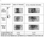
- FIG. 7 is a table showing a result of comparison between a natural mode (whirlwind) in cooling operation of a ceiling type air conditioner according to an embodiment of the present invention and a general auto swing mode
- FIG. 8 is a table showing a result of comparison between a natural mode (whirlwind) in heating operation of a ceiling type air conditioner according to an embodiment of the present invention and a general auto swing mode.
- the airflow distributions of the general auto swing mode and the natural wind mode in the cooling operation of the air conditioner 10 according to the embodiment of the present invention may be confirmed.
- the experimental condition when the outdoor temperature is 35°C, an initial indoor temperature is 33°C, and the fan rotation speed is 600 (RPM), the set temperature of the air conditioner is set to 26°C.
- the vertical temperature distribution in the natural wind mode according to the embodiment of the present invention is more uniform than the vertical temperature distribution in the general auto swing mode.
- the natural wind mode it is possible to solve a problem that it takes a considerable time for the indoor air conditioning environment to reach an environment set by a user in the natural wind mode of the conventional air conditioner.
- the air conditioner 10 according to the embodiment of the present invention can relatively shorten a time required for the indoor temperature to reach a temperature set by a user, it is possible to rapidly provide a pleasant feeling to the user.
- whirlwind is formed and relatively centralized heating (airflow temperature distribution) is provided as compared to the auto swing mode.
- the vertical temperature difference (1.1m to 0.1m) in the natural wind mode is less than the vertical temperature difference in the auto swing mode, by formation of whirlwind.
- the vertical temperature difference value is 2.3(°C) in the auto swing mode and is 1(°C) in the natural wind mode. Therefore, it is possible to prevent a local unpleasant feeling of the user due to a draft phenomenon.
Landscapes
- Engineering & Computer Science (AREA)
- Chemical & Material Sciences (AREA)
- Combustion & Propulsion (AREA)
- Mechanical Engineering (AREA)
- General Engineering & Computer Science (AREA)
- Air Conditioning Control Device (AREA)
- Air-Flow Control Members (AREA)
Applications Claiming Priority (1)
| Application Number | Priority Date | Filing Date | Title |
|---|---|---|---|
| KR1020180063543A KR102167891B1 (ko) | 2018-06-01 | 2018-06-01 | 천장형 공기조화기 및 그 제어방법 |
Publications (2)
| Publication Number | Publication Date |
|---|---|
| EP3575697A1 true EP3575697A1 (de) | 2019-12-04 |
| EP3575697B1 EP3575697B1 (de) | 2023-07-26 |
Family
ID=66685410
Family Applications (1)
| Application Number | Title | Priority Date | Filing Date |
|---|---|---|---|
| EP19177603.8A Active EP3575697B1 (de) | 2018-06-01 | 2019-05-31 | Deckenklimaanlage und steuerungsverfahren dafür |
Country Status (3)
| Country | Link |
|---|---|
| US (1) | US11280516B2 (de) |
| EP (1) | EP3575697B1 (de) |
| KR (1) | KR102167891B1 (de) |
Cited By (5)
| Publication number | Priority date | Publication date | Assignee | Title |
|---|---|---|---|---|
| CN111720991A (zh) * | 2020-04-30 | 2020-09-29 | 广东美的制冷设备有限公司 | 蜗壳组件及风管机 |
| CN111780241A (zh) * | 2020-06-08 | 2020-10-16 | 海信(山东)空调有限公司 | 一种双出风口的空调器 |
| CN113566287A (zh) * | 2021-07-30 | 2021-10-29 | 美的集团武汉暖通设备有限公司 | 天花机及其控制方法、控制装置、计算机可读存储介质 |
| EP4001779A1 (de) * | 2020-11-13 | 2022-05-25 | LG Electronics Inc. | Klimaanlage |
| CN115419992A (zh) * | 2022-09-14 | 2022-12-02 | 珠海格力电器股份有限公司 | 空调器控制方法、装置、电子设备及可读介质 |
Families Citing this family (2)
| Publication number | Priority date | Publication date | Assignee | Title |
|---|---|---|---|---|
| KR20230015146A (ko) * | 2021-07-22 | 2023-01-31 | 엘지전자 주식회사 | 공기조화기 및 그 동작방법 |
| KR20230015147A (ko) * | 2021-07-22 | 2023-01-31 | 엘지전자 주식회사 | 공기조화기 및 그의 제어방법 |
Citations (6)
| Publication number | Priority date | Publication date | Assignee | Title |
|---|---|---|---|---|
| KR20060002528A (ko) | 2004-07-02 | 2006-01-09 | 엘지전자 주식회사 | 공기조화기용 실내기의 토출기류 제어방법 |
| WO2011099608A1 (ja) * | 2010-02-15 | 2011-08-18 | ダイキン工業株式会社 | 空気調和装置の室内ユニット |
| JP2015068603A (ja) * | 2013-09-30 | 2015-04-13 | ダイキン工業株式会社 | 空気調和装置 |
| EP3096088A1 (de) * | 2015-05-20 | 2016-11-23 | Panasonic Intellectual Property Management Co., Ltd. | Raumklimaanlagensystem |
| JP2017215086A (ja) * | 2016-05-31 | 2017-12-07 | 三菱重工サーマルシステムズ株式会社 | 空気調和機 |
| US20180038613A1 (en) * | 2015-02-18 | 2018-02-08 | Samsung Electronics Co., Ltd. | Air conditioner |
Family Cites Families (10)
| Publication number | Priority date | Publication date | Assignee | Title |
|---|---|---|---|---|
| AU2010299201B2 (en) * | 2009-09-28 | 2013-07-25 | Daikin Industries, Ltd. | Control device |
| JP4803297B2 (ja) * | 2009-10-30 | 2011-10-26 | ダイキン工業株式会社 | コントローラ及び空気調和機 |
| JP4952775B2 (ja) * | 2009-11-05 | 2012-06-13 | ダイキン工業株式会社 | 空気調和装置の室内機 |
| AU2011211125B2 (en) * | 2010-01-26 | 2013-09-19 | Daikin Industries, Ltd. | Ceiling-mounted indoor unit for air conditioning apparatus |
| JP5403125B2 (ja) * | 2011-10-31 | 2014-01-29 | ダイキン工業株式会社 | 空調室内機 |
| JP5536158B2 (ja) * | 2011-12-28 | 2014-07-02 | ダイキン工業株式会社 | 空調室内機 |
| KR101662377B1 (ko) * | 2014-01-27 | 2016-10-04 | 엘지전자 주식회사 | 공기조화기의 실내기 |
| KR102393966B1 (ko) * | 2015-02-18 | 2022-05-04 | 삼성전자주식회사 | 공기조화기 |
| JP6222211B2 (ja) * | 2015-12-18 | 2017-11-01 | ダイキン工業株式会社 | 空気調和装置 |
| KR102531649B1 (ko) * | 2018-01-17 | 2023-05-11 | 삼성전자주식회사 | 공기조화기 |
-
2018
- 2018-06-01 KR KR1020180063543A patent/KR102167891B1/ko active Active
-
2019
- 2019-05-31 EP EP19177603.8A patent/EP3575697B1/de active Active
- 2019-05-31 US US16/427,434 patent/US11280516B2/en active Active
Patent Citations (6)
| Publication number | Priority date | Publication date | Assignee | Title |
|---|---|---|---|---|
| KR20060002528A (ko) | 2004-07-02 | 2006-01-09 | 엘지전자 주식회사 | 공기조화기용 실내기의 토출기류 제어방법 |
| WO2011099608A1 (ja) * | 2010-02-15 | 2011-08-18 | ダイキン工業株式会社 | 空気調和装置の室内ユニット |
| JP2015068603A (ja) * | 2013-09-30 | 2015-04-13 | ダイキン工業株式会社 | 空気調和装置 |
| US20180038613A1 (en) * | 2015-02-18 | 2018-02-08 | Samsung Electronics Co., Ltd. | Air conditioner |
| EP3096088A1 (de) * | 2015-05-20 | 2016-11-23 | Panasonic Intellectual Property Management Co., Ltd. | Raumklimaanlagensystem |
| JP2017215086A (ja) * | 2016-05-31 | 2017-12-07 | 三菱重工サーマルシステムズ株式会社 | 空気調和機 |
Cited By (5)
| Publication number | Priority date | Publication date | Assignee | Title |
|---|---|---|---|---|
| CN111720991A (zh) * | 2020-04-30 | 2020-09-29 | 广东美的制冷设备有限公司 | 蜗壳组件及风管机 |
| CN111780241A (zh) * | 2020-06-08 | 2020-10-16 | 海信(山东)空调有限公司 | 一种双出风口的空调器 |
| EP4001779A1 (de) * | 2020-11-13 | 2022-05-25 | LG Electronics Inc. | Klimaanlage |
| CN113566287A (zh) * | 2021-07-30 | 2021-10-29 | 美的集团武汉暖通设备有限公司 | 天花机及其控制方法、控制装置、计算机可读存储介质 |
| CN115419992A (zh) * | 2022-09-14 | 2022-12-02 | 珠海格力电器股份有限公司 | 空调器控制方法、装置、电子设备及可读介质 |
Also Published As
| Publication number | Publication date |
|---|---|
| EP3575697B1 (de) | 2023-07-26 |
| US20190368773A1 (en) | 2019-12-05 |
| KR20190137408A (ko) | 2019-12-11 |
| KR102167891B1 (ko) | 2020-10-20 |
| US11280516B2 (en) | 2022-03-22 |
Similar Documents
| Publication | Publication Date | Title |
|---|---|---|
| EP3575697B1 (de) | Deckenklimaanlage und steuerungsverfahren dafür | |
| US12339025B2 (en) | Method for controlling a ceiling type air conditioner | |
| EP2719959B1 (de) | Klimaanlage | |
| EP3569940B1 (de) | Steuerungsverfahren einer deckenklimaanlage | |
| KR100809784B1 (ko) | 횡류팬을 포함하는 공기 조화기 | |
| KR101554722B1 (ko) | 풍량 가변장치를 구비하는 공기조화기 | |
| US20150007967A1 (en) | Wind-visor and air conditioner having the same | |
| JP5408317B1 (ja) | 空調室内機 | |
| AU2006202532A1 (en) | Air conditioner and control method of the same | |
| KR102476796B1 (ko) | 공기조화기의 실내기 | |
| KR101476437B1 (ko) | 공조장치, 공조장치의 베인제어장치, 및 공조장치의베인제어방법 | |
| KR101901303B1 (ko) | 공기조화기 | |
| KR102343464B1 (ko) | 천장형 에어컨 실내기 | |
| EP3885667B1 (de) | Innenraumeinheit einer klimaanlage | |
| CN212390516U (zh) | 空调器 | |
| KR20190051676A (ko) | 공기조화기의 실내기 | |
| KR102457778B1 (ko) | 공기조화기 | |
| CN114110807B (zh) | 空调器和空调器的控制方法 | |
| KR100484928B1 (ko) | 공기 조화기 및 그 제어방법 | |
| KR102822767B1 (ko) | 모듈공조기, 및 공조시스템 | |
| JPH0979646A (ja) | 空気調和装置 | |
| KR20250046465A (ko) | 공기조화기 | |
| KR20080063554A (ko) | 공기조화기 | |
| CN111140928A (zh) | 一种飓风发生器、空调室内机及空调器 | |
| JP2004286287A (ja) | 空気調和機 |
Legal Events
| Date | Code | Title | Description |
|---|---|---|---|
| PUAI | Public reference made under article 153(3) epc to a published international application that has entered the european phase |
Free format text: ORIGINAL CODE: 0009012 |
|
| STAA | Information on the status of an ep patent application or granted ep patent |
Free format text: STATUS: REQUEST FOR EXAMINATION WAS MADE |
|
| 17P | Request for examination filed |
Effective date: 20190531 |
|
| AK | Designated contracting states |
Kind code of ref document: A1 Designated state(s): AL AT BE BG CH CY CZ DE DK EE ES FI FR GB GR HR HU IE IS IT LI LT LU LV MC MK MT NL NO PL PT RO RS SE SI SK SM TR |
|
| AX | Request for extension of the european patent |
Extension state: BA ME |
|
| RBV | Designated contracting states (corrected) |
Designated state(s): AL AT BE BG CH CY CZ DE DK EE ES FI FR GB GR HR HU IE IS IT LI LT LU LV MC MK MT NL NO PL PT RO RS SE SI SK SM TR |
|
| STAA | Information on the status of an ep patent application or granted ep patent |
Free format text: STATUS: EXAMINATION IS IN PROGRESS |
|
| 17Q | First examination report despatched |
Effective date: 20210526 |
|
| GRAP | Despatch of communication of intention to grant a patent |
Free format text: ORIGINAL CODE: EPIDOSNIGR1 |
|
| STAA | Information on the status of an ep patent application or granted ep patent |
Free format text: STATUS: GRANT OF PATENT IS INTENDED |
|
| INTG | Intention to grant announced |
Effective date: 20230220 |
|
| GRAS | Grant fee paid |
Free format text: ORIGINAL CODE: EPIDOSNIGR3 |
|
| GRAA | (expected) grant |
Free format text: ORIGINAL CODE: 0009210 |
|
| STAA | Information on the status of an ep patent application or granted ep patent |
Free format text: STATUS: THE PATENT HAS BEEN GRANTED |
|
| AK | Designated contracting states |
Kind code of ref document: B1 Designated state(s): AL AT BE BG CH CY CZ DE DK EE ES FI FR GB GR HR HU IE IS IT LI LT LU LV MC MK MT NL NO PL PT RO RS SE SI SK SM TR |
|
| REG | Reference to a national code |
Ref country code: CH Ref legal event code: EP |
|
| REG | Reference to a national code |
Ref country code: DE Ref legal event code: R096 Ref document number: 602019033385 Country of ref document: DE |
|
| REG | Reference to a national code |
Ref country code: IE Ref legal event code: FG4D |
|
| REG | Reference to a national code |
Ref country code: LT Ref legal event code: MG9D |
|
| REG | Reference to a national code |
Ref country code: NL Ref legal event code: MP Effective date: 20230726 |
|
| REG | Reference to a national code |
Ref country code: AT Ref legal event code: MK05 Ref document number: 1592316 Country of ref document: AT Kind code of ref document: T Effective date: 20230726 |
|
| PG25 | Lapsed in a contracting state [announced via postgrant information from national office to epo] |
Ref country code: NL Free format text: LAPSE BECAUSE OF FAILURE TO SUBMIT A TRANSLATION OF THE DESCRIPTION OR TO PAY THE FEE WITHIN THE PRESCRIBED TIME-LIMIT Effective date: 20230726 |
|
| PG25 | Lapsed in a contracting state [announced via postgrant information from national office to epo] |
Ref country code: GR Free format text: LAPSE BECAUSE OF FAILURE TO SUBMIT A TRANSLATION OF THE DESCRIPTION OR TO PAY THE FEE WITHIN THE PRESCRIBED TIME-LIMIT Effective date: 20231027 |
|
| PG25 | Lapsed in a contracting state [announced via postgrant information from national office to epo] |
Ref country code: IS Free format text: LAPSE BECAUSE OF FAILURE TO SUBMIT A TRANSLATION OF THE DESCRIPTION OR TO PAY THE FEE WITHIN THE PRESCRIBED TIME-LIMIT Effective date: 20231126 |
|
| PG25 | Lapsed in a contracting state [announced via postgrant information from national office to epo] |
Ref country code: SE Free format text: LAPSE BECAUSE OF FAILURE TO SUBMIT A TRANSLATION OF THE DESCRIPTION OR TO PAY THE FEE WITHIN THE PRESCRIBED TIME-LIMIT Effective date: 20230726 Ref country code: RS Free format text: LAPSE BECAUSE OF FAILURE TO SUBMIT A TRANSLATION OF THE DESCRIPTION OR TO PAY THE FEE WITHIN THE PRESCRIBED TIME-LIMIT Effective date: 20230726 Ref country code: PT Free format text: LAPSE BECAUSE OF FAILURE TO SUBMIT A TRANSLATION OF THE DESCRIPTION OR TO PAY THE FEE WITHIN THE PRESCRIBED TIME-LIMIT Effective date: 20231127 Ref country code: NO Free format text: LAPSE BECAUSE OF FAILURE TO SUBMIT A TRANSLATION OF THE DESCRIPTION OR TO PAY THE FEE WITHIN THE PRESCRIBED TIME-LIMIT Effective date: 20231026 Ref country code: LV Free format text: LAPSE BECAUSE OF FAILURE TO SUBMIT A TRANSLATION OF THE DESCRIPTION OR TO PAY THE FEE WITHIN THE PRESCRIBED TIME-LIMIT Effective date: 20230726 Ref country code: LT Free format text: LAPSE BECAUSE OF FAILURE TO SUBMIT A TRANSLATION OF THE DESCRIPTION OR TO PAY THE FEE WITHIN THE PRESCRIBED TIME-LIMIT Effective date: 20230726 Ref country code: IS Free format text: LAPSE BECAUSE OF FAILURE TO SUBMIT A TRANSLATION OF THE DESCRIPTION OR TO PAY THE FEE WITHIN THE PRESCRIBED TIME-LIMIT Effective date: 20231126 Ref country code: HR Free format text: LAPSE BECAUSE OF FAILURE TO SUBMIT A TRANSLATION OF THE DESCRIPTION OR TO PAY THE FEE WITHIN THE PRESCRIBED TIME-LIMIT Effective date: 20230726 Ref country code: GR Free format text: LAPSE BECAUSE OF FAILURE TO SUBMIT A TRANSLATION OF THE DESCRIPTION OR TO PAY THE FEE WITHIN THE PRESCRIBED TIME-LIMIT Effective date: 20231027 Ref country code: FI Free format text: LAPSE BECAUSE OF FAILURE TO SUBMIT A TRANSLATION OF THE DESCRIPTION OR TO PAY THE FEE WITHIN THE PRESCRIBED TIME-LIMIT Effective date: 20230726 Ref country code: AT Free format text: LAPSE BECAUSE OF FAILURE TO SUBMIT A TRANSLATION OF THE DESCRIPTION OR TO PAY THE FEE WITHIN THE PRESCRIBED TIME-LIMIT Effective date: 20230726 |
|
| PG25 | Lapsed in a contracting state [announced via postgrant information from national office to epo] |
Ref country code: PL Free format text: LAPSE BECAUSE OF FAILURE TO SUBMIT A TRANSLATION OF THE DESCRIPTION OR TO PAY THE FEE WITHIN THE PRESCRIBED TIME-LIMIT Effective date: 20230726 |
|
| PG25 | Lapsed in a contracting state [announced via postgrant information from national office to epo] |
Ref country code: ES Free format text: LAPSE BECAUSE OF FAILURE TO SUBMIT A TRANSLATION OF THE DESCRIPTION OR TO PAY THE FEE WITHIN THE PRESCRIBED TIME-LIMIT Effective date: 20230726 |
|
| REG | Reference to a national code |
Ref country code: DE Ref legal event code: R097 Ref document number: 602019033385 Country of ref document: DE |
|
| PG25 | Lapsed in a contracting state [announced via postgrant information from national office to epo] |
Ref country code: SM Free format text: LAPSE BECAUSE OF FAILURE TO SUBMIT A TRANSLATION OF THE DESCRIPTION OR TO PAY THE FEE WITHIN THE PRESCRIBED TIME-LIMIT Effective date: 20230726 Ref country code: RO Free format text: LAPSE BECAUSE OF FAILURE TO SUBMIT A TRANSLATION OF THE DESCRIPTION OR TO PAY THE FEE WITHIN THE PRESCRIBED TIME-LIMIT Effective date: 20230726 Ref country code: ES Free format text: LAPSE BECAUSE OF FAILURE TO SUBMIT A TRANSLATION OF THE DESCRIPTION OR TO PAY THE FEE WITHIN THE PRESCRIBED TIME-LIMIT Effective date: 20230726 Ref country code: EE Free format text: LAPSE BECAUSE OF FAILURE TO SUBMIT A TRANSLATION OF THE DESCRIPTION OR TO PAY THE FEE WITHIN THE PRESCRIBED TIME-LIMIT Effective date: 20230726 Ref country code: DK Free format text: LAPSE BECAUSE OF FAILURE TO SUBMIT A TRANSLATION OF THE DESCRIPTION OR TO PAY THE FEE WITHIN THE PRESCRIBED TIME-LIMIT Effective date: 20230726 Ref country code: CZ Free format text: LAPSE BECAUSE OF FAILURE TO SUBMIT A TRANSLATION OF THE DESCRIPTION OR TO PAY THE FEE WITHIN THE PRESCRIBED TIME-LIMIT Effective date: 20230726 Ref country code: SK Free format text: LAPSE BECAUSE OF FAILURE TO SUBMIT A TRANSLATION OF THE DESCRIPTION OR TO PAY THE FEE WITHIN THE PRESCRIBED TIME-LIMIT Effective date: 20230726 |
|
| PG25 | Lapsed in a contracting state [announced via postgrant information from national office to epo] |
Ref country code: IT Free format text: LAPSE BECAUSE OF FAILURE TO SUBMIT A TRANSLATION OF THE DESCRIPTION OR TO PAY THE FEE WITHIN THE PRESCRIBED TIME-LIMIT Effective date: 20230726 |
|
| PLBE | No opposition filed within time limit |
Free format text: ORIGINAL CODE: 0009261 |
|
| STAA | Information on the status of an ep patent application or granted ep patent |
Free format text: STATUS: NO OPPOSITION FILED WITHIN TIME LIMIT |
|
| 26N | No opposition filed |
Effective date: 20240429 |
|
| PG25 | Lapsed in a contracting state [announced via postgrant information from national office to epo] |
Ref country code: SI Free format text: LAPSE BECAUSE OF FAILURE TO SUBMIT A TRANSLATION OF THE DESCRIPTION OR TO PAY THE FEE WITHIN THE PRESCRIBED TIME-LIMIT Effective date: 20230726 |
|
| PG25 | Lapsed in a contracting state [announced via postgrant information from national office to epo] |
Ref country code: BG Free format text: LAPSE BECAUSE OF FAILURE TO SUBMIT A TRANSLATION OF THE DESCRIPTION OR TO PAY THE FEE WITHIN THE PRESCRIBED TIME-LIMIT Effective date: 20230726 |
|
| PG25 | Lapsed in a contracting state [announced via postgrant information from national office to epo] |
Ref country code: BG Free format text: LAPSE BECAUSE OF FAILURE TO SUBMIT A TRANSLATION OF THE DESCRIPTION OR TO PAY THE FEE WITHIN THE PRESCRIBED TIME-LIMIT Effective date: 20230726 |
|
| REG | Reference to a national code |
Ref country code: CH Ref legal event code: PL |
|
| PG25 | Lapsed in a contracting state [announced via postgrant information from national office to epo] |
Ref country code: MC Free format text: LAPSE BECAUSE OF FAILURE TO SUBMIT A TRANSLATION OF THE DESCRIPTION OR TO PAY THE FEE WITHIN THE PRESCRIBED TIME-LIMIT Effective date: 20230726 |
|
| PG25 | Lapsed in a contracting state [announced via postgrant information from national office to epo] |
Ref country code: LU Free format text: LAPSE BECAUSE OF NON-PAYMENT OF DUE FEES Effective date: 20240531 |
|
| GBPC | Gb: european patent ceased through non-payment of renewal fee |
Effective date: 20240531 |
|
| PG25 | Lapsed in a contracting state [announced via postgrant information from national office to epo] |
Ref country code: MC Free format text: LAPSE BECAUSE OF FAILURE TO SUBMIT A TRANSLATION OF THE DESCRIPTION OR TO PAY THE FEE WITHIN THE PRESCRIBED TIME-LIMIT Effective date: 20230726 Ref country code: LU Free format text: LAPSE BECAUSE OF NON-PAYMENT OF DUE FEES Effective date: 20240531 Ref country code: CH Free format text: LAPSE BECAUSE OF NON-PAYMENT OF DUE FEES Effective date: 20240531 |
|
| REG | Reference to a national code |
Ref country code: BE Ref legal event code: MM Effective date: 20240531 |
|
| PG25 | Lapsed in a contracting state [announced via postgrant information from national office to epo] |
Ref country code: IE Free format text: LAPSE BECAUSE OF NON-PAYMENT OF DUE FEES Effective date: 20240531 |
|
| PG25 | Lapsed in a contracting state [announced via postgrant information from national office to epo] |
Ref country code: BE Free format text: LAPSE BECAUSE OF NON-PAYMENT OF DUE FEES Effective date: 20240531 |
|
| PG25 | Lapsed in a contracting state [announced via postgrant information from national office to epo] |
Ref country code: FR Free format text: LAPSE BECAUSE OF NON-PAYMENT OF DUE FEES Effective date: 20240531 |
|
| PG25 | Lapsed in a contracting state [announced via postgrant information from national office to epo] |
Ref country code: GB Free format text: LAPSE BECAUSE OF NON-PAYMENT OF DUE FEES Effective date: 20240531 |
|
| PGFP | Annual fee paid to national office [announced via postgrant information from national office to epo] |
Ref country code: DE Payment date: 20250407 Year of fee payment: 7 |
|
| PG25 | Lapsed in a contracting state [announced via postgrant information from national office to epo] |
Ref country code: CY Free format text: LAPSE BECAUSE OF FAILURE TO SUBMIT A TRANSLATION OF THE DESCRIPTION OR TO PAY THE FEE WITHIN THE PRESCRIBED TIME-LIMIT; INVALID AB INITIO Effective date: 20190531 |
|
| PG25 | Lapsed in a contracting state [announced via postgrant information from national office to epo] |
Ref country code: HU Free format text: LAPSE BECAUSE OF FAILURE TO SUBMIT A TRANSLATION OF THE DESCRIPTION OR TO PAY THE FEE WITHIN THE PRESCRIBED TIME-LIMIT; INVALID AB INITIO Effective date: 20190531 |