EP3576431A1 - Procédé de fonctionnement d'une unité de haut-parleur ainsi qu'unité de haut-parleur - Google Patents
Procédé de fonctionnement d'une unité de haut-parleur ainsi qu'unité de haut-parleur Download PDFInfo
- Publication number
- EP3576431A1 EP3576431A1 EP19176818.3A EP19176818A EP3576431A1 EP 3576431 A1 EP3576431 A1 EP 3576431A1 EP 19176818 A EP19176818 A EP 19176818A EP 3576431 A1 EP3576431 A1 EP 3576431A1
- Authority
- EP
- European Patent Office
- Prior art keywords
- interval
- loudspeaker
- sound
- mems
- microphone
- Prior art date
- Legal status (The legal status is an assumption and is not a legal conclusion. Google has not performed a legal analysis and makes no representation as to the accuracy of the status listed.)
- Withdrawn
Links
Images


Classifications
-
- H—ELECTRICITY
- H04—ELECTRIC COMMUNICATION TECHNIQUE
- H04R—LOUDSPEAKERS, MICROPHONES, GRAMOPHONE PICK-UPS OR LIKE ACOUSTIC ELECTROMECHANICAL TRANSDUCERS; ELECTRIC HEARING AIDS; PUBLIC ADDRESS SYSTEMS
- H04R19/00—Electrostatic transducers
- H04R19/005—Electrostatic transducers using semiconductor materials
-
- G—PHYSICS
- G01—MEASURING; TESTING
- G01S—RADIO DIRECTION-FINDING; RADIO NAVIGATION; DETERMINING DISTANCE OR VELOCITY BY USE OF RADIO WAVES; LOCATING OR PRESENCE-DETECTING BY USE OF THE REFLECTION OR RERADIATION OF RADIO WAVES; ANALOGOUS ARRANGEMENTS USING OTHER WAVES
- G01S15/00—Systems using the reflection or reradiation of acoustic waves, e.g. sonar systems
- G01S15/02—Systems using the reflection or reradiation of acoustic waves, e.g. sonar systems using reflection of acoustic waves
- G01S15/06—Systems determining the position data of a target
- G01S15/08—Systems for measuring distance only
-
- H—ELECTRICITY
- H04—ELECTRIC COMMUNICATION TECHNIQUE
- H04R—LOUDSPEAKERS, MICROPHONES, GRAMOPHONE PICK-UPS OR LIKE ACOUSTIC ELECTROMECHANICAL TRANSDUCERS; ELECTRIC HEARING AIDS; PUBLIC ADDRESS SYSTEMS
- H04R29/00—Monitoring arrangements; Testing arrangements
- H04R29/001—Monitoring arrangements; Testing arrangements for loudspeakers
-
- G—PHYSICS
- G01—MEASURING; TESTING
- G01S—RADIO DIRECTION-FINDING; RADIO NAVIGATION; DETERMINING DISTANCE OR VELOCITY BY USE OF RADIO WAVES; LOCATING OR PRESENCE-DETECTING BY USE OF THE REFLECTION OR RERADIATION OF RADIO WAVES; ANALOGOUS ARRANGEMENTS USING OTHER WAVES
- G01S15/00—Systems using the reflection or reradiation of acoustic waves, e.g. sonar systems
- G01S15/88—Sonar systems specially adapted for specific applications
- G01S15/89—Sonar systems specially adapted for specific applications for mapping or imaging
-
- G—PHYSICS
- G06—COMPUTING OR CALCULATING; COUNTING
- G06F—ELECTRIC DIGITAL DATA PROCESSING
- G06F1/00—Details not covered by groups G06F3/00 - G06F13/00 and G06F21/00
- G06F1/16—Constructional details or arrangements
- G06F1/1613—Constructional details or arrangements for portable computers
- G06F1/1626—Constructional details or arrangements for portable computers with a single-body enclosure integrating a flat display, e.g. Personal Digital Assistants [PDAs]
-
- G—PHYSICS
- G06—COMPUTING OR CALCULATING; COUNTING
- G06F—ELECTRIC DIGITAL DATA PROCESSING
- G06F1/00—Details not covered by groups G06F3/00 - G06F13/00 and G06F21/00
- G06F1/16—Constructional details or arrangements
- G06F1/1613—Constructional details or arrangements for portable computers
- G06F1/1633—Constructional details or arrangements of portable computers not specific to the type of enclosures covered by groups G06F1/1615 - G06F1/1626
- G06F1/1684—Constructional details or arrangements related to integrated I/O peripherals not covered by groups G06F1/1635 - G06F1/1675
- G06F1/1688—Constructional details or arrangements related to integrated I/O peripherals not covered by groups G06F1/1635 - G06F1/1675 the I/O peripheral being integrated loudspeakers
-
- G—PHYSICS
- G06—COMPUTING OR CALCULATING; COUNTING
- G06F—ELECTRIC DIGITAL DATA PROCESSING
- G06F3/00—Input arrangements for transferring data to be processed into a form capable of being handled by the computer; Output arrangements for transferring data from processing unit to output unit, e.g. interface arrangements
- G06F3/16—Sound input; Sound output
- G06F3/165—Management of the audio stream, e.g. setting of volume, audio stream path
-
- H—ELECTRICITY
- H04—ELECTRIC COMMUNICATION TECHNIQUE
- H04M—TELEPHONIC COMMUNICATION
- H04M1/00—Substation equipment, e.g. for use by subscribers
- H04M1/02—Constructional features of telephone sets
- H04M1/03—Constructional features of telephone transmitters or receivers, e.g. telephone hand-sets
-
- H—ELECTRICITY
- H04—ELECTRIC COMMUNICATION TECHNIQUE
- H04R—LOUDSPEAKERS, MICROPHONES, GRAMOPHONE PICK-UPS OR LIKE ACOUSTIC ELECTROMECHANICAL TRANSDUCERS; ELECTRIC HEARING AIDS; PUBLIC ADDRESS SYSTEMS
- H04R17/00—Piezoelectric transducers; Electrostrictive transducers
-
- H—ELECTRICITY
- H04—ELECTRIC COMMUNICATION TECHNIQUE
- H04R—LOUDSPEAKERS, MICROPHONES, GRAMOPHONE PICK-UPS OR LIKE ACOUSTIC ELECTROMECHANICAL TRANSDUCERS; ELECTRIC HEARING AIDS; PUBLIC ADDRESS SYSTEMS
- H04R19/00—Electrostatic transducers
- H04R19/02—Loudspeakers
-
- H—ELECTRICITY
- H04—ELECTRIC COMMUNICATION TECHNIQUE
- H04R—LOUDSPEAKERS, MICROPHONES, GRAMOPHONE PICK-UPS OR LIKE ACOUSTIC ELECTROMECHANICAL TRANSDUCERS; ELECTRIC HEARING AIDS; PUBLIC ADDRESS SYSTEMS
- H04R19/00—Electrostatic transducers
- H04R19/04—Microphones
-
- H—ELECTRICITY
- H04—ELECTRIC COMMUNICATION TECHNIQUE
- H04R—LOUDSPEAKERS, MICROPHONES, GRAMOPHONE PICK-UPS OR LIKE ACOUSTIC ELECTROMECHANICAL TRANSDUCERS; ELECTRIC HEARING AIDS; PUBLIC ADDRESS SYSTEMS
- H04R29/00—Monitoring arrangements; Testing arrangements
- H04R29/004—Monitoring arrangements; Testing arrangements for microphones
-
- H—ELECTRICITY
- H04—ELECTRIC COMMUNICATION TECHNIQUE
- H04R—LOUDSPEAKERS, MICROPHONES, GRAMOPHONE PICK-UPS OR LIKE ACOUSTIC ELECTROMECHANICAL TRANSDUCERS; ELECTRIC HEARING AIDS; PUBLIC ADDRESS SYSTEMS
- H04R3/00—Circuits for transducers
- H04R3/04—Circuits for transducers for correcting frequency response
-
- H—ELECTRICITY
- H04—ELECTRIC COMMUNICATION TECHNIQUE
- H04R—LOUDSPEAKERS, MICROPHONES, GRAMOPHONE PICK-UPS OR LIKE ACOUSTIC ELECTROMECHANICAL TRANSDUCERS; ELECTRIC HEARING AIDS; PUBLIC ADDRESS SYSTEMS
- H04R3/00—Circuits for transducers
- H04R3/12—Circuits for transducers for distributing signals to two or more loudspeakers
-
- B—PERFORMING OPERATIONS; TRANSPORTING
- B06—GENERATING OR TRANSMITTING MECHANICAL VIBRATIONS IN GENERAL
- B06B—METHODS OR APPARATUS FOR GENERATING OR TRANSMITTING MECHANICAL VIBRATIONS OF INFRASONIC, SONIC, OR ULTRASONIC FREQUENCY, e.g. FOR PERFORMING MECHANICAL WORK IN GENERAL
- B06B1/00—Methods or apparatus for generating mechanical vibrations of infrasonic, sonic, or ultrasonic frequency
- B06B1/02—Methods or apparatus for generating mechanical vibrations of infrasonic, sonic, or ultrasonic frequency making use of electrical energy
- B06B1/0292—Electrostatic transducers, e.g. electret-type
-
- B—PERFORMING OPERATIONS; TRANSPORTING
- B06—GENERATING OR TRANSMITTING MECHANICAL VIBRATIONS IN GENERAL
- B06B—METHODS OR APPARATUS FOR GENERATING OR TRANSMITTING MECHANICAL VIBRATIONS OF INFRASONIC, SONIC, OR ULTRASONIC FREQUENCY, e.g. FOR PERFORMING MECHANICAL WORK IN GENERAL
- B06B1/00—Methods or apparatus for generating mechanical vibrations of infrasonic, sonic, or ultrasonic frequency
- B06B1/02—Methods or apparatus for generating mechanical vibrations of infrasonic, sonic, or ultrasonic frequency making use of electrical energy
- B06B1/06—Methods or apparatus for generating mechanical vibrations of infrasonic, sonic, or ultrasonic frequency making use of electrical energy operating with piezoelectric effect or with electrostriction
-
- G—PHYSICS
- G06—COMPUTING OR CALCULATING; COUNTING
- G06F—ELECTRIC DIGITAL DATA PROCESSING
- G06F3/00—Input arrangements for transferring data to be processed into a form capable of being handled by the computer; Output arrangements for transferring data from processing unit to output unit, e.g. interface arrangements
- G06F3/01—Input arrangements or combined input and output arrangements for interaction between user and computer
- G06F3/017—Gesture based interaction, e.g. based on a set of recognized hand gestures
-
- G—PHYSICS
- G10—MUSICAL INSTRUMENTS; ACOUSTICS
- G10K—SOUND-PRODUCING DEVICES; METHODS OR DEVICES FOR PROTECTING AGAINST, OR FOR DAMPING, NOISE OR OTHER ACOUSTIC WAVES IN GENERAL; ACOUSTICS NOT OTHERWISE PROVIDED FOR
- G10K9/00—Devices in which sound is produced by vibrating a diaphragm or analogous element, e.g. fog horns, vehicle hooters or buzzers
- G10K9/12—Devices in which sound is produced by vibrating a diaphragm or analogous element, e.g. fog horns, vehicle hooters or buzzers electrically operated
-
- H—ELECTRICITY
- H04—ELECTRIC COMMUNICATION TECHNIQUE
- H04M—TELEPHONIC COMMUNICATION
- H04M1/00—Substation equipment, e.g. for use by subscribers
- H04M1/72—Mobile telephones; Cordless telephones, i.e. devices for establishing wireless links to base stations without route selection
- H04M1/724—User interfaces specially adapted for cordless or mobile telephones
- H04M1/72448—User interfaces specially adapted for cordless or mobile telephones with means for adapting the functionality of the device according to specific conditions
- H04M1/72454—User interfaces specially adapted for cordless or mobile telephones with means for adapting the functionality of the device according to specific conditions according to context-related or environment-related conditions
-
- H—ELECTRICITY
- H04—ELECTRIC COMMUNICATION TECHNIQUE
- H04R—LOUDSPEAKERS, MICROPHONES, GRAMOPHONE PICK-UPS OR LIKE ACOUSTIC ELECTROMECHANICAL TRANSDUCERS; ELECTRIC HEARING AIDS; PUBLIC ADDRESS SYSTEMS
- H04R1/00—Details of transducers, loudspeakers or microphones
- H04R1/20—Arrangements for obtaining desired frequency or directional characteristics
- H04R1/22—Arrangements for obtaining desired frequency or directional characteristics for obtaining desired frequency characteristic only
- H04R1/225—Arrangements for obtaining desired frequency or directional characteristics for obtaining desired frequency characteristic only for telephonic receivers
-
- H—ELECTRICITY
- H04—ELECTRIC COMMUNICATION TECHNIQUE
- H04R—LOUDSPEAKERS, MICROPHONES, GRAMOPHONE PICK-UPS OR LIKE ACOUSTIC ELECTROMECHANICAL TRANSDUCERS; ELECTRIC HEARING AIDS; PUBLIC ADDRESS SYSTEMS
- H04R2201/00—Details of transducers, loudspeakers or microphones covered by H04R1/00 but not provided for in any of its subgroups
- H04R2201/003—Mems transducers or their use
-
- H—ELECTRICITY
- H04—ELECTRIC COMMUNICATION TECHNIQUE
- H04R—LOUDSPEAKERS, MICROPHONES, GRAMOPHONE PICK-UPS OR LIKE ACOUSTIC ELECTROMECHANICAL TRANSDUCERS; ELECTRIC HEARING AIDS; PUBLIC ADDRESS SYSTEMS
- H04R2201/00—Details of transducers, loudspeakers or microphones covered by H04R1/00 but not provided for in any of its subgroups
- H04R2201/02—Details casings, cabinets or mounting therein for transducers covered by H04R1/02 but not provided for in any of its subgroups
- H04R2201/028—Structural combinations of loudspeakers with built-in power amplifiers, e.g. in the same acoustic enclosure
-
- H—ELECTRICITY
- H04—ELECTRIC COMMUNICATION TECHNIQUE
- H04R—LOUDSPEAKERS, MICROPHONES, GRAMOPHONE PICK-UPS OR LIKE ACOUSTIC ELECTROMECHANICAL TRANSDUCERS; ELECTRIC HEARING AIDS; PUBLIC ADDRESS SYSTEMS
- H04R2400/00—Loudspeakers
- H04R2400/01—Transducers used as a loudspeaker to generate sound aswell as a microphone to detect sound
-
- H—ELECTRICITY
- H04—ELECTRIC COMMUNICATION TECHNIQUE
- H04R—LOUDSPEAKERS, MICROPHONES, GRAMOPHONE PICK-UPS OR LIKE ACOUSTIC ELECTROMECHANICAL TRANSDUCERS; ELECTRIC HEARING AIDS; PUBLIC ADDRESS SYSTEMS
- H04R2400/00—Loudspeakers
- H04R2400/03—Transducers capable of generating both sound as well as tactile vibration, e.g. as used in cellular phones
-
- H—ELECTRICITY
- H04—ELECTRIC COMMUNICATION TECHNIQUE
- H04R—LOUDSPEAKERS, MICROPHONES, GRAMOPHONE PICK-UPS OR LIKE ACOUSTIC ELECTROMECHANICAL TRANSDUCERS; ELECTRIC HEARING AIDS; PUBLIC ADDRESS SYSTEMS
- H04R2430/00—Signal processing covered by H04R, not provided for in its groups
-
- H—ELECTRICITY
- H04—ELECTRIC COMMUNICATION TECHNIQUE
- H04R—LOUDSPEAKERS, MICROPHONES, GRAMOPHONE PICK-UPS OR LIKE ACOUSTIC ELECTROMECHANICAL TRANSDUCERS; ELECTRIC HEARING AIDS; PUBLIC ADDRESS SYSTEMS
- H04R2430/00—Signal processing covered by H04R, not provided for in its groups
- H04R2430/03—Synergistic effects of band splitting and sub-band processing
-
- H—ELECTRICITY
- H04—ELECTRIC COMMUNICATION TECHNIQUE
- H04R—LOUDSPEAKERS, MICROPHONES, GRAMOPHONE PICK-UPS OR LIKE ACOUSTIC ELECTROMECHANICAL TRANSDUCERS; ELECTRIC HEARING AIDS; PUBLIC ADDRESS SYSTEMS
- H04R2499/00—Aspects covered by H04R or H04S not otherwise provided for in their subgroups
- H04R2499/10—General applications
- H04R2499/11—Transducers incorporated or for use in hand-held devices, e.g. mobile phones, PDA's, camera's
-
- H—ELECTRICITY
- H04—ELECTRIC COMMUNICATION TECHNIQUE
- H04R—LOUDSPEAKERS, MICROPHONES, GRAMOPHONE PICK-UPS OR LIKE ACOUSTIC ELECTROMECHANICAL TRANSDUCERS; ELECTRIC HEARING AIDS; PUBLIC ADDRESS SYSTEMS
- H04R3/00—Circuits for transducers
- H04R3/12—Circuits for transducers for distributing signals to two or more loudspeakers
- H04R3/14—Cross-over networks
Definitions
- the present invention relates to a method for operating a loudspeaker unit, in particular for a portable device, in which sound waves in the audible wavelength range are generated and / or detected by means of a MEMS sound transducer of the loudspeaker unit. Moreover, the present invention relates to a speaker unit, in particular for a portable device, with a MEMS sound transducer for generating and / or detecting sound waves in the audible wavelength range.
- a loudspeaker arrangement with a MEMS sound transducer for generating and / or detecting sound waves in the audible wavelength spectrum is known.
- the object of the present invention is therefore to improve the state of the art.
- the object is achieved by a method for operating a loudspeaker unit and a loudspeaker unit having the features of the independent patent claims.
- a method for operating a loudspeaker unit is proposed, wherein the loudspeaker unit can be arranged, for example, in a portable device.
- the portable device may be, for example, a smartphone, a tablet, laptop or the like, with which, for example, music, sounds and / or speech can be generated.
- sound waves in the audible wavelength range are generated by means of a MEMS sound transducer of the loudspeaker unit.
- the audible wavelength range for human hearing begins at about 20 Hz in the lower range and extends to about 20 kHz in the upper range. Sound waves that are lower or have a higher frequency can not be perceived by the human ear.
- the abbreviation MEMS stands for microelectromechanical systems.
- the MEMS transducer can thus be used as a loudspeaker. Additionally or alternatively, in the method by means of the MEMS sound transducer and sound waves in the audible wavelength range can be detected. The MEMS transducer can thus be used as a microphone.
- the MEMS sound transducer is additionally operated as an ultrasonic proximity sensor by a control unit of the loudspeaker unit.
- the MEMS sound transducer can thus be operated to generate and / or detect sound waves in the audible wavelength range and as an ultrasonic proximity sensor.
- the speaker unit can be made space-saving and cost-effective.
- ultrasonic waves are generated and detected with the MEMS transducer for measuring a distance between itself and an object.
- the loudspeaker unit can measure the distance by means of the MEMS sound transducer as an ultrasonic proximity sensor, for example by emitting a test signal from ultrasonic waves.
- the test signal is reflected from ultrasonic waves and at least part of the test signal returns to the MEMS sound transducer, by which it is detected. From the time between the emission and the detection of the test signal, the distance between the MEMS transducer and the object can be determined.
- the distance measurement for example, shutdown and / or wake-up functions can be realized.
- the speaker unit or the portable unit is touched with the speaker unit or the hand approaches, this can be determined by the distance measurement between the hand and the speaker unit or the portable unit.
- the portable device can then be activated so that the user can access the device immediately can use. If the user puts the device out of his hand again, this can be determined by the distance measurement and the device can be switched off again.
- the distance measurement is performed by means of the ultrasonic waves
- the music, the sound and / or the speech is not affected since the ultrasonic waves are imperceptible to the human ear.
- music can be heard with the loudspeaker unit, whereby at the same time, without the user being aware of it, the distance to the object is measured.
- the MEMS sound transducer is operated as loudspeaker during a speaker interval.
- the loudspeaker interval is a time interval during which the MEMS sound transducer is operated as a loudspeaker.
- sound waves are generated in the loudspeaker interval.
- the MEMS sound transducer is operated as a microphone during a time interval offset to the speaker interval microphone interval.
- the microphone interval is a time interval during which the MEMS transducer is operated as a microphone. It can thus be detected sound waves.
- the microphone interval can be arranged, for example, temporally before the loudspeaker interval, so that first the sound waves can be detected and subsequently generated during the loudspeaker interval. Additionally or alternatively, the microphone interval may also be arranged temporally after the loudspeaker interval, so that first the sound waves are generated and subsequently sound waves are detected.
- the sound waves may include the test signal generated during the loudspeaker interval. During the microphone interval, it is possible to detect the sound waves that comprise the reflected test signal. From a time difference between generating and detecting of the test signal, the distance between the MEMS transducer and the object can be determined.
- the MEMS sound transducer By temporally separating the loudspeaker interval in which the sound waves are generated and the microphone interval in which the sound waves are detected, the MEMS sound transducer with a higher sound quality can generate and detect the sound waves.
- the loudspeaker interval and the microphone interval may alternate.
- the distance between the MEMS sound transducer and the object can be measured several times, which is advantageous, for example, when the distance between the MEMS sound transducer and the object changes, so that a change in distance can be measured.
- the MEMS sound transducer generates the audible sound waves in a sound interval.
- the MEMS sound transducer can thus generate, for example, speech, music or sounds.
- the MEMS sound transducer can generate the ultrasound waves.
- the MEMS transducer can thus be used to operate as an ultrasonic proximity sensor.
- the sound interval and the ultrasound interval can alternate at least once.
- the sound interval and the ultrasonic interval can thus alternate at least once in the loudspeaker interval.
- the ultrasonic waves for measuring the distance and the sound waves of the audible wavelength range are generated simultaneously. Since the ultrasonic waves for measuring the distance in a frequency range of, for example, 40 kHz to 150 kHz, they are imperceptible to the human ear, so that it does not interfere with the music, the sounds and / or the language while generating ultrasonic waves and the sound waves of the audible wavelength range , This allows the distance between the object and the MEMS transducer to be measured continuously.
- the ultrasonic waves may, for example, be modulated to the sound waves of the audible wavelength range comprising the music, the sounds and / or the speech. Thereby, the sound waves of the audible wavelength range and the ultrasonic waves can be generated simultaneously.
- the loudspeaker unit comprises at least one loudspeaker amplifier which processes an audio signal and sends the audio signal to the MEMS sound transducer at least during the loudspeaker interval.
- the audio signal can be amplified, for example, so that it can be converted into sound waves at the MEMS sound transducer.
- the loudspeaker amplifier may also modify the audio signal in such a way that the MEMS sound transducer generates an intended sound signal for this purpose. Since the loudspeaker amplifier can only amplify and / or process the audio signal, it can be designed and optimized for it.
- the loudspeaker unit comprises at least one microphone amplifier which receives a sound signal from the MEMS sound transducer and processes the sound signal at least during the microphone interval.
- the microphone amplifier can receive and process speech, sounds or music from the MEMS sound transducer.
- the microphone amplifier can also receive the test signal reflected by the object, so that the distance between the MEMS transducer and the object can be calculated therefrom. Since the microphone amplifier only amplifies and / or processes the sound signal, it can be designed and optimized for it.
- a sound signal contained in the sound signal from a first microphone amplifier and a distance signal contained in the sound signal can be received and amplified by a second microphone amplifier.
- the distance signal may be, for example, the reflected test signal that was transmitted for distance measurement by the MEMS sound transducer and reflected on the object.
- the first microphone amplifier can be used to amplify and process the sound signals, which in particular include music, sound and / or speech and thus lie in the audible wavelength range.
- the second microphone amplifier can be used to amplify and process the distance signal that lies in the ultrasonic range.
- the distance signal in the ultrasonic range and the sound signal in the audible wavelength range the distance signal has a higher frequency than the sound signal.
- the associated electrical signals After the distance signal and the sound signal are detected by the MEMS transducer, the associated electrical signals also have a different frequency.
- the electrical signal associated with the distance signal also has a higher frequency than the electrical signal associated with the sound signal. It is advantageous if the speaker unit has a crossover which filters the sound signal from the sound signal and sends it to the first microphone amplifier. Additionally or alternatively, the crossover can filter the distance signal from the sound signal and send it to the second microphone amplifier. The crossover can also separate the sound signal from the distance signal, so that the sound signal to the first microphone amplifier and the distance signal to the second microphone amplifier can be performed.
- the sound signal from the first microphone amplifier is passed to a first processing unit, which digitizes and / or filters the sound signal.
- the distance signal from the second microphone amplifier may be routed to a second processing unit that digitizes and / or filters the distance signal.
- the sound signal and / or the distance signal can be processed for further processing.
- the sound signal can be stored in a memory or sent over the Internet or a similar transmission path, which is common for example for making a call.
- the distance signal can be further processed such that the distance between the MEMS transducer and object can be determined.
- control unit controls a switching unit of the loudspeaker unit such that a connection is established between the loudspeaker amplifier and the MEMS sound transducer during the loudspeaker interval. This can prevent malfunctions. For example, this prevents the MEMS sound transducer from detecting and transmitting sound waves to a microphone amplifier during the loudspeaker interval.
- a connection is established between the MEMS sound transducer and the at least one microphone amplifier. As a result, it can be prevented that sound waves are generated by the MEMS sound transducer during the microphone interval.
- a cycle duration of the loudspeaker interval and the microphone interval together lasts between 0.1 ⁇ s (microseconds) and 20 ms (milliseconds).
- the cycle duration can also last between 0.5 ⁇ s and 5 ms.
- the duration of the loudspeaker interval has a ratio between 0.2 and 5000 for the duration of the microphone interval.
- the ratio is the duration of the loudspeaker interval divided by the duration of the microphone interval.
- the ratio can also be between 0.2 and 2500.
- the ratio can also be 1, so that the duration of the loudspeaker interval and the duration of the microphone interval are the same. This allows you to switch between the speaker interval and the microphone interval with sufficient speed.
- High ratios, such as 1000 may occur when the loudspeaker unit is primarily used to generate music, sounds, and / or speech, and sound waves are detected only briefly during the microphone interval.
- the MEMS sound transducer for example, is operated only briefly as a microphone in order to be able to recognize, for example, whether the user of the loudspeaker unit has begun to speak, for example because he has given a voice command or has begun to telephone when the loudspeaker unit is arranged, for example, in a smartphone. If no speech has been detected, it is possible to switch back to the loudspeaker interval, for example maintaining the ratio of 1000. If, on the other hand, speech has been detected, the ratio, for example 1000, can be reduced so that the microphone interval is lengthened.
- the microphone can also be activated to detect the ultrasonic waves reflected by the object in order to determine the distance.
- the MEMS sound transducer between the operation as a loudspeaker is operated only as long as a microphone that gives the impression that the MEMS sound transducer is continuously operated as a speaker.
- the duration of the sound interval to the duration of the ultrasonic interval has a ratio between 10 and 5000.
- the ratio can also be between 50 and 2500.
- the ratio is the Duration of the sound interval divided by the duration of the ultrasound interval. Since the ultrasound is generated during the ultrasound interval and the ultrasound has a high frequency in comparison with audible sound, the ultrasound interval can have a correspondingly shorter duration.
- only the test signal for distance measurement between the MEMS transducer and the object is generated during the ultrasonic interval. For distance measurement, a relatively short test signal is sufficient compared to generating the audible sound waves that transmit music, sound or speech.
- ultrasonic waves may for example be emitted in one direction and / or modulated such that a pressure and / or a train is formed, for example, on a hand of a user of the speaker unit. The user can thereby sense the object generated by the ultrasonic waves.
- ultrahaptics Such a method is called ultrahaptics.
- the distance signal is evaluated by means of an evaluation unit, so that a distance profile is determined. From the distance profile, for example, a shape of the object to which the distance is measured can be determined. Additionally or alternatively, gestures can be recognized. As a result, for example, a wiping movement of a user can be detected in order to carry out an action. If the speaker unit is arranged, for example, in a smartphone, the smartphone can be activated by means of the recognition of the gesture. From the distance profile can also be determined, for example, that the smartphone is moved to an ear of the user so that functions of the smartphone and in particular the speaker unit are set such that it can be phoned.
- the loudspeaker unit comprises a MEMS sound transducer for generating sound waves in the audible wavelength range.
- the MEMS transducer can thus be operated as a speaker. Additionally or alternatively, the MEMS transducer can also detect sound waves in the audible wavelength range, so that the MEMS sound transducer can be operated as a microphone.
- the MEMS sound transducer can be embodied such that sound waves in the ultrasonic range can additionally be generated and detected with it.
- the loudspeaker unit has a control unit by means of which the MEMS sound transducer can be operated as an ultrasonic proximity sensor according to one or more method steps of the preceding and / or following description.
- the MEMS sound transducer can thus be determined a distance between itself and an object in the vicinity of the speaker unit.
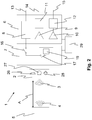
- FIG. 1 1 shows a block diagram of a loudspeaker unit 1.
- the loudspeaker unit 1 comprises a MEMS sound transducer 2 by means of which sound waves 3, 4 can be generated and detected during operation of the loudspeaker unit 1.
- the speaker unit 1 can thus be a sound converter unit.
- the speaker unit 1 can be arranged, for example, in a portable device, such as a smartphone, a tablet or the like, in order to play music, speech or sounds.
- the MEMS sound transducer 2 can thus be operated as a loudspeaker 26. With the help of the MEMS sound transducer 2 but also a language, sounds or music can be recorded, so that the MEMS sound transducer 2 is operated as a microphone 27.
- the speaker unit 1 for example in a smartphone, so can be phoned for example.
- the MEMS sound transducer 2 can additionally be operated as an ultrasonic proximity sensor 28 in order to be able to measure a distance A between itself and an object 5.
- the MEMS sound transducer 2 can emit ultrasonic waves which are reflected by the object 5 and return to the MEMS sound transducer 2 by which they are detected. Based on a transit time of the ultrasonic waves, the distance A between the object 5 and the MEMS sound transducer 2 can be determined.
- the loudspeaker unit 1 has a processing unit 6 which can, for example, prepare an audio signal for the MEMS sound transducer 2 for playback. Additionally or alternatively, the processing unit 6 can also process the sound waves detected by the MEMS sound transducer 2.
- the loudspeaker unit 1 has a loudspeaker amplifier 8.
- the speaker amplifier 8 is in the present embodiment of the FIG. 1 arranged in the processing unit 6. With the help of the loudspeaker amplifier 8, the audio signal intended for output at the MEMS sound transducer 2 can be amplified and / or processed.
- the loudspeaker unit 1 can have at least one microphone amplifier 9, 10.
- the at least one microphone amplifier 9, 10 the sound waves detected by the MEMS sound transducer 2 can be amplified and / or processed.
- the at least one microphone amplifier 9, 10 is in the embodiment of FIG. 1 arranged in the processing unit 6.
- the loudspeaker unit 1 has a first and a second microphone amplifier 9, 10.
- One of the two microphone amplifiers 9, 10 can be designed to amplify and / or to process a sound signal contained in the detected sound waves.
- the sound signal may include, for example, speech, sounds and / or music.
- the sound signal thus comprises audible sound waves or comprises an electrical signal having the audible sound waves.
- the other microphone amplifier 9, 10 may be designed to amplify and / or process a distance signal contained in the detected sound waves. Since the MEMS sound transducer 2 emits ultrasonic waves for determining the distance A, the detected sound waves likewise have ultrasonic waves, by means of which the distance 5 is determined. The said microphone amplifier 9, 10 can thus amplify and / or process the ultrasonic waves contained in the detected sound waves.
- the loudspeaker unit 1 can have at least one processing unit 11, 12.
- the sound signals in particular the sound signals and / or the distance signal, can be processed.
- the sound signals can be digitized and / or filtered by the at least one processing unit 11, 12, for example.
- the loudspeaker unit 1 has two processing units 11, 12.
- the first processing unit 11 may be connected downstream of the first microphone amplifier 9.
- the sound signal processed by the first microphone amplifier 9, in particular the sound signal, can thus be conducted to the first processing unit 11.
- the second processing unit 12 may be connected downstream of the second microphone amplifier 10.
- the sound signal processed by the second microphone amplifier 10, in particular the distance signal, can thus be conducted to the second amplifier unit 12.
- the loudspeaker unit 1 advantageously has at least one input 13 via which, for example, an audio signal for generating corresponding sound waves can be supplied to the MEMS sound transducer 2.
- the speaker unit 1 has at least one output 14, 15.
- the speaker unit 1 according to the present embodiment has two outputs 14, 15.
- the first output 14 is connected to the first processing unit 11 and via this to the first microphone amplifier 9.
- the first output 14 may also be connected directly to the first microphone amplifier 9.
- the sound signal can be discharged via the first output 14.
- the sound signal can thus be stored or forwarded, for example.
- the sound signal can then be sent to a call partner, for example, if the loudspeaker unit 1 is arranged in a smartphone or a telephone and used for this purpose.
- the loudspeaker unit 1 has the second output 15, via which the distance signal can be led out of the loudspeaker unit 1.
- the distance signal can then be routed to another unit.
- the distance signal can be further processed, for example, in the smartphone.
- the second output 15 can also be followed by an evaluation unit, not shown here, which evaluates the distance signal.
- the loudspeaker unit 1 has a switching unit 7, by means of which a connection between the MEMS sound transducer 2 and the processing unit 6 can be established.
- a connection can also be formed between the MEMS sound transducer 2 and the loudspeaker amplifier 8 and / or the first and / or the second microphone amplifier 9, 10 by means of the switching unit 7.
- a connection between the MEMS sound transducer 2 and the first and / or second processing unit 11, 12 may be formed.
- the switching unit 7 has at least one switch 16-18, with which a connection between the MEMS sound transducer 2 and the processing unit 6 can be formed.
- the switching unit 7 of FIG. 1 has three switches 16-18.
- a connection between the MEMS sound transducer 2 and the loudspeaker amplifier 8 can be formed with the aid of the first switch 16 so that the audio signal can be conducted to the MEMS sound transducer 2 for output.
- the switching unit 7 has a second switch 17, by means of which a connection between the MEMS sound transducer 2 and the first microphone amplifier 9 can be formed in the present exemplary embodiment. Additionally or alternatively, a connection between the MEMS sound transducer 2 and the first processing unit 11 can also be formed with the aid of the second switch 17.
- the switching unit 7 has a third switch 18, by means of which a connection between the MEMS sound transducer 2 and the second microphone amplifier 10 is formed in the present exemplary embodiment. Additionally or alternatively, with the help of the third Switch 18, a connection between the MEMS transducer 2 and the second processing unit 12 are formed.
- the three switches 16-18 of the present embodiment can be opened and closed independently of each other. That is, only one switch 16-18 can be closed at any one time, whereas the other two are open. Alternatively, two switches 16 - 18, wherein the corresponding remaining switch 16 - 18 is opened, or all three switches 16-18 be closed. Alternatively, all three switches 16 - 18 may be open.
- the speaker unit 1 may comprise a control unit 29.
- the control unit 29 may be connected to the switching unit 7 according to the present embodiment. Additionally or alternatively, as shown in the present embodiment, the control unit 29 may also be connected to the processing unit 6.
- the control unit 29 can, for example, switch at least one of the switches 16 - 18 of the switching unit 7. Additionally or alternatively, the control unit 29 may also control the loudspeaker amplifier 6, at least one of the microphone amplifiers 9, 10 and / or at least one processing unit 11, 12 of the processing unit.
- the loudspeaker unit 1 of the present embodiment has an evaluation unit 30.
- the distance A a temporal change of the distance A and / or a distance profile can be evaluated in order to recognize, for example, gestures or a shape of the object 5 can.
- a smartphone can be activated with the wiping movement if the loudspeaker unit 1 and the MEMS sound transducer 2 are arranged in a smartphone.
- FIG. 2 shows a block diagram of a speaker unit 1 according to an alternative embodiment. For the sake of simplicity, the features identical to FIG. 1 will not be discussed again.
- the first switch 16 connects the MEMS sound transducer 2 to the loudspeaker amplifier 8, so that the audio signal intended for output, which can be amplified and / or processed by the loudspeaker amplifier 8, can be conducted to the MEMS sound transducer 2.
- the crossover 19 is further connected to the first and the second microphone amplifier 9, 10, so that via the crossover 19, the sound signal detected by the MEMS transducer 2 to the two microphone amplifiers 9, 10 can be passed.
- the crossover 19 may be designed such that the sound signal having frequencies in the audible wavelength spectrum, is passed to the first microphone amplifier 9 and that the distance signal having frequencies in the ultrasonic range, is passed to the second microphone amplifier 10.
- the crossover 19 may, for example, to have an arrangement of high passes, low passes and / or bandpasses. As a result, the sound signal and the distance signal can be separated from one another in a simple manner from the sound signal.
- FIG. 3 shows a timing diagram 20 of operating conditions of the speaker unit 1. On the x-axis, the time is t and along the y-axis, the various intervals are plotted.
- the timing diagram 20 has a period 21, which may represent a tact time, according to which the speaker unit 1 can be operated.
- the period 21 may be repeated and have a constant duration.
- the period 21 can last between 0.1 ⁇ s and 10 ms.
- the period 21 may take between 0.5 ⁇ s and 5 ms.
- the period of a period 21 may be constant or variable. For example, two consecutive periods 21 may have a different duration.
- a period 21 may further be divided into a loudspeaker interval 22 and a microphone interval 23.
- the microphone interval 23 follows the loudspeaker interval 22.
- the loudspeaker interval 22 can also be followed by the microphone interval 23.
- the loudspeaker unit 1 is operated as a loudspeaker 26. That is, during the loudspeaker interval 22, the MEMS sound transducer 2 is operated to generate sound waves 3. During the loudspeaker interval 22, sounds, sounds and speech can thus be generated. In addition, during the loudspeaker interval 22, the ultrasonic waves for measuring the distance A may be generated.
- the MEMS sound transducer 2 can be connected to the loudspeaker amplifier 8, so that the audio signal provided for output by the MEMS sound transducer 2 can be routed to it. By the loudspeaker amplifier 8, the audio signal can be processed and / or amplified.
- the speaker unit 1 can be operated such that sound waves can be detected.
- the MEMS sound transducer 2 can thus be operated in such a way that sound waves from the surroundings of the loudspeaker unit 1 are detected.
- the MEMS sound transducer 2 is in the microphone interval 23 as a microphone 27th operated.
- the detected sound waves can be conducted, for example in the form of the sound signal, to at least one microphone amplifier 9, 10.
- the at least one microphone amplifier 9, 10 the sound signal can be amplified and / or edited.
- the switching unit 7 can switch accordingly.
- the second switch 17 and / or the third switch 18 can be closed to direct the sound signal to the corresponding microphone amplifier 9, 10.
- the ultrasonic waves reflected by the object 5 can also be detected and directed to the corresponding microphone amplifier 9, 10.
- the loudspeaker interval 22 may have a sound interval 24 and an ultrasound interval 25.
- the ultrasonic interval 25 follows the sound interval 24.
- the ultrasonic interval 25 may also be arranged first and the sound interval 24 may follow in time.
- the MEMS transducer 2 may be operated to generate sound waves in the audible wave spectrum range, such as music, sound, and / or speech.
- the MEMS transducer 2 may be operated to generate ultrasonic waves and / or the ultrasonic signal to measure the distance A between the object 5 and the MEMS transducer 2.
- the microphone interval 23 follows the ultrasound interval 25.
- the ultrasonic waves emitted during the ultrasonic interval 25 and sound waves 4 reflected at the object 5 can be detected during the microphone interval 23. From a time interval between the emission of the ultrasonic waves and the detection of the object 5 reflected sound waves 4, the distance A between the MEMS transducer 2 and the object 5 can be determined.
- the ultrasonic waves can also be modulated to the sound waves in the audible wavelength range.
- the ultrasonic waves are thus modulated to the music, to the sounds and / or to the language. Since the ultrasonic waves have higher frequencies than the music, the sounds and / or the voice, this does not affect the sound quality of the music, the sounds and / or the language. Thereby, the ultrasonic waves can be generated simultaneously with the sound waves of the audible wavelength range during the loudspeaker interval 22.
Landscapes
- Engineering & Computer Science (AREA)
- Physics & Mathematics (AREA)
- Acoustics & Sound (AREA)
- Signal Processing (AREA)
- Remote Sensing (AREA)
- Radar, Positioning & Navigation (AREA)
- Theoretical Computer Science (AREA)
- General Physics & Mathematics (AREA)
- General Engineering & Computer Science (AREA)
- Computer Hardware Design (AREA)
- Human Computer Interaction (AREA)
- Computer Networks & Wireless Communication (AREA)
- Health & Medical Sciences (AREA)
- General Health & Medical Sciences (AREA)
- Otolaryngology (AREA)
- Audiology, Speech & Language Pathology (AREA)
- Multimedia (AREA)
- Measurement Of Velocity Or Position Using Acoustic Or Ultrasonic Waves (AREA)
- Telephone Function (AREA)
- Transducers For Ultrasonic Waves (AREA)
- Circuit For Audible Band Transducer (AREA)
Applications Claiming Priority (1)
| Application Number | Priority Date | Filing Date | Title |
|---|---|---|---|
| DE102018113112.7A DE102018113112A1 (de) | 2018-06-01 | 2018-06-01 | Verfahren zum Betreiben einer Lautsprechereinheit sowie eine Lautsprechereinheit |
Publications (1)
| Publication Number | Publication Date |
|---|---|
| EP3576431A1 true EP3576431A1 (fr) | 2019-12-04 |
Family
ID=66655276
Family Applications (1)
| Application Number | Title | Priority Date | Filing Date |
|---|---|---|---|
| EP19176818.3A Withdrawn EP3576431A1 (fr) | 2018-06-01 | 2019-05-27 | Procédé de fonctionnement d'une unité de haut-parleur ainsi qu'unité de haut-parleur |
Country Status (9)
| Country | Link |
|---|---|
| US (1) | US20190369236A1 (fr) |
| EP (1) | EP3576431A1 (fr) |
| KR (1) | KR20190137710A (fr) |
| CN (1) | CN110557706A (fr) |
| AU (1) | AU2019203711A1 (fr) |
| CA (1) | CA3044792A1 (fr) |
| DE (1) | DE102018113112A1 (fr) |
| SG (1) | SG10201904865VA (fr) |
| TW (1) | TW202005418A (fr) |
Families Citing this family (10)
| Publication number | Priority date | Publication date | Assignee | Title |
|---|---|---|---|---|
| CN111161523A (zh) * | 2019-12-31 | 2020-05-15 | 联想(北京)有限公司 | 一种处理方法及装置 |
| DE102020200759A1 (de) | 2020-01-22 | 2021-07-22 | Brose Fahrzeugteile Se & Co. Kommanditgesellschaft, Bamberg | Verfahren zum Betrieb eines Ultraschallsensors eines Kraftfahrzeugs |
| CN111790644B (zh) * | 2020-07-22 | 2022-03-25 | 贵阳力创自动化设备有限公司 | 一种自动阻抗声压测试机控制系统 |
| CN115050381B (zh) * | 2021-03-08 | 2025-12-02 | 瑞昱半导体股份有限公司 | 基于超声波的音频播放方法及基于超声波的电子装置 |
| US12277294B2 (en) | 2021-09-16 | 2025-04-15 | Goertek Inc. | Acoustic input apparatus and method, electronic device and computer-readable medium |
| US12192704B2 (en) | 2021-12-14 | 2025-01-07 | Invensense, Inc. | Microelectromechanical system microphone array capsule |
| CN117354412A (zh) * | 2022-06-27 | 2024-01-05 | 北京小米移动软件有限公司 | 语音通话处理方法、电路、装置、介质、芯片和终端 |
| US12388538B2 (en) | 2022-07-28 | 2025-08-12 | Invensense, Inc. | Utilization of microphone ultrasonic response |
| US12604129B2 (en) | 2022-10-07 | 2026-04-14 | Fortemedia, Inc. | True wireless device and dual-mode true wireless device |
| EP4354179B1 (fr) | 2022-10-13 | 2025-07-23 | Axis AB | Système et procédé pour déterminer une distance entre des dispositifs électroniques en réseau comprenant chacun un haut-parleur et un microphone |
Citations (10)
| Publication number | Priority date | Publication date | Assignee | Title |
|---|---|---|---|---|
| WO2008128989A1 (fr) * | 2007-04-19 | 2008-10-30 | Epos Technologies Limited | Localisation vocale et de position |
| EP2271134A1 (fr) * | 2009-07-02 | 2011-01-05 | Nxp B.V. | Capteur de proximité comprenant un transducteur acoustique pour la réception de signaux sonores dans la gamme audible humaine et pour la émission et réception des signaux ultrasoniques. |
| WO2012123787A1 (fr) * | 2011-03-14 | 2012-09-20 | Nokia Corporation | Appareil d'écholocalisation |
| US20140140551A1 (en) * | 2012-11-21 | 2014-05-22 | Strategic Polymer Sciences, Inc. | System of Audio Speakers Implemented Using EMP Actuators |
| US20160345113A1 (en) * | 2015-05-22 | 2016-11-24 | Samsung Electronics Co., Ltd. | Method of recognizing surrounding environment and electronic device for the same |
| US20170064457A1 (en) * | 2015-03-25 | 2017-03-02 | Dsp Group Ltd. | Generation of audio and ultrasonic signals and measuring ultrasonic response in dual-mode mems speaker |
| DE102015114245A1 (de) | 2015-08-27 | 2017-03-02 | USound GmbH | MEMS-Schallwandler mit geschlossenem Regelsystem |
| WO2017137755A2 (fr) * | 2016-02-09 | 2017-08-17 | Elliptic Laboratories As | Détection de proximité |
| WO2018026657A1 (fr) * | 2016-08-02 | 2018-02-08 | Knowles Electronics, Llc | Transducteur à ultrasons à système microélectromécanique |
| US20190341955A1 (en) * | 2018-05-04 | 2019-11-07 | Microsoft Technology Licensing, Llc | Ultrasonic proximity sensing for sar mitigation |
Family Cites Families (6)
| Publication number | Priority date | Publication date | Assignee | Title |
|---|---|---|---|---|
| US9810784B2 (en) * | 2010-11-16 | 2017-11-07 | Qualcomm Incorporated | System and method for object position estimation based on ultrasonic reflected signals |
| US8941619B2 (en) * | 2011-11-18 | 2015-01-27 | Au Optronics Corporation | Apparatus and method for controlling information display |
| CN107076840A (zh) * | 2014-10-02 | 2017-08-18 | 美商楼氏电子有限公司 | 具有双mems装置的声学设备 |
| WO2016106154A1 (fr) * | 2014-12-21 | 2016-06-30 | Chirp Microsystems, Inc. | Télémètre ultrasonore d'antenne à rayonnement longitudinal différentiel |
| WO2016129987A1 (fr) * | 2015-02-11 | 2016-08-18 | Knowles Ipc (M) Sdn. Bhd. | Transducteur électrodynamique en mode ultrasonore |
| CN106598293B (zh) * | 2016-12-14 | 2019-09-06 | 吉林大学 | 一种三维大空间多通道笔式交互系统 |
-
2018
- 2018-06-01 DE DE102018113112.7A patent/DE102018113112A1/de active Pending
-
2019
- 2019-05-07 TW TW108115785A patent/TW202005418A/zh unknown
- 2019-05-27 EP EP19176818.3A patent/EP3576431A1/fr not_active Withdrawn
- 2019-05-28 CN CN201910449646.0A patent/CN110557706A/zh active Pending
- 2019-05-28 AU AU2019203711A patent/AU2019203711A1/en not_active Abandoned
- 2019-05-29 SG SG10201904865VA patent/SG10201904865VA/en unknown
- 2019-05-29 CA CA3044792A patent/CA3044792A1/fr not_active Abandoned
- 2019-05-30 US US16/426,594 patent/US20190369236A1/en not_active Abandoned
- 2019-05-31 KR KR1020190064295A patent/KR20190137710A/ko not_active Withdrawn
Patent Citations (10)
| Publication number | Priority date | Publication date | Assignee | Title |
|---|---|---|---|---|
| WO2008128989A1 (fr) * | 2007-04-19 | 2008-10-30 | Epos Technologies Limited | Localisation vocale et de position |
| EP2271134A1 (fr) * | 2009-07-02 | 2011-01-05 | Nxp B.V. | Capteur de proximité comprenant un transducteur acoustique pour la réception de signaux sonores dans la gamme audible humaine et pour la émission et réception des signaux ultrasoniques. |
| WO2012123787A1 (fr) * | 2011-03-14 | 2012-09-20 | Nokia Corporation | Appareil d'écholocalisation |
| US20140140551A1 (en) * | 2012-11-21 | 2014-05-22 | Strategic Polymer Sciences, Inc. | System of Audio Speakers Implemented Using EMP Actuators |
| US20170064457A1 (en) * | 2015-03-25 | 2017-03-02 | Dsp Group Ltd. | Generation of audio and ultrasonic signals and measuring ultrasonic response in dual-mode mems speaker |
| US20160345113A1 (en) * | 2015-05-22 | 2016-11-24 | Samsung Electronics Co., Ltd. | Method of recognizing surrounding environment and electronic device for the same |
| DE102015114245A1 (de) | 2015-08-27 | 2017-03-02 | USound GmbH | MEMS-Schallwandler mit geschlossenem Regelsystem |
| WO2017137755A2 (fr) * | 2016-02-09 | 2017-08-17 | Elliptic Laboratories As | Détection de proximité |
| WO2018026657A1 (fr) * | 2016-08-02 | 2018-02-08 | Knowles Electronics, Llc | Transducteur à ultrasons à système microélectromécanique |
| US20190341955A1 (en) * | 2018-05-04 | 2019-11-07 | Microsoft Technology Licensing, Llc | Ultrasonic proximity sensing for sar mitigation |
Also Published As
| Publication number | Publication date |
|---|---|
| DE102018113112A1 (de) | 2019-12-05 |
| US20190369236A1 (en) | 2019-12-05 |
| KR20190137710A (ko) | 2019-12-11 |
| AU2019203711A1 (en) | 2019-12-19 |
| CN110557706A (zh) | 2019-12-10 |
| CA3044792A1 (fr) | 2019-12-01 |
| TW202005418A (zh) | 2020-01-16 |
| SG10201904865VA (en) | 2020-01-30 |
Similar Documents
| Publication | Publication Date | Title |
|---|---|---|
| EP3576431A1 (fr) | Procédé de fonctionnement d'une unité de haut-parleur ainsi qu'unité de haut-parleur | |
| DE102009051508B4 (de) | Vorrichtung, System und Verfahren zur Sprachdialogaktivierung und -führung | |
| WO1999049698A1 (fr) | Procede et dispositif permettant de faire fonctionner un systeme microphone, notamment dans un vehicule | |
| DE102008054789A1 (de) | Verfahren und Vorrichtung zum Verstärken eines zur Fahrzeugumfelddetektion geeigneten Signals | |
| DE102013002963A1 (de) | Steuerung unter Anwendung zeitlich und/oder spektral kompakter Audiobefehle | |
| EP3454572A1 (fr) | Procédé de reconnaissance d'un défaut dans un appareil auditif | |
| DE10208096A1 (de) | Mobiles Kommunikationsendgerät | |
| EP3490270A1 (fr) | Procédé de fonctionnement d'un dispositif de correction auditive | |
| DE102008046040A1 (de) | Verfahren zum Betrieb einer Hörvorrichtung mit Richtwirkung und zugehörige Hörvorrichtung | |
| WO2001047335A2 (fr) | Procede pour eliminer des composantes de signaux parasites dans un signal d'entree d'un systeme auditif, mise en oeuvre dudit procede et appareil auditif | |
| EP4093052A1 (fr) | Procédé et dispositif de traitement sélectif en fréquence d'un signal audio à faible latence | |
| EP3232691B1 (fr) | Procédé de détermination de la réponse d'impulsion spatiale d'un habitacle d'un véhicule automobile | |
| DE69224680T2 (de) | Elektroakustische Verstärker-Anordnung und Mikrofonanordnung zur Verwendung in der elektroakustischen Verstärker-Anordnung | |
| EP2326969A1 (fr) | Procédé et dispositif de commande de capteurs sur un véhicule | |
| EP1808853A1 (fr) | Dispositif et procédé pour améliorer l'intelligibilité d'un système de sonorisation, et programme informatique | |
| EP2801085B1 (fr) | Dispositif de détection de signaux analogiques et procédé permettant de faire fonctionner ledit dispositif | |
| DE10321625B4 (de) | Signalübertragungsvorrichtung und Verfahren zum Regeln einer Signalübertragungsvorrichtung | |
| DE19620031C1 (de) | Verfahren zur automatischen Justierung einer Schalteinrichtung zum automatischen Umschalten zwischen einer Empfangsbetriebsart und einer Sendebetriebsart bei einer Freisprecheinrichtung eines Kommunikationsendgerätes | |
| EP3337183A1 (fr) | Procédé et agencement de circuit destinés au fonctionnement d'un casque d'écoute | |
| EP1359437A1 (fr) | Procédé pour déterminer la position d'un utilisateur de terminal de communication | |
| DE10320209B4 (de) | Audiosignal-Erkennungssystem | |
| DE102018112597A1 (de) | Verfahren zum Betreiben einer Ultraschallsensorvorrichtung für ein Kraftfahrzeug, wobei zwei Ultraschallsignale zumindest teilweise gleichzeitig ausgesendet werden, Ultraschallsensorvorrichtung sowie Kraftfahrzeug | |
| DE102023202367A1 (de) | Verfahren zum Betrieb eines Hörgerätes, Hörgerät und Computerprogrammprodukt | |
| WO2015176986A1 (fr) | Procédé d'exploitation d'un système de dialogue vocal pour véhicule automobile | |
| DE102021204939A1 (de) | Verfahren und Vorrichtung zur Erkennung der Passgenauigkeit von Kopfhörern |
Legal Events
| Date | Code | Title | Description |
|---|---|---|---|
| PUAI | Public reference made under article 153(3) epc to a published international application that has entered the european phase |
Free format text: ORIGINAL CODE: 0009012 |
|
| STAA | Information on the status of an ep patent application or granted ep patent |
Free format text: STATUS: THE APPLICATION HAS BEEN PUBLISHED |
|
| AK | Designated contracting states |
Kind code of ref document: A1 Designated state(s): AL AT BE BG CH CY CZ DE DK EE ES FI FR GB GR HR HU IE IS IT LI LT LU LV MC MK MT NL NO PL PT RO RS SE SI SK SM TR |
|
| AX | Request for extension of the european patent |
Extension state: BA ME |
|
| STAA | Information on the status of an ep patent application or granted ep patent |
Free format text: STATUS: REQUEST FOR EXAMINATION WAS MADE |
|
| 17P | Request for examination filed |
Effective date: 20200604 |
|
| RBV | Designated contracting states (corrected) |
Designated state(s): AL AT BE BG CH CY CZ DE DK EE ES FI FR GB GR HR HU IE IS IT LI LT LU LV MC MK MT NL NO PL PT RO RS SE SI SK SM TR |
|
| STAA | Information on the status of an ep patent application or granted ep patent |
Free format text: STATUS: EXAMINATION IS IN PROGRESS |
|
| 17Q | First examination report despatched |
Effective date: 20200810 |
|
| STAA | Information on the status of an ep patent application or granted ep patent |
Free format text: STATUS: THE APPLICATION HAS BEEN WITHDRAWN |
|
| 18W | Application withdrawn |
Effective date: 20230616 |