EP3576511B1 - Dispositif et procédé de commande, et dispositif de montage - Google Patents
Dispositif et procédé de commande, et dispositif de montage Download PDFInfo
- Publication number
- EP3576511B1 EP3576511B1 EP17893955.9A EP17893955A EP3576511B1 EP 3576511 B1 EP3576511 B1 EP 3576511B1 EP 17893955 A EP17893955 A EP 17893955A EP 3576511 B1 EP3576511 B1 EP 3576511B1
- Authority
- EP
- European Patent Office
- Prior art keywords
- pickup
- mounting
- section
- nozzle
- pickup members
- Prior art date
- Legal status (The legal status is an assumption and is not a legal conclusion. Google has not performed a legal analysis and makes no representation as to the accuracy of the status listed.)
- Active
Links
Images


Classifications
-
- H—ELECTRICITY
- H05—ELECTRIC TECHNIQUES NOT OTHERWISE PROVIDED FOR
- H05K—PRINTED CIRCUITS; CASINGS OR CONSTRUCTIONAL DETAILS OF ELECTRIC APPARATUS; MANUFACTURE OF ASSEMBLAGES OF ELECTRICAL COMPONENTS
- H05K13/00—Apparatus or processes specially adapted for manufacturing or adjusting assemblages of electric components
- H05K13/08—Monitoring manufacture of assemblages
- H05K13/0882—Control systems for mounting machines or assembly lines, e.g. centralized control, remote links, programming of apparatus and processes as such
-
- H—ELECTRICITY
- H05—ELECTRIC TECHNIQUES NOT OTHERWISE PROVIDED FOR
- H05K—PRINTED CIRCUITS; CASINGS OR CONSTRUCTIONAL DETAILS OF ELECTRIC APPARATUS; MANUFACTURE OF ASSEMBLAGES OF ELECTRICAL COMPONENTS
- H05K13/00—Apparatus or processes specially adapted for manufacturing or adjusting assemblages of electric components
- H05K13/02—Feeding of components
-
- H—ELECTRICITY
- H05—ELECTRIC TECHNIQUES NOT OTHERWISE PROVIDED FOR
- H05K—PRINTED CIRCUITS; CASINGS OR CONSTRUCTIONAL DETAILS OF ELECTRIC APPARATUS; MANUFACTURE OF ASSEMBLAGES OF ELECTRICAL COMPONENTS
- H05K13/00—Apparatus or processes specially adapted for manufacturing or adjusting assemblages of electric components
- H05K13/04—Mounting of components, e.g. of leadless components
-
- H—ELECTRICITY
- H05—ELECTRIC TECHNIQUES NOT OTHERWISE PROVIDED FOR
- H05K—PRINTED CIRCUITS; CASINGS OR CONSTRUCTIONAL DETAILS OF ELECTRIC APPARATUS; MANUFACTURE OF ASSEMBLAGES OF ELECTRICAL COMPONENTS
- H05K13/00—Apparatus or processes specially adapted for manufacturing or adjusting assemblages of electric components
- H05K13/04—Mounting of components, e.g. of leadless components
- H05K13/0404—Pick-and-place heads or apparatus, e.g. with jaws
- H05K13/0408—Incorporating a pick-up tool
- H05K13/041—Incorporating a pick-up tool having multiple pick-up tools
-
- H—ELECTRICITY
- H05—ELECTRIC TECHNIQUES NOT OTHERWISE PROVIDED FOR
- H05K—PRINTED CIRCUITS; CASINGS OR CONSTRUCTIONAL DETAILS OF ELECTRIC APPARATUS; MANUFACTURE OF ASSEMBLAGES OF ELECTRICAL COMPONENTS
- H05K13/00—Apparatus or processes specially adapted for manufacturing or adjusting assemblages of electric components
- H05K13/04—Mounting of components, e.g. of leadless components
- H05K13/0478—Simultaneously mounting of different components
-
- H—ELECTRICITY
- H05—ELECTRIC TECHNIQUES NOT OTHERWISE PROVIDED FOR
- H05K—PRINTED CIRCUITS; CASINGS OR CONSTRUCTIONAL DETAILS OF ELECTRIC APPARATUS; MANUFACTURE OF ASSEMBLAGES OF ELECTRICAL COMPONENTS
- H05K13/00—Apparatus or processes specially adapted for manufacturing or adjusting assemblages of electric components
- H05K13/08—Monitoring manufacture of assemblages
- H05K13/081—Integration of optical monitoring devices in assembly lines; Processes using optical monitoring devices specially adapted for controlling devices or machines in assembly lines
-
- H—ELECTRICITY
- H05—ELECTRIC TECHNIQUES NOT OTHERWISE PROVIDED FOR
- H05K—PRINTED CIRCUITS; CASINGS OR CONSTRUCTIONAL DETAILS OF ELECTRIC APPARATUS; MANUFACTURE OF ASSEMBLAGES OF ELECTRICAL COMPONENTS
- H05K13/00—Apparatus or processes specially adapted for manufacturing or adjusting assemblages of electric components
- H05K13/04—Mounting of components, e.g. of leadless components
- H05K13/0417—Feeding with belts or tapes
- H05K13/0419—Feeding with belts or tapes tape feeders
Definitions
- the present disclosure which is an invention disclosed in this description, relates to a control device, a mounting device, and a control method.
- a mounting device for example, there has been proposed a mounting device in which a rotational axis position of each of multiple suction nozzles is detected, a positional deviation amount between each rotational axis position and a nozzle tip is detected, each nozzle tip is rotated based on the information on the positional deviation amount, and a tip center position of each suction nozzle and a pickup position of a corresponding electronic component are moved relatively (for example, refer to Patent Literature 1 disclosing the preambles of independent claims 1 and 7).
- Patent Literature 1 disclosing the preambles of independent claims 1 and 7.
- electronic components can be picked up simultaneously without errors and properly.
- Further examples of devices and methods for mounting components are disclosed in EP 1 187 524 A2 , WO 2014/188564 A1 and WO 2013/140600 A1 .
- Patent Literature 1 JP 2007 189041 A
- This disclosure has been made in view of the problem described above, and a main object of the invention is to provide a control device, a mounting device, and a control method that enable multiple components to be picked up in the same process in a more ensured manner.
- the present invention provides a control device, a mounting device, and a control method according to independent claims 1, 3 and 7, respectively. Preferred embodiments are laid down in the dependent claims.
- the control device selects the combination of the pickup members in which the distance between the tips of the pickup members that is obtained based on the first deviation amount of the first pickup member and the second deviation amount of the second pickup member falls within the predetermined range.
- the "predetermined range” may be determined based on, for example, an interval at which components are supplied by the component supply section, and more specifically, the predetermined range may be determined to be an interval range where multiple components can be picked up without moving the mounting head.
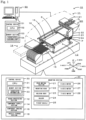
- Fig. 1 is a schematic explanatory diagram showing an example of a mounting system 10 according to the present disclosure.
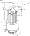
- Fig. 2 is an explanatory diagram of mounting head 22.
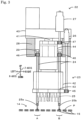
- Fig. 3 is an explanatory diagram showing mounting head 22 picking up components P simultaneously.
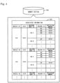
- Fig. 4 is an explanatory diagram illustrating an example of associated pieces of information 33 stored in memory section 32.
- Mounting system 10 is, for example, a system configured to execute a mounting process of mounting a component P on a board S.
- This mounting system 10 includes mounting device 11 and management computer (PC) 50.
- Mounting system 10 is configured as a mounting line along which multiple mounting devices 11 are disposed from an upstream to a downstream thereof.
- PC management computer
- Mounting section 20 picks up a component P from component supply section 14 to dispose the component P on board S fixed to board processing section 12.
- Mounting section 20 includes head moving section 21, mounting head 22, holding body 23, nozzle holders 24, and suction nozzles 25.
- Head moving section 21 includes sliders, which are guided by respective guide rails to move in X and Y directions, and motors configured to drive the respective sliders.
- Mounting head 22 is detachably mounted on the slider, and when the head moving section 21 moves, the mounting head 22 can move in the X and Y directions accordingly.
- One or more suction nozzles 25 are detachably mounted on a lower surface of mounting head 22 via holding body 23. Multiple suction nozzles 25 of any type of the multiple types are mounted on holding body 23.
- Head main body 40 includes R-axis motor 26 configured to axially rotate rotary section 42, Q-axis motor 27 configured to axially rotate suction nozzles 25, and Z-axis motor 28 configured to move push-down section 29 to thereby raise or lower suction nozzles 25.
- Rotation axis of rotary section 42 is referred to as an R-axis
- a rotation axis of suction nozzle 25 is referred to as a Q-axis.
- Engagement shaft 41 is provided on head main body 40 in such a manner as to axially rotate and is inserted into a bottomed hole formed at a center of Q-axis gear 44 to thereby be brought into engagement with holding body 23.
- Nozzle holder 24 is a member including small gear 46 provided at an upper end side thereof and suction nozzle 25 provided at a lower end side thereof. Small gear 46 is in mesh engagement with the gear grooves formed on an outer circumference of Q-axis gear 44. Nozzle holders 24 are disposed at equal intervals along the outer circumference of Q-axis gear 44. Nozzle holder 24 rotates (on its own axis) around its own rotation axis (Q-axis) by a driving force of Q-axis motor 27, being transmitted by way of small gear 47 connected to Q-axis motor 27, Q-axis gear 44, and small gear 46 provided at the upper end side of nozzle holder 24, and controls an angle of a component P that is picked up.
- Management PC 50 is a computer configured to manage information on the constituent devices of mounting system 10. As shown in Fig. 1 , management PC50 includes control device 51, memory section 53, a display, and an input device.
- Control device 51 is configured as a microprocessor including mainly CPU 52 that functions as a control section.
- Memory section 53 is a device such as HDD configured to store various types of data such as processing programs.
- the display is a liquid crystal screen configured to display various types of information thereon.
- the input device includes a keyboard, a mouse, and the like through which an operator inputs various types of commands.
- Memory section 53 stores associated information 54 similar to associated information 33 stored in memory section 32.
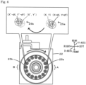
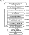
- CPU31 selects a combination of suction nozzles 25 facing each other based on the criteria described above using the deviation amounts at nozzle holders 24 where suction nozzles 25 are mounted.
- CPU31 may cancel the simultaneous pick up of components P for suction nozzles 25 that are located in first lifting and lowering position A and second lifting and lowering position B.
- CPU31 causes the current combination of suction nozzles 25 to be replaced with the selected combination of suction nozzles 25 (S180 ).
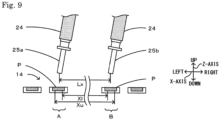
- Fig. 9 is an explanatory diagram illustrating a state where although suction nozzles 25 deviate, the interval Lx stays within the predetermined range.
- mounting device 11 since the combination of suction nozzles 25 in which the nozzle tip interval falls within the predetermined range is selected and suction nozzles 25 so selected are mounted on mounting head 22, more suitable suction nozzles 25 can be selected for mounting on mounting head 22, whereby multiple components P can be picked up within the same process in a more ensured manner.
- component imaging section 16 is caused to image mounting head 22 on which suction nozzles 25 are mounted, and the deviation amounts at the tips of suction nozzles 25 are acquired based on the captured image, whereby the deviation amounts at the tips of suction nozzles 25 can be measured using the captured image.
- nozzle holders 24 on mounting head 22 are described as axially rotating in synchronism with one another, the disclosure is not particularly limited to this configuration, and hence, nozzle holders 24 may axially rotate separately or individually. However, the configuration in which all nozzle holders 24 axially rotate in synchronism with one another is more significant and preferred in terms of application of the contents of this disclosure.
- control section may be configured to output for display the selected combination of pickup members.
- the operator can confirm the combination of pickup members so outputted and displayed and hence, for example, the operator can set preferred combinations of pickup members in advance.
- the control device disclosed in this description may have a configuration in which the control device includes a memory section, and the control section acquires identification information of the pickup members, identification information of the holders indicating the deviation amounts, and tip deviation amounts of the pickup members and stores the identification information on the pickup members, the identification information on the holders, and the tip deviation amounts of the pickup members that are so acquired in the memory section as associated information where those pieces of information and the tip deviation amounts are associated with one another.
- the control device by managing the associated information, for example, combinations of pickup members which can pick up components within the same process can be selected in advance.
- measuring deviation amounts can be omitted by using the associated information stored in advance.
- the control section may select the combination of pickup members in which the tip interval of the pickup members falls within the predetermined range by using the associated information.
- a mounting device disclosed in this description may include: a mounting head including at least a first holder installing a first pickup member and a second holder installing a second pickup member; a component supply section configured to supply components to the mounting head; and any one of the control devices described above.
- a configuration may be adopted in which the control section determines whether a tip intervals of the pickup members falls within a predetermined range, and when determining that the tip interval falls within the predetermined range, the control section causes the mounting head to pick up the components from the component supply section using the first pickup member and the second pickup member within the same process. According to this mounting device, multiple components can be picked up within the same process in a more ensured manner.
- the control section acquires a first deviation amount of the tip of the first pickup member and a deviation amount at the tip of the second pickup member, selects a combination of pickup members in which a tip interval between the pickup members that is obtained based on the first deviation amount and the second deviation amount falls within the predetermined range, and mounts the selected combination of pickup members on the mounting head.
- this mounting device since a more suitable combination of pickup members can be selected and mounted, multiple components can be picked up within the same process in a more ensured manner.
- a mounting device disclosed in this description may have a configuration in which the mounting device includes an imaging section configured to image the mounting head, and the control section obtains tip deviation amounts of the pickup members based on a captured image of the mounting head resulting from causing the imaging section to image the mounting head installing the pickup members. According to this mounting device, the deviation amounts at the tip of the pickup members can be measured by use of the captured image.
- the mounting device may have a configuration in which the imaging section images the components picked up by the mounting head, and the control section obtains deviation amounts of the components based on the captured image.
- a control method disclosed in this description may be a method for use for a mounting system including a mounting device with a mounting head including at least a first holder, installing a first pickup member, and a second holder, installing a second pickup member, and configured to pick up components supplied from a component supply section for mounting, the control method including: (a) a step of acquiring a first deviation amount at a tip of the first pickup member and a second deviation amount at a tip of the second pickup member; and (b) a step of selecting a combination of pickup members in which a tip interval between the pickup members obtained based on the first deviation amount and the second deviation amount falls within a predetermined range.
- control method as with the control device described above, since a more suitable combination of pickup members can be selected, multiple components can be picked up within the same process in a more ensured manner.
- various modes of the control device and the mounting device that are described above may be adopted, or configurations to realize the respective functions of the control device and the mounting device may be added.
- This disclosure can be applied to the technical field of a device configured to perform a mounting process in which components are picked up and disposed for mounting.
- 10 mounting system 11 mounting device, 12 board processing section, 14 component supply section, 15 feeder, 16 component imaging section, 18 nozzle storage section, 20 mounting section, 21 head moving section, 22 mounting head, 23 holding body, 24 nozzle holder, 25 suction nozzle, 26 R-axis motor, 27 Q-axis motor, 28 Z-axis motor, 29 push-down section, 30 control device, 31 CPU, 32 memory section, 33 associated information, 40 head main body, 41 engagement shaft, 42 rotary section, 43 R-axis gear, 44 Q-axis gear, 45 to 47 small gear, 50 management PC, 51 control device, 52 CPU, 53 memory section, 54 associated information, A first lifting and lowering position, B second lifting and lowering position, P-component, S board, dX, dY deviation amount,Lx, Ly interval, XI, Xu, YI, Yu reference distance.
Landscapes
- Engineering & Computer Science (AREA)
- Manufacturing & Machinery (AREA)
- Microelectronics & Electronic Packaging (AREA)
- Operations Research (AREA)
- Automation & Control Theory (AREA)
- Supply And Installment Of Electrical Components (AREA)
Claims (7)
- Dispositif de commande (30, 51) destiné à être utilisé dans un système de montage (10) incluant un dispositif de montage (11) avec une tête de montage (22) incluant au moins un premier support (24) sur lequel est installé un premier élément de ramassage (25) d'une pluralité d'éléments de ramassage (25), et un deuxième support (24) sur lequel est installé un deuxième élément de ramassage (25) de la pluralité d'éléments de ramassage (25), la tête de montage (22) étant configurée pour ramasser des composants (P) fournis par une section d'approvisionnement en composants (14) et monter les composants (P),le dispositif de commande (30, 51) comprenant :une section de commande (31, 52) configurée pour acquérir une première quantité de déviation (dX, dY) d'une extrémité du premier élément de ramassage (25) par rapport à sa position d'extrémité prévue et une deuxième quantité de déviation (dX, dY) d'une extrémité du deuxième élément de ramassage (25) par rapport à sa position d'extrémité prévue, etune section mémoire (32, 53) configurée pour stocker des informations ;dans laquelle la section de commande (31, 52) est configurée pour acquérir des informations d'identification de la pluralité d'éléments de ramassage (25), des informations d'identification des supports (24) respectifs indiquant des quantités de déviation (dX, dY) respectives, et des quantités de déviation (dX, dY) respectives aux extrémités de la pluralité d'éléments de ramassage (25), et pour stocker les informations d'identification de la pluralité d'éléments de ramassage (25), les informations d'identification des supports (24) respectifs et les quantités de déviation (dX, dY) respectives dans la section mémoire (32, 53) en tant qu'informations associées (33), dans lesquelles les informations d'identification de la pluralité d'éléments de ramassage (25), les informations d'identification des supports (24) respectifs et les quantités de déviation (dX, dY) respectives sont associées l'une à l'autre,caractérisé en ce quela section de commande (31, 52) est configurée pour sélectionner, en utilisant les informations associées (33), une combinaison d'éléments de ramassage (25) dans la pluralité d'éléments de ramassage (25) de sorte qu'une distance (Lx, Ly) entre les extrémités de la combinaison sélectionnée d'éléments de ramassage (25), obtenue sur la base de la première quantité de déviation (dX, dY) et de la deuxième quantité de déviation (dX, dY), se situe dans une plage prédéterminée.
- Dispositif de commande (30, 51) selon la revendication 1, dans lequel la section de commande (31, 52) est configurée pour émettre et faire afficher la combinaison sélectionnée d'éléments de ramassage (25).
- Dispositif de montage (11) comprenant :une tête de montage (22) incluant au moins un premier support (24) sur lequel est installé un premier élément de ramassage (25) et un deuxième support (24) sur lequel est installé un deuxième élément de ramassage (25) ; etune section d'approvisionnement en composants (14) configurée pour fournir des composants (P) à la tête de montage (22) ;dans lequel le dispositif de montage (11) comprend en outre le dispositif de commande (30, 51) selon la revendication 1 ou la revendication 2.
- Dispositif de montage (11) selon la revendication 3,
dans lequel la section de commande (31, 52) est configurée pour déterminer si la distance (Lx, Ly) entre les extrémités du premier et du deuxième élément de ramassage (25) se situe dans la plage prédéterminée, et lorsqu'elle détermine que la distance (Lx, Ly) entre les extrémités du premier et du deuxième élément de ramassage (25) se situe dans la plage prédéterminée, la section de commande (31, 52) est configurée pour que la tête de montage (22) ramasse les composants (P) de la section d'approvisionnement en composants (14) en utilisant le premier élément de ramassage (25) et du deuxième élément de ramassage (25) au cours d'un même processus. - Dispositif de montage (11) selon la revendication 3 ou 4,
dans lequel la section de commande (31, 52) est configurée pour monter la combinaison sélectionnée d'éléments de ramassage (25) sur la tête de montage (22). - Dispositif de montage (11) selon l'une quelconque des revendications 3 à 5, comprenant :une section d'imagerie (16) configurée pour imager la tête de montage (22),dans lequel la section de commande (31, 52) est configurée pour acquérir les quantités de déviation (dX, dY) respectives des extrémités de la pluralité d'éléments de ramassage (25) sur la base d'une image capturée par la section d'imagerie (16) de la tête de montage (22) sur laquelle les éléments de ramassage (25) respectifs sont installés.
- Procédé de commande à utiliser pour un système de montage (10) incluant un dispositif de montage (11) avec une tête de montage (22) incluant au moins un premier support (24) sur lequel est installé un premier élément de ramassage (25) d'une pluralité d'éléments de ramassage (25), et un deuxième support (24) sur lequel est installé un deuxième élément de ramassage (25) de la pluralité d'éléments de ramassage (25), la tête de montage (22) étant configurée pour ramasser des composants (P) fournis par une section d'approvisionnement en composants (14) et monter les composants (P),le procédé de commande comprenant les étapes consistant à :une étape d'acquisition d'une première quantité de déviation (dX, dY) à une extrémité du premier élément de ramassage (25) par rapport à sa position d'extrémité prévue et une deuxième quantité de déviation (dX, dY) à une extrémité du deuxième élément de ramassage (25) par rapport à sa position d'extrémité prévue ;une étape d'acquisition des informations d'identification de la pluralité d'éléments de ramassage (25), des informations d'identification des supports (24) respectifs indiquant les quantités de déviation (dX, dY) respectives, et des quantités de déviation (dX, dY) respectives aux extrémités de la pluralité d'éléments de ramassage (25), etune étape consistant à stocker les informations d'identification de la pluralité d'éléments de ramassage (25), les informations d'identification des supports (24) respectifs et les quantités de déviation (dX, dY) respectives dans une section de mémoire (53) en tant qu'informations associées (33), dans laquelle les informations d'identification de la pluralité d'éléments de ramassage (25), l'identification des supports (24) respectifs et les quantités de déviation (dX, dY) respectives sont associées l'une à l'autre,le procédé de commande est caractérisé en ce qu'il comprend :
une étape de sélection, en utilisant les informations associées (33), d'une combinaison d'éléments de ramassage (25) au sein de la pluralité d'éléments de ramassage (25), de sorte qu'une distance (Lx, Ly) entre les extrémités de la combinaison sélectionnée d'éléments de ramassage (25), obtenue sur la base de la première quantité de déviation (dX, dY) et de la deuxième quantité de déviation (dX, dY), se situe dans une plage prédéterminée.
Applications Claiming Priority (1)
| Application Number | Priority Date | Filing Date | Title |
|---|---|---|---|
| PCT/JP2017/002603 WO2018138815A1 (fr) | 2017-01-25 | 2017-01-25 | Dispositif et procédé de commande, et dispositif de montage |
Publications (3)
| Publication Number | Publication Date |
|---|---|
| EP3576511A1 EP3576511A1 (fr) | 2019-12-04 |
| EP3576511A4 EP3576511A4 (fr) | 2020-01-15 |
| EP3576511B1 true EP3576511B1 (fr) | 2024-07-03 |
Family
ID=62978153
Family Applications (1)
| Application Number | Title | Priority Date | Filing Date |
|---|---|---|---|
| EP17893955.9A Active EP3576511B1 (fr) | 2017-01-25 | 2017-01-25 | Dispositif et procédé de commande, et dispositif de montage |
Country Status (5)
| Country | Link |
|---|---|
| US (1) | US11412651B2 (fr) |
| EP (1) | EP3576511B1 (fr) |
| JP (1) | JP6831401B2 (fr) |
| CN (1) | CN110199585B (fr) |
| WO (1) | WO2018138815A1 (fr) |
Families Citing this family (5)
| Publication number | Priority date | Publication date | Assignee | Title |
|---|---|---|---|---|
| WO2021157077A1 (fr) * | 2020-02-07 | 2021-08-12 | 株式会社Fuji | Dispositif de réglage de position d'aspiration |
| CN114902824B (zh) * | 2020-02-19 | 2023-08-25 | 株式会社富士 | 元件安装机 |
| JP2024003580A (ja) * | 2022-06-27 | 2024-01-15 | 株式会社Fuji | 部品実装装置およびノズル形状の検出方法 |
| CN117021080A (zh) * | 2023-08-08 | 2023-11-10 | 梅卡曼德(北京)机器人科技有限公司 | 物体的抓取方法、电子设备及存储介质 |
| WO2025224936A1 (fr) * | 2024-04-25 | 2025-10-30 | 株式会社Fuji | Dispositif de montage, et procédé de montage |
Family Cites Families (13)
| Publication number | Priority date | Publication date | Assignee | Title |
|---|---|---|---|---|
| JP2001135995A (ja) * | 1999-11-05 | 2001-05-18 | Matsushita Electric Ind Co Ltd | 部品実装装置及び方法 |
| US6862803B2 (en) * | 2000-08-29 | 2005-03-08 | Matsushita Electric Industrial Co., Ltd. | Method for mounting electronic component |
| JP4597435B2 (ja) * | 2000-08-29 | 2010-12-15 | パナソニック株式会社 | 部品実装方法および部品実装装置 |
| US6739036B2 (en) * | 2000-09-13 | 2004-05-25 | Fuji Machine Mfg., Co., Ltd. | Electric-component mounting system |
| JP2002368495A (ja) * | 2001-06-08 | 2002-12-20 | Matsushita Electric Ind Co Ltd | 部品実装装置及び部品実装方法 |
| JP2004186308A (ja) * | 2002-12-02 | 2004-07-02 | Matsushita Electric Ind Co Ltd | 部品実装装置及び方法 |
| JP4341302B2 (ja) * | 2003-06-09 | 2009-10-07 | パナソニック株式会社 | 電子部品実装装置および電子部品実装方法 |
| KR101228315B1 (ko) * | 2005-11-10 | 2013-01-31 | 삼성테크윈 주식회사 | 부품 실장기용 헤드 어셈블리 |
| JP4860270B2 (ja) * | 2006-01-13 | 2012-01-25 | Juki株式会社 | 実装装置における電子部品の同時吸着の可否判定方法 |
| WO2013140600A1 (fr) * | 2012-03-23 | 2013-09-26 | 富士機械製造株式会社 | Dispositif de conditionnement de composant électronique |
| JP5909645B2 (ja) * | 2012-05-21 | 2016-04-27 | パナソニックIpマネジメント株式会社 | 電子部品実装システムおよび電子部品実装システムにおける設備ユニット管理方法 |
| JP6001441B2 (ja) * | 2012-12-27 | 2016-10-05 | Juki株式会社 | 電子部品実装装置及び電子部品実装方法 |
| WO2014188564A1 (fr) * | 2013-05-23 | 2014-11-27 | 株式会社日立製作所 | Dispositif de montage de composant |
-
2017
- 2017-01-25 EP EP17893955.9A patent/EP3576511B1/fr active Active
- 2017-01-25 US US16/480,210 patent/US11412651B2/en active Active
- 2017-01-25 JP JP2018564000A patent/JP6831401B2/ja active Active
- 2017-01-25 CN CN201780083905.1A patent/CN110199585B/zh active Active
- 2017-01-25 WO PCT/JP2017/002603 patent/WO2018138815A1/fr not_active Ceased
Also Published As
| Publication number | Publication date |
|---|---|
| CN110199585B (zh) | 2021-06-15 |
| JPWO2018138815A1 (ja) | 2019-08-08 |
| JP6831401B2 (ja) | 2021-02-17 |
| EP3576511A4 (fr) | 2020-01-15 |
| CN110199585A (zh) | 2019-09-03 |
| US11412651B2 (en) | 2022-08-09 |
| WO2018138815A1 (fr) | 2018-08-02 |
| US20190373783A1 (en) | 2019-12-05 |
| EP3576511A1 (fr) | 2019-12-04 |
Similar Documents
| Publication | Publication Date | Title |
|---|---|---|
| EP3576511B1 (fr) | Dispositif et procédé de commande, et dispositif de montage | |
| EP3451812B1 (fr) | Machine de travail sur substrat | |
| JP6334579B2 (ja) | 基板生産装置の管理装置および管理方法 | |
| JP7573091B2 (ja) | 吸着位置調整装置 | |
| EP3322274B1 (fr) | Dispositif de montage | |
| EP3726949B1 (fr) | Dispositif de montage, dispositif de traitement d'informations, procédé de montage et procédé de traitement d'informations | |
| EP3768057B1 (fr) | Dispositif de montage et procédé de montage | |
| EP3240390B1 (fr) | Dispositif de gestion du travail effectué sur un substrat | |
| JP7431927B2 (ja) | 部品実装システム | |
| EP3771310B1 (fr) | Dispositif de montage de composant | |
| EP3952628B1 (fr) | Dispositif d'analyse | |
| JP7330075B2 (ja) | 部品装着システム | |
| EP3996484B1 (fr) | Machine de montage de composant | |
| CN107926151A (zh) | 要求精度设定装置 | |
| EP3550951B1 (fr) | Machine de travail de substrat | |
| JP2004140257A (ja) | 対基板作業機、対基板作業機モニタリングシステムおよび対基板作業機モニタリング方法 |
Legal Events
| Date | Code | Title | Description |
|---|---|---|---|
| STAA | Information on the status of an ep patent application or granted ep patent |
Free format text: STATUS: THE INTERNATIONAL PUBLICATION HAS BEEN MADE |
|
| PUAI | Public reference made under article 153(3) epc to a published international application that has entered the european phase |
Free format text: ORIGINAL CODE: 0009012 |
|
| STAA | Information on the status of an ep patent application or granted ep patent |
Free format text: STATUS: REQUEST FOR EXAMINATION WAS MADE |
|
| 17P | Request for examination filed |
Effective date: 20190722 |
|
| AK | Designated contracting states |
Kind code of ref document: A1 Designated state(s): AL AT BE BG CH CY CZ DE DK EE ES FI FR GB GR HR HU IE IS IT LI LT LU LV MC MK MT NL NO PL PT RO RS SE SI SK SM TR |
|
| AX | Request for extension of the european patent |
Extension state: BA ME |
|
| A4 | Supplementary search report drawn up and despatched |
Effective date: 20191212 |
|
| RIC1 | Information provided on ipc code assigned before grant |
Ipc: H05K 13/02 20060101AFI20191206BHEP Ipc: H05K 13/04 20060101ALI20191206BHEP |
|
| DAV | Request for validation of the european patent (deleted) | ||
| DAX | Request for extension of the european patent (deleted) | ||
| STAA | Information on the status of an ep patent application or granted ep patent |
Free format text: STATUS: EXAMINATION IS IN PROGRESS |
|
| 17Q | First examination report despatched |
Effective date: 20211215 |
|
| P01 | Opt-out of the competence of the unified patent court (upc) registered |
Effective date: 20230328 |
|
| GRAP | Despatch of communication of intention to grant a patent |
Free format text: ORIGINAL CODE: EPIDOSNIGR1 |
|
| STAA | Information on the status of an ep patent application or granted ep patent |
Free format text: STATUS: GRANT OF PATENT IS INTENDED |
|
| INTG | Intention to grant announced |
Effective date: 20240328 |
|
| RIN1 | Information on inventor provided before grant (corrected) |
Inventor name: KURODA, HIDEYA |
|
| GRAS | Grant fee paid |
Free format text: ORIGINAL CODE: EPIDOSNIGR3 |
|
| GRAA | (expected) grant |
Free format text: ORIGINAL CODE: 0009210 |
|
| STAA | Information on the status of an ep patent application or granted ep patent |
Free format text: STATUS: THE PATENT HAS BEEN GRANTED |
|
| AK | Designated contracting states |
Kind code of ref document: B1 Designated state(s): AL AT BE BG CH CY CZ DE DK EE ES FI FR GB GR HR HU IE IS IT LI LT LU LV MC MK MT NL NO PL PT RO RS SE SI SK SM TR |
|
| REG | Reference to a national code |
Ref country code: CH Ref legal event code: EP |
|
| REG | Reference to a national code |
Ref country code: DE Ref legal event code: R096 Ref document number: 602017083097 Country of ref document: DE |
|
| REG | Reference to a national code |
Ref country code: LT Ref legal event code: MG9D |
|
| REG | Reference to a national code |
Ref country code: NL Ref legal event code: MP Effective date: 20240703 |
|
| PG25 | Lapsed in a contracting state [announced via postgrant information from national office to epo] |
Ref country code: PT Free format text: LAPSE BECAUSE OF FAILURE TO SUBMIT A TRANSLATION OF THE DESCRIPTION OR TO PAY THE FEE WITHIN THE PRESCRIBED TIME-LIMIT Effective date: 20241104 |
|
| REG | Reference to a national code |
Ref country code: AT Ref legal event code: MK05 Ref document number: 1701134 Country of ref document: AT Kind code of ref document: T Effective date: 20240703 |
|
| PG25 | Lapsed in a contracting state [announced via postgrant information from national office to epo] |
Ref country code: NL Free format text: LAPSE BECAUSE OF FAILURE TO SUBMIT A TRANSLATION OF THE DESCRIPTION OR TO PAY THE FEE WITHIN THE PRESCRIBED TIME-LIMIT Effective date: 20240703 |
|
| PG25 | Lapsed in a contracting state [announced via postgrant information from national office to epo] |
Ref country code: PT Free format text: LAPSE BECAUSE OF FAILURE TO SUBMIT A TRANSLATION OF THE DESCRIPTION OR TO PAY THE FEE WITHIN THE PRESCRIBED TIME-LIMIT Effective date: 20241104 Ref country code: NL Free format text: LAPSE BECAUSE OF FAILURE TO SUBMIT A TRANSLATION OF THE DESCRIPTION OR TO PAY THE FEE WITHIN THE PRESCRIBED TIME-LIMIT Effective date: 20240703 |
|
| PG25 | Lapsed in a contracting state [announced via postgrant information from national office to epo] |
Ref country code: NO Free format text: LAPSE BECAUSE OF FAILURE TO SUBMIT A TRANSLATION OF THE DESCRIPTION OR TO PAY THE FEE WITHIN THE PRESCRIBED TIME-LIMIT Effective date: 20241003 |
|
| PG25 | Lapsed in a contracting state [announced via postgrant information from national office to epo] |
Ref country code: FI Free format text: LAPSE BECAUSE OF FAILURE TO SUBMIT A TRANSLATION OF THE DESCRIPTION OR TO PAY THE FEE WITHIN THE PRESCRIBED TIME-LIMIT Effective date: 20240703 Ref country code: GR Free format text: LAPSE BECAUSE OF FAILURE TO SUBMIT A TRANSLATION OF THE DESCRIPTION OR TO PAY THE FEE WITHIN THE PRESCRIBED TIME-LIMIT Effective date: 20241004 Ref country code: PL Free format text: LAPSE BECAUSE OF FAILURE TO SUBMIT A TRANSLATION OF THE DESCRIPTION OR TO PAY THE FEE WITHIN THE PRESCRIBED TIME-LIMIT Effective date: 20240703 |
|
| PG25 | Lapsed in a contracting state [announced via postgrant information from national office to epo] |
Ref country code: BG Free format text: LAPSE BECAUSE OF FAILURE TO SUBMIT A TRANSLATION OF THE DESCRIPTION OR TO PAY THE FEE WITHIN THE PRESCRIBED TIME-LIMIT Effective date: 20240703 |
|
| PG25 | Lapsed in a contracting state [announced via postgrant information from national office to epo] |
Ref country code: LV Free format text: LAPSE BECAUSE OF FAILURE TO SUBMIT A TRANSLATION OF THE DESCRIPTION OR TO PAY THE FEE WITHIN THE PRESCRIBED TIME-LIMIT Effective date: 20240703 |
|
| PG25 | Lapsed in a contracting state [announced via postgrant information from national office to epo] |
Ref country code: AT Free format text: LAPSE BECAUSE OF FAILURE TO SUBMIT A TRANSLATION OF THE DESCRIPTION OR TO PAY THE FEE WITHIN THE PRESCRIBED TIME-LIMIT Effective date: 20240703 Ref country code: IS Free format text: LAPSE BECAUSE OF FAILURE TO SUBMIT A TRANSLATION OF THE DESCRIPTION OR TO PAY THE FEE WITHIN THE PRESCRIBED TIME-LIMIT Effective date: 20241103 |
|
| PG25 | Lapsed in a contracting state [announced via postgrant information from national office to epo] |
Ref country code: HR Free format text: LAPSE BECAUSE OF FAILURE TO SUBMIT A TRANSLATION OF THE DESCRIPTION OR TO PAY THE FEE WITHIN THE PRESCRIBED TIME-LIMIT Effective date: 20240703 Ref country code: CZ Free format text: LAPSE BECAUSE OF FAILURE TO SUBMIT A TRANSLATION OF THE DESCRIPTION OR TO PAY THE FEE WITHIN THE PRESCRIBED TIME-LIMIT Effective date: 20240703 |
|
| PG25 | Lapsed in a contracting state [announced via postgrant information from national office to epo] |
Ref country code: RS Free format text: LAPSE BECAUSE OF FAILURE TO SUBMIT A TRANSLATION OF THE DESCRIPTION OR TO PAY THE FEE WITHIN THE PRESCRIBED TIME-LIMIT Effective date: 20241003 Ref country code: ES Free format text: LAPSE BECAUSE OF FAILURE TO SUBMIT A TRANSLATION OF THE DESCRIPTION OR TO PAY THE FEE WITHIN THE PRESCRIBED TIME-LIMIT Effective date: 20240703 |
|
| PG25 | Lapsed in a contracting state [announced via postgrant information from national office to epo] |
Ref country code: RS Free format text: LAPSE BECAUSE OF FAILURE TO SUBMIT A TRANSLATION OF THE DESCRIPTION OR TO PAY THE FEE WITHIN THE PRESCRIBED TIME-LIMIT Effective date: 20241003 Ref country code: PL Free format text: LAPSE BECAUSE OF FAILURE TO SUBMIT A TRANSLATION OF THE DESCRIPTION OR TO PAY THE FEE WITHIN THE PRESCRIBED TIME-LIMIT Effective date: 20240703 Ref country code: NO Free format text: LAPSE BECAUSE OF FAILURE TO SUBMIT A TRANSLATION OF THE DESCRIPTION OR TO PAY THE FEE WITHIN THE PRESCRIBED TIME-LIMIT Effective date: 20241003 Ref country code: LV Free format text: LAPSE BECAUSE OF FAILURE TO SUBMIT A TRANSLATION OF THE DESCRIPTION OR TO PAY THE FEE WITHIN THE PRESCRIBED TIME-LIMIT Effective date: 20240703 Ref country code: IS Free format text: LAPSE BECAUSE OF FAILURE TO SUBMIT A TRANSLATION OF THE DESCRIPTION OR TO PAY THE FEE WITHIN THE PRESCRIBED TIME-LIMIT Effective date: 20241103 Ref country code: HR Free format text: LAPSE BECAUSE OF FAILURE TO SUBMIT A TRANSLATION OF THE DESCRIPTION OR TO PAY THE FEE WITHIN THE PRESCRIBED TIME-LIMIT Effective date: 20240703 Ref country code: GR Free format text: LAPSE BECAUSE OF FAILURE TO SUBMIT A TRANSLATION OF THE DESCRIPTION OR TO PAY THE FEE WITHIN THE PRESCRIBED TIME-LIMIT Effective date: 20241004 Ref country code: FI Free format text: LAPSE BECAUSE OF FAILURE TO SUBMIT A TRANSLATION OF THE DESCRIPTION OR TO PAY THE FEE WITHIN THE PRESCRIBED TIME-LIMIT Effective date: 20240703 Ref country code: ES Free format text: LAPSE BECAUSE OF FAILURE TO SUBMIT A TRANSLATION OF THE DESCRIPTION OR TO PAY THE FEE WITHIN THE PRESCRIBED TIME-LIMIT Effective date: 20240703 Ref country code: CZ Free format text: LAPSE BECAUSE OF FAILURE TO SUBMIT A TRANSLATION OF THE DESCRIPTION OR TO PAY THE FEE WITHIN THE PRESCRIBED TIME-LIMIT Effective date: 20240703 Ref country code: BG Free format text: LAPSE BECAUSE OF FAILURE TO SUBMIT A TRANSLATION OF THE DESCRIPTION OR TO PAY THE FEE WITHIN THE PRESCRIBED TIME-LIMIT Effective date: 20240703 Ref country code: AT Free format text: LAPSE BECAUSE OF FAILURE TO SUBMIT A TRANSLATION OF THE DESCRIPTION OR TO PAY THE FEE WITHIN THE PRESCRIBED TIME-LIMIT Effective date: 20240703 |
|
| REG | Reference to a national code |
Ref country code: DE Ref legal event code: R097 Ref document number: 602017083097 Country of ref document: DE |
|
| PG25 | Lapsed in a contracting state [announced via postgrant information from national office to epo] |
Ref country code: RO Free format text: LAPSE BECAUSE OF FAILURE TO SUBMIT A TRANSLATION OF THE DESCRIPTION OR TO PAY THE FEE WITHIN THE PRESCRIBED TIME-LIMIT Effective date: 20240703 Ref country code: DK Free format text: LAPSE BECAUSE OF FAILURE TO SUBMIT A TRANSLATION OF THE DESCRIPTION OR TO PAY THE FEE WITHIN THE PRESCRIBED TIME-LIMIT Effective date: 20240703 Ref country code: SM Free format text: LAPSE BECAUSE OF FAILURE TO SUBMIT A TRANSLATION OF THE DESCRIPTION OR TO PAY THE FEE WITHIN THE PRESCRIBED TIME-LIMIT Effective date: 20240703 |
|
| PG25 | Lapsed in a contracting state [announced via postgrant information from national office to epo] |
Ref country code: EE Free format text: LAPSE BECAUSE OF FAILURE TO SUBMIT A TRANSLATION OF THE DESCRIPTION OR TO PAY THE FEE WITHIN THE PRESCRIBED TIME-LIMIT Effective date: 20240703 |
|
| PG25 | Lapsed in a contracting state [announced via postgrant information from national office to epo] |
Ref country code: SK Free format text: LAPSE BECAUSE OF FAILURE TO SUBMIT A TRANSLATION OF THE DESCRIPTION OR TO PAY THE FEE WITHIN THE PRESCRIBED TIME-LIMIT Effective date: 20240703 Ref country code: IT Free format text: LAPSE BECAUSE OF FAILURE TO SUBMIT A TRANSLATION OF THE DESCRIPTION OR TO PAY THE FEE WITHIN THE PRESCRIBED TIME-LIMIT Effective date: 20240703 |
|
| PLBE | No opposition filed within time limit |
Free format text: ORIGINAL CODE: 0009261 |
|
| STAA | Information on the status of an ep patent application or granted ep patent |
Free format text: STATUS: NO OPPOSITION FILED WITHIN TIME LIMIT |
|
| 26N | No opposition filed |
Effective date: 20250404 |
|
| REG | Reference to a national code |
Ref country code: CH Ref legal event code: PL |
|
| PG25 | Lapsed in a contracting state [announced via postgrant information from national office to epo] |
Ref country code: SE Free format text: LAPSE BECAUSE OF FAILURE TO SUBMIT A TRANSLATION OF THE DESCRIPTION OR TO PAY THE FEE WITHIN THE PRESCRIBED TIME-LIMIT Effective date: 20240703 |
|
| PG25 | Lapsed in a contracting state [announced via postgrant information from national office to epo] |
Ref country code: MC Free format text: LAPSE BECAUSE OF FAILURE TO SUBMIT A TRANSLATION OF THE DESCRIPTION OR TO PAY THE FEE WITHIN THE PRESCRIBED TIME-LIMIT Effective date: 20240703 Ref country code: LU Free format text: LAPSE BECAUSE OF NON-PAYMENT OF DUE FEES Effective date: 20250125 |
|
| GBPC | Gb: european patent ceased through non-payment of renewal fee |
Effective date: 20250125 |
|
| PG25 | Lapsed in a contracting state [announced via postgrant information from national office to epo] |
Ref country code: GB Free format text: LAPSE BECAUSE OF NON-PAYMENT OF DUE FEES Effective date: 20250125 Ref country code: BE Free format text: LAPSE BECAUSE OF NON-PAYMENT OF DUE FEES Effective date: 20250131 |
|
| PG25 | Lapsed in a contracting state [announced via postgrant information from national office to epo] |
Ref country code: FR Free format text: LAPSE BECAUSE OF NON-PAYMENT OF DUE FEES Effective date: 20250131 |
|
| PG25 | Lapsed in a contracting state [announced via postgrant information from national office to epo] |
Ref country code: CH Free format text: LAPSE BECAUSE OF NON-PAYMENT OF DUE FEES Effective date: 20250131 |
|
| REG | Reference to a national code |
Ref country code: BE Ref legal event code: MM Effective date: 20250131 |
|
| PG25 | Lapsed in a contracting state [announced via postgrant information from national office to epo] |
Ref country code: IE Free format text: LAPSE BECAUSE OF NON-PAYMENT OF DUE FEES Effective date: 20250125 |
|
| PGFP | Annual fee paid to national office [announced via postgrant information from national office to epo] |
Ref country code: DE Payment date: 20251203 Year of fee payment: 10 |