EP3577041B1 - Dispositif et procédé pour faire tourner, ouvrir et remplir des sacs de transport qui sont transportés suspendus - Google Patents
Dispositif et procédé pour faire tourner, ouvrir et remplir des sacs de transport qui sont transportés suspendus Download PDFInfo
- Publication number
- EP3577041B1 EP3577041B1 EP18702823.8A EP18702823A EP3577041B1 EP 3577041 B1 EP3577041 B1 EP 3577041B1 EP 18702823 A EP18702823 A EP 18702823A EP 3577041 B1 EP3577041 B1 EP 3577041B1
- Authority
- EP
- European Patent Office
- Prior art keywords
- suspension hook
- hook
- transport
- stable position
- conveying
- Prior art date
- Legal status (The legal status is an assumption and is not a legal conclusion. Google has not performed a legal analysis and makes no representation as to the accuracy of the status listed.)
- Active
Links
Images










Classifications
-
- B—PERFORMING OPERATIONS; TRANSPORTING
- B65—CONVEYING; PACKING; STORING; HANDLING THIN OR FILAMENTARY MATERIAL
- B65G—TRANSPORT OR STORAGE DEVICES, e.g. CONVEYORS FOR LOADING OR TIPPING, SHOP CONVEYOR SYSTEMS OR PNEUMATIC TUBE CONVEYORS
- B65G17/00—Conveyors having an endless traction element, e.g. a chain, transmitting movement to a continuous or substantially-continuous load-carrying surface or to a series of individual load-carriers; Endless-chain conveyors in which the chains form the load-carrying surface
- B65G17/30—Details; Auxiliary devices
- B65G17/32—Individual load-carriers
-
- B—PERFORMING OPERATIONS; TRANSPORTING
- B65—CONVEYING; PACKING; STORING; HANDLING THIN OR FILAMENTARY MATERIAL
- B65G—TRANSPORT OR STORAGE DEVICES, e.g. CONVEYORS FOR LOADING OR TIPPING, SHOP CONVEYOR SYSTEMS OR PNEUMATIC TUBE CONVEYORS
- B65G17/00—Conveyors having an endless traction element, e.g. a chain, transmitting movement to a continuous or substantially-continuous load-carrying surface or to a series of individual load-carriers; Endless-chain conveyors in which the chains form the load-carrying surface
- B65G17/30—Details; Auxiliary devices
- B65G17/48—Controlling attitudes of load-carriers during movement
- B65G17/485—Controlling attitudes of load-carriers during movement the load carriers being suspended
-
- B—PERFORMING OPERATIONS; TRANSPORTING
- B65—CONVEYING; PACKING; STORING; HANDLING THIN OR FILAMENTARY MATERIAL
- B65G—TRANSPORT OR STORAGE DEVICES, e.g. CONVEYORS FOR LOADING OR TIPPING, SHOP CONVEYOR SYSTEMS OR PNEUMATIC TUBE CONVEYORS
- B65G17/00—Conveyors having an endless traction element, e.g. a chain, transmitting movement to a continuous or substantially-continuous load-carrying surface or to a series of individual load-carriers; Endless-chain conveyors in which the chains form the load-carrying surface
- B65G17/16—Conveyors having an endless traction element, e.g. a chain, transmitting movement to a continuous or substantially-continuous load-carrying surface or to a series of individual load-carriers; Endless-chain conveyors in which the chains form the load-carrying surface comprising individual load-carriers which are pivotally mounted, e.g. for free-swinging movement
-
- B—PERFORMING OPERATIONS; TRANSPORTING
- B65—CONVEYING; PACKING; STORING; HANDLING THIN OR FILAMENTARY MATERIAL
- B65G—TRANSPORT OR STORAGE DEVICES, e.g. CONVEYORS FOR LOADING OR TIPPING, SHOP CONVEYOR SYSTEMS OR PNEUMATIC TUBE CONVEYORS
- B65G17/00—Conveyors having an endless traction element, e.g. a chain, transmitting movement to a continuous or substantially-continuous load-carrying surface or to a series of individual load-carriers; Endless-chain conveyors in which the chains form the load-carrying surface
- B65G17/20—Conveyors having an endless traction element, e.g. a chain, transmitting movement to a continuous or substantially-continuous load-carrying surface or to a series of individual load-carriers; Endless-chain conveyors in which the chains form the load-carrying surface comprising load-carriers suspended from overhead traction chains
-
- B—PERFORMING OPERATIONS; TRANSPORTING
- B65—CONVEYING; PACKING; STORING; HANDLING THIN OR FILAMENTARY MATERIAL
- B65G—TRANSPORT OR STORAGE DEVICES, e.g. CONVEYORS FOR LOADING OR TIPPING, SHOP CONVEYOR SYSTEMS OR PNEUMATIC TUBE CONVEYORS
- B65G19/00—Conveyors comprising an impeller or a series of impellers carried by an endless traction element and arranged to move articles or materials over a supporting surface or underlying material, e.g. endless scraper conveyors
- B65G19/02—Conveyors comprising an impeller or a series of impellers carried by an endless traction element and arranged to move articles or materials over a supporting surface or underlying material, e.g. endless scraper conveyors for articles, e.g. for containers
- B65G19/025—Conveyors comprising an impeller or a series of impellers carried by an endless traction element and arranged to move articles or materials over a supporting surface or underlying material, e.g. endless scraper conveyors for articles, e.g. for containers for suspended articles
-
- B—PERFORMING OPERATIONS; TRANSPORTING
- B65—CONVEYING; PACKING; STORING; HANDLING THIN OR FILAMENTARY MATERIAL
- B65G—TRANSPORT OR STORAGE DEVICES, e.g. CONVEYORS FOR LOADING OR TIPPING, SHOP CONVEYOR SYSTEMS OR PNEUMATIC TUBE CONVEYORS
- B65G47/00—Article or material-handling devices associated with conveyors; Methods employing such devices
- B65G47/52—Devices for transferring articles or materials between conveyors i.e. discharging or feeding devices
- B65G47/60—Devices for transferring articles or materials between conveyors i.e. discharging or feeding devices to or from conveyors of the suspended, e.g. trolley, type
- B65G47/61—Devices for transferring articles or materials between conveyors i.e. discharging or feeding devices to or from conveyors of the suspended, e.g. trolley, type for articles
-
- B—PERFORMING OPERATIONS; TRANSPORTING
- B65—CONVEYING; PACKING; STORING; HANDLING THIN OR FILAMENTARY MATERIAL
- B65G—TRANSPORT OR STORAGE DEVICES, e.g. CONVEYORS FOR LOADING OR TIPPING, SHOP CONVEYOR SYSTEMS OR PNEUMATIC TUBE CONVEYORS
- B65G9/00—Apparatus for assisting manual handling having suspended load-carriers movable by hand or gravity
- B65G9/002—Load-carriers, rollers therefor
-
- B—PERFORMING OPERATIONS; TRANSPORTING
- B65—CONVEYING; PACKING; STORING; HANDLING THIN OR FILAMENTARY MATERIAL
- B65G—TRANSPORT OR STORAGE DEVICES, e.g. CONVEYORS FOR LOADING OR TIPPING, SHOP CONVEYOR SYSTEMS OR PNEUMATIC TUBE CONVEYORS
- B65G2201/00—Indexing codes relating to handling devices, e.g. conveyors, characterised by the type of product or load being conveyed or handled
- B65G2201/02—Articles
- B65G2201/0229—Clothes, clothes hangers
-
- B—PERFORMING OPERATIONS; TRANSPORTING
- B65—CONVEYING; PACKING; STORING; HANDLING THIN OR FILAMENTARY MATERIAL
- B65G—TRANSPORT OR STORAGE DEVICES, e.g. CONVEYORS FOR LOADING OR TIPPING, SHOP CONVEYOR SYSTEMS OR PNEUMATIC TUBE CONVEYORS
- B65G2201/00—Indexing codes relating to handling devices, e.g. conveyors, characterised by the type of product or load being conveyed or handled
- B65G2201/02—Articles
- B65G2201/0235—Containers
- B65G2201/0238—Bags
Definitions
- the frame bracket is also pushed outwards perpendicular to the conveying direction and assumes a position in which the bag is open at the top. In this position, the transport bag can be filled from the side through the upper opening. After leaving the area of the runner, the suspension hook slides on the carrying hook back to the minimum of potential energy and the bag swings back into an orientation transverse to the conveying direction.
- DE102014203298 A1 shows a device for filling and emptying transport bags of a suspended conveyor system.
- a lifting table brings the transport bags into the horizontal position, causing the bag to open, and then rotates the opened bag by 90° around the vertical.
- the suspension means of the transport bag can comprise a pivoting means which allows such a 90° rotation of the bag in the suspended state.
- a conveyor unit according to the invention for the hanging transport of transport elements in a conveyor system comprises a support hook attached to a conveyor element, in particular a carriage or a conveyor chain link, a transport element, and a suspension hook attached to the transport element, wherein the suspension hook is mounted in a suspended manner in the support hook.
- the support hook is designed in such a way that the suspension hook in the support hook can assume at least two stable positions, wherein the suspension hook in a first stable position is rotated by an angle relative to the suspension hook in a second stable position.
- the support hook is advantageously designed in such a way that in a certain spatial orientation of the support hook, the suspension hook on the first storage segment can assume the first stable position in which the suspension hook is aligned in the first plane; and in the same spatial orientation of the support hook, the suspension hook on the second storage segment can assume the second stable position in which the suspension hook is aligned in the second plane, wherein the first position and the second position correspond to local minima of the potential energy of the suspended transport element; and wherein the suspension hook can be moved back and forth between the first stable position and the second stable position by rotating the suspension hook through a certain angle of rotation.
- such a transport bag of a conveyor unit comprises a rear wall and a front wall which are flexibly connected to one another via a base section such that they can be moved back and forth between a first state in which they form a bag that is open at the top and can be filled from above, and a second state in which they lie close to one another and form a folded bag, wherein the rear wall is extended upwards beyond the height of the front wall with a support section for fastening the transport bag to the conveyor element, and wherein the suspension hook is attached to an upper end of the support section.
- a transport element of a conveyor unit has at least one stop bracket on a rear wall, which prevents or makes it difficult for a spacer element to pivot beyond the plane formed by the rear wall to the side of the rear wall facing away from the front wall.
- the transport element has at least a second hook.
- the transport element of a conveyor unit according to the invention can be a coat hanger, in particular a hanging coat hanger or a clamp hanger.
- Such empty or filled containers can be, for example, liquid containers such as bottles, pressure vessels for gases, containers for aerosol spray cans or cans.
- the containers mentioned also include any other type of container and packaging for fluid or solid substances, such as bags, sacks or boxes, but also, more generally, all types of individual objects and products that can be mechanically grasped in some way.
- the containers can be made of glass, metal, paper, cardboard or polymer material, etc.
- filled and sealed wine bottles can be transported, semi-finished products for the manufacture of spray cans, or potato chip bags, cigarette cartons, sacks of bulk goods, etc.
- Such transport devices are therefore generally suitable for intralogistics in a production chain and/or warehouse management and/or customer shipping.
- such transport devices allow the flexible coupling of successive processing processes in a production chain. If, for example, a device for packaging goods has a different processing capacity than an upstream device for producing the goods, a buffer can be created with such a transport device. Temporary production stops during maintenance work or conversion work on individual system parts can also be absorbed. The individual transport of the conveyor units also allows the individual processing of smaller batch sizes.
- a conveyor system according to the invention for the guided hanging transport of transport elements, in particular transport bags and/or coat hanger elements, along a conveyor path, in particular a rail-guided conveyor system or a conveyor chain system, comprises at least one of the above-mentioned advantageous conveyor units.
- the first plane in which the suspension hook is aligned in the first stable position is substantially transverse to the conveying direction; and the second plane in which the suspension hook is aligned in the second stable position is substantially parallel to the conveying direction.
- an operating arrangement is advantageously provided with which the transport elements can be rotated by a certain angle of rotation at a certain point on the conveyor path, so that the suspension hook is transferred from the first position to the second position or from the second position to the first position.
- transport elements for example transport bags and coat hanger elements
- the relocation of the transport elements is advantageously carried out by rotating the transport elements themselves, advantageously around a central axis.
- the support hook of the conveyor unit in a certain one section of the conveyor path, is aligned such that the suspension hook of the transport element assumes a first stable position, and in a certain other section, the support hook of the conveyor unit is aligned such that the suspension hook of the transport element assumes a second stable position.
- a lifting arrangement as the opening means, in particular a lifting table or a ramp arrangement.
- the conveying and lifting devices have an upper roller element, so that the lower roller elements and the upper roller elements of the opening device form a conveying channel.
- the opening means can therefore comprise a ramp-shaped lower belt conveyor.
- This lower belt conveyor lifts the front wall of the transport pockets in a similar way to the lower roller elements discussed above.
- the aforementioned belt conveyor ramp allows the lower edge of the front wall to be raised when an empty transport bag is being conveyed along the conveyor path, so that the front wall is raised as a whole and moves away from the rear wall due to the geometrically predetermined operative connection via spacer elements and/or base section, so that the opening of the bag opens.
- the load for example a piece goods unit, can now be thrown into this.
- Such an embodiment offers the advantage that the lower belt conveyor can lift the front wall and, together with the upper belt conveyor, forms a guide channel for the transport pockets in which the transport pockets of the conveyor units reliably follow a reproducible path.
- the upper belt conveyor forms a stop for the front wall or the rear wall, depending on how the transport pockets are oriented in relation to the belt conveyor, so that the transverse movement in the direction of the upper belt conveyor is limited.
- the lower belt conveyor and/or the upper belt conveyor can be actively driven. Such an active drive avoids or reduces undesirable Braking effect of the opening device on the transport pockets of the conveyor units conveyed therein.
- the conveying direction and conveying speed of the belt conveyors are the same as the longitudinal conveying speed of the conveyor units.
- the transport pocket of a conveyor unit is conveyed by belt conveyors at the same speed and in the same direction as the carriage of the conveyor unit. Accordingly, the transport pockets cannot swing in the longitudinal direction and the position of the pocket is stabilized even at high conveying speeds or positive and negative accelerations.
- the conveying speed is different at different points on the conveyor path, several belt conveyors can be arranged in a staggered manner one behind the other, which can take these different speeds into account.
- the lower belt conveyor and the upper belt conveyor are advantageously arranged at an angle of between 75° and 105° to one another. It is particularly advantageous if the lower belt conveyor and the upper belt conveyor are arranged at right angles to one another. In a particularly advantageous embodiment, the lower belt conveyor is inclined to the horizontal at an angle of between 5° and 30°.
- Such an embodiment offers the advantage that the upper belt conveyor limits the movement of the transport pocket in one direction transverse to the conveying direction, and the slightly inclined lower belt conveyor limits the movement in the other direction.
- the transport pockets of the conveyor units reliably follow a reproducible path.
- the aforementioned conveyor systems can have a device for introducing unit loads into the opened pocket of the transport bag.
- a plurality of transport pockets can be provided in a shingled arrangement.
- the support hooks of the conveyor units are advantageously designed in such a way that they allow such a staggered arrangement.
- the support hooks advantageously have a storage segment which enables a stable position of the suspension hooks in the staggered arrangement of the transport bags.
- Such shingled arrangements of transport pockets can be used anywhere in a conveyor system. They can be used for different applications and to fulfill different functions within a conveyor system.
- the conveyor system is designed such that a plurality of transport bags can be provided in a shingled arrangement on a certain section of the conveyor path.
- the support hooks of the conveyor units are in turn advantageously designed in such a way that they allow such a staggered arrangement.
- the support hooks advantageously have a storage segment which enables a stable position of the suspension hooks in the staggered arrangement of the transport bags.
- the aforementioned shingled arrangements of transport pockets can be used anywhere in the conveyor system. They can be used for different applications and to fulfill different functions within a conveyor system.
- the conveyor units of the conveyor system are advantageously one of the conveyor units according to the invention discussed above with a transport bag; wherein in the first position of the suspension hook the rear wall of the transport bag is oriented substantially transversely to the conveying direction; and wherein in the second position of the suspension hook the rear wall of the transport bag is oriented substantially parallel to the conveying direction.
- the transport bag is transferred from the second state to the first state before a piece goods unit is introduced into the pocket of the transport bag of a conveyor unit.
- a plurality of transport bags are advantageously provided in a shingled arrangement.
- visual inspection generally means any image capture directly with the eye and/or with optical aids (cameras, etc.), with subsequent evaluation by humans and/or by automatic systems.
- the type of returned empty hangers can be determined to enable sorting, or the type or condition of a garment hanging on a hanger can be determined or checked.
- the type or condition of containers can be determined or checked, for example in a production process or a logistics process.
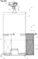
- a first possible embodiment of a conveyor unit 10 according to the invention is shown in Figure 1
- a transport element 40 in the form of a transport bag has a suspension hook 41 which is hooked into a support hook 21 of a conveyor element 20.
- the conveyor element is a carriage of a gravity-fed overhead conveyor system, analogous to the system as used, for example, in the WO 2016/030275 A1 by the applicant.
- the carriage 20 is shown on a guide rail 86 of a conveyor system, where it moves in an intended conveying direction 82.
- the transport bag comprises a front wall 44, a base section 45 and a rear wall 42, which are pivotally connected at the adjoining edges.
- the front wall, rear wall and curved section are designed to be stable and can be made from a suitable plastic material, for example a hollow chamber panel.
- Flexible side walls 46 connect the front wall, rear wall and base section, resulting in a bag 47 with an opening into which at least one piece goods unit 70 can be loaded.
- the side walls are made from a fine-mesh net. It is also possible to use a flexible textile material.
- the side walls 46 are designed in such a way that they can also be folded when the transport bag is folded up, as described below.
- a pivotally mounted spacer 50 in the form of a wire bracket is arranged on each side.
- the spacers 50 are arranged essentially parallel to the base section 45 and are the same length as the base section, and the front wall 44 is essentially parallel to the rear wall 42, so that the rear wall 42, spacer 50, front wall 44 and base section 45 form a parallelogram.
- the weight of the front wall and base section causes the front wall to sink downwards, so that the transport bag changes to a second state in which the front wall and rear wall are close to one another.
- the transport bag can be stored in a conveyor system to save space by lining up the conveyor units flush one behind the other on a guide rail.
- the transport bag By lifting the front wall 44 and/or the bottom section 45 relative to the rear wall 42, the transport bag can be transferred from the second, folded state to a first, unfolded state, as shown in Figure 1 is shown.
- the upward opening of the pocket 47 of the transport bag 40 now has the maximum size.
- a piece goods unit is arranged in the pocket 47 of the transport bag 40, schematically represented by a cuboid-shaped object 70.
- the support hook 21 is attached to a lower end of the carriage 20 facing away from the guide rail 86. It can be made of metal or of a suitable polymer material, for example a glass fiber reinforced thermoplastic material.
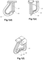
- the support hook 21 has a bracket that is closed when assembled and has two bearing segments 22, 23. When the carriage is in a horizontal position, the first bearing segment 22 corresponds to the lowest point of the bracket of the support hook.
- the suspension hook 41 is in a first stable position, in which the suspension hook is supported at a minimum of potential energy in the first support segment 22. In this stable position, the suspension hook 41 is aligned in a plane transverse to the conveying direction 82, and a front side 48 of the pocket of the transport bag faces in the conveying direction 82.
- the term "transverse” is to be understood as any orientation of the suspension hook plane in which the suspension hook is not in a plane essentially parallel to the conveying direction 82.
- the suspension hook like the rear wall 42, is in a plane perpendicular to the conveying direction 82.
- other angles would also be possible, at which transport bags, whether empty or filled, can be stored one behind the other on the guide rail in a space-saving manner.
- the suspension hook In the second stable position, the suspension hook is aligned in a plane essentially parallel to the conveying direction.
- the term «essentially parallel» is to be understood in such a way that if the suspension hook, and thus also the rear wall of the transport bag, is aligned accordingly, the opening of the bag for filling from the side, i.e. across to the conveying direction, is easily accessible.
- the second stable position corresponds to an alignment of the suspension hook plane parallel to the conveying direction 82.
- an alignment at an angle of 30° to 45° to the conveying direction 82 would also be possible.
- a conveyor unit 10 according to the invention with an alternative embodiment of a transport element 40a is shown in Figure 1A
- the transport element 40a essentially corresponds to the transport bag from Figure 1 , without guide rollers.
- a second hook 58 is arranged in the middle, to which a further transport element can be attached.
- a coat hanger 240 is hung with the hook 241 on the second hook 58 of the transport bag 40a.
- Such a transport bag has the advantage that not only piece goods 70 can be transported and/or stored with the transport bag, but additionally or alternatively also items of clothing on coat hangers. Accordingly, only one transport system is required both for piece goods that can be placed in the bag 47 and for goods that usually have to be stored hanging, for example items of clothing on coat hangers.
- the second hook can be attached to a lower end of the support section as in the example shown, or further up.
- a hook 58' can be attached to the upper end of the support section as in Figure 1A shown in dashed lines. Two or more hooks can also be attached.
- FIG. 1B Another advantageous embodiment of a transport element 40b in the form of a transport bag, as can be used in a conveyor unit according to the invention, is described in Figure 1B shown schematically. This can be assembled with a carriage and support hook, as discussed elsewhere in this description, to form a conveyor element according to the invention.
- the transport bag transport element 40b comprises a front wall 44, a bottom section 45' and a rear wall 42.
- the front wall 44 is connected to the rear wall at its lower end and at its upper end by upper spacer elements 50 and lower spacer elements 51, wherein the spacer elements in the front wall and the rear wall are pivotably mounted.
- the spacer elements 50, 51 are implemented as wire brackets in the embodiment shown.
- Front wall 48 and rear wall 42 are designed to be stable and can be made of a suitable plastic material, for example a stable and at the same time lightweight hollow chamber plate. Unlike the embodiment in Figure 1
- the bottom section is made of a flexible material, for example a tear-resistant plastic film.
- the mechanically stable connection at the lower end of the front wall and rear wall is achieved by the lower spacer elements 51.
- the spacer elements 50, 51 are arranged substantially parallel to one another and of approximately equal length, and the front wall 44 is substantially parallel to the rear wall 42, so that an edge of the rear wall 42, the adjoining spacer 50, the corresponding edge of the front wall 44 and the spacer 51 form a parallelogram.
- the weight of the front wall and base section causes the front wall to sink downwards, so that the transport bag changes to a second state in which the front wall and rear wall are close to one another.
- Flexibly designed side walls 46 connect the front wall 44, rear wall 42, bottom section 45' and the upper spacer element 50 of the corresponding side, resulting in a bag 47 with an opening that can be loaded with at least one piece goods unit 70.
- the side walls are made of a fine-mesh net. It is also possible to use a flexible textile material.
- the side walls 46 are designed in such a way that they can also be folded when the transport bag is folded up.
- the transport bag By lifting the front wall 44 relative to the rear wall 42, the transport bag can be moved from the second, folded state as in Figure 1B(b) shown in a first, unfolded state, as in Figure 1B(a) shown.
- the upward opening of the pocket 47 of the transport bag 40 now has the maximum size.
- stop brackets 52 are provided on both sides, which extend outwards in a lateral direction. These stops 52 ensure that when the front wall 44 is raised relative to the rear wall 42 to open the pocket 47, the lower spacer elements 51 are positioned horizontally towards the front wall as intended. pivot. On the one hand, the stop brackets 52 prevent the spacer elements 51 from pivoting in the opposite direction. On the other hand, they are arranged closer to the front wall than the pivot axis of the spacer elements 51 on the rear wall, so that in the second, folded state of the bag, the spacer elements 51 do not hang completely vertically, but are already slightly inclined towards the front wall, so that a force acting from below on the lower edge of the front wall reliably leads to the bag opening.
- the rear wall 42 is extended at its upper end into a support section 43, at the upper end of which the hanging hook 41 in the form of a wire bracket is pivotally connected to the rear wall 42 or its support section 43.
- the bracket of the hanging hook 41 defines an orientation plane of the hanging hook, and thus of the entire transport bag.
- the wire bracket of the suspension hook 41 is part of a stable wire rod that extends from the wire bracket 41 on both sides along the upper edge of the support section 43, the side edges of the support section 43 and the adjoining side edges of the rear wall 42 to the lower end of the rear wall.
- the wire rod forms the stop brackets 51 there and extends further over part of the lower edge of the rear wall.
- the wire rod is connected to the structure of the rear wall and the support section, thus increasing their mechanical stability.
- FIG. 2 A second possible embodiment of a conveyor unit 10 according to the invention is shown in Figure 2
- Carriage conveyor element 20 and transport bag 40 with suspension hook 41 correspond to the embodiment in Figure 1 , and have already been discussed there.
- the support hook 21 has two bearing segments 22, 23, both of which correspond to a local minimum 65, 65' of the potential energy of a suspension hook 41 suspended in the support hook 21.
- the suspension hook 41 is located on the first bearing segment 22 and takes up a first stable position in the corresponding local minimum 65 of the potential energy.
- the suspension hook 41 and thus the rear wall of the transport bag 40 occupies a plane transverse to the running direction 82 of the carriage 20.
- the suspension hook 41 is located on the second bearing segment 23 and assumes a second stable position at this local minimum 65' of potential energy, in which it is aligned in a plane substantially parallel to the direction of travel 82.
- the suspension hook In order to move back and forth between the first stable position and the second stable position, the suspension hook must overcome an intermediate raised region 25 of the bracket of the support hook 21.
- the suspension hook can be moved back and forth between the two stable positions by rotating the suspension hook or the transport bag around the longitudinal axis.
- the suspension hook thereby overcomes the separating area 25 between the two storage segments 22, 23.
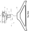
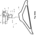
- FIG 2A shows a further embodiment of a conveyor unit 10 according to the invention.
- the carriage conveyor element 20 and the support hook 21 correspond to the embodiment in Figure 2 , and have already been discussed there.
- the transport element 40 is a clothes hanger element in the form of a hanging clothes hanger 240 with hanging hook 241. During operation, an item of clothing is hung on the clothes hanger, but this is not shown for the sake of clarity.
- the suspension hook 241 of the coat hanger 240 can assume two stable positions 61, 61' in the support hook 21.
- a first stable position 61 as in Figure 2A(a) shown, the suspension hook 241 rests on a first bearing segment 22 of the support hook 21.
- the plane of the coat hanger element 241 is essentially transverse to the conveying direction 82.
- a second stable position 62 as in Figure 2A(b) As shown, the suspension hook 241 rests on a second bearing segment 23 of the support hook 21.
- the plane of the coat hanger element 241 is substantially parallel to the conveying direction 82.
- Aligning the ironing plane transverse to the conveying direction allows space-saving conveying and storage of the loaded conveyor units. Aligning it parallel to the conveying direction, on the other hand, allows, among other things, a view of the front and back of the transported garment, for example for a visual inspection of a returned garment.
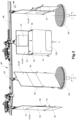
- FIG. 3 A possible embodiment of a conveyor system according to the invention is shown in Figure 3 shown, with an arrangement for loading transport bags.
- the conveyor units 10 essentially correspond to those from Figure 1 , wherein the carriages 20 are shown schematically in a simplified manner.
- a transport bag 40 is fed from the left via a slightly inclined section of the guide rail 86 by gravity.
- the suspension hook is in the first stable position and is aligned together with the rear wall of the transport bag 40 transversely to the conveying direction 82.
- the still empty transport bag 40 is in the second, folded-up state, in which the front wall 44 and base section 45 hang vertically on the spacer elements 50 and the bag has a minimal thickness.
- a bag 40' is now conveyed to the right by appropriate external drive means (not shown) to a first operating arrangement 90 for actively rotating the transport bag.
- the active arrangement 90 is designed as a brush arrangement, namely as a brush turntable that can be raised and lowered vertically.
- the transport bag still in the first stable position, is above the turntable, the turntable is raised and contacts the lowest part of the bag, namely the connecting edge between the front wall and the base section.
- the brush turntable 90 now rotates 90° clockwise, dragging the transport bag 40' with it, which rotates accordingly around the axis of the support hook.
- the suspension hook moves from the first stable position to the second stable position, in which the suspension hook is parallel to the conveying direction 82.
- the brush turntable 90 lowers again and the transport bag 40' remains in the second stable position.
- the rotation by the active arrangement does not necessarily have to take place over the entire angle of rotation. It is sufficient if the suspension hook is rotated so far that it overcomes the elevation of the bracket of the support hook between the two bearing segments. The suspension hook then automatically moves into the second stable position and orientation through gravity.
- the transport bag 40" is now conveyed further to the right, to an opening means 100 for transferring the transport bag into an open state.
- the opening means is designed as a lifting table 100, which lifts the front wall 44 of the transport bag 40", and thus transfers the transport bag into the first state.
- the opening of the pocket 47 of the transport bag is now open at the top.
- a piece goods unit 70 can now be introduced into the pocket 47, as shown schematically in the figure.
- the piece goods unit 70 can be introduced by manual or automated insertion or insertion, for example via a chute, a conveyor belt or a robot arm.
- the lifting table 100 is then lowered again. Since the bag 47 is no longer empty, the transport bag cannot return from the first state to the second state and remains in a filled intermediate state.
- a clothes hanger transport element 40 loaded with a piece of clothing 75 is fed by gravity via a slightly inclined section of the guide rail 86.
- the suspension hook 241 is in the first stable position and the plane of the clothes hanger 241 is aligned transversely to the conveying direction 82.
- a clothes hanger transport element is now conveyed further to the right with appropriate external drive means (not shown) to a first active arrangement 90 for actively rotating the clothes hanger.
- the active arrangement 90 which is only shown schematically, can be designed, for example, as a brush arrangement which, by applying gentle radial force, brings the clothes hanger transport element 40' in relation to the support hook in a counterclockwise direction into the second stable position.
- the suspension hook 241 moves from the first stable position into the second stable position in which the suspension hook and the plane of the clothes hanger are parallel to the conveying direction 82.
- the clothes hanger transport element 40' is now conveyed further to the right, where a camera 95 records the front of the transported article of clothing 75. At the same time, another camera (not shown) can record the back of the article of clothing. These images can then be used to check, for example, the type of article of clothing and its condition (for example in the case of returns in mail order). Such a visual inspection can also be carried out with the human eye instead of with electronic means.
- the clothes hanger transport element 40" is conveyed further to the right, with the hanging hook still in the second stable position. With a further operating arrangement (not shown), the clothes hanger transport element 40" is rotated clockwise back to the first stable position. The hanging hook and the clothes hanger transport element are now again transverse to the conveying direction 82. The clothes hanger transport element is conveyed further to the right and transported further in accordance with its further purpose in the conveyor system 80.
- FIG. 4 Another possible embodiment of a conveyor system 80 according to the invention is shown in Figure 4 schematically executed.
- a plurality of conveyor units with still empty transport pockets 40' in the folded-up second state are provided in a feed area in a shingled arrangement in a space-saving manner.
- the pockets can be brought into the shingled arrangement and held in this arrangement, for example, by appropriate guide means 102.
- the suspension hooks and the transport pockets are already rotated relative to the first stable position transverse to the conveying direction 82. If the foremost transport pocket of the scaled arrangement is now conveyed further to the right, in the embodiment shown a bracket 103 presses this pocket further clockwise around the vertical, so that the suspension hook now automatically moves into the second stable position parallel to the conveying direction 82.
- the pocket 40" can now be returned to the first state using a suitable opening means 100.
- transport bag 40′′′ After the transport bag 40′′′ has been loaded, it is transferred back into the first stable position using suitable means (not shown) and fed into the conveyor system 80 for further use.
- the rotation of the supplied empty transport bags is carried out by means of guide rollers 54. While a transport bag is fed in the first stable position transverse to the conveying direction 82, one or both of the bag's guide rollers 54 slide into a guide roller or guide rail. By suitably arranging the guide rail, the transport bag is rotated about the axis of the carrying hook as it is conveyed further along the conveyor path and reaches the second stable position. The guide rollers are now no longer necessary. After the transport bag has been opened and filled, it can be swiveled from the second stable position to the first stable position in a similar manner.
- This variant has the special advantage that a transport bag does not have to be stopped to rotate between the first and second stable positions, which reduces the cycle time.
- the opening means can also be designed as a ramp which is arranged such that the bottom portion of an empty bag is continuously raised during conveyance from the ramp so that the bag changes into the first, open state.
- Another possibility is to use a ramp-shaped conveyor belt, which runs analogously to the ramp mentioned above, but has the advantage that the transport bag is actively moved at its lower end, so that the opening of the bag can be very controlled.
- Conveyor element 20 and transport bag 40 with suspension hook 41 again correspond to the embodiment in Figure 1 , and have already been discussed there accordingly.
- the support hook 21 of the conveyor unit 10 is designed in such a way that in two specific positions of the support hook 21 in space, a storage segment corresponds to a minimum of the potential energy of the suspension hook 41 in the support hook 21, i.e. a stable position of the suspension hook.
- the first stable position is in Figure 5 not shown. It essentially corresponds to the situation in Figure 2(a) , in which the carriage 20 is arranged horizontally on the guide rail 86 and the support hook 21 is aligned substantially vertically downwards.
- the suspension hook 41 is located in the first stable position in the local minimum 65 of the potential energy, on the first bearing segment 22.
- the suspension hook 41 is aligned in a plane transverse to the conveying direction 82.
- This design of a conveyor unit has the particular advantage that the rotation of the suspension hook can be integrated directly into the conveying process without a conveyor unit having to be stopped or slowed down to rotate the suspension hook and the transport bag. Accordingly, short cycle times are possible.
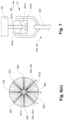
- the support hook 21 is designed in such a way that in a first specific position of the support hook 21 in space (cf. vertical 5) a bearing segment 22 corresponds to a local minimum of the potential energy of the suspension hook 41 in the support hook 21, i.e. a stable position of the suspension hook.
- This first position is in Figure 5A(a) visible, and is analogous to the alignment, for example, in Figure 1(a)
- the suspension hook 41 is in the only stable position, with the transport element aligned transversely to the conveying direction.
- the support hook In a second specific position of the support hook 21 in space, as in Figure 5A(b) shown, which corresponds to a rotation of 45° relative to the vertical 5, the support hook has two bearing segments 22, 23, which correspond to a local minimum of the potential energy of the suspension hook in the support hook, i.e. two possible stable positions of the suspension hook.
- the first bearing segment 22 corresponds to the only bearing segment 22 in the first specific position of the support hook in space, in which the transport element is transverse to the conveying direction. In the second bearing segment 23, the transport element is aligned parallel to the conveying direction.
- the suspension hook 41 in the support hook 21 initially remains in the same stable position on the bearing segment 22 (shown in dashed lines). However, by rotating the transport element, for example by a tangential force acting on the transport element, the suspension hook 41 in the support hook 21 can now be brought from this first stable position 22 to the second stable position 23, as in Figure 5A(b) shown), and also back to the first stable position 22, each time overcoming a local maximum 25 of the potential energy.
- Such a conveyor unit has the advantage that in a first orientation of the support hook, which corresponds to the standard orientation of the guide rail, only a defined orientation of the transport element is possible. If the option of reversible switching between two orientations of the transport element is to be activated, the guide rail is arranged rotated by 45° in a corresponding section of the conveyor path.
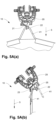
- FIG. 6 A fourth possible embodiment of a conveyor unit 10 according to the invention with a transport pocket 340 as transport element 40 is shown in Figure 6 in a detailed view.
- the conveyor carriage 20 is shown only schematically.
- the transport bag 340 only the suspension hook 341a, 341b and the upper end of the support section 343 are visible.
- the transport bag 340 otherwise corresponds to the transport bags from the Figures 1 and 1A .
- the support hook consists of a first support hook element 321a and a second support hook element in the form of a bolt 321b, which connects the first support hook element 321a to the carriage 20 in a rotationally secure manner.
- the first support hook element 321 consists of a cylinder aligned with the bolt 321b.
- the end face of the cylinder facing the carriage 20 is advantageously designed as a corrugated bearing surface 326. This has radially evenly spaced, radially symmetrical depressions 324 and elevations 325. In the embodiment shown, the angle between two depressions is 90°.
- the suspension hook of the transport bag consists of two elements 341a, 341b.
- a lower bow-shaped, second element 341b is connected to the carrying section 343 of the transport bag.
- the bow-shaped, second carrying hook element 341b is connected to a first carrying hook element 341a.
- the bow 341b can be connected to the first carrying hook element 341a so that it can pivot about a horizontal axis, or it can be secured against rotation.
- the first carrying hook element 341a is designed analogously to the first carrying hook element 321a, with a corrugated bearing surface facing the carrying section with four depressions and four elevations that are flush with the corrugated bearing surface of the first support hook element 341a. In the center of the first support hook element 341a there is a through hole through which the bolt 321b runs.
- the angle between the first stable position and the second stable position of the suspension hook 341a on the support hook 321a is given by the angle between two adjacent elevations 325.
- the angle is accordingly 90°.
- other angles can also be realized, for example 30°, 45° or 120°, as long as an integer multiple of this results in 360°.
- the first support hook element 321a and the first suspension hook element 341a can be manufactured cost-effectively by injection molding from a suitable plastic material, for example from HDPE.
- FIG. 7 A fifth possible embodiment of a conveyor unit 10 according to the invention is shown in Figure 7
- the support hook 321a, 321b corresponds to that of Figure 6 , as is the first hanging hook element 441a.
- the second hanging hook element 441b is designed as a closed bracket.
- a hook 243 of a coat hanger 240 is in turn hooked into this bracket.
- a seventh possible embodiment of a conveyor unit 10 according to the invention is shown in Figure 8 shown.
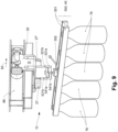
- the transport element is designed in this embodiment as a holding device 550 for a plurality of containers 76.
- the holding device 550 which is only shown schematically, holds five containers 76 arranged in a row in a form-fitting and/or force-fitting manner with two parallel holding elements 551.
- the containers can be released or reversibly fixed by means of a schematically shown actuating element 552.
- the actuating element can be actuated by integrated or external actuator devices or manually.
- the carrying hook essentially corresponds to the carrying hook as it is in Figure 8
- the support hook comprises two support hook elements 521a, 521b, of which a first support hook element 521a comprises a corrugated bearing surface, and is connected to the carriage 20 by two rods of the second support hook element 521b.
- the suspension hook of the transport element 40 consists of two suspension hook elements 541a, 541b, of which a first suspension hook element 541a comprises a corrugated bearing surface.
- the second suspension hook element in the form of a rod or bolt 541b runs through a bore of the first support hook element 521a and connects the first suspension hook element 541a to the holding device 550 for containers.
- shock absorber elements 27, 27' which are mounted on both sides of the carriage 20 in alignment with the guide rail 86, ensure a minimum distance between individual conveyor units 10 in this configuration and serve as shock absorbers between the conveyor units.
- the shock absorber elements can be designed, for example, as blocks made of a suitable elastomer.
- the suspension hook is in a second stable position in which the holding device 550 is essentially parallel to the conveying direction 86.
- the containers of the holding device are therefore also aligned and parallel to the conveying direction 86.
- containers conveyed by another conveyor such as the aforementioned belt conveyor, can also be taken over by an empty conveyor unit in the second configuration.
- the conveyor unit 10 according to the invention offers the advantage that this transfer between the conveyor units 10 according to the invention can be carried out continuously.
- the conveyor units on their conveyor path and the other conveyor must be guided parallel to one another at the same speed and in a suitable alignment with one another during the transfer.
- the holding device is advantageously also actuated during the conveying.
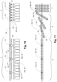
- the spacer elements 28, 28' protrude beyond the holding device to such an extent that in a stacked, staggered arrangement of the conveyor units in the second configuration, as shown in section A of the conveyor path, containers 76 or holding devices 550 of adjacent conveyor units cannot touch each other.
- the shock absorber elements 27, 27' of the carriages have no function since they cannot touch each other.
- FIG 11 the transition between the first configuration of the conveyor units in section C and the second configuration of the conveyor units in section A is shown schematically. If the conveyor units are transported from left to right, the holding device mounted on the suspension hook rotates around the axis of rotation in section B, overcoming the unstable intermediate state as in connection with Figure 6 explained. Then click The suspension hook is rotated by 90° in the new stable position. To trigger the rotation, the holding device or the spacer elements can be triggered by a suitable actuator device.
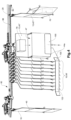
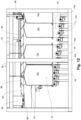
- the secondary drive belt 108b drives the upper roller element 105 via an upper bevel gear 107a, and this in turn drives the lower roller element 106 via a lower bevel gear 107b.
- the gear ratios of the components are selected such that all rollers of all conveyor and lifting units have the same rotational speed and the same direction of rotation.
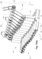
- the front wall moves away from the rear wall in the direction of the upper roller elements 105 due to the operative connection 50, 51 with the rear wall 42.
- the bag opening of the transport bag opens continuously up to a certain, desired point.
Landscapes
- Engineering & Computer Science (AREA)
- Mechanical Engineering (AREA)
- Chain Conveyers (AREA)
Claims (16)
- Unité de transport (10) pour le transport suspendu d'éléments de transport (40, 240, 340, 540, 550) dans un système de transport (80), en particulier un système de transport guidé par rail ou un système de chaîne de transport,avec un élément mouvant (20) avec une direction de transport (82), en particulier un chariot ou un maillon de chaîne de transport, un crochet porteur (21, 321a, 521a) monté sur l'élément mouvant (20), un élément de transport (40, 240, 340, 540, 550), et un crochet de suspension (41, 241, 341a, 441a, 541a) monté sur l'élément de transport, le crochet de suspension étant reposé de manière suspendue dans le crochet porteur ;dans laquelle le crochet porteur (21, 321a, 541a) est conçu de telle sorte que le crochet de suspension (41, 241, 341a, 441a, 541a) puisse prendre au moins deux positions stables (61, 62) dans le crochet porteur (21, 321a, 541a), le crochet de suspension dans une première position stable (61) étant tourné d'un angle par rapport au crochet de suspension dans une deuxième position stable (62) ;dans laquelle le crochet porteur (21, 321a, 521a) présente un premier segment de palier (22) sur lequel, dans une première orientation spatiale déterminée du crochet porteur, le crochet de suspension est reposable dans la première position stable (61) dans laquelle le crochet de suspension est aligné dans un premier plan ; etdans laquelle le crochet porteur (21, 321a, 521a) présente un deuxième segment de palier (23) sur lequel, dans une deuxième orientation spatiale déterminée du crochet porteur qui est identique ou différente de la première orientation spatiale, le crochet de suspension est reposable dans la deuxième position stable (62) dans laquelle le crochet de suspension est aligné dans un deuxième plan ;dans laquelle le crochet de suspension est transférable réciproquement entre la première position (61) et la deuxième position (62) ; etcaractérisée en ce quele premier plan, dans lequel le crochet de suspension (41, 241, 341a, 441a, 541a) s'aligne dans la première position stable (61), est substantiellement transversal à la direction de transport (82) ; et le deuxième plan, dans lequel le crochet de suspension s'aligne dans la deuxième position stable (62), est substantiellement parallèle à la direction de transport.
- Unité de transport selon la revendication 1, dans laquelle le crochet de suspension (41, 241, 341a, 441a, 541a) est transférable réciproquement entre la première position stable (61) et la deuxième position stable (62) de telle sorte que le crochet de suspension repose constamment sur le crochet porteur (21, 321a, 521a).
- Unité de transport selon la revendication 1 ou 2, dans laquelle le crochet de suspension (41, 241, 341a, 441a, 541a b) repose sur le premier segment de palier dans la première position stable (61) et repose sur le deuxième segment de palier dans la deuxième position stable (62) ; et dans laquelle un segment de liaison est disposé entre le premier segment de palier et le deuxième segment de palier, sur lequel le crochet de suspension est transférable de manière coulissante réciproquement entre la première position stable et la deuxième position stable.
- Unité de transport selon l'une quelconque des revendications 1 à 3, dans laquelle, dans une orientation spatiale déterminée du crochet porteur (21, 321a, 521a), le crochet de suspension (41, 241, 341a, 441a, 541a) est reposable sur le premier segment de palier (22) dans une première position stable (61) dans laquelle le crochet de suspension s'aligne dans le premier plan ; et dans la même orientation spatiale du crochet porteur, le crochet de suspension est reposable sur le deuxième segment de palier (23) dans une deuxième position stable (62) dans laquelle le crochet de suspension s'aligne dans le deuxième plan, la première position (61) et la deuxième position (62) correspondant à des minima locaux (65) de l'énergie potentielle de l'élément de transport (40, 240, 340, 540, 550) reposé de manière suspendue ; et dans lequel le crochet de suspension est transférable réciproquement entre la première position stable (61) et la deuxième position stable (62) en faisant tourner le crochet de suspension d'un angle de rotation déterminé autour de la perpendiculaire.
- Unité de transport selon l'une quelconque des revendications 1 à 3, dans laquelle, dans une première orientation spatiale déterminée du crochet porteur (21), le crochet de suspension (41) est reposable sur le premier segment de palier (22) dans une première position stable (61) dans laquelle le crochet de suspension s'aligne dans le premier plan ; et dans une deuxième orientation spatiale différente de la première orientation spatiale déterminée du crochet porteur, le crochet de suspension est reposable sur le deuxième segment de palier (23) dans une deuxième position stable (62) dans laquelle le crochet de suspension s'aligne dans le deuxième plan, dans laquelle, dans la première orientation spatiale déterminée du crochet porteur, la première position (61) correspond à un minimum (65) de l'énergie potentielle de l'élément de transport suspendu et la deuxième position (62) ne correspond à aucun minimum de l'énergie potentielle ; dans la deuxième orientation spatiale déterminée du crochet porteur, la deuxième position (62) correspond à un minimum (65') de l'énergie potentielle de l'élément de transport suspendu et la première position (61) ne correspond à aucun minimum de l'énergie potentielle ; et le crochet porteur est transférable réciproquement entre la première orientation spatiale déterminée du crochet porteur et la deuxième orientation spatiale déterminée du crochet porteur en tournant d'un angle de rotation déterminé, de sorte que le crochet de suspension est transférable réciproquement par gravité entre la première position (61) et la deuxième position (62).
- Unité de transport selon la revendication 5, dans laquelle le crochet de suspension (41) est transférable réciproquement entre la première position (61) et la deuxième position (62) en faisant tourner l'élément mouvant (20) autour la direction de transport (82).
- Unité de transport selon l'une quelconque des revendications 1 à 3, dans laquelle, dans une première orientation spatiale déterminée du crochet porteur (21, 321a, 521a), le crochet de suspension (41, 241, 341a, 441a, 541a) est reposable sur le premier segment de palier (22) dans une première position stable (61) dans laquelle le crochet de suspension s'aligne dans le premier plan ; et dans une deuxième orientation spatiale différente de la première orientation spatiale déterminée du crochet porteur, le crochet de suspension est reposable à la fois sur le premier segment de palier (22) dans la première position stable (61), dans laquelle le crochet de suspension s'aligne au premier plan, ainsi que sur le deuxième segment de palier (23) dans une deuxième position stable (62) dans laquelle le crochet de suspension s'aligne au deuxième plan ; dans laquelle, dans la première orientation spatiale déterminée du crochet porteur, la première position (61) correspond à un minimum (65) de l'énergie potentielle de l'élément de transport suspendu, et dans laquelle, dans la deuxième orientation spatiale, la première position (61) et la deuxième position (62) correspondent à des minima locaux (65) de l'énergie potentielle de l'élément de transport suspendu (40) ; et dans laquelle, dans la deuxième orientation spatiale du crochet porteur le crochet de suspension est transférable réciproquement entre la première position stable (61) et la deuxième position stable (62) en tournant le crochet de suspension d'un angle de rotation déterminé autour de la perpendiculaire.
- Système de transport (80) pour le transport suspendu guidé d'éléments de transport (40, 240, 340, 540, 550), en particulier de sacs de transport et/ou de cintres, le long d'une voie de transport, en particulier un système de transport guidé par rail ou un système de chaîne de transport, avec au moins une unité de transport (10) selon l'une des revendications 1 à 7.
- Système de transport selon la revendication 8, dans lequel le premier plan dans lequel le crochet de suspension (41, 241, 341a, 441a, 541a) s'aligne dans la première position stable (61) est substantiellement transversal à la direction de transport (82) ; et le deuxième plan dans lequel le crochet de suspension s'aligne dans la deuxième position stable (62) est substantiellement parallèle à la direction de transport.
- Système de transport selon la revendication 8 ou 9, dans lequel un agencement actif (90) est prévu, avec lequel les éléments de transport (40, 240, 340, 540, 550) peuvent être tournés d'un angle de rotation déterminé à un endroit déterminé de la voie de transport, de sorte que le crochet de suspension (41, 241, 341a, 441a, 541a) est transféré de la première position (61) à la deuxième position (62) ou de la deuxième position à la première position.
- Système de transport selon la revendication 8 ou 9, dans lequel, dans une section déterminée de la voie de transport, le crochet porteur (21, 321a, 521a) de l'unité de transport (10) est aligné de telle sorte que le crochet de suspension (41, 241, 341a, 441a, 541a) de l'élément de transport (40, 240, 340, 540, 550) occupe une première position stable (61), et dans une autre section déterminée, le crochet porteur de l'unité de transport est aligné de telle sorte que le crochet de suspension de l'élément de transport occupe une deuxième position stable (62).
- Système de transport selon l'une quelconque des revendications 8 à 11, dans lequel l'unité de transport (10) est une unité de transport selon la revendication 6 et le crochet de suspension (41) est transférable de la deuxième position (62) à la première position (61) en faisant tourner l'élément mouvant (20) autour de la direction de transport (82), et dans lequel sont prévus des moyens d'ouverture (100, 101) avec lesquels un sac de transport (40, 340) peut être amenée dans le premier état ouvert à un endroit déterminé de la voie de transport, le crochet de suspension (21, 321a) se trouvant dans la deuxième position (62) et la paroi arrière (42, 43) du sac de transport étant orienté substantiellement parallèlement à la direction de transport.
- Système de transport selon la revendication 12, dans lequel un dispositif de levage est prévu comme moyens d'ouverture (100, 101), en particulier une table élévatrice (100) ou un dispositif de rampe (101).
- Système de transport (80) pour le transport suspendu guidé d'éléments de transport (40, 240, 340, 540, 550) le long d'une voie de transport, en particulier un système de transport guidé par rails ou un système de chaîne de transport, qui est conçu de telle sorte qu'une pluralité d'éléments de transport peut être mis à disposition sur une section déterminée de la voie de transport dans une disposition à chevauchement, le système de transport (80) contenant au moins une unité de transport (10) selon l'une quelconque des revendications 1 à 7.
- Procédé d'introduction de marchandises diverses (70) dans des éléments de transport (40, 340) d'un système de transport (80), comprenant les étapes suivantes :- mettre à disposition un système de transport (80) selon lune des revendications 8 à 13 ;- alimenter une unité de transport (10) du système de transport le long de la voie de transport, le crochet de suspension (41, 341a) de l'élément de transport (40, 340) se trouvant dans la première position stable (61) ;- transférer le crochet de suspension de l'élément de transport de ladite unité de transport de la première position stable à la deuxième position stable (62) ;- introduire au moins une unité de marchandises à la pièce (70) dans l'élément de transport réceptif de ladite unité de transport ; et- transférer le crochet de suspension dudit élément de transport de la deuxième position stable à la première position stable.
- Procédé d'inspection visuelle de vêtements (75) suspendus sur des éléments de transport de cintres (40, 240, 540) d'un système de transport (80) ou de récipients (76) maintenus dans des dispositifs de maintien de récipients (40, 550) d'un système de transport, comprenant les étapes suivantes :- mettre à disposition un système de transport (80) selon l'une des revendications 8 à 13 ;- alimenter une unité de transport (10) du système de transport le long de la voie de transport, le crochet de suspension (41, 241, 541a) de l'élément de transport du cintre (40, 240, 540) ou de l'élément de transport du dispositif de maintien de récipients (40, 550) se trouvant dans la première position stable (61) ;- transférer le crochet de suspension de l'élément de transport du cintre ou de l'élément de transport du dispositif de maintien de récipients de ladite unité de transport de la première position stable à la deuxième position stable (62) ;- inspecter (95) visuellement de l'avant et/ou de l'arrière d'un vêtement (75) suspendu sur l'élément de transport du cintre ou d'un récipient (76) maintenu dans le dispositif de maintien de récipients de l'élément de transport ; et- transférer le crochet de suspension de l'élément de transport du cintre ou de l'élément de transport du dispositif de maintien de récipients de la deuxième position stable à la première position stable.
Applications Claiming Priority (3)
| Application Number | Priority Date | Filing Date | Title |
|---|---|---|---|
| CH00110/17A CH713399A1 (de) | 2017-01-31 | 2017-01-31 | Fördereinheit zum hängenden Transport von Transportelementen in zwei Positionen. |
| CH00796/17A CH713405A2 (de) | 2017-01-31 | 2017-06-20 | Vorrichtung und Verfahren zum Drehen, Öffnen und Befüllen hängend geförderter Transporttaschen. |
| PCT/IB2018/050445 WO2018142242A1 (fr) | 2017-01-31 | 2018-01-25 | Dispositif et procédé pour faire tourner, ouvrir et remplir des sacs de transport qui sont transportés suspendus |
Publications (2)
| Publication Number | Publication Date |
|---|---|
| EP3577041A1 EP3577041A1 (fr) | 2019-12-11 |
| EP3577041B1 true EP3577041B1 (fr) | 2024-07-10 |
Family
ID=62974852
Family Applications (1)
| Application Number | Title | Priority Date | Filing Date |
|---|---|---|---|
| EP18702823.8A Active EP3577041B1 (fr) | 2017-01-31 | 2018-01-25 | Dispositif et procédé pour faire tourner, ouvrir et remplir des sacs de transport qui sont transportés suspendus |
Country Status (4)
| Country | Link |
|---|---|
| US (2) | US11084658B2 (fr) |
| EP (1) | EP3577041B1 (fr) |
| CH (2) | CH713399A1 (fr) |
| WO (1) | WO2018142242A1 (fr) |
Families Citing this family (28)
| Publication number | Priority date | Publication date | Assignee | Title |
|---|---|---|---|---|
| CA3001414A1 (fr) * | 2015-11-25 | 2017-06-01 | Ferag Ag | Sac de transport et procede de remplissage et de vidage d'un tel sac de transport |
| CH713398A1 (de) | 2017-01-31 | 2018-07-31 | Ferag Ag | Vorrichtung zum Entleeren hängend geförderter Transporttaschen. |
| CH713399A1 (de) | 2017-01-31 | 2018-07-31 | Ferag Ag | Fördereinheit zum hängenden Transport von Transportelementen in zwei Positionen. |
| US12637305B2 (en) | 2017-01-31 | 2026-05-26 | Ferag Ag | Device, method and system for commissioning goods |
| US11878876B2 (en) | 2017-01-31 | 2024-01-23 | Ferag Ag | Device for emptying transport bags conveyed in a suspended manner |
| CH715134A1 (de) * | 2018-06-28 | 2019-12-30 | Ferag Ag | Vorrichtung und Verfahren zur Inspektion von hängend förderbaren Transporttaschen. |
| DE102018219583C5 (de) | 2018-11-15 | 2025-09-11 | Dürkopp Fördertechnik GmbH | Förderanlage und Verfahren zum Fördern von Waren |
| CH715719A1 (de) | 2019-01-09 | 2020-07-15 | Ferag Ag | Pufferspeicheranlage für Hängefördersysteme. |
| AT522067B1 (de) | 2019-02-07 | 2020-08-15 | Tgw Mechanics Gmbh | Transportträgersystem und Hängefördervorrichtung mit Transportträgern zum Transport von Hängewaren |
| US10928133B1 (en) * | 2019-06-05 | 2021-02-23 | Pawel Malecki | Air dryer apparatus for garments with conveying mechanism |
| CH716519A1 (de) * | 2019-08-22 | 2021-02-26 | Ferag Ag | Vorrichtung und Verfahren zum Transferieren von Waren-Einheiten in Fördereinheiten und/oder aus Fördereinheiten eines Hängefördersystems. |
| CN110775528B (zh) * | 2019-09-24 | 2020-12-18 | 中国三冶集团有限公司宁波分公司 | 一种链式输送机的安装方法 |
| NL1043789B1 (nl) * | 2020-09-17 | 2022-05-23 | C C Van Der Gaag Holding B V | Aandrijfinrichting voor aan een geleidingsrail opgehangen verticale langwerpige units, zoals kweekunits voor gewassen |
| US12459745B2 (en) | 2021-04-16 | 2025-11-04 | BEUMER Group GmbH & Co. KG | Loading station for an overhead conveyor with transport pouches for conveyed goods |
| DE102021002833A1 (de) * | 2021-06-02 | 2021-08-12 | Paul Janzen | Transporttasche zum hängenden Transport von Fördergut sowie Beladestation und Förderanlage für diese Transporttaschen |
| DE102021003096A1 (de) * | 2021-06-17 | 2021-08-19 | Paul Janzen | Transporttasche zum hängenden Transport von Fördergut sowie eine Entladestation, Schließstation und eine Förderanlage für diese Transporttaschen |
| WO2023095049A1 (fr) | 2021-11-29 | 2023-06-01 | Ferag Ag | Dispositif de gestion du chargement d'unités de transport d'un système d'acheminement |
| US12246872B2 (en) | 2022-05-31 | 2025-03-11 | Ferag Ag | Device and method for loading transport containers |
| EP4310034A3 (fr) | 2022-05-31 | 2024-04-10 | Ferag Ag | Dispositif et procédé de chargement de conteneurs de transport |
| EP4434918A1 (fr) * | 2023-03-23 | 2024-09-25 | Herbert Kannegiesser GmbH | Dispositif pour tourner des articles textiles suspendus à des cintres de transport, en particulier des vêtements |
| CH720733A1 (de) | 2023-04-25 | 2024-10-31 | Ferag Ag | Kommissionieranlage |
| CH720747A1 (de) | 2023-04-28 | 2024-11-15 | Ferag Ag | Kommissionierungsanlage und verfahren zum kommissionieren von stückgütern |
| KR102606552B1 (ko) * | 2023-06-12 | 2023-11-29 | 주식회사 청세 | 세탁물 출고장치 |
| CH721145A1 (de) * | 2023-09-21 | 2025-03-31 | Ferag Ag | Vorrichtung, verfahren und system zum stabilisieren und beladen von transporttaschen |
| CH721462A1 (de) | 2023-12-22 | 2025-06-30 | Ferag Ag | Anlage und Verfahren zum Sortieren und Zwischenspeichern von Stückgütern |
| CN118990594B (zh) * | 2024-10-24 | 2025-01-24 | 中国电器科学研究院股份有限公司 | 一种用于转挂的机器人手臂及夹爪机构 |
| CN119262850B (zh) * | 2024-12-12 | 2025-02-28 | 合肥浩普智能装备科技有限公司 | 一种磁悬浮式倒包输送机 |
| CN120774104B (zh) * | 2025-08-19 | 2026-02-03 | 江西一创新材料有限公司 | 一种电池级碳酸锂智能悬挂输送装置 |
Family Cites Families (47)
| Publication number | Priority date | Publication date | Assignee | Title |
|---|---|---|---|---|
| US2643761A (en) | 1950-03-16 | 1953-06-30 | Campbell Wyant And Cannon Foun | Means for unloading articles from overhead conveyers |
| US2609082A (en) * | 1951-03-12 | 1952-09-02 | John M Leach | Hook conveyer |
| US2992721A (en) | 1958-07-11 | 1961-07-18 | Eger Orville David | Methods and systems for handling and transporting blocks |
| DE1175153B (de) | 1961-10-02 | 1964-07-30 | Heinrich Klein | Entladestelle fuer Transportkuebel von Drahtseilbahnen, Haengebahnen u. dgl. |
| JPS4611228Y1 (fr) | 1967-12-28 | 1971-04-19 | ||
| DE1940256C3 (de) | 1969-08-07 | 1975-11-20 | Gustav Georg Veith Gmbh & Co Kg, 8000 Muenchen | Fördereinrichtung, insbesondere für die innerbetriebliche Hängeförderung in der Bekleidungsindustrie |
| JPS5520654Y2 (fr) * | 1975-09-17 | 1980-05-17 | ||
| JPS5237381A (en) * | 1975-09-17 | 1977-03-23 | Kubota Ltd | Attitude control device |
| CH639043A5 (fr) | 1980-10-21 | 1983-10-31 | Inventio Ag | Installation pour l'enlevement et la reception automatiques de charges par l'intermediaire de vehicules de transport. |
| SU1169904A1 (ru) | 1983-11-21 | 1985-07-30 | Киевское Опытно-Конструкторское Бюро Торгового Машиностроения | Устройство дл съема изделий с захватов подвесного конвейера |
| JPS60176868U (ja) * | 1984-05-01 | 1985-11-22 | 株式会社小松製作所 | ハンガ−ライン |
| DE3605317C1 (en) | 1986-02-19 | 1987-02-26 | Veit Gmbh & Co | Suspended conveying system |
| FR2637274A1 (fr) | 1988-10-04 | 1990-04-06 | Ano Sarl | Trieurs convoyeurs d'objets automatiques |
| DE3917630C2 (de) * | 1989-05-31 | 1993-10-07 | Kannegiesser H Gmbh Co | Vorrichtung zum hängenden Transport von Gegenständen, insbesondere Kleidungsstücken, durch eine Behandlungseinrichtung |
| JPH0749292B2 (ja) | 1991-05-15 | 1995-05-31 | 株式会社フジキカイ | 容器の供給装置 |
| DE19500612C2 (de) * | 1995-01-11 | 1996-12-12 | Duerkopp Adler Ag | Codierbarer Adapter zur Verwendung mit einer Hängeförderanlage |
| DE19504879C2 (de) * | 1995-02-14 | 1996-11-28 | Fraunhofer Ges Forschung | Förderer zum Transport von auf Bügeln hängenden Teilen, insbesondere Kleidungsstücken |
| DK1274640T3 (da) | 2000-04-20 | 2005-12-05 | Ferag Ag | Indretning til transport af genstande |
| US8151973B2 (en) * | 2002-11-01 | 2012-04-10 | Kraft Foods Global Brands Llc | Suspension device for linked products |
| DE10354419A1 (de) * | 2003-11-21 | 2005-06-23 | Wf Logistik Gmbh | Hängefördereinrichtung zum Transportieren von Fördergut, insbesondere Kleidungsstücken |
| US7080727B1 (en) * | 2003-12-02 | 2006-07-25 | Terry Sanderson | Clothing transport and storage system, apparatus and method |
| DE102004018569B4 (de) | 2004-04-16 | 2016-06-09 | Psb Intralogistics Gmbh | Sammeleinrichtung zum Aufnehmen von Objekten beim sortierenden Sammeln der Objekte sowie Fördervorrichtung zum Transport von Sammeltaschen |
| DE502007004045D1 (de) * | 2007-02-16 | 2010-07-15 | Rsl Logistik Gmbh & Co Kg | Fördermittel für eine hängefördereinrichtung |
| DE102008026720A1 (de) | 2008-06-04 | 2009-12-10 | Dürkopp Adler AG | Transport-Tasche und Förder-Anlage für eine Transport-Tasche |
| DE102008061685A1 (de) | 2008-12-11 | 2010-06-17 | Dürkopp Adler AG | Belade-Station für in einer Hänge-Förder-Anlage transportierte Transport-Taschen |
| DE102010033905A1 (de) * | 2010-08-10 | 2012-02-16 | Dürkopp Fördertechnik GmbH | Förderanlage mit Tragetaschen für Fördergut |
| DE102011116081B3 (de) | 2011-10-10 | 2013-04-11 | SSI Schäfer PEEM GmbH | System und Verfahren zum manuellen Batch-Picken unter Anwendung des Ware-zum-Mann-Prinzips |
| DE102012212518B4 (de) | 2012-07-17 | 2023-12-07 | Rsl Logistik Gmbh & Co. Kg | Fördergutbehälter, Hängefördereinrichtung und Verfahren zum Transportieren |
| DE102012018925B4 (de) | 2012-09-18 | 2020-06-18 | Ssi Schäfer Automation Gmbh | Tasche für Hängeförderer, Beladestation, Entladestation und Taschen-Hängeförderanlage |
| DE102014201301A1 (de) * | 2014-01-24 | 2015-07-30 | Dürkopp Fördertechnik GmbH | Fördervorrichtung und Verfahren zum automatisierten Fördern von Einzelwaren |
| DE102014203298A1 (de) | 2014-02-24 | 2015-08-27 | Rsl Logistik Gmbh & Co. Kg | Hängefördereinrichtung mit Ladestation |
| CH710022A1 (de) | 2014-08-27 | 2016-02-29 | Ferag Ag | Laufwagen für ein Fördersystem, insbesondere für einen Schwerkraftförderer, Fördersystem und Verfahren zum Betrieb eines Fördersystems. |
| CH710650A1 (de) | 2015-01-26 | 2016-07-29 | Ferag Ag | Transportvorrichtung, insbesondere in Form eines Hängeförderers. |
| CH710856A1 (de) | 2015-03-02 | 2016-09-15 | Ferag Ag | Transporteinheit einer Hängefördervorrichtung mit einem Pufferelement. |
| CH711565A1 (en) | 2015-09-24 | 2017-03-31 | Ferag Ag | Transport bag for the transport and / or storage of objects and transport device with such a transport bag. |
| CA3001414A1 (fr) | 2015-11-25 | 2017-06-01 | Ferag Ag | Sac de transport et procede de remplissage et de vidage d'un tel sac de transport |
| DE102016208866A1 (de) | 2016-05-23 | 2017-11-23 | Rsl Logistik Gmbh & Co. Kg | Fördergutübergabestation sowie eine damit ausgestattete Hängefördereinrichtung |
| CH712560A1 (de) | 2016-05-31 | 2017-12-15 | Ferag Ag | Laufwagen für ein schienengeführtes Fördersystem sowie Fördersystem mit einem solchen Laufwagen. |
| CH713399A1 (de) | 2017-01-31 | 2018-07-31 | Ferag Ag | Fördereinheit zum hängenden Transport von Transportelementen in zwei Positionen. |
| WO2018078098A1 (fr) | 2016-10-27 | 2018-05-03 | Ferag Ag | Procédé et dispositif pour ouvrir un sac de transport |
| EP3315433B1 (fr) * | 2016-11-01 | 2020-07-15 | Ferag AG | Dispositif de transmission pour support de produits doté des moyens de retenue |
| DE202017100206U1 (de) | 2017-01-16 | 2018-04-17 | Tgw Mechanics Gmbh | Fördergutbehälter mit Auswerfvorrichtung und zugehörige Hängefördervorrichtung |
| CH713387A1 (de) | 2017-01-26 | 2018-07-31 | Ferag Ag | Beschickungsvorrichtung zum kontinuierlichen Beschicken von Aufnahmeeinheiten mit Transportgütern. |
| CH713551A1 (de) | 2017-03-07 | 2018-09-14 | Ferag Ag | Verfahren zum Kommissionieren von Waren und Kommissionierungsanlage zur Durchführung des Verfahrens. |
| AT520412B1 (de) | 2017-08-18 | 2021-01-15 | Knapp Ag | Transporttasche zum Transportieren von Produkten |
| DE202017105508U1 (de) | 2017-09-12 | 2017-11-06 | Psb Intralogistics Gmbh | Transporttasche und Förderanlage umfassend eine Transporttasche |
| ES2938627T3 (es) | 2018-05-29 | 2023-04-13 | Schaefer Systems Int Inc | Sistema basado en grupos y método para cumplimentación de pedidos de comercio electrónico |
-
2017
- 2017-01-31 CH CH00110/17A patent/CH713399A1/de unknown
- 2017-06-20 CH CH00796/17A patent/CH713405A2/de unknown
-
2018
- 2018-01-25 US US16/481,218 patent/US11084658B2/en active Active
- 2018-01-25 WO PCT/IB2018/050445 patent/WO2018142242A1/fr not_active Ceased
- 2018-01-25 EP EP18702823.8A patent/EP3577041B1/fr active Active
-
2021
- 2021-07-16 US US17/378,314 patent/US11753249B2/en active Active
Also Published As
| Publication number | Publication date |
|---|---|
| US20210395017A1 (en) | 2021-12-23 |
| US20190367282A1 (en) | 2019-12-05 |
| EP3577041A1 (fr) | 2019-12-11 |
| US11753249B2 (en) | 2023-09-12 |
| CH713405A2 (de) | 2018-07-31 |
| US11084658B2 (en) | 2021-08-10 |
| WO2018142242A1 (fr) | 2018-08-09 |
| CH713399A1 (de) | 2018-07-31 |
Similar Documents
| Publication | Publication Date | Title |
|---|---|---|
| WO2018142242A1 (fr) | Dispositif et procédé pour faire tourner, ouvrir et remplir des sacs de transport qui sont transportés suspendus | |
| AT521110B1 (de) | Entladestation und Verfahren zum Entladen eines mit einem Fördergut beladenen Fördergutbehälters | |
| EP3782936B1 (fr) | Sac de transport pour un système de transport suspendu | |
| EP3380417B1 (fr) | Dispositif de chargement de sacs de transport | |
| EP4079663B1 (fr) | Dispositif de chargement | |
| EP3577047B1 (fr) | Dispositif de vidage de sacs de transport acheminés suspendus | |
| EP3359471B1 (fr) | Système de stockage automatisé et procédé de stockage d'articles suspendus dans ce système de stockage | |
| EP3110725B1 (fr) | Convoyeur aérien comprenant un poste de chargement | |
| WO2018078098A1 (fr) | Procédé et dispositif pour ouvrir un sac de transport | |
| AT518878B1 (de) | Automatisiertes Lagersystem zum Transport von in Fahrtrichtung gedrehten Ladungsträgern | |
| EP3634887B1 (fr) | Système de stockage automatisé pour articles suspendus et sacs suspendus présentant une meilleure prise ainsi que dispositif de transport d'articles et procédé de fonctionnement pour ceux-ci | |
| EP3532413B1 (fr) | Procédé et dispositif pour ouvrir un sac de transport | |
| EP4003848B1 (fr) | Système de stockage et de prélèvement et procédé pour empiler des marchandises et sécuriser la pile de marchandises avec une bande | |
| DE69313784T2 (de) | Entladeeinheit einer Fördereinrichtung und Verfahren zum Entladen von der Fördereinrichtung | |
| CH713089A1 (de) | Verfahren und Vorrichtung zum Öffnen einer Transporttasche. | |
| DE202011005493U1 (de) | Vertikaler Schachtförderer und -stapler | |
| WO2025062197A1 (fr) | Dispositif, procédé et système de stabilisation et de chargement de poches de transport | |
| AT519961B1 (de) | Automatisiertes Lagersystem für Hängewaren und Hängetaschen mit verbessertem Zugriff sowie Warentransportvorrichtung und Betriebsverfahren dazu | |
| CH721643A1 (de) | Vorrichtung und Verfahren für das Beladen u nd Entladen von Transporteinheiten eines Hängefördersystems | |
| CH721504A2 (de) | Vorrichtung und anlage zum entleeren hängend geförderter transporttaschen | |
| EP4209433A1 (fr) | Transporteur vertical permettant de transporter des marchandises, ainsi que procédé de transport vertical | |
| DE202004000837U1 (de) | Zwischenspeicher | |
| DE2263330B2 (de) | Lagersystem mit durchlaufregalen fuer haengende artikeltraeger |
Legal Events
| Date | Code | Title | Description |
|---|---|---|---|
| STAA | Information on the status of an ep patent application or granted ep patent |
Free format text: STATUS: UNKNOWN |
|
| STAA | Information on the status of an ep patent application or granted ep patent |
Free format text: STATUS: THE INTERNATIONAL PUBLICATION HAS BEEN MADE |
|
| PUAI | Public reference made under article 153(3) epc to a published international application that has entered the european phase |
Free format text: ORIGINAL CODE: 0009012 |
|
| STAA | Information on the status of an ep patent application or granted ep patent |
Free format text: STATUS: REQUEST FOR EXAMINATION WAS MADE |
|
| 17P | Request for examination filed |
Effective date: 20190823 |
|
| AK | Designated contracting states |
Kind code of ref document: A1 Designated state(s): AL AT BE BG CH CY CZ DE DK EE ES FI FR GB GR HR HU IE IS IT LI LT LU LV MC MK MT NL NO PL PT RO RS SE SI SK SM TR |
|
| AX | Request for extension of the european patent |
Extension state: BA ME |
|
| DAV | Request for validation of the european patent (deleted) | ||
| DAX | Request for extension of the european patent (deleted) | ||
| STAA | Information on the status of an ep patent application or granted ep patent |
Free format text: STATUS: EXAMINATION IS IN PROGRESS |
|
| 17Q | First examination report despatched |
Effective date: 20211027 |
|
| P01 | Opt-out of the competence of the unified patent court (upc) registered |
Effective date: 20230309 |
|
| GRAP | Despatch of communication of intention to grant a patent |
Free format text: ORIGINAL CODE: EPIDOSNIGR1 |
|
| STAA | Information on the status of an ep patent application or granted ep patent |
Free format text: STATUS: GRANT OF PATENT IS INTENDED |
|
| INTG | Intention to grant announced |
Effective date: 20240131 |
|
| GRAS | Grant fee paid |
Free format text: ORIGINAL CODE: EPIDOSNIGR3 |
|
| GRAA | (expected) grant |
Free format text: ORIGINAL CODE: 0009210 |
|
| STAA | Information on the status of an ep patent application or granted ep patent |
Free format text: STATUS: THE PATENT HAS BEEN GRANTED |
|
| AK | Designated contracting states |
Kind code of ref document: B1 Designated state(s): AL AT BE BG CH CY CZ DE DK EE ES FI FR GB GR HR HU IE IS IT LI LT LU LV MC MK MT NL NO PL PT RO RS SE SI SK SM TR |
|
| REG | Reference to a national code |
Ref country code: CH Ref legal event code: EP |
|
| REG | Reference to a national code |
Ref country code: DE Ref legal event code: R096 Ref document number: 502018014833 Country of ref document: DE |
|
| REG | Reference to a national code |
Ref country code: NL Ref legal event code: FP |
|
| REG | Reference to a national code |
Ref country code: ES Ref legal event code: FG2A Ref document number: 2985442 Country of ref document: ES Kind code of ref document: T3 Effective date: 20241105 |
|
| REG | Reference to a national code |
Ref country code: LT Ref legal event code: MG9D |
|
| PG25 | Lapsed in a contracting state [announced via postgrant information from national office to epo] |
Ref country code: PT Free format text: LAPSE BECAUSE OF FAILURE TO SUBMIT A TRANSLATION OF THE DESCRIPTION OR TO PAY THE FEE WITHIN THE PRESCRIBED TIME-LIMIT Effective date: 20241111 |
|
| PG25 | Lapsed in a contracting state [announced via postgrant information from national office to epo] |
Ref country code: PT Free format text: LAPSE BECAUSE OF FAILURE TO SUBMIT A TRANSLATION OF THE DESCRIPTION OR TO PAY THE FEE WITHIN THE PRESCRIBED TIME-LIMIT Effective date: 20241111 |
|
| PG25 | Lapsed in a contracting state [announced via postgrant information from national office to epo] |
Ref country code: NO Free format text: LAPSE BECAUSE OF FAILURE TO SUBMIT A TRANSLATION OF THE DESCRIPTION OR TO PAY THE FEE WITHIN THE PRESCRIBED TIME-LIMIT Effective date: 20241010 |
|
| PG25 | Lapsed in a contracting state [announced via postgrant information from national office to epo] |
Ref country code: GR Free format text: LAPSE BECAUSE OF FAILURE TO SUBMIT A TRANSLATION OF THE DESCRIPTION OR TO PAY THE FEE WITHIN THE PRESCRIBED TIME-LIMIT Effective date: 20241011 Ref country code: FI Free format text: LAPSE BECAUSE OF FAILURE TO SUBMIT A TRANSLATION OF THE DESCRIPTION OR TO PAY THE FEE WITHIN THE PRESCRIBED TIME-LIMIT Effective date: 20240710 Ref country code: PL Free format text: LAPSE BECAUSE OF FAILURE TO SUBMIT A TRANSLATION OF THE DESCRIPTION OR TO PAY THE FEE WITHIN THE PRESCRIBED TIME-LIMIT Effective date: 20240710 |
|
| PG25 | Lapsed in a contracting state [announced via postgrant information from national office to epo] |
Ref country code: BG Free format text: LAPSE BECAUSE OF FAILURE TO SUBMIT A TRANSLATION OF THE DESCRIPTION OR TO PAY THE FEE WITHIN THE PRESCRIBED TIME-LIMIT Effective date: 20240710 |
|
| PG25 | Lapsed in a contracting state [announced via postgrant information from national office to epo] |
Ref country code: LV Free format text: LAPSE BECAUSE OF FAILURE TO SUBMIT A TRANSLATION OF THE DESCRIPTION OR TO PAY THE FEE WITHIN THE PRESCRIBED TIME-LIMIT Effective date: 20240710 |
|
| PG25 | Lapsed in a contracting state [announced via postgrant information from national office to epo] |
Ref country code: IS Free format text: LAPSE BECAUSE OF FAILURE TO SUBMIT A TRANSLATION OF THE DESCRIPTION OR TO PAY THE FEE WITHIN THE PRESCRIBED TIME-LIMIT Effective date: 20241110 |
|
| PG25 | Lapsed in a contracting state [announced via postgrant information from national office to epo] |
Ref country code: HR Free format text: LAPSE BECAUSE OF FAILURE TO SUBMIT A TRANSLATION OF THE DESCRIPTION OR TO PAY THE FEE WITHIN THE PRESCRIBED TIME-LIMIT Effective date: 20240710 |
|
| PG25 | Lapsed in a contracting state [announced via postgrant information from national office to epo] |
Ref country code: RS Free format text: LAPSE BECAUSE OF FAILURE TO SUBMIT A TRANSLATION OF THE DESCRIPTION OR TO PAY THE FEE WITHIN THE PRESCRIBED TIME-LIMIT Effective date: 20241010 |
|
| PG25 | Lapsed in a contracting state [announced via postgrant information from national office to epo] |
Ref country code: RS Free format text: LAPSE BECAUSE OF FAILURE TO SUBMIT A TRANSLATION OF THE DESCRIPTION OR TO PAY THE FEE WITHIN THE PRESCRIBED TIME-LIMIT Effective date: 20241010 Ref country code: PL Free format text: LAPSE BECAUSE OF FAILURE TO SUBMIT A TRANSLATION OF THE DESCRIPTION OR TO PAY THE FEE WITHIN THE PRESCRIBED TIME-LIMIT Effective date: 20240710 Ref country code: NO Free format text: LAPSE BECAUSE OF FAILURE TO SUBMIT A TRANSLATION OF THE DESCRIPTION OR TO PAY THE FEE WITHIN THE PRESCRIBED TIME-LIMIT Effective date: 20241010 Ref country code: LV Free format text: LAPSE BECAUSE OF FAILURE TO SUBMIT A TRANSLATION OF THE DESCRIPTION OR TO PAY THE FEE WITHIN THE PRESCRIBED TIME-LIMIT Effective date: 20240710 Ref country code: IS Free format text: LAPSE BECAUSE OF FAILURE TO SUBMIT A TRANSLATION OF THE DESCRIPTION OR TO PAY THE FEE WITHIN THE PRESCRIBED TIME-LIMIT Effective date: 20241110 Ref country code: HR Free format text: LAPSE BECAUSE OF FAILURE TO SUBMIT A TRANSLATION OF THE DESCRIPTION OR TO PAY THE FEE WITHIN THE PRESCRIBED TIME-LIMIT Effective date: 20240710 Ref country code: GR Free format text: LAPSE BECAUSE OF FAILURE TO SUBMIT A TRANSLATION OF THE DESCRIPTION OR TO PAY THE FEE WITHIN THE PRESCRIBED TIME-LIMIT Effective date: 20241011 Ref country code: FI Free format text: LAPSE BECAUSE OF FAILURE TO SUBMIT A TRANSLATION OF THE DESCRIPTION OR TO PAY THE FEE WITHIN THE PRESCRIBED TIME-LIMIT Effective date: 20240710 Ref country code: BG Free format text: LAPSE BECAUSE OF FAILURE TO SUBMIT A TRANSLATION OF THE DESCRIPTION OR TO PAY THE FEE WITHIN THE PRESCRIBED TIME-LIMIT Effective date: 20240710 |
|
| REG | Reference to a national code |
Ref country code: DE Ref legal event code: R097 Ref document number: 502018014833 Country of ref document: DE |
|
| PG25 | Lapsed in a contracting state [announced via postgrant information from national office to epo] |
Ref country code: SM Free format text: LAPSE BECAUSE OF FAILURE TO SUBMIT A TRANSLATION OF THE DESCRIPTION OR TO PAY THE FEE WITHIN THE PRESCRIBED TIME-LIMIT Effective date: 20240710 Ref country code: DK Free format text: LAPSE BECAUSE OF FAILURE TO SUBMIT A TRANSLATION OF THE DESCRIPTION OR TO PAY THE FEE WITHIN THE PRESCRIBED TIME-LIMIT Effective date: 20240710 Ref country code: RO Free format text: LAPSE BECAUSE OF FAILURE TO SUBMIT A TRANSLATION OF THE DESCRIPTION OR TO PAY THE FEE WITHIN THE PRESCRIBED TIME-LIMIT Effective date: 20240710 |
|
| PG25 | Lapsed in a contracting state [announced via postgrant information from national office to epo] |
Ref country code: EE Free format text: LAPSE BECAUSE OF FAILURE TO SUBMIT A TRANSLATION OF THE DESCRIPTION OR TO PAY THE FEE WITHIN THE PRESCRIBED TIME-LIMIT Effective date: 20240710 |
|
| PG25 | Lapsed in a contracting state [announced via postgrant information from national office to epo] |
Ref country code: CZ Free format text: LAPSE BECAUSE OF FAILURE TO SUBMIT A TRANSLATION OF THE DESCRIPTION OR TO PAY THE FEE WITHIN THE PRESCRIBED TIME-LIMIT Effective date: 20240710 |
|
| PG25 | Lapsed in a contracting state [announced via postgrant information from national office to epo] |
Ref country code: IT Free format text: LAPSE BECAUSE OF FAILURE TO SUBMIT A TRANSLATION OF THE DESCRIPTION OR TO PAY THE FEE WITHIN THE PRESCRIBED TIME-LIMIT Effective date: 20240710 Ref country code: SK Free format text: LAPSE BECAUSE OF FAILURE TO SUBMIT A TRANSLATION OF THE DESCRIPTION OR TO PAY THE FEE WITHIN THE PRESCRIBED TIME-LIMIT Effective date: 20240710 |
|
| PLBE | No opposition filed within time limit |
Free format text: ORIGINAL CODE: 0009261 |
|
| STAA | Information on the status of an ep patent application or granted ep patent |
Free format text: STATUS: NO OPPOSITION FILED WITHIN TIME LIMIT |
|
| 26N | No opposition filed |
Effective date: 20250411 |
|
| PG25 | Lapsed in a contracting state [announced via postgrant information from national office to epo] |
Ref country code: SE Free format text: LAPSE BECAUSE OF FAILURE TO SUBMIT A TRANSLATION OF THE DESCRIPTION OR TO PAY THE FEE WITHIN THE PRESCRIBED TIME-LIMIT Effective date: 20240710 |
|
| PG25 | Lapsed in a contracting state [announced via postgrant information from national office to epo] |
Ref country code: MC Free format text: LAPSE BECAUSE OF FAILURE TO SUBMIT A TRANSLATION OF THE DESCRIPTION OR TO PAY THE FEE WITHIN THE PRESCRIBED TIME-LIMIT Effective date: 20240710 Ref country code: LU Free format text: LAPSE BECAUSE OF NON-PAYMENT OF DUE FEES Effective date: 20250125 |
|
| PG25 | Lapsed in a contracting state [announced via postgrant information from national office to epo] |
Ref country code: BE Free format text: LAPSE BECAUSE OF NON-PAYMENT OF DUE FEES Effective date: 20250131 |
|
| PG25 | Lapsed in a contracting state [announced via postgrant information from national office to epo] |
Ref country code: FR Free format text: LAPSE BECAUSE OF NON-PAYMENT OF DUE FEES Effective date: 20250131 |
|
| REG | Reference to a national code |
Ref country code: BE Ref legal event code: MM Effective date: 20250131 |
|
| PG25 | Lapsed in a contracting state [announced via postgrant information from national office to epo] |
Ref country code: IE Free format text: LAPSE BECAUSE OF NON-PAYMENT OF DUE FEES Effective date: 20250125 |
|
| REG | Reference to a national code |
Ref country code: CH Ref legal event code: U11 Free format text: ST27 STATUS EVENT CODE: U-0-0-U10-U11 (AS PROVIDED BY THE NATIONAL OFFICE) Effective date: 20260201 |
|
| PGFP | Annual fee paid to national office [announced via postgrant information from national office to epo] |
Ref country code: NL Payment date: 20260121 Year of fee payment: 9 |
|
| REG | Reference to a national code |
Ref country code: CH Ref legal event code: R18 Free format text: ST27 STATUS EVENT CODE: U-0-0-R10-R18 (AS PROVIDED BY THE NATIONAL OFFICE) Effective date: 20260408 |
|
| PGFP | Annual fee paid to national office [announced via postgrant information from national office to epo] |
Ref country code: GB Payment date: 20260123 Year of fee payment: 9 |
|
| PGFP | Annual fee paid to national office [announced via postgrant information from national office to epo] |
Ref country code: ES Payment date: 20260227 Year of fee payment: 9 |
|
| PGFP | Annual fee paid to national office [announced via postgrant information from national office to epo] |
Ref country code: DE Payment date: 20260121 Year of fee payment: 9 |
|
| PGFP | Annual fee paid to national office [announced via postgrant information from national office to epo] |
Ref country code: AT Payment date: 20260122 Year of fee payment: 9 |
|
| PGFP | Annual fee paid to national office [announced via postgrant information from national office to epo] |
Ref country code: CH Payment date: 20260201 Year of fee payment: 9 |
|
| PG25 | Lapsed in a contracting state [announced via postgrant information from national office to epo] |
Ref country code: CY Free format text: LAPSE BECAUSE OF FAILURE TO SUBMIT A TRANSLATION OF THE DESCRIPTION OR TO PAY THE FEE WITHIN THE PRESCRIBED TIME-LIMIT Effective date: 20240710 |
|
| PG25 | Lapsed in a contracting state [announced via postgrant information from national office to epo] |
Ref country code: TR Free format text: LAPSE BECAUSE OF FAILURE TO SUBMIT A TRANSLATION OF THE DESCRIPTION OR TO PAY THE FEE WITHIN THE PRESCRIBED TIME-LIMIT Effective date: 20240710 |
|
| PG25 | Lapsed in a contracting state [announced via postgrant information from national office to epo] |
Ref country code: LT Free format text: LAPSE BECAUSE OF FAILURE TO SUBMIT A TRANSLATION OF THE DESCRIPTION OR TO PAY THE FEE WITHIN THE PRESCRIBED TIME-LIMIT Effective date: 20240710 |