EP4079663B1 - Dispositif de chargement - Google Patents
Dispositif de chargement Download PDFInfo
- Publication number
- EP4079663B1 EP4079663B1 EP22178665.0A EP22178665A EP4079663B1 EP 4079663 B1 EP4079663 B1 EP 4079663B1 EP 22178665 A EP22178665 A EP 22178665A EP 4079663 B1 EP4079663 B1 EP 4079663B1
- Authority
- EP
- European Patent Office
- Prior art keywords
- transfer
- receiving units
- transport goods
- transport
- goods
- Prior art date
- Legal status (The legal status is an assumption and is not a legal conclusion. Google has not performed a legal analysis and makes no representation as to the accuracy of the status listed.)
- Active
Links
Images



Classifications
-
- B—PERFORMING OPERATIONS; TRANSPORTING
- B65—CONVEYING; PACKING; STORING; HANDLING THIN OR FILAMENTARY MATERIAL
- B65B—MACHINES, APPARATUS OR DEVICES FOR, OR METHODS OF, PACKAGING ARTICLES OR MATERIALS; UNPACKING
- B65B43/00—Forming, feeding, opening or setting-up containers or receptacles in association with packaging
- B65B43/42—Feeding or positioning bags, boxes, or cartons in the distended, opened, or set-up state; Feeding preformed rigid containers, e.g. tins, capsules, glass tubes, glasses, to the packaging position; Locating containers or receptacles at the filling position; Supporting containers or receptacles during the filling operation
-
- B—PERFORMING OPERATIONS; TRANSPORTING
- B65—CONVEYING; PACKING; STORING; HANDLING THIN OR FILAMENTARY MATERIAL
- B65G—TRANSPORT OR STORAGE DEVICES, e.g. CONVEYORS FOR LOADING OR TIPPING, SHOP CONVEYOR SYSTEMS OR PNEUMATIC TUBE CONVEYORS
- B65G47/00—Article or material-handling devices associated with conveyors; Methods employing such devices
- B65G47/74—Feeding, transfer, or discharging devices of particular kinds or types
-
- B—PERFORMING OPERATIONS; TRANSPORTING
- B65—CONVEYING; PACKING; STORING; HANDLING THIN OR FILAMENTARY MATERIAL
- B65B—MACHINES, APPARATUS OR DEVICES FOR, OR METHODS OF, PACKAGING ARTICLES OR MATERIALS; UNPACKING
- B65B35/00—Supplying, feeding, arranging or orientating articles to be packaged
- B65B35/10—Feeding, e.g. conveying, single articles
- B65B35/24—Feeding, e.g. conveying, single articles by endless belts or chains
-
- B—PERFORMING OPERATIONS; TRANSPORTING
- B65—CONVEYING; PACKING; STORING; HANDLING THIN OR FILAMENTARY MATERIAL
- B65B—MACHINES, APPARATUS OR DEVICES FOR, OR METHODS OF, PACKAGING ARTICLES OR MATERIALS; UNPACKING
- B65B35/00—Supplying, feeding, arranging or orientating articles to be packaged
- B65B35/10—Feeding, e.g. conveying, single articles
- B65B35/26—Feeding, e.g. conveying, single articles by rotary conveyors
-
- B—PERFORMING OPERATIONS; TRANSPORTING
- B65—CONVEYING; PACKING; STORING; HANDLING THIN OR FILAMENTARY MATERIAL
- B65B—MACHINES, APPARATUS OR DEVICES FOR, OR METHODS OF, PACKAGING ARTICLES OR MATERIALS; UNPACKING
- B65B35/00—Supplying, feeding, arranging or orientating articles to be packaged
- B65B35/30—Arranging and feeding articles in groups
- B65B35/48—Arranging and feeding articles in groups by pneumatic conveyors
-
- B—PERFORMING OPERATIONS; TRANSPORTING
- B65—CONVEYING; PACKING; STORING; HANDLING THIN OR FILAMENTARY MATERIAL
- B65B—MACHINES, APPARATUS OR DEVICES FOR, OR METHODS OF, PACKAGING ARTICLES OR MATERIALS; UNPACKING
- B65B43/00—Forming, feeding, opening or setting-up containers or receptacles in association with packaging
- B65B43/42—Feeding or positioning bags, boxes, or cartons in the distended, opened, or set-up state; Feeding preformed rigid containers, e.g. tins, capsules, glass tubes, glasses, to the packaging position; Locating containers or receptacles at the filling position; Supporting containers or receptacles during the filling operation
- B65B43/50—Feeding or positioning bags, boxes, or cartons in the distended, opened, or set-up state; Feeding preformed rigid containers, e.g. tins, capsules, glass tubes, glasses, to the packaging position; Locating containers or receptacles at the filling position; Supporting containers or receptacles during the filling operation using rotary tables or turrets
-
- B—PERFORMING OPERATIONS; TRANSPORTING
- B65—CONVEYING; PACKING; STORING; HANDLING THIN OR FILAMENTARY MATERIAL
- B65B—MACHINES, APPARATUS OR DEVICES FOR, OR METHODS OF, PACKAGING ARTICLES OR MATERIALS; UNPACKING
- B65B43/00—Forming, feeding, opening or setting-up containers or receptacles in association with packaging
- B65B43/42—Feeding or positioning bags, boxes, or cartons in the distended, opened, or set-up state; Feeding preformed rigid containers, e.g. tins, capsules, glass tubes, glasses, to the packaging position; Locating containers or receptacles at the filling position; Supporting containers or receptacles during the filling operation
- B65B43/54—Means for supporting containers or receptacles during the filling operation
-
- B—PERFORMING OPERATIONS; TRANSPORTING
- B65—CONVEYING; PACKING; STORING; HANDLING THIN OR FILAMENTARY MATERIAL
- B65B—MACHINES, APPARATUS OR DEVICES FOR, OR METHODS OF, PACKAGING ARTICLES OR MATERIALS; UNPACKING
- B65B43/00—Forming, feeding, opening or setting-up containers or receptacles in association with packaging
- B65B43/42—Feeding or positioning bags, boxes, or cartons in the distended, opened, or set-up state; Feeding preformed rigid containers, e.g. tins, capsules, glass tubes, glasses, to the packaging position; Locating containers or receptacles at the filling position; Supporting containers or receptacles during the filling operation
- B65B43/54—Means for supporting containers or receptacles during the filling operation
- B65B43/60—Means for supporting containers or receptacles during the filling operation rotatable
-
- B—PERFORMING OPERATIONS; TRANSPORTING
- B65—CONVEYING; PACKING; STORING; HANDLING THIN OR FILAMENTARY MATERIAL
- B65B—MACHINES, APPARATUS OR DEVICES FOR, OR METHODS OF, PACKAGING ARTICLES OR MATERIALS; UNPACKING
- B65B5/00—Packaging individual articles in containers or receptacles, e.g. bags, sacks, boxes, cartons, cans, jars
- B65B5/04—Packaging single articles
- B65B5/045—Packaging single articles in bags
-
- B—PERFORMING OPERATIONS; TRANSPORTING
- B65—CONVEYING; PACKING; STORING; HANDLING THIN OR FILAMENTARY MATERIAL
- B65B—MACHINES, APPARATUS OR DEVICES FOR, OR METHODS OF, PACKAGING ARTICLES OR MATERIALS; UNPACKING
- B65B61/00—Auxiliary devices, not otherwise provided for, for operating on sheets, blanks, webs, binding material, containers or packages
- B65B61/28—Auxiliary devices, not otherwise provided for, for operating on sheets, blanks, webs, binding material, containers or packages for discharging completed packages from machines
-
- B—PERFORMING OPERATIONS; TRANSPORTING
- B65—CONVEYING; PACKING; STORING; HANDLING THIN OR FILAMENTARY MATERIAL
- B65G—TRANSPORT OR STORAGE DEVICES, e.g. CONVEYORS FOR LOADING OR TIPPING, SHOP CONVEYOR SYSTEMS OR PNEUMATIC TUBE CONVEYORS
- B65G17/00—Conveyors having an endless traction element, e.g. a chain, transmitting movement to a continuous or substantially-continuous load-carrying surface or to a series of individual load-carriers; Endless-chain conveyors in which the chains form the load-carrying surface
- B65G17/20—Conveyors having an endless traction element, e.g. a chain, transmitting movement to a continuous or substantially-continuous load-carrying surface or to a series of individual load-carriers; Endless-chain conveyors in which the chains form the load-carrying surface comprising load-carriers suspended from overhead traction chains
-
- B—PERFORMING OPERATIONS; TRANSPORTING
- B65—CONVEYING; PACKING; STORING; HANDLING THIN OR FILAMENTARY MATERIAL
- B65G—TRANSPORT OR STORAGE DEVICES, e.g. CONVEYORS FOR LOADING OR TIPPING, SHOP CONVEYOR SYSTEMS OR PNEUMATIC TUBE CONVEYORS
- B65G19/00—Conveyors comprising an impeller or a series of impellers carried by an endless traction element and arranged to move articles or materials over a supporting surface or underlying material, e.g. endless scraper conveyors
- B65G19/02—Conveyors comprising an impeller or a series of impellers carried by an endless traction element and arranged to move articles or materials over a supporting surface or underlying material, e.g. endless scraper conveyors for articles, e.g. for containers
- B65G19/025—Conveyors comprising an impeller or a series of impellers carried by an endless traction element and arranged to move articles or materials over a supporting surface or underlying material, e.g. endless scraper conveyors for articles, e.g. for containers for suspended articles
-
- B—PERFORMING OPERATIONS; TRANSPORTING
- B65—CONVEYING; PACKING; STORING; HANDLING THIN OR FILAMENTARY MATERIAL
- B65G—TRANSPORT OR STORAGE DEVICES, e.g. CONVEYORS FOR LOADING OR TIPPING, SHOP CONVEYOR SYSTEMS OR PNEUMATIC TUBE CONVEYORS
- B65G29/00—Rotary conveyors, e.g. rotating discs, arms, star-wheels or cones
- B65G29/02—Rotary conveyors, e.g. rotating discs, arms, star-wheels or cones for inclined or vertical transit
-
- B—PERFORMING OPERATIONS; TRANSPORTING
- B65—CONVEYING; PACKING; STORING; HANDLING THIN OR FILAMENTARY MATERIAL
- B65G—TRANSPORT OR STORAGE DEVICES, e.g. CONVEYORS FOR LOADING OR TIPPING, SHOP CONVEYOR SYSTEMS OR PNEUMATIC TUBE CONVEYORS
- B65G47/00—Article or material-handling devices associated with conveyors; Methods employing such devices
- B65G47/34—Devices for discharging articles or materials from conveyor
- B65G47/38—Devices for discharging articles or materials from conveyor by dumping, tripping, or releasing load carriers
-
- B—PERFORMING OPERATIONS; TRANSPORTING
- B65—CONVEYING; PACKING; STORING; HANDLING THIN OR FILAMENTARY MATERIAL
- B65G—TRANSPORT OR STORAGE DEVICES, e.g. CONVEYORS FOR LOADING OR TIPPING, SHOP CONVEYOR SYSTEMS OR PNEUMATIC TUBE CONVEYORS
- B65G47/00—Article or material-handling devices associated with conveyors; Methods employing such devices
- B65G47/52—Devices for transferring articles or materials between conveyors i.e. discharging or feeding devices
- B65G47/60—Devices for transferring articles or materials between conveyors i.e. discharging or feeding devices to or from conveyors of the suspended, e.g. trolley, type
- B65G47/61—Devices for transferring articles or materials between conveyors i.e. discharging or feeding devices to or from conveyors of the suspended, e.g. trolley, type for articles
-
- B—PERFORMING OPERATIONS; TRANSPORTING
- B65—CONVEYING; PACKING; STORING; HANDLING THIN OR FILAMENTARY MATERIAL
- B65G—TRANSPORT OR STORAGE DEVICES, e.g. CONVEYORS FOR LOADING OR TIPPING, SHOP CONVEYOR SYSTEMS OR PNEUMATIC TUBE CONVEYORS
- B65G47/00—Article or material-handling devices associated with conveyors; Methods employing such devices
- B65G47/74—Feeding, transfer, or discharging devices of particular kinds or types
- B65G47/84—Star-shaped wheels or devices having endless travelling belts or chains, the wheels or devices being equipped with article-engaging elements
- B65G47/846—Star-shaped wheels or wheels equipped with article-engaging elements
-
- B—PERFORMING OPERATIONS; TRANSPORTING
- B65—CONVEYING; PACKING; STORING; HANDLING THIN OR FILAMENTARY MATERIAL
- B65G—TRANSPORT OR STORAGE DEVICES, e.g. CONVEYORS FOR LOADING OR TIPPING, SHOP CONVEYOR SYSTEMS OR PNEUMATIC TUBE CONVEYORS
- B65G65/00—Loading or unloading
-
- B—PERFORMING OPERATIONS; TRANSPORTING
- B65—CONVEYING; PACKING; STORING; HANDLING THIN OR FILAMENTARY MATERIAL
- B65G—TRANSPORT OR STORAGE DEVICES, e.g. CONVEYORS FOR LOADING OR TIPPING, SHOP CONVEYOR SYSTEMS OR PNEUMATIC TUBE CONVEYORS
- B65G9/00—Apparatus for assisting manual handling having suspended load-carriers movable by hand or gravity
- B65G9/002—Load-carriers, rollers therefor
-
- B—PERFORMING OPERATIONS; TRANSPORTING
- B65—CONVEYING; PACKING; STORING; HANDLING THIN OR FILAMENTARY MATERIAL
- B65G—TRANSPORT OR STORAGE DEVICES, e.g. CONVEYORS FOR LOADING OR TIPPING, SHOP CONVEYOR SYSTEMS OR PNEUMATIC TUBE CONVEYORS
- B65G9/00—Apparatus for assisting manual handling having suspended load-carriers movable by hand or gravity
- B65G9/004—Loading or unloading arrangements
-
- B—PERFORMING OPERATIONS; TRANSPORTING
- B65—CONVEYING; PACKING; STORING; HANDLING THIN OR FILAMENTARY MATERIAL
- B65G—TRANSPORT OR STORAGE DEVICES, e.g. CONVEYORS FOR LOADING OR TIPPING, SHOP CONVEYOR SYSTEMS OR PNEUMATIC TUBE CONVEYORS
- B65G2201/00—Indexing codes relating to handling devices, e.g. conveyors, characterised by the type of product or load being conveyed or handled
- B65G2201/02—Articles
- B65G2201/0235—Containers
- B65G2201/0261—Puck as article support
Definitions
- the present invention relates to a feeding device for continuously feeding receiving units with transport goods.
- WO2010/085141A1 discloses a feeding device according to the preamble of claim 1.
- An automatic loading station for bags transported in a hanging conveyor system is from the EP219641 5 A2
- the loading station has an upper feed rail for the transport bags, a Vertical conveyor for feeding the transport bags into a lower loading position, a device for opening the transport bags in the loading position and a lower discharge rail connected to the vertical conveyor for discharging the transport bags from the loading position.
- the feed rail opens from above via an upper feed deflection part into a rail, which is connected at its lower end to the discharge rail via a discharge deflection part.
- a loading stop device with a piston-cylinder drive and a stop bolt is arranged on the discharge deflection part. The loading stop device holds the transport bag in the loading position during loading and releases it again after loading. The loading of the transport bags is therefore intermittent, as the transport bags rest in the loading position during the loading process, which reduces the loading capacity.
- the DE10201 2018925 A1 describes a pocket overhead conveyor system with a overhead conveyor for transporting pockets along a guide rail downstream in a conveying direction, wherein the pockets hang vertically below the guide rail in a transport position and wherein the pockets are aligned substantially horizontally in a loading position.
- the pocket overhead conveyor system comprises a loading station having a deflection device, wherein the deflection device has an upstream end and a downstream end and is arranged below the guide rail of the overhead conveyor.
- the pockets come into contact with the deflection device during transport in the conveying direction in order to deflect the pockets from the vertical position at least initially during continued transport in the conveying direction. transport position into the essentially horizontal loading position.
- the bag has a suspension device for pivotably coupling the bag to the guide rail of the overhead conveyor, a rear side which, in the vertical transport position, has an upper section and a lower section, the lower section adjoining the upper section in a longitudinal direction of the rear side, a lid, a front side and a base.
- the rear side is wider in the transverse direction than the lid, the front side and the base, so that the rear side has at least one wing region which protrudes laterally in relation to the front side and which abuts against the deflection device during transport of the bag through the loading station in order to rotate the bag and which rests on the deflection device in the loading position.
- the pockets are oriented parallel to a transverse direction, which is oriented transversely to the conveying direction, both in the transport position and in the loading position.
- Conveyor systems in which receiving units are fed and conveyed with transport goods should have the highest possible conveying and feeding capacities with a low error rate.
- the main focus is on the requirements for the reliability of the loading processes and the flexibility with regard to the goods to be transported.
- the invention relates to a feeding device for continuously feeding receiving units with transport goods.
- the feeding device comprises a plurality of receiving units, a conveying device in which the receiving units can be conveyed, a feeding device for feeding transport goods, a transfer device which is designed to take the transport goods from the feeding device, to convey them and to transfer them to the receiving units, wherein the transfer device and the receiving units can be moved in the same direction when the transport goods are transferred.
- the receiving units to be fed are conveyed from the conveyor to the transfer device and, after feeding, are conveyed away again by the conveyor.
- the receiving units to be fed can, for example, be transported from a warehouse or other areas of a conveyor system and are transported away after loading, for example to processing stations.
- the transfer device is arranged in relation to the feed device and the conveyor device in such a way that the transfer device can serve as a link between the feed device, which feeds the transport goods, and the conveyor device, which conveys the receiving units.
- the loading device offers the advantage that the loading processes can run continuously, ie without interrupting the conveying movement of the receiving units.
- the transfer device and the receiving units can be moved in the same direction, the time available for transferring the transport goods to the receiving units can be increased, which is beneficial for the reliability of the loading. Furthermore, the movement of the transfer device and the receiving units in the same direction means that the conveying movements of the receiving units can run continuously during loading and before and/or after loading, and abrupt changes in movement can be avoided.
- the transfer device and the receiving units can be moved synchronously during the transfer of the transport goods.
- the transport goods can be transferred to the receiving units in a timed manner, which increases control over the loading processes and the conveying of the loaded receiving units.
- the timed transfer of the Transporting goods to the receiving units offers the further advantage that a tolerance regarding the handover time and place can be provided within a cycle without errors occurring during the handover.
- the goods being transported may include consumer goods, general cargo, pre-picked packages, boxes, etc.
- the feeding device has a conveying section and a transfer section which at least partially overlap.
- the transfer of the transport goods to the receiving units in a transfer line offers the advantage that the time available for the transfer is increased and the transfer can be carried out in a controlled manner.
- the partial overlap of the transfer line with the conveyor line in which the receiving units are conveyed ensures the continuous conveyance of the receiving units during and especially before and/or after loading.
- the transport goods in the transfer section are conveyed by the transfer device before and/or during the transfer to the receiving units in such a way that the transport goods have a movement component that is essentially aligned with the receiving units.
- the transport goods can be superimposed on the aligned movement component, in particular during transfer to the receiving units, include further movement components.
- a vertical movement component caused by gravity can, for example, be superimposed on the rectified movement component of the transported goods.
- the conveying device is designed to be interrupted in the transfer section.
- the conveying device can be designed to be continuous in the transfer section.
- the receiving units in the transfer section which at least partially overlaps with the conveying section, can be conveyed by the transfer device. This can advantageously ensure that parts of the conveying device in the transfer section do not get in the way of the goods being transported being transferred to the receiving units. Greater flexibility can be made possible for the design and/or arrangement of the transfer device, since it is not necessary to ensure that parts of the conveying device that could get in the way in the transfer section are avoided.
- the case where the conveying device is designed to be continuous in the transfer section offers the advantage that the receiving units are always conveyed by the conveying device before, during and after the transfer of the transport goods to the receiving units, which enables a high degree of continuity in the conveying of the receiving units.
- the synchronous and/or synchronized movement of the transfer device and the receiving units in the transfer section is provided for a continuous conveyor device in one embodiment in that the transfer device has engagement means which can be operatively connected to the receiving units in the transfer section in such a way that the movements of the receiving units and the transfer device in the transfer section can be synchronized.
- the operative connection between the engagement means of the transfer device and the receiving units can be established by the engagement means engaging in driver elements of the receiving units.
- the operative connection can be established by the engagement means engaging in the conveying means.
- the conveying speed of the receiving units in the transfer section can be adjusted to the conveying speed of the receiving units in the conveying section.
- This can advantageously increase the continuity of the conveying of the receiving units and reduce abrupt braking or acceleration processes, which can increase the error rate.
- the increased time available for loading the receiving units, as well as the timing of the loading, offers the advantage that the conveyor speed the receiving units in the transfer line can also be adjusted to high conveying speeds of the receiving units in the conveyor line without compromising the reliability of the feeding.
- the transfer device is designed to receive receiving units from the conveying device, to convey them in the transfer device in synchronism with the transport goods and to load them with the transport goods, and to transfer loaded receiving units to the conveying device.
- Conveying in the transfer device has the advantageous effect that the transfer can be better controlled because, among other things, more time is available for the transfer.
- the time available for the transfer can be controlled by the specific design of the transfer device, e.g. by the shape or the conveying speed of the transfer device, which increases control over the loading.
- By conveying the receiving units in the transfer device it can be ensured that the transport goods are transferred to the receiving units in the transfer device. This advantageously reduces the error rate during loading compared to prior art solutions in which the transport goods are transferred to the receiving units between different conveying devices in a conveyor system.
- the receiving units each have a transport unit and at least one pocket for receiving transport goods, which are fixed are connected to one another, wherein the transport units can be conveyed in the conveying device and/or the transfer device.
- the receiving units can each have a transport unit and at least one pocket for receiving transport goods, which are detachably connected to one another, wherein the transport units can be conveyed in the conveying device and/or the transfer device.
- bag can include any container for holding and transporting goods, such as bags, sacks, cartons, boxes, baskets, or the like.
- the transport units can include carriages, plates, hooks, brackets, roller arrangements or similar.
- the transfer device takes over the bags that are conveyed and loaded in the transfer device.
- the associated transport units of the receiving units that have delivered the bags to the transfer device can be conveyed further and then take over the loaded bags from the transfer device again.
- the transport units can be ejected from the conveyor device after the bags have been delivered, e.g. if the bags leave the transfer device after being loaded and no longer need to be conveyed further or if the bags are taken over by other transport units.
- the receiving units themselves are designed as pockets, which are conveyed, for example, by a conveyor belt.
- the conveying device is a suspended conveying device with a guide rail, wherein the transport units on the guide rail are carriages that can be conveyed at a variable distance from one another.
- the guide rail can be interrupted or continuous in the transfer section. If the guide rail is interrupted in the transfer section, the guide rail can be arranged at different heights before and after the transfer section, particularly if the receiving units can overcome a height difference in the transfer section using the transfer device.
- the feeding device has alignment means for aligning the orientation of the pockets before and/or during and/or after the transfer of the transport goods to the pockets.
- the alignment means can be arranged on the conveyor device or on the transfer device. In one variant, the alignment means can be arranged on the receiving units, for receiving units with transport units, for example on the transport units.
- the alignment means can align the orientation of the pockets mechanically or magnetically. Preferably, the alignment means align the orientation of the pockets before the transport goods are transferred in such a way that that the pockets can safely hold the transported goods.
- the pockets can be aligned from a transverse orientation with respect to the conveying path to a longitudinal orientation if the transported goods are delivered from the transfer device in a longitudinal orientation. Before and/or after the transfer device, however, it can be advantageous to convey the pockets in a transverse orientation with respect to the conveying path, as the pockets then take up less space along the conveying path.
- the transported goods are fed by the feed device standing on one long side in the case of longitudinally oriented conveying and lying down in the case of transversely oriented conveying.
- the transfer device has engagement means which can be operatively connected to the receiving units.
- the engagement means can be used to synchronize and/or align the movements of the receiving units and the transfer device.
- the operative connection between the engagement means of the transfer device and the receiving units can be established by the engagement means engaging in driver elements of the receiving units.
- the driver elements are preferably arranged on the transport units.
- the driver elements and/or the engagement means can comprise pins, hooks, recesses, etc.
- the operative connection between the engagement means and the receiving units can be mechanical or magnetic.
- the receiving units By engaging the engagement means in the driver elements of the receiving units, the receiving units can be taken over by the transfer device and conveyed. Alternatively, the receiving units can also be conveyed further in the conveying device after the engagement means engage in the driver elements, with the movement of the receiving units being synchronized and/or aligned with the movement of the transfer device by the engagement of the engagement means.
- the operative connection can be established by engaging the engagement means in the conveying means.
- the transfer device has transfer compartments for receiving the transported goods.
- the feed device is preferably arranged in relation to the transfer device in such a way that the transported goods can be delivered into the transfer compartments.
- the transfer compartments preferably have openings which are open towards the feed device when the transported goods are taken over.
- the feed device comprises a conveyor belt on which the transported goods can be conveyed.
- the conveyor belt can have an inclined section in the transfer device from which the transported goods can fall into the transfer compartments of the transfer device due to gravity.
- the transfer compartments can each accommodate one transported good or, if necessary, several transported goods.
- the transfer device and the receiving units are movable in the same direction such that the transfer compartments and the receiving units are movable in the same direction when the transport goods are transferred to the receiving units.
- the transfer compartments have guide means for guiding the transported goods.
- the guide means offer the advantage that the transport goods can be guided and delivered to the receiving units.
- the guide means can also be used to guide the transport goods when they are taken over from the feeding device.
- the guide means are preferably designed as movable walls.
- the walls can be fixed at one end in the transfer device and can be designed to be pivotable by means of the free end. Alternatively or additionally, the walls can be designed to be displaceable or rotatable.
- the walls can serve both as a support surface for the transported goods and as a guide surface. The movement of the walls can be controlled by a controller.
- the walls of the transfer compartments are double-walled, with one of the walls being movable, in particular pivotable, and the other being fixed.
- the transfer compartments have stop means which can be moved between a closed and an open position and which, in the closed position, hold the transport goods in the respective transfer compartment, wherein the stop means are preferably controllable.
- the attachment means are designed as pivotable flaps.
- the flaps are arranged on the walls of the transfer compartments.
- the lifting means can be designed in such a way that they can be opened and/or closed by a control system.
- the lifting means can be mechanically designed in such a way that they can be opened and/or closed depending on the position and/or load, e.g. with the aid of a releasable snap mechanism.
- the lifting means in the open position form a guide for the receipt of the transport goods from the feeding device and/or for the transfer of the transport goods to the receiving units.
- the lifting means are designed as pivoting flaps
- the flaps can form an extension of the walls of the transfer compartments in the open position and thus guide the transport goods.
- the lifting devices can form a guide for the receiving units when receiving units are taken over from the conveyor device and/or when receiving units are transferred to the conveyor device.
- the stop means are designed to open and/or keep open a receiving opening of a receiving unit to be loaded when moving from the closed to the open position.
- the lifting devices can be moved from the closed to the open position shortly before the transport goods are transferred to the receiving units.
- both the transfer compartment with the goods to be transferred can be released and a receiving opening of a receiving unit to be loaded can be opened.
- the receiving opening of the receiving unit can be kept open so that the goods to be transported can be transferred reliably.
- the receiving unit comprises a transport unit and a bag
- the bag has a receiving opening.
- the bag has a pivotable bracket device, which can open or close the receiving opening of the bag by pivoting.
- the attachment means can be operatively connected to the bracket device in such a way that the bracket device can be The lifting device can be pivoted so that the receiving opening of the bag can be opened and/or held open or closed.
- the transfer device is designed to rotate continuously.
- the transfer device preferably has a wheel for conveying transport goods and/or receiving units.
- the transfer device preferably moves in a rotating manner such that the transfer device and the receiving units move in the same direction in the transfer path.
- the wheel is arranged vertically in a plane as the conveyor line and can convey transport goods and/or receiving units by rotation.
- the wheel preferably has radially oriented transfer compartments.
- the transfer compartments can have movable and/or fixed walls, each of which is attached to a pivot point towards the center of the wheel, with the movable walls preferably being able to pivot about this pivot point.
- the movable walls can be designed to be displaceable or rotatable.
- the walls can serve as a support surface for the transported goods and/or as a guide surface.
- the movement of the walls can be controlled by a controller.
- the wheel comprises a side window which limits the transfer compartments transversely to the conveyor line.
- the side window can advantageously provide guidance for the transported goods.
- the wheel is arranged at an angle. This offers the advantage that the side window, in addition to the walls, can form an additional support surface for the transported goods and can serve as a guide surface when the transported goods are transferred.
- the wheel offers the advantage that the transported goods are held in the transfer compartments in the upper half of the wheel due to gravity and fall out of the transfer compartments in the lower half of the wheel due to gravity and can thus be transferred to receiving units to be fed.
- the transfer compartments preferably have stop means which are pivotably arranged on the edge of the wheel on the walls of the transfer compartments.
- the lifting devices can hold the transported goods in the transfer compartments in the closed position.
- the wheel preferably has engagement devices arranged on the edge, which can be operatively connected to receiving units.
- the movement of the wheel can be synchronized with the movement of the receiving units.
- one engagement means is provided for each transfer compartment, so that one receiving unit is conveyed for loading per transfer compartment and in this way a timing can be provided.
- the transfer path is preferably defined by the part of the circumference of the wheel which is connected to the conveyor path. overlaps, and can therefore be advantageously modified in length by varying the size of the wheel.
- the feed device is preferably arranged in the upper area of the wheel and transfers the transported goods to the transfer compartments of the wheel due to gravity.
- the transported goods can be conveyed to the lower area of the wheel and there transferred due to gravity, and preferably by opening the stop means, to receiving units to be fed.
- the fed receiving units can be conveyed further by means of the engagement means by rotating the wheel and, in embodiments in which the receiving units are conveyed by the transfer device, can be transferred back to the conveying device.
- the transfer device has a second wheel which is arranged downstream.
- the second wheel preferably has engagement means which can be operatively connected to the receiving units.
- the second wheel can advantageously be used to supply the loaded receiving units with further transport goods.
- the two wheels can be arranged in separate transfer devices with separate transport goods to be transferred or in a common transfer device, e.g. by connecting them by means of a chain or belt.
- the second wheel offers the advantage that the transfer path can be extended, which increases the time available for the transfer.
- the transfer device can comprise further wheels.
- the transfer device comprises a circular track.
- the circular track preferably comprises two deflection rollers and an upper run and a lower run.
- the circular track preferably comprises transfer compartments into which the transport goods can be conveyed.
- the transport goods of the feed device are preferably taken over by the circular track before or from the upper run and transferred to the receiving units before or from the lower run.
- the feeding device has opening means which are designed to open and/or keep open a receiving opening of a receiving unit to be fed.
- the opening means can be arranged on the conveyor device or on the transfer device. Alternatively or additionally, the opening means can be arranged on the receiving units. In embodiments in which the receiving units have pockets, the opening means can be arranged on the pockets. During the transfer of the transported goods, the receiving opening of the receiving unit can be kept open so that the transported goods can be transferred reliably.
- the opening means can each comprise a pivotable bracket device arranged on the pockets, which can open the receiving opening of the pocket by pivoting and/or keep it open or close it.
- One embodiment comprises a conveyor system with a feeding device according to the present description.
- the conveyor device can take over and/or transfer the receiving units from other conveyor devices or processing stations of the conveyor system.
- the conveyor system has a control system which controls the transfer of the transported goods to the receiving units.
- One embodiment comprises a method for operating a loading device according to the present description, comprising the steps: i) feeding transport goods through the feeding device; ii) taking over the transport goods through the transfer device; iii) conveying the transport goods in the transfer device; iv) feeding receiving units to be fed through the conveying device; v) transferring the transport goods to the receiving units while the transfer device and the receiving units are moved in the same direction.
- the method offers the advantage that the loading processes can run continuously, ie without interrupting the conveying movement of the receiving units.
- the time available for transferring the transport goods to the receiving units can be increased, which is beneficial for the reliability of the loading. Furthermore, by moving the transfer device and the receiving units in the same direction, it can be ensured that the conveying movements of the receiving units run continuously during loading as well as before and/or after loading and abrupt changes in movement can be avoided.
- the transfer device and the receiving units move synchronously when the transport goods are handed over to the receiving units.
- the transfer device and the receiving units preferably move in such a way that the transfer compartments and the receiving units move synchronously when the transport goods are transferred to the receiving units.
- the transported goods can be transferred to the receiving units in a timed manner, which increases the control over the loading processes and the conveyance of the loaded receiving units.
- the transfer device takes over the receiving units to be fed from the conveyor device, conveys them in the transfer device in synchronism with the transport goods and feeds them with the transported goods, and transfers the loaded receiving units to the conveyor device.
- the receiving units are conveyed in a conveyor line and loaded with transport goods in a transfer line, wherein the conveyor line and the transfer line at least partially overlap.
- the conveying speed of the receiving units in the transfer section is coordinated with the conveying speed of the receiving units in the conveying section.
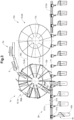
- FIG. 1 shows a schematic side view of a first embodiment of a loading device 10 with a transfer device with a wheel 1, an overhead conveyor device 2 and a feed device 3.
- the wheel 1 is designed to rotate continuously or be rotatable (arrow P1) and has transfer compartments 12 which can receive transport goods T.
- the feed device 3 comprises conveyor belts 31, 32 on which the transport goods T are fed to the wheel 1.
- the transport goods T fall from the inclined conveyor belt 32 into the transfer compartments 12 of the wheel 1 due to gravity.
- the wheel has a side disc 18 which is arranged vertically and delimits the transfer compartments 12 transversely to the direction of rotation (arrow P1).
- the overhead conveyor device 2 comprises a guide rail 21.
- the feed device 3 is arranged in relation to the wheel 1 in such a way that the transport goods T are fed in the same direction as receiving units 4.1 - 4.8.
- receiving units 4.1-4.8 are shown, each of which has carriages 41.1-41.8 and pockets 42.1-42.8, which are firmly connected to one another.
- the pockets 42.1-42.8 have receiving openings 43.1, 43.2, 43.3,... and are designed to receive transport goods T.
- the carriages 41.1 - 41.8 can be conveyed at a variable distance from one another on the guide rail 21 in the direction of the arrow P2.
- the feeding device 10 has a conveyor section 5, in which the receiving units 4.1-4.8 can be conveyed, and a transfer section 6, which overlaps with the conveyor section 5.
- the pockets 42.1-42.8 are conveyed transversely with respect to the conveyor line 5, ie the pockets 42.1-42.8 have their greatest horizontal extent transversely to the conveyor line 5.
- the transfer line 6 is formed by an edge section of the wheel 1 in the lower area of the wheel 1.
- the receiving units are conveyed by the wheel 1 and loaded with the transport goods T.
- the loaded receiving units are then transferred back to the conveyor line 5 by the wheel 1, from where the loaded receiving units are conveyed away.
- the transfer compartments 12 are delimited by first walls 13.1.
- the transfer compartments 12 have second walls 13.2, which are movably attached to the wheel 1.
- the second walls 13.2 can each rest against a first wall 13.1 and together form a double wall.
- the second walls 13.2 are each pivotably mounted about the pivot points 131.1 within a transfer compartment 12 and can be pivoted to guide the transport goods T in the transfer compartments 12, which is illustrated by the arrows P3.
- the first walls 13.1 are fixed and serve as a support surface for the transport goods T in the Transfer compartments 12.
- fastening means designed as pivotable flaps 14 are mounted at end hinge points 131.2 of the first walls 13.1.
- the flaps 14 can be pivoted between a closed position, in which the flaps 14 hold the transport goods T in the transfer compartments 12, and an open position.
- the flaps 14 can serve as a guide for the transport goods T which fall from the conveyor belt 32 into the transfer compartments 12.
- the flaps 14 pivot into the closed position so that the transport goods T are held in the transfer compartments 12.
- the flaps 14 pivot into the open position so that the transport goods T can be released.
- the flaps 14 keep the receiving openings of the receiving units open, which in the Figure 1 at the receiving unit 4.3 and the receiving opening 43.3 of the pocket 42.3.
- the pivoting second walls 13.2 serve as a guide in particular when transferring the transport goods T to the receiving units, which is shown in the Figure 1 for transfer to the receiving units 4.3, 4.4.
- the wheel 1 has engagement means for each transfer compartment 12 on the peripheral edge, which are designed as recesses 11 and which can engage in carrier elements 411.1-411.8 of the transport units 41.1-41.8.
- the guide rail 21 of the overhead conveyor device 2 is designed to be interrupted in the transfer section 6, so that a first guide rail section 211 is arranged upstream of the transfer section 6 and a second guide rail section 212 is arranged downstream of the transfer section 6. On the first guide rail section 211, the transport units with the receiving units to be loaded are fed to the wheel 1 and transferred to the wheel 1.
- the transport units with the loaded receiving units are then transferred to the second guide rail section 212 and conveyed away.
- the transport units 411.1 and 411.2 of the receiving units 4.1 and 4.2 are located in the first guide rail section 211 and the transport units 411.7 and 411.8 of the receiving units 4.7 and 4.8 are located in the second guide rail section 212.
- the first and second guide rail sections 211 and 212 are arranged at the same height.
- the rotating wheel 1, or the transfer compartments 12, and the receiving units in the transfer section 6 move in the same direction and synchronously, so that a reliable and continuous transfer of the transport goods T into the pockets of the receiving units is possible.
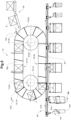
- FIG 2 shows a schematic side view of a second embodiment of a loading device 10a with a transfer device with a wheel 1a, a hanging conveyor device 2a and a feeding device 3a.
- the hanging conveyor device 2a comprises a guide rail 21a.
- the receiving units 4a (for the sake of simplicity, Figure 2 only one of the receiving units is provided with a reference number) each have carriages 41a and pockets 42a, which are fixed are connected to one another.
- the pockets 42a have receiving openings 43a and are designed to receive the transport goods T.
- Pivotable bracket devices 44a are arranged on the pockets 42a, by means of which the receiving openings 43a can be closed and opened, as well as kept open.
- the carriages 41a can be conveyed on the guide rail 21a at a variable distance from one another.
- the loading device 10a has a conveyor section 5a, in which the receiving units 4a can be conveyed, and a transfer section 6a, which overlaps with the conveyor section 5a.
- the transfer section 6a is formed by an edge section in the lower area of the wheel 1a.
- the receiving units 4a are conveyed by the wheel 1a and loaded with the transport goods T.
- the loaded receiving units 4a are then transferred by the wheel 1a back to the conveyor line 5a, from where the loaded receiving units 4a are conveyed away.
- the guide rail 21a of the overhead conveyor device 2a is interrupted in the transfer section 6a, so that a first guide rail section 211a is arranged upstream of the transfer section 6a and a second guide rail section 212a is arranged downstream of the transfer section 6a.
- the first guide rail section 211a and the second guide rail section 212a are arranged at different heights, wherein the height difference of the first and second guide rail sections 211a and 212a is overcome by the wheel 1a.
- the feeding device 3a is arranged relative to the wheel 1a in such a way that the transport goods T are fed in the opposite direction to the receiving units 4a.
- the wheel 1a has transfer compartments 12a which are delimited by first walls 13.1a.
- the transfer compartments 12a have second walls 13.2a which are movable relative to the wheel 1a.
- the second walls 13.2a are each designed to be pivotable within a transfer compartment 12a and serve as a guide when the transport goods T are transferred to the receiving units 4a.
- the first walls 13.1a are designed to be fixed.
- the second walls 13.2a can each rest against a first wall 13.1a and together form a double wall.
- the second walls 13.2a each rest against the first walls 13.1a so that the transport goods T each come to rest on second walls 13.2a.
- the second walls 13.2a each pivot away from the first walls 13.1a, against which they rest, so that the (respectively opposite) first walls 13.1a serve as a support surface for the transport goods T until they are transferred to the receiving units 4a.
- the rotating wheel 1a and the receiving units 4a move in the transfer section 6a in the same direction and synchronously, so that a reliable and continuous transfer of the transport goods T into the pockets 42a of the receiving units 4a is possible.
- FIG 3 shows a schematic side view of a third embodiment of a loading device 10b with a transfer device 1b, an overhead conveyor device 2b and a feed device 3b.
- the overhead conveyor device 2b comprises an interrupted guide rail 21b with a first guide rail section 211b and a second guide rail section 212b.
- the transfer device 1b comprises a first wheel 15.1b and a second wheel 15.2b.
- the two wheels 15.1b and 15.2b are operatively connected by a belt 16b and can thus be rotated synchronously.
- the feed device 3b guides transport goods T to the first wheel 15.1b, which transfers the transport goods T to receiving units 4b.
- the receiving units 4b each comprise a pocket 42b and a transport unit, which is designed as a carriage 41b that can be conveyed in the guide rail 21b.
- the first wheel 15.1b has transfer compartments 12b, which are delimited by first walls 13.1b.
- the first wheel 15.1b has second walls 13.1b, which are movable relative to the first wheel 15.1b.
- the second walls 13.2b are each designed to be pivotable within a transfer compartment 12b and form a guide when the transport goods T are transferred to the receiving units 4b. When the transport goods T are taken over from the feed device 3b, the transport goods T come to rest on the second walls 13.2b.
- the second walls 13.2b pivot so that the transport goods T come to rest on the first walls 13.1b, which are designed to be fixed.
- the second walls 13.2b pivot in the direction of arrow P31 until they rest on the transport goods T and clamp them in the transfer compartment 12b.
- the second walls 13.2b are mounted in such a way that they pivot in the direction of the arrow P32 shortly before the transport goods T are handed over to the receiving units 4b and thus release the transport goods T.
- the second wheel 1 5.2b has spokes 17b, which come into active connection with the carriages 41b of the receiving units 4b and can transfer the carriages 41b into the second guide rail section 212b arranged downstream. Although in the Figure 3 not shown, it is possible to use the second wheel 15.2b to transfer further transport goods T analogously to the first wheel 15.1b into the receiving units 4b fed by the first wheel 15.1b.
- the conveyance of the receiving units 4b between the wheels 15.1b and 15.2b is in the Figure 3 only indicated schematically.
- the conveyance of the receiving units 4b between the wheels 15.1b and 15.2b can be carried out by suitable conveying means, such as a chain.
- FIG 4 shows a schematic side view of a fourth embodiment of a loading device 10c with a feed device 3c, a hanging conveyor device 2c and a transfer device with a wheel 1c.
- the hanging conveyor device 2c comprises a guide rail 21c.
- the loading device 10c has receiving units 4c, each of which has a pocket 42c and a transport unit designed as a carriage 41c.
- the carriages 41c can be conveyed on the guide rail 21c with a variable distance.
- the pockets 42c are conveyed longitudinally with respect to the conveyor line 5c and the transfer line 6c, ie the pockets 42c are conveyed along the conveyor line 5c and the transfer section 6c have their greatest horizontal extent.
- the transport goods T are accordingly fed lengthwise on the feed device 3c and conveyed lengthwise in the wheel 1c.
- the guide rail 21c is formed continuously in the transfer section 5c, although in the Figure 5 this part of the guide rail 21c is shown in dashed lines for the sake of better clarity.
- the guide rail 21c can be designed to be continuous in the transfer section 5c due to the longitudinally oriented transfer of the transport goods T to the pockets 42c, without getting in the way of the transfer of the transport goods T to the pockets 42c.
- FIG. 5 shows a schematic side view of a fifth embodiment of a loading device 10d with a feed device 3d, an overhead conveyor device 2d and a transfer device 1d.
- the overhead conveyor device 2d comprises a guide rail 21d.
- the transfer device comprises a circular track 1d with an upper run 16.1d and a lower run 16.2d.
- the circular track 1d has a first deflection roller 15.1d and a second deflection roller 15.2d.
- the feed device 3d supplies transport goods T, which are taken over by the circular track 1d in front of the upper run 16.1d and conveyed from the upper run 16.1d to the lower run 16.2d.
- the transport goods T are transferred from the lower run 16.2d to the receiving units 4d.
- the circular track 1d has transfer compartments 12d which are delimited by first and second walls 13.1d and 13.2d and in which the transport goods T can be accommodated.
- first and second walls 13.1d and 13.2d On the first walls 13.1d, pivotable flaps 14d are attached between an open and closed position, which can hold the transport goods T in the transfer compartments 12d in the closed position.
- the receiving units 4d each comprise a pocket 42d and a transport unit, which is designed as a carriage 41d that can be conveyed in the guide rail 21d.
- Alignment means are attached to the carriage 41d (not shown in Figure 5), which change the orientation of the pockets 42d shortly before the transport goods T are transferred from a transverse orientation to a longitudinal orientation (arrow P4).
- the transport goods T are fed in a longitudinal orientation by the feed device 3d and conveyed in a longitudinal orientation by the round track 1d and transferred to the pockets 42d.
- the orientation of the pockets 42d is changed from the longitudinal orientation to the transverse orientation again by the alignment means after the transport goods T have been transferred.
- the guide rail 21d is designed to be continuous in the transfer section 6d. Due to the longitudinally oriented transfer of the transport goods T to the pockets 42d, the guide rail 21d can be designed to be continuous in the transfer section 6d without the guide rail 21d getting in the way of the transfer of the transport goods T to the pockets 42d.
Landscapes
- Engineering & Computer Science (AREA)
- Mechanical Engineering (AREA)
- Intermediate Stations On Conveyors (AREA)
- Charge And Discharge Circuits For Batteries Or The Like (AREA)
- Vehicle Body Suspensions (AREA)
- Meter Arrangements (AREA)
Claims (10)
- Dispositif de chargement (10, 10a-d) pour le chargement continu d'unités de réception (4.1-4.8, 4a-d) avec des marchandises à transporter (T), le dispositif de chargement (10, 10a-d) comprenant une pluralité d'unités de réception (4.1-4.8, 4ad), un dispositif de transport (2, 2a-d), le dispositif de transport (2, 2a-d) étant un dispositif de transport suspendu (2, 2a-d) avec un rail de roulement (21, 21a-d), les unités de transport sur le rail de roulement (21, 21a-d) sont transportable avec un écart variable les unes par rapport aux autres, des chariots (41 .1 -41 .8, 41a-d), dans lequel les unités de réception (4.1-4.8, 4a-d) sont transportable, un dispositif d'amenée (3, 3a-d) pour amener des marchandises à transporter (T), un dispositif de transfert (1, 1a-d), qui est conçu pour prendre en charge les marchandises à transporter (T) du dispositif d'amenée (3, 3a-d), les transporter et les transférer aux unités de réception (4.1 -4.8, 4a-d), le dispositif de transfert (1, 1a-d) et les unités de réception (4.1 -4.8, 4a-d) sont déplacées dans le même sens lors du transfert des marchandises à transporter (T), caractérisé en ce que le dispositif de transfert (1, 1a-d) comprenant des casiers de transfert (12, 12a, 12b, 12d) pour recevoir les marchandises à transporter (T), lesquels comprenant des moyens de butée mobiles qui sont déplacés entre une position fermée et une position ouverte et qui, dans la position fermée, maintiennent les marchandises à transporter (T) dans le casier de transfert respectif (12, 12a, 12b, 12d), les moyens de butée de préférence sont commandés.
- Dispositif de chargement (10, 10a-d) selon la revendication 1,caractérisé en ce que les moyens de butée mobiles ouvrent et/ou maintiennent ouverte une ouverture de réception (43.1, 43.2, 43.3) d'une unité de réception (4.1-4.8) à charger lors du déplacement de la position fermée à la position ouverte.
- Dispositif de chargement (10, 10a-d) selon la revendication 2, caractérisé en ce que les moyens de butée sont déplacés de la position fermée à la position ouverte peu avant le transfert des marchandises à transporter (T) aux unités de réception (4.1-4.8).
- Dispositif de chargement (10, 10a-d) selon l'une des revendications précédentes, caractérisé en ce que les moyens de butée sont réalisés sous forme de clapets pivotants (14) qui sont disposés sur les parois des compartiments de transfert (12, 12a, 12b, 12d).
- Dispositif de chargement (10, 10a-d) selon la revendication 4, caractérisé en ce que les volets (14) forment, dans une position ouverte, un élargissement des parois des compartiments de transfert (12, 12a, 1 2b, 12d) et guident ainsi les marchandises transportées (T).
- Dispositif de chargement (10, 10a-d) selon l'une des revendications précédentes, caractérisé en ce que le dispositif de transfert (1, 1a-d) comprenant des moyens d'engagement (11) qui sont reliés fonctionnellement aux unités de réception (4.1 - 4.8, 4a-d).
- Dispositif de chargement (10, 10a-d) selon l'une des revendications précédentes, caractérisé en ce que le dispositif de chargement (10, 10a-d) comprenant des moyens d'alignement pour aligner l'orientation de poches (42.1-42.8, 42a-d) avant et/ou lors et/ou après le transfert des marchandises transportées (T) vers les poches (42.1-42.8, 42a-d).
- Dispositif de chargement (10, 10a-d), selon la revendication 7, caractérisé en ce que des moyens d'alignement sont disposés au dispositif de transport suspendu (2, 2ad) ou au dispositif de transfert (1, 1a-d).
- Dispositif de chargement (10, 10a-d) selon l'une des revendications précédentes, caractérisé en ce que le dispositif de chargement (10, 10a-d) comprenant des moyens d'ouverture qui sont conçus pour ouvrir et/ou maintenir ouverte une ouverture de réception (43.1, 43.2, 43.3, ...) d'une unité de réception (4.1-4.8, 4a-d) à charger.
- Dispositif de chargement (10, 10a-d) selon la revendication 9, caractérisé en ce que les moyens d'ouverture sont disposés sur le dispositif de transport suspendu (2, 2ad) ou sur le dispositif de transfert (1, 1a-d).
Applications Claiming Priority (2)
| Application Number | Priority Date | Filing Date | Title |
|---|---|---|---|
| CH00085/17A CH713387A1 (de) | 2017-01-26 | 2017-01-26 | Beschickungsvorrichtung zum kontinuierlichen Beschicken von Aufnahmeeinheiten mit Transportgütern. |
| EP18151147.8A EP3354605B1 (fr) | 2017-01-26 | 2018-01-11 | Dispositif de chargement |
Related Parent Applications (1)
| Application Number | Title | Priority Date | Filing Date |
|---|---|---|---|
| EP18151147.8A Division EP3354605B1 (fr) | 2017-01-26 | 2018-01-11 | Dispositif de chargement |
Publications (2)
| Publication Number | Publication Date |
|---|---|
| EP4079663A1 EP4079663A1 (fr) | 2022-10-26 |
| EP4079663B1 true EP4079663B1 (fr) | 2024-11-06 |
Family
ID=60954930
Family Applications (2)
| Application Number | Title | Priority Date | Filing Date |
|---|---|---|---|
| EP22178665.0A Active EP4079663B1 (fr) | 2017-01-26 | 2018-01-11 | Dispositif de chargement |
| EP18151147.8A Active EP3354605B1 (fr) | 2017-01-26 | 2018-01-11 | Dispositif de chargement |
Family Applications After (1)
| Application Number | Title | Priority Date | Filing Date |
|---|---|---|---|
| EP18151147.8A Active EP3354605B1 (fr) | 2017-01-26 | 2018-01-11 | Dispositif de chargement |
Country Status (5)
| Country | Link |
|---|---|
| US (1) | US10358299B2 (fr) |
| EP (2) | EP4079663B1 (fr) |
| CN (1) | CN108454960B (fr) |
| CH (1) | CH713387A1 (fr) |
| ES (1) | ES2921126T3 (fr) |
Families Citing this family (21)
| Publication number | Priority date | Publication date | Assignee | Title |
|---|---|---|---|---|
| ITBO20130685A1 (it) * | 2013-12-13 | 2015-06-14 | Marchesini Group Spa | Dispositivo di trasferimento di foglietti informativi |
| CH713399A1 (de) | 2017-01-31 | 2018-07-31 | Ferag Ag | Fördereinheit zum hängenden Transport von Transportelementen in zwei Positionen. |
| CH713398A1 (de) * | 2017-01-31 | 2018-07-31 | Ferag Ag | Vorrichtung zum Entleeren hängend geförderter Transporttaschen. |
| US11878876B2 (en) | 2017-01-31 | 2024-01-23 | Ferag Ag | Device for emptying transport bags conveyed in a suspended manner |
| DE102018209266A1 (de) * | 2018-06-11 | 2019-12-12 | Dürkopp Fördertechnik GmbH | Vorrichtung und Verfahren zum auftragsorientierten Bereitstellen von Einzelwaren mehrerer Aufträge an einem Packplatz |
| DE102018219583C5 (de) | 2018-11-15 | 2025-09-11 | Dürkopp Fördertechnik GmbH | Förderanlage und Verfahren zum Fördern von Waren |
| GB201900818D0 (en) * | 2019-01-21 | 2019-03-13 | Mars Inc | Container processing apparatus |
| CH716519A1 (de) | 2019-08-22 | 2021-02-26 | Ferag Ag | Vorrichtung und Verfahren zum Transferieren von Waren-Einheiten in Fördereinheiten und/oder aus Fördereinheiten eines Hängefördersystems. |
| IT202100000872A1 (it) * | 2021-01-19 | 2022-07-19 | Dolcepack Sagl | Macchina di confezionamento a giostra |
| CN113060359A (zh) * | 2021-04-22 | 2021-07-02 | 泉州市咪童贸易有限公司 | 一种电子产品用手机包装盒输送设备 |
| JP7663436B2 (ja) * | 2021-07-07 | 2025-04-16 | 東芝テック株式会社 | 袋詰め装置 |
| WO2023095049A1 (fr) | 2021-11-29 | 2023-06-01 | Ferag Ag | Dispositif de gestion du chargement d'unités de transport d'un système d'acheminement |
| JP7681312B2 (ja) * | 2021-12-16 | 2025-05-22 | 株式会社古川製作所 | トレー挿入装置及び包装機 |
| EP4242142A1 (fr) * | 2022-03-08 | 2023-09-13 | Ferag Ag | Dispositif, procédé et système de préparation de commandes de marchandises de détail |
| EP4310034A3 (fr) | 2022-05-31 | 2024-04-10 | Ferag Ag | Dispositif et procédé de chargement de conteneurs de transport |
| US12246872B2 (en) | 2022-05-31 | 2025-03-11 | Ferag Ag | Device and method for loading transport containers |
| EP4342822A1 (fr) * | 2022-09-20 | 2024-03-27 | BEUMER Group GmbH & Co. KG | Station de chargement de poches pour charger et/ou décharger des sacs de transport d'un convoyeur aérien et procédé correspondant |
| CN115959463B (zh) * | 2022-12-02 | 2025-12-19 | 西南石油大学 | 一种高处坠落物防冲击保护传递方法 |
| CN117088024B (zh) * | 2023-08-31 | 2025-12-05 | 亚杰科技(江苏)有限公司 | 一种智能仓储物料分配设备 |
| CH721462A1 (de) | 2023-12-22 | 2025-06-30 | Ferag Ag | Anlage und Verfahren zum Sortieren und Zwischenspeichern von Stückgütern |
| CN119929269A (zh) * | 2025-03-19 | 2025-05-06 | 成都潇智源裕科技有限公司 | 一种包装机 |
Citations (2)
| Publication number | Priority date | Publication date | Assignee | Title |
|---|---|---|---|---|
| WO2010085141A1 (fr) * | 2009-01-22 | 2010-07-29 | Marel Stork Poultry Processing B.V. | Système transporteur suspendu pour transporter des barquettes d'emballage |
| EP2499069B1 (fr) * | 2009-11-12 | 2013-08-07 | Lorenzo Forni | Aligneuse pour contenants et procédé associé |
Family Cites Families (17)
| Publication number | Priority date | Publication date | Assignee | Title |
|---|---|---|---|---|
| US2796974A (en) * | 1953-05-05 | 1957-06-25 | Schloemann Ag | Article transfer mechanism |
| US3064406A (en) * | 1957-09-20 | 1962-11-20 | Kennedy Edward | Article counting and loading machine |
| FR2637274A1 (fr) * | 1988-10-04 | 1990-04-06 | Ano Sarl | Trieurs convoyeurs d'objets automatiques |
| DE4201080A1 (de) * | 1992-01-17 | 1993-07-22 | Ostma Maschinenbau Gmbh | Vorrichtung zum beschicken einer verpackungsaufnahme z. b. eines offenen kartons |
| EP0638501B1 (fr) * | 1993-08-10 | 1996-12-18 | Grapha-Holding Ag | Dispositif convoyeur pour le transport ultérieur de produits plats, alimentés un par un |
| EP0676354B1 (fr) * | 1994-04-08 | 2000-08-16 | Ferag AG | Procédé et dispositif pour emballer des produits imprimés |
| DE10110787A1 (de) * | 2001-03-06 | 2002-09-12 | Focke & Co | Verfahren und Vorrichtung zum Verpacken von länglichen Gegenständen |
| CN1803553A (zh) * | 2005-12-30 | 2006-07-19 | 王树生 | 积放式输送机升降平移装置 |
| DE102008061685A1 (de) | 2008-12-11 | 2010-06-17 | Dürkopp Adler AG | Belade-Station für in einer Hänge-Förder-Anlage transportierte Transport-Taschen |
| DE102009013434A1 (de) * | 2009-03-18 | 2010-09-23 | Zahoransky Ag | Sortiervorrichtung |
| DE102009026043A1 (de) * | 2009-06-26 | 2010-12-30 | Krones Ag | Vorrichtung und Verfahren zum Beschicken einer Weiterverarbeitungseinheit mit Artikeln |
| DE102010033905A1 (de) * | 2010-08-10 | 2012-02-16 | Dürkopp Fördertechnik GmbH | Förderanlage mit Tragetaschen für Fördergut |
| JP5650556B2 (ja) * | 2011-02-15 | 2015-01-07 | 東洋自動機株式会社 | 間欠回転式ロータリー型袋詰め包装機における被包装物充填方法及び装置 |
| US8490774B2 (en) * | 2011-02-24 | 2013-07-23 | Dürkopp Fördertechnik GmbH | Loading station for transport bags transported in an overhead conveyor system |
| DE102012018925B4 (de) | 2012-09-18 | 2020-06-18 | Ssi Schäfer Automation Gmbh | Tasche für Hängeförderer, Beladestation, Entladestation und Taschen-Hängeförderanlage |
| CH710650A1 (de) * | 2015-01-26 | 2016-07-29 | Ferag Ag | Transportvorrichtung, insbesondere in Form eines Hängeförderers. |
| CH711809A1 (de) * | 2015-11-25 | 2017-05-31 | Ferag Ag | Vorrichtung zum Beschicken von Transporttaschen. |
-
2017
- 2017-01-26 CH CH00085/17A patent/CH713387A1/de not_active Application Discontinuation
-
2018
- 2018-01-11 ES ES18151147T patent/ES2921126T3/es active Active
- 2018-01-11 EP EP22178665.0A patent/EP4079663B1/fr active Active
- 2018-01-11 EP EP18151147.8A patent/EP3354605B1/fr active Active
- 2018-01-22 CN CN201810058237.3A patent/CN108454960B/zh not_active Expired - Fee Related
- 2018-01-23 US US15/877,596 patent/US10358299B2/en active Active
Patent Citations (2)
| Publication number | Priority date | Publication date | Assignee | Title |
|---|---|---|---|---|
| WO2010085141A1 (fr) * | 2009-01-22 | 2010-07-29 | Marel Stork Poultry Processing B.V. | Système transporteur suspendu pour transporter des barquettes d'emballage |
| EP2499069B1 (fr) * | 2009-11-12 | 2013-08-07 | Lorenzo Forni | Aligneuse pour contenants et procédé associé |
Also Published As
| Publication number | Publication date |
|---|---|
| CN108454960B (zh) | 2022-01-07 |
| EP3354605B1 (fr) | 2022-06-15 |
| CH713387A1 (de) | 2018-07-31 |
| ES2921126T3 (es) | 2022-08-18 |
| CN108454960A (zh) | 2018-08-28 |
| EP3354605A1 (fr) | 2018-08-01 |
| US10358299B2 (en) | 2019-07-23 |
| US20180208407A1 (en) | 2018-07-26 |
| EP4079663A1 (fr) | 2022-10-26 |
Similar Documents
| Publication | Publication Date | Title |
|---|---|---|
| EP3354605B1 (fr) | Dispositif de chargement | |
| AT521110B1 (de) | Entladestation und Verfahren zum Entladen eines mit einem Fördergut beladenen Fördergutbehälters | |
| EP3250486B1 (fr) | Procédé pour remplir les poches d'un dispositif de transport sous la forme d'un convoyeur aérien et dispositif pour la mise en oeuvre de ce procédé | |
| EP3577041B1 (fr) | Dispositif et procédé pour faire tourner, ouvrir et remplir des sacs de transport qui sont transportés suspendus | |
| EP3782936B1 (fr) | Sac de transport pour un système de transport suspendu | |
| DE102006034395B4 (de) | Vorrichtung zum Transportieren von Gegenständen | |
| EP2321206B1 (fr) | Dispositif de stockage intermédiaire et procédé pour son fonctionnement | |
| EP3505468A2 (fr) | Dispositif de chargement et de déchargement des systèmes de convoyeurs suspendus sur rails | |
| EP1169249B1 (fr) | Procede et dispositif pour transporter des produits en vrac | |
| EP2192061B1 (fr) | Dispositif de transfert, de stockage intermédiaire et de transmission de produits unitaires longitudinaux et cylindriques creux ainsi que procédé de fonctionnement d'un tel dispositif | |
| CH711791A1 (de) | Fördersystem. | |
| EP2297014B1 (fr) | Dispositif d'insertion et procédé d'insertion | |
| DE4216721A1 (de) | Verfahren und Vorrichtung zum Ein- oder Auspacken von Artikeln in Gebinde oder aus Gebinden | |
| DE10236168B3 (de) | Transportsystem für Stückgutbehälter, insbesondere für Gepäckbehälter | |
| DE4033184C2 (de) | Umlaufregallager-System | |
| EP3305691A1 (fr) | Système de transport doté d'un dispositif de guidage | |
| DE102007004324B4 (de) | Transporteinrichtung zum Transport von Gegenständen | |
| DE60222660T2 (de) | Vorrichtung für individuelle höhensortierung von platten | |
| DE1922739A1 (de) | Verfahren und Vorrichtung zum kontinuierlichen Einpacken von Flaschen in Kaesten u.dgl. | |
| EP2216280A1 (fr) | Dispositif et procédé de transfert d'objets plats flexibles | |
| DE10341749A1 (de) | Vorrichtung zum Einführen von Beuteln in einen Karton | |
| EP3214023A2 (fr) | Dispositif de transport avec un convoyeur en chaîne | |
| EP4491544A2 (fr) | Système de transport et procédé de fonctionnement d'un système de transport | |
| DE3937776A1 (de) | Vorrichtung zum zwischenspeichern von formatvariablem stueckgut | |
| DE102022127240A1 (de) | Behältertransportvorrichtung mit einer Führungsvorrichtung und Verfahren zum Transportieren von Behältern |
Legal Events
| Date | Code | Title | Description |
|---|---|---|---|
| PUAI | Public reference made under article 153(3) epc to a published international application that has entered the european phase |
Free format text: ORIGINAL CODE: 0009012 |
|
| STAA | Information on the status of an ep patent application or granted ep patent |
Free format text: STATUS: THE APPLICATION HAS BEEN PUBLISHED |
|
| AC | Divisional application: reference to earlier application |
Ref document number: 3354605 Country of ref document: EP Kind code of ref document: P |
|
| AK | Designated contracting states |
Kind code of ref document: A1 Designated state(s): AL AT BE BG CH CY CZ DE DK EE ES FI FR GB GR HR HU IE IS IT LI LT LU LV MC MK MT NL NO PL PT RO RS SE SI SK SM TR |
|
| STAA | Information on the status of an ep patent application or granted ep patent |
Free format text: STATUS: REQUEST FOR EXAMINATION WAS MADE |
|
| 17P | Request for examination filed |
Effective date: 20230113 |
|
| RBV | Designated contracting states (corrected) |
Designated state(s): AL AT BE BG CH CY CZ DE DK EE ES FI FR GB GR HR HU IE IS IT LI LT LU LV MC MK MT NL NO PL PT RO RS SE SI SK SM TR |
|
| P01 | Opt-out of the competence of the unified patent court (upc) registered |
Effective date: 20230507 |
|
| GRAP | Despatch of communication of intention to grant a patent |
Free format text: ORIGINAL CODE: EPIDOSNIGR1 |
|
| STAA | Information on the status of an ep patent application or granted ep patent |
Free format text: STATUS: GRANT OF PATENT IS INTENDED |
|
| INTG | Intention to grant announced |
Effective date: 20240603 |
|
| GRAS | Grant fee paid |
Free format text: ORIGINAL CODE: EPIDOSNIGR3 |
|
| GRAA | (expected) grant |
Free format text: ORIGINAL CODE: 0009210 |
|
| STAA | Information on the status of an ep patent application or granted ep patent |
Free format text: STATUS: THE PATENT HAS BEEN GRANTED |
|
| AC | Divisional application: reference to earlier application |
Ref document number: 3354605 Country of ref document: EP Kind code of ref document: P |
|
| AK | Designated contracting states |
Kind code of ref document: B1 Designated state(s): AL AT BE BG CH CY CZ DE DK EE ES FI FR GB GR HR HU IE IS IT LI LT LU LV MC MK MT NL NO PL PT RO RS SE SI SK SM TR |
|
| REG | Reference to a national code |
Ref country code: GB Ref legal event code: FG4D Free format text: NOT ENGLISH |
|
| REG | Reference to a national code |
Ref country code: CH Ref legal event code: EP |
|
| REG | Reference to a national code |
Ref country code: DE Ref legal event code: R096 Ref document number: 502018015311 Country of ref document: DE |
|
| REG | Reference to a national code |
Ref country code: IE Ref legal event code: FG4D Free format text: LANGUAGE OF EP DOCUMENT: GERMAN |
|
| REG | Reference to a national code |
Ref country code: ES Ref legal event code: FG2A Ref document number: 2994767 Country of ref document: ES Kind code of ref document: T3 Effective date: 20250131 |
|
| REG | Reference to a national code |
Ref country code: NL Ref legal event code: FP |
|
| REG | Reference to a national code |
Ref country code: LT Ref legal event code: MG9D |
|
| PG25 | Lapsed in a contracting state [announced via postgrant information from national office to epo] |
Ref country code: IS Free format text: LAPSE BECAUSE OF FAILURE TO SUBMIT A TRANSLATION OF THE DESCRIPTION OR TO PAY THE FEE WITHIN THE PRESCRIBED TIME-LIMIT Effective date: 20250306 Ref country code: HR Free format text: LAPSE BECAUSE OF FAILURE TO SUBMIT A TRANSLATION OF THE DESCRIPTION OR TO PAY THE FEE WITHIN THE PRESCRIBED TIME-LIMIT Effective date: 20241106 Ref country code: PT Free format text: LAPSE BECAUSE OF FAILURE TO SUBMIT A TRANSLATION OF THE DESCRIPTION OR TO PAY THE FEE WITHIN THE PRESCRIBED TIME-LIMIT Effective date: 20250306 |
|
| PG25 | Lapsed in a contracting state [announced via postgrant information from national office to epo] |
Ref country code: FI Free format text: LAPSE BECAUSE OF FAILURE TO SUBMIT A TRANSLATION OF THE DESCRIPTION OR TO PAY THE FEE WITHIN THE PRESCRIBED TIME-LIMIT Effective date: 20241106 |
|
| PG25 | Lapsed in a contracting state [announced via postgrant information from national office to epo] |
Ref country code: BG Free format text: LAPSE BECAUSE OF FAILURE TO SUBMIT A TRANSLATION OF THE DESCRIPTION OR TO PAY THE FEE WITHIN THE PRESCRIBED TIME-LIMIT Effective date: 20241106 |
|
| PG25 | Lapsed in a contracting state [announced via postgrant information from national office to epo] |
Ref country code: NO Free format text: LAPSE BECAUSE OF FAILURE TO SUBMIT A TRANSLATION OF THE DESCRIPTION OR TO PAY THE FEE WITHIN THE PRESCRIBED TIME-LIMIT Effective date: 20250206 |
|
| PG25 | Lapsed in a contracting state [announced via postgrant information from national office to epo] |
Ref country code: GR Free format text: LAPSE BECAUSE OF FAILURE TO SUBMIT A TRANSLATION OF THE DESCRIPTION OR TO PAY THE FEE WITHIN THE PRESCRIBED TIME-LIMIT Effective date: 20250207 Ref country code: LV Free format text: LAPSE BECAUSE OF FAILURE TO SUBMIT A TRANSLATION OF THE DESCRIPTION OR TO PAY THE FEE WITHIN THE PRESCRIBED TIME-LIMIT Effective date: 20241106 |
|
| PG25 | Lapsed in a contracting state [announced via postgrant information from national office to epo] |
Ref country code: PL Free format text: LAPSE BECAUSE OF FAILURE TO SUBMIT A TRANSLATION OF THE DESCRIPTION OR TO PAY THE FEE WITHIN THE PRESCRIBED TIME-LIMIT Effective date: 20241106 |
|
| PG25 | Lapsed in a contracting state [announced via postgrant information from national office to epo] |
Ref country code: RS Free format text: LAPSE BECAUSE OF FAILURE TO SUBMIT A TRANSLATION OF THE DESCRIPTION OR TO PAY THE FEE WITHIN THE PRESCRIBED TIME-LIMIT Effective date: 20250206 |
|
| PG25 | Lapsed in a contracting state [announced via postgrant information from national office to epo] |
Ref country code: SM Free format text: LAPSE BECAUSE OF FAILURE TO SUBMIT A TRANSLATION OF THE DESCRIPTION OR TO PAY THE FEE WITHIN THE PRESCRIBED TIME-LIMIT Effective date: 20241106 |
|
| PG25 | Lapsed in a contracting state [announced via postgrant information from national office to epo] |
Ref country code: DK Free format text: LAPSE BECAUSE OF FAILURE TO SUBMIT A TRANSLATION OF THE DESCRIPTION OR TO PAY THE FEE WITHIN THE PRESCRIBED TIME-LIMIT Effective date: 20241106 |
|
| PG25 | Lapsed in a contracting state [announced via postgrant information from national office to epo] |
Ref country code: EE Free format text: LAPSE BECAUSE OF FAILURE TO SUBMIT A TRANSLATION OF THE DESCRIPTION OR TO PAY THE FEE WITHIN THE PRESCRIBED TIME-LIMIT Effective date: 20241106 |
|
| PG25 | Lapsed in a contracting state [announced via postgrant information from national office to epo] |
Ref country code: RO Free format text: LAPSE BECAUSE OF FAILURE TO SUBMIT A TRANSLATION OF THE DESCRIPTION OR TO PAY THE FEE WITHIN THE PRESCRIBED TIME-LIMIT Effective date: 20241106 |
|
| PG25 | Lapsed in a contracting state [announced via postgrant information from national office to epo] |
Ref country code: SK Free format text: LAPSE BECAUSE OF FAILURE TO SUBMIT A TRANSLATION OF THE DESCRIPTION OR TO PAY THE FEE WITHIN THE PRESCRIBED TIME-LIMIT Effective date: 20241106 |
|
| PG25 | Lapsed in a contracting state [announced via postgrant information from national office to epo] |
Ref country code: CZ Free format text: LAPSE BECAUSE OF FAILURE TO SUBMIT A TRANSLATION OF THE DESCRIPTION OR TO PAY THE FEE WITHIN THE PRESCRIBED TIME-LIMIT Effective date: 20241106 |
|
| PG25 | Lapsed in a contracting state [announced via postgrant information from national office to epo] |
Ref country code: IT Free format text: LAPSE BECAUSE OF FAILURE TO SUBMIT A TRANSLATION OF THE DESCRIPTION OR TO PAY THE FEE WITHIN THE PRESCRIBED TIME-LIMIT Effective date: 20241106 |
|
| REG | Reference to a national code |
Ref country code: DE Ref legal event code: R097 Ref document number: 502018015311 Country of ref document: DE |
|
| REG | Reference to a national code |
Ref country code: DE Ref legal event code: R082 Ref document number: 502018015311 Country of ref document: DE Representative=s name: RENTSCH LEGAL PARTNERS GMBH, DE |
|
| PG25 | Lapsed in a contracting state [announced via postgrant information from national office to epo] |
Ref country code: SE Free format text: LAPSE BECAUSE OF FAILURE TO SUBMIT A TRANSLATION OF THE DESCRIPTION OR TO PAY THE FEE WITHIN THE PRESCRIBED TIME-LIMIT Effective date: 20241106 |
|
| PLBE | No opposition filed within time limit |
Free format text: ORIGINAL CODE: 0009261 |
|
| STAA | Information on the status of an ep patent application or granted ep patent |
Free format text: STATUS: NO OPPOSITION FILED WITHIN TIME LIMIT |
|
| PG25 | Lapsed in a contracting state [announced via postgrant information from national office to epo] |
Ref country code: MC Free format text: LAPSE BECAUSE OF FAILURE TO SUBMIT A TRANSLATION OF THE DESCRIPTION OR TO PAY THE FEE WITHIN THE PRESCRIBED TIME-LIMIT Effective date: 20241106 Ref country code: LU Free format text: LAPSE BECAUSE OF NON-PAYMENT OF DUE FEES Effective date: 20250111 |
|
| 26N | No opposition filed |
Effective date: 20250807 |
|
| PG25 | Lapsed in a contracting state [announced via postgrant information from national office to epo] |
Ref country code: BE Free format text: LAPSE BECAUSE OF NON-PAYMENT OF DUE FEES Effective date: 20250131 |
|
| PG25 | Lapsed in a contracting state [announced via postgrant information from national office to epo] |
Ref country code: FR Free format text: LAPSE BECAUSE OF NON-PAYMENT OF DUE FEES Effective date: 20250131 |
|
| REG | Reference to a national code |
Ref country code: BE Ref legal event code: MM Effective date: 20250131 |
|
| PG25 | Lapsed in a contracting state [announced via postgrant information from national office to epo] |
Ref country code: IE Free format text: LAPSE BECAUSE OF NON-PAYMENT OF DUE FEES Effective date: 20250111 |
|
| REG | Reference to a national code |
Ref country code: CH Ref legal event code: U11 Free format text: ST27 STATUS EVENT CODE: U-0-0-U10-U11 (AS PROVIDED BY THE NATIONAL OFFICE) Effective date: 20260201 |
|
| PGFP | Annual fee paid to national office [announced via postgrant information from national office to epo] |
Ref country code: NL Payment date: 20260121 Year of fee payment: 9 |
|
| REG | Reference to a national code |
Ref country code: CH Ref legal event code: R18 Free format text: ST27 STATUS EVENT CODE: U-0-0-R10-R18 (AS PROVIDED BY THE NATIONAL OFFICE) Effective date: 20260408 |
|
| PGFP | Annual fee paid to national office [announced via postgrant information from national office to epo] |
Ref country code: GB Payment date: 20260123 Year of fee payment: 9 |
|
| PGFP | Annual fee paid to national office [announced via postgrant information from national office to epo] |
Ref country code: ES Payment date: 20260227 Year of fee payment: 9 |
|
| PGFP | Annual fee paid to national office [announced via postgrant information from national office to epo] |
Ref country code: DE Payment date: 20260121 Year of fee payment: 9 |
|
| PGFP | Annual fee paid to national office [announced via postgrant information from national office to epo] |
Ref country code: AT Payment date: 20260122 Year of fee payment: 9 |
|
| PGFP | Annual fee paid to national office [announced via postgrant information from national office to epo] |
Ref country code: CH Payment date: 20260201 Year of fee payment: 9 |