EP3577363B1 - Freinage electromechanique pour un axe, et electromoteur avec un tel freinage - Google Patents
Freinage electromechanique pour un axe, et electromoteur avec un tel freinage Download PDFInfo
- Publication number
- EP3577363B1 EP3577363B1 EP18702054.0A EP18702054A EP3577363B1 EP 3577363 B1 EP3577363 B1 EP 3577363B1 EP 18702054 A EP18702054 A EP 18702054A EP 3577363 B1 EP3577363 B1 EP 3577363B1
- Authority
- EP
- European Patent Office
- Prior art keywords
- magnetic body
- brake
- brake arrangement
- region
- stud
- Prior art date
- Legal status (The legal status is an assumption and is not a legal conclusion. Google has not performed a legal analysis and makes no representation as to the accuracy of the status listed.)
- Active
Links
Images



Classifications
-
- F—MECHANICAL ENGINEERING; LIGHTING; HEATING; WEAPONS; BLASTING
- F16—ENGINEERING ELEMENTS AND UNITS; GENERAL MEASURES FOR PRODUCING AND MAINTAINING EFFECTIVE FUNCTIONING OF MACHINES OR INSTALLATIONS; THERMAL INSULATION IN GENERAL
- F16D—COUPLINGS FOR TRANSMITTING ROTATION; CLUTCHES; BRAKES
- F16D55/00—Brakes with substantially-radial braking surfaces pressed together in axial direction, e.g. disc brakes
-
- F—MECHANICAL ENGINEERING; LIGHTING; HEATING; WEAPONS; BLASTING
- F16—ENGINEERING ELEMENTS AND UNITS; GENERAL MEASURES FOR PRODUCING AND MAINTAINING EFFECTIVE FUNCTIONING OF MACHINES OR INSTALLATIONS; THERMAL INSULATION IN GENERAL
- F16D—COUPLINGS FOR TRANSMITTING ROTATION; CLUTCHES; BRAKES
- F16D55/00—Brakes with substantially-radial braking surfaces pressed together in axial direction, e.g. disc brakes
- F16D55/02—Brakes with substantially-radial braking surfaces pressed together in axial direction, e.g. disc brakes with axially-movable discs or pads pressed against axially-located rotating members
- F16D55/22—Brakes with substantially-radial braking surfaces pressed together in axial direction, e.g. disc brakes with axially-movable discs or pads pressed against axially-located rotating members by clamping an axially-located rotating disc between movable braking members, e.g. movable brake discs or brake pads
-
- F—MECHANICAL ENGINEERING; LIGHTING; HEATING; WEAPONS; BLASTING
- F16—ENGINEERING ELEMENTS AND UNITS; GENERAL MEASURES FOR PRODUCING AND MAINTAINING EFFECTIVE FUNCTIONING OF MACHINES OR INSTALLATIONS; THERMAL INSULATION IN GENERAL
- F16D—COUPLINGS FOR TRANSMITTING ROTATION; CLUTCHES; BRAKES
- F16D63/00—Brakes not otherwise provided for; Brakes combining more than one of the types of groups F16D49/00 - F16D61/00
- F16D63/002—Brakes with direct electrical or electro-magnetic actuation
-
- F—MECHANICAL ENGINEERING; LIGHTING; HEATING; WEAPONS; BLASTING
- F16—ENGINEERING ELEMENTS AND UNITS; GENERAL MEASURES FOR PRODUCING AND MAINTAINING EFFECTIVE FUNCTIONING OF MACHINES OR INSTALLATIONS; THERMAL INSULATION IN GENERAL
- F16D—COUPLINGS FOR TRANSMITTING ROTATION; CLUTCHES; BRAKES
- F16D65/00—Parts or details
- F16D65/14—Actuating mechanisms for brakes; Means for initiating operation at a predetermined position
- F16D65/16—Actuating mechanisms for brakes; Means for initiating operation at a predetermined position arranged in or on the brake
- F16D65/18—Actuating mechanisms for brakes; Means for initiating operation at a predetermined position arranged in or on the brake adapted for drawing members together, e.g. for disc brakes
- F16D65/186—Actuating mechanisms for brakes; Means for initiating operation at a predetermined position arranged in or on the brake adapted for drawing members together, e.g. for disc brakes with full-face force-applying member, e.g. annular
-
- H—ELECTRICITY
- H02—GENERATION; CONVERSION OR DISTRIBUTION OF ELECTRIC POWER
- H02K—DYNAMO-ELECTRIC MACHINES
- H02K7/00—Arrangements for handling mechanical energy structurally associated with dynamo-electric machines, e.g. structural association with mechanical driving motors or auxiliary dynamo-electric machines
- H02K7/10—Structural association with clutches, brakes, gears, pulleys or mechanical starters
- H02K7/102—Structural association with clutches, brakes, gears, pulleys or mechanical starters with friction brakes
- H02K7/1021—Magnetically influenced friction brakes
- H02K7/1023—Magnetically influenced friction brakes using electromagnets
- H02K7/1025—Magnetically influenced friction brakes using electromagnets using axial electromagnets with generally annular air gap
-
- F—MECHANICAL ENGINEERING; LIGHTING; HEATING; WEAPONS; BLASTING
- F16—ENGINEERING ELEMENTS AND UNITS; GENERAL MEASURES FOR PRODUCING AND MAINTAINING EFFECTIVE FUNCTIONING OF MACHINES OR INSTALLATIONS; THERMAL INSULATION IN GENERAL
- F16D—COUPLINGS FOR TRANSMITTING ROTATION; CLUTCHES; BRAKES
- F16D55/00—Brakes with substantially-radial braking surfaces pressed together in axial direction, e.g. disc brakes
- F16D2055/0004—Parts or details of disc brakes
- F16D2055/0058—Fully lined, i.e. braking surface extending over the entire disc circumference
-
- F—MECHANICAL ENGINEERING; LIGHTING; HEATING; WEAPONS; BLASTING
- F16—ENGINEERING ELEMENTS AND UNITS; GENERAL MEASURES FOR PRODUCING AND MAINTAINING EFFECTIVE FUNCTIONING OF MACHINES OR INSTALLATIONS; THERMAL INSULATION IN GENERAL
- F16D—COUPLINGS FOR TRANSMITTING ROTATION; CLUTCHES; BRAKES
- F16D2121/00—Type of actuator operation force
- F16D2121/14—Mechanical
-
- F—MECHANICAL ENGINEERING; LIGHTING; HEATING; WEAPONS; BLASTING
- F16—ENGINEERING ELEMENTS AND UNITS; GENERAL MEASURES FOR PRODUCING AND MAINTAINING EFFECTIVE FUNCTIONING OF MACHINES OR INSTALLATIONS; THERMAL INSULATION IN GENERAL
- F16D—COUPLINGS FOR TRANSMITTING ROTATION; CLUTCHES; BRAKES
- F16D2121/00—Type of actuator operation force
- F16D2121/18—Electric or magnetic
- F16D2121/20—Electric or magnetic using electromagnets
- F16D2121/22—Electric or magnetic using electromagnets for releasing a normally applied brake
Definitions
- the invention relates to an electromagnetically actuable brake arrangement for braking a shaft and an electric motor with such a brake arrangement.
- the invention is therefore based on the object of further developing an electromagnetically actuable brake arrangement for braking a shaft and an electric motor with such a brake arrangement.
- the object is achieved with the electromagnetically actuable brake assembly for braking a shaft according to the features specified in claim 1 and the electric motor with such a brake assembly according to the features specified in claim 11 .
- the brake assembly can be configured in a pre-completed manner and the friction plate can be connected in a simple manner. Because the friction plate only has to be pushed in in the axial direction. There is a corresponding recess in the magnet body for each of the tab areas. By subsequent turning, the tab areas can be inserted into the annular groove, which opens into the recess. A bayonet lock is thus implemented.
- the brake is pre-assembled. Because the spring element pushes the armature disk away from the magnet body and thus also the brake pad carrier, which presses on the friction plate. Since the friction plate but with the Magnetic body is connected, the brake assembly is pre-completed, so transportable as a structural unit.
- the friction plate would be too thin to dissipate the heat generated during braking. Braking can therefore only be carried out after the brake arrangement has been installed in the motor and the friction plate has thus rested on the bearing flange.
- the magnet body advantageously surrounds the components of the brake assembly, forming a housing, and can be connected to a bearing flange of a motor, so that the interior area of the brake assembly is sealed off from the environment and the friction disk rests against the bearing flange for heat dissipation.
- the distance between the magnet body and the bearing flange is then unchangeable, since the magnet body is aligned and centered on the bearing flange. This means that it is not possible to adjust the brake if the brake pad carrier is worn. Therefore, the brake lining carrier is designed with a long service life and the largest possible contact area on the armature disk and the friction disk.
- the spring element is supported in the magnet body and presses on the armature disk, in particular so that when the coil is energized, the magnetic attraction force generated by the coil overcomes the spring force generated by the spring element, so that the armature disk is attracted to the magnet body.
- the advantage here is that the brake applies in the event of a power failure, i.e. there is frictional force.
- a damping plate is arranged between the armature disk and magnet body, in particular which has elevations for damping a respective impact of the armature disk on the magnet body.
- a centering means such as a centering bore or a centering collar, is formed on the magnetic body.
- a shaft sealing ring for sealing the magnet body to the shaft is mounted on the side of the magnet body facing away from the friction plate.
- a stud is connected to the armature disk, in particular screw-connected, with the stud being mounted in the magnetic body so as to slide axially, in particular by means of a plain bearing, in particular a bushing, in particular a plastic bushing, with the plain bearing being accommodated in a recess, in particular a bore, in the magnet body is, in particular, a nut being connected to the stud at the end region of the stud which is remote from the armature disk.
- the advantage here is that the studs are centered in the respective sockets and the seal is therefore also aligned symmetrically to the stud.
- the seal can therefore be designed as a rubber grommet or similar.
- an elevation designed as a support or pivot point is formed on the side of the magnet body facing away from the friction plate, which elevation acts as a pivot bearing for a release lever. whereby a restoring spring element supported on the magnet body presses on the release lever,
- the release lever limits the axial travel of the armature disk, in particular by axially limiting or pushing a nut connected to a stud screw connected to the armature disk.
- the advantage here is that manual release can be implemented in a simple manner.
- a support for the release lever is realized simply by shaping the magnet body.
- the release lever has a corresponding indentation so that a pivot bearing for the release lever can be formed.
- the restoring spring element presses the release lever into that position in which the armature disk can unrestrictedly carry out its axial reciprocating or reciprocating movement caused when it is released or collapsed.
- the release lever limits the armature disk in such a way that the brake is released, ie the armature disk is pressed by the release lever toward the magnet body.
- the force generated on the armature disk when the coil is energized can be replaced with the manual release.
- the clamping ring area is snapped into an annular groove formed on the magnet body, in particular the clamping ring area has an annular area, with a slot separating the annular area into two parts, with the two parts being held elastically pretensioned in the annular groove, in particular against the floor press the ring groove.
- the advantage here is that the Clamping ring area is fixed in a method known from circlips in the annular groove of the magnet body. In the relaxed state, the clear diameter between the two parts is smaller than the ring diameter of the ring groove. During assembly, the two parts are pressed apart so that the clear diameter increases and the clamping ring area can be pushed onto the protruding area of the magnetic body that has the annular groove. After releasing the clamping ring area, it clamps firmly in the annular groove and the clamping ring area is thus snapped into the annular groove and is therefore held in a form-fitting manner.
- the stud screw has a first threaded section and a second threaded section, a cylindrical section being formed on the stud screw axially between the first and the second threaded section.
- first threaded section is designed to be suitable for the screw connection to the armature disk and the second threaded section to be suitable for the screw connection to the nut.
- the release lever or a linkage connected to it acts on the nut.
- the cylindrical area is suitable for sliding bearings.
- the shaft can be braked by means of the brake arrangement and the shaft is mounted in the motor. Nevertheless, the shaft sealing ring accommodated in the magnetic body is aligned with the shaft because the magnetic body is aligned and centered by means of centering means towards the motor, in particular towards the bearing flange.
- the bearing flange is connected to the magnet body and has a centering means corresponding to the centering means of the magnet body, in particular a centering collar or centering bore.
- the advantage here is that the magnet body is aligned with the bearing flange and thus also with the shaft. Because the Bearing mounts of the bearings in the bearing flange or in the flange part are aligned and centered.
- the stud bolts are arranged at a greater radial distance from the shaft axis than the lining carrier, and/or that the radial distance area covered by the stud bolts is arranged radially outside of the radial distance area covered by the lining carrier and/or at least overlaps with the radial distance area covered by a tab area formed on the friction disk.
- the magnetic body has such elevations that a free space, i.e. a recess, can be formed in such a way that this free space can be used during assembly of the friction disk for axially threading in the tab area, which is located in the magnetic body, i.e. in particular on its inner wall.
- introduced annular groove opens into this free space and thus can be rotated into the annular groove during assembly of the tab area and then a stud bolt can be carried out through this free space.
- the brake arrangement has a pot-shaped magnet body 4, with a coil 5 designed as a ring coil being arranged in a ring groove on the bottom of the pot.
- the coil 5 is accommodated in a coil carrier 6 made of plastic, which is accommodated in the annular groove.
- Studs 20 are positively connected, in particular screwed, into an armature disk 2 .
- the stud bolts 20 are axially slide-mounted in a slide bearing 22 designed as a bush.
- the slide bearing 22 is accommodated in the magnet body 4 .
- a sealing element 21 is pushed, which between the stud 20 and Magnetic body 4 seals.
- the sealing element 21 is only elastically deformed, but not displaced.
- a damping plate 60 is arranged between magnet body 4 and armature disk 2 .
- the damping plate 60 has elevations, so that although the armature disk 2 is attracted when the coil 5 is energized, the impact is elastically damped by means of the damping plate 60 .
- the shaft 36 to be braked is mounted in a flange part 69 by means of a first bearing 70 and in a bearing flange 64 by means of a further bearing 65 .
- the flange part 69 is connected to a stator housing 68 to which the bearing flange 64 is also connected.
- the stator housing 69 is arranged axially between the bearing flange 64 and the flange part 69 .
- a driver is non-rotatably connected to the shaft, the external teeth of which mesh with the internal teeth of a brake pad carrier 1.
- the brake pad carrier 1 is thus non-rotatably connected to the shaft 36 but can be moved axially.
- the magnetic body 4 is connected to the bearing flange 64, with a flat gasket 63 producing a tight seal.
- the magnet body 4 At its end region facing the bearing flange 64, the magnet body 4 has a circumferential annular groove on the inside of its wall, which is interrupted by free spaces which are formed by radially directed elevations.
- a friction plate 62 which has tab areas protruding radially outwards, can thus be threaded in the axial direction with these tab areas into the free spaces and then rotated in the circumferential direction, so that the tab areas are guided in the annular groove.
- the friction plate 62 can thus be connected to the magnetic body 4 in the manner of a bayonet lock.
- the armature disk 2 when the coil 5 is energized, the armature disk 2 is charged with current in such a way that the armature disk 2 is pulled towards the magnetic body 4 against the spring force generated by the spring elements 7 . If the coil 5 is not energized, the brake is then applied again. Here, the armature disk 2 is pressed onto the brake lining carrier 1 so that the latter is pressed onto the friction plate 62 . Since the friction plate 62 rests against the bearing flange 64 , the heat generated on the friction plate 62 when the brake pad carrier 1 is braked is dissipated towards the bearing flange 64 .
- the axial area covered by magnet body 4 also includes the axial area covered by brake lining carrier 1 and armature disk 2 .
- the magnet body 4 also acts as a housing for the brake assembly, in particular for the armature disk 2 and the brake lining carrier 1 .
- a shaft sealing ring 8 is accommodated in the magnetic body 4 , which seals against the shaft 36 .
- the magnet body 4 has a centering bore which faces the bearing flange 64 and which can be centered on a centering collar formed on the bearing flange 64 .
- the shaft sealing ring 8 is thus centered on the shaft 36 .
- Coil carrier 6 and coil 5 are fixed in the annular groove of magnetic body 4 by means of casting compound 61 .
- the brake assembly can be configured in a pre-completed manner by means of the friction plate 62 . Thus, even before the brake assembly is installed, the brake can be easily stored and/or transported.
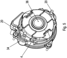
- the studs 20 are each arranged in one of the free spaces.
- the radial elevations 34 thus enable the formation of the free spaces, which not only function as a threading area for the tab areas of the friction plate 62, but also for receiving the anchor disk with the stud bolts 20, in particular with the two stud bolts 20.
- a nut 23 is screwed onto the stud bolts 20 at its end region facing the bearing flange 64 . This enables manual release.
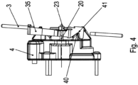
- a hand lever 3 which is connected to a release lever 35 is provided for this purpose. This engages either directly or by means of a linkage on the nut 23, so that turning the hand lever 3 enables the armature disk 2 to be displaced by engaging the nut 23, ie the brake is released by manual actuation. This is particularly useful in the de-energized case.
- the release lever 35 is reset by a reset spring element 30 .
- the release lever 35 rests on an elevation formed as a support or fulcrum 40 on the magnet body 4 so that it can be pivoted.
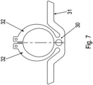
- the restoring spring element 30 has a spring arm area 31 and a clamping ring area 32 , the restoring spring element 30 being clipped with the clamping ring area 32 into an annular groove formed on the magnet body 4 like a locking ring.
- the restoring spring element 30 is thus introduced into the annular groove with a force fit and is thus held in a form-fitting manner, since the annular groove prevents the restoring spring element 30 from moving out.
- the restoring spring element 30 is supported by the annular groove on the magnet body 4 and presses the release lever 35 by means of its spring arm 31 so that it rests against the magnet body 4 in such a way that the brake remains undisturbed in its function.
- the release lever 35 When the manual release is actuated, the release lever 35 is deflected counter to the then elastically deflected spring arm 31 and pushes the nut 23 and thus the stud 20 away from the coil. Thus, the armature disk 2 is also removed from the coil 5 and the brake is released with it.
- FIG 4 is a side view showing the pivot bearing of the release lever 35 of the manual release and the limitation caused by the release lever 35 of the nut 23 screwed to a stud 20, with a restoring spring element 30 supported on the magnet body 4 pressing on the release lever 35.
- a linkage could also be fastened to the release lever, which would then limit the nut 23. In this case, however, more parts would then be necessary than in the case of the figures, in particular in figure 4 , version shown.
Landscapes
- Engineering & Computer Science (AREA)
- General Engineering & Computer Science (AREA)
- Mechanical Engineering (AREA)
- Physics & Mathematics (AREA)
- Electromagnetism (AREA)
- Power Engineering (AREA)
- Braking Arrangements (AREA)
Claims (12)
- Agencement de freinage à actionnement électromagnétique pour freiner un arbre, présentant :- un corps magnétique (4),- une bobine (5) reçue dans le corps magnétique (4),- un élément formant ressort (7),- un disque d'induit (2) solidaire en rotation du corps magnétique (4), mais mobile axialement,- un support de garniture de frein (1) solidaire en rotation de l'arbre, mais mobile axialement, et- une tôle de friction,dans lequel le disque d'induit (2) est disposé axialement entre la bobine (5) et le support de garniture de frein (1),dans lequel le support de garniture de frein (1) est disposé entre la tôle de friction et le support de garniture de frein (1),dans lequel la tôle de friction présente des zones formant pattes faisant saillie radialement vers l'extérieur, qui s'engagent dans une rainure annulaire du corps magnétique (4),en particulier dans lequel l'axe annulaire de la rainure annulaire est orienté axialement,la tôle de friction est reliée au corps magnétique (4) au moyen d'un verrouillage à baïonnette,dans lequel le disque d'induit (2), le support de garniture de frein (1) et la bobine (5) sont disposés dans la zone d'espace entourée par la tôle de friction ainsi que par le corps magnétique (4),dans lequel une tôle d'amortissement (60) est disposée entre le disque d'induit (2) et le corps magnétique (4), laquelle présente des surélévations pour amortir un impact respectif du disque d'induit (2) sur le corps magnétique (4),caractérisé en ce quesur le côté du corps magnétique (4) opposé à la tôle de friction est formée une surélévation réalisée sous la forme d'un élément d'appui ou d'un centre de rotation (40), qui sert de palier de rotation pour un levier de desserrage,dans lequel un élément formant ressort de rappel (30) supporté sur le corps magnétique (4) appuie sur le levier de desserrage,dans lequel le levier de desserrage limite la course axiale du disque d'induit (2).
- Agencement de freinage selon la revendication 1,
caractérisé en ce que
l'agencement de freinage est préassemblé. - Agencement de freinage selon au moins l'une des revendications précédentes,
caractérisé en ce quel'élément formant ressort (7) est supporté dans le corps magnétique (4) et appuie sur le disque d'induit (2),en particulier de telle sorte que, lorsque la bobine (5) est alimentée en courant, la force d'attraction magnétique générée par la bobine (5) surmonte la force élastique générée par l'élément formant ressort (7), de sorte que le disque d'induit (2) est attiré vers le corps magnétique (4). - Agencement de freinage selon au moins l'une des revendications précédentes,
caractérisé en cequ'un moyen de centrage, tel qu'un alésage de centrage ou une collerette de centrage, est formé sur le corps magnétique (4),en particulier dans lequel une bague d'étanchéité d'arbre (8) est montée sur le côté du corps magnétique (4) opposé à la tôle de friction pour assurer l'étanchéité du corps magnétique (4) par rapport à l'arbre. - Agencement de freinage selon au moins l'une des revendications précédentes,
caractérisé en cequ'un goujon fileté (20) est relié au disque d'induit (2), en particulier par vissage,dans lequel le goujon fileté (20) est monté dans le corps magnétique (4) de manière à pouvoir coulisser axialement et/ou au moyen d'un palier lisse, en particulier une douille, en particulier une douille en matière plastique,dans lequel le palier lisse est reçu dans un évidement, en particulier un alésage, du corps magnétique (4),en particulier dans lequel un écrou est relié au goujon fileté (20) au niveau de la zone d'extrémité du goujon fileté (20) opposée au disque d'induit (2). - Agencement de freinage selon au moins l'une des revendications précédentes,
caractérisé en ce que
le levier de desserrage limite la course axiale du disque d'induit (2) en limitant ou en poussant axialement un écrou qui est relié à un goujon fileté (20) qui est relié au disque d'induit (2). - Agencement de freinage selon au moins l'une des revendications précédentes,
caractérisé en ce quel'élément formant ressort de rappel (30) présente une zone formant bague de serrage reliée au corps magnétique (4) et une zone formant bras élastique,dans lequel la zone formant bras élastique appuie sur le levier de desserrage,en particulier dans lequel la zone formant bras élastique est déviée élastiquement en cas d'actionnement du levier de desserrage, en particulier donc de déviation du levier de desserrage. - Agencement de freinage selon au moins l'une des revendications précédentes,
caractérisé en ce que
la zone formant bague de serrage est encliquetée dans une rainure annulaire formée sur le corps magnétique (4), en particulier la zone formant bague de serrage présente une zone annulaire, une fente séparant la zone annulaire en deux parties, les deux parties étant maintenues précontraintes élastiquement dans la rainure annulaire, en particulier appuyant contre le fond de la rainure annulaire. - Agencement de freinage selon au moins l'une des revendications précédentes,
caractérisé en ce que
le goujon fileté (20) présente une première partie filetée et une deuxième partie filetée, une partie cylindrique étant formée axialement sur le goujon fileté (20) entre la première et la deuxième partie filetée. - Agencement de freinage selon au moins l'une des revendications précédentes,
caractérisé en ce queles goujons filetés (20) sont disposés à une plus grande distance radiale de l'axe d'arbre que le support de garniture,et/ou en ce que la plage de distance radiale couverte par les goujons filetés (20) est disposée radialement à l'extérieur de la plage de distance radiale couverte par le support de garniture et/ou au moins en chevauchement avec le support de garniture par une zone formant patte formée sur le disque de friction. - Moteur électrique doté d'un agencement de freinage selon au moins l'une des revendications précédentes,
caractérisé en ce quele moteur électrique présente une bride de palier dans laquelle est reçu un premier palier, dans lequel le moteur électrique présente une partie formant bride dans laquelle est reçu un deuxième palier,dans lequel l'arbre est monté au moyen du premier et du deuxième palier du moteur. - Moteur électrique selon la revendication précédente,
caractérisé en ce quela bride de palier est reliée au corps magnétique (4) et présente un moyen de centrage correspondant au moyen de centrage du corps magnétique (4), en particulier une collerette de centrage ou un alésage de centrage,
et/ou en ce quela tôle de friction est en contact avec la bride de palier, en particulier pour évacuer la chaleur de friction de l'agencement de freinage vers la bride de palier.
Applications Claiming Priority (2)
| Application Number | Priority Date | Filing Date | Title |
|---|---|---|---|
| DE102017000845.0A DE102017000845B4 (de) | 2017-01-31 | 2017-01-31 | Elektromagnetisch betätigbare Bremsanordnung zum Abbremsen einer Welle und Elektromotor mit einer solchen Bremsanordnung |
| PCT/EP2018/025009 WO2018141480A1 (fr) | 2017-01-31 | 2018-01-16 | Système de freinage à commande électromagnétique pour le freinage d'un arbre et moteur électrique équipé d'un tel système de freinage |
Publications (2)
| Publication Number | Publication Date |
|---|---|
| EP3577363A1 EP3577363A1 (fr) | 2019-12-11 |
| EP3577363B1 true EP3577363B1 (fr) | 2023-03-15 |
Family
ID=61094388
Family Applications (1)
| Application Number | Title | Priority Date | Filing Date |
|---|---|---|---|
| EP18702054.0A Active EP3577363B1 (fr) | 2017-01-31 | 2018-01-16 | Freinage electromechanique pour un axe, et electromoteur avec un tel freinage |
Country Status (3)
| Country | Link |
|---|---|
| EP (1) | EP3577363B1 (fr) |
| DE (1) | DE102017000845B4 (fr) |
| WO (1) | WO2018141480A1 (fr) |
Families Citing this family (19)
| Publication number | Priority date | Publication date | Assignee | Title |
|---|---|---|---|---|
| EP3640195A1 (fr) * | 2018-10-19 | 2020-04-22 | Otis Elevator Company | Frein d'ascenseur |
| DE102018009527A1 (de) | 2018-12-07 | 2020-06-10 | Wilo Se | Elektromotor mit Montageflansch |
| CN109787415B (zh) * | 2019-02-18 | 2023-08-18 | 安徽创新电磁离合器有限公司 | 一种伺服电机制动器低噪音运行结构 |
| CN110031194B (zh) * | 2019-03-18 | 2020-09-29 | 嘉兴威凯检测技术有限公司 | 一种晾衣架的测试装置 |
| CN110005732B (zh) * | 2019-04-03 | 2020-09-22 | 庆安集团有限公司 | 一种电磁制动器 |
| DE102019120043A1 (de) * | 2019-07-24 | 2021-01-28 | Konecranes Global Corp. | Elektromagnetische Bremse |
| DE102019120041A1 (de) * | 2019-07-24 | 2021-01-28 | Konecranes Global Corp. | Elektromagnetische Bremse |
| DE102019120042A1 (de) * | 2019-07-24 | 2021-01-28 | Konecranes Global Corp. | Elektromagnetische Bremse |
| CN116057817A (zh) | 2020-09-10 | 2023-05-02 | 索尤若驱动有限及两合公司 | 具有能电磁操纵的制动器的电机 |
| CN112762110A (zh) * | 2021-02-02 | 2021-05-07 | 北京理工大学 | 一种径向钳齿式制动器 |
| CN112984012B (zh) * | 2021-04-20 | 2021-07-27 | 成都瑞迪智驱科技股份有限公司 | 一种手自一体释放与自锁电磁制动系统 |
| DE102022001331A1 (de) * | 2021-05-12 | 2022-11-17 | Sew-Eurodrive Gmbh & Co Kg | Bremsanordnung, aufweisend eine Bremse, einen Adapter und ein Getriebe |
| CN117859256A (zh) | 2021-09-14 | 2024-04-09 | 索尤若驱动有限及两合公司 | 具有制动装置的电机 |
| CN113904494A (zh) * | 2021-09-30 | 2022-01-07 | 达闼机器人有限公司 | 一种断电保护电机与执行器 |
| WO2023110382A1 (fr) | 2021-12-13 | 2023-06-22 | Sew-Eurodrive Gmbh & Co. Kg | Moteur électrique équipé d'un frein à actionnement électromagnétique |
| CN115076259A (zh) * | 2022-07-07 | 2022-09-20 | 成都超德创科技有限公司 | 一种转子结构的电磁制动器 |
| CN116277128B (zh) * | 2022-10-08 | 2025-12-19 | 深圳市越疆科技股份有限公司 | 机械臂及其关节模组 |
| WO2026046615A1 (fr) * | 2024-08-26 | 2026-03-05 | Sew-Eurodrive Gmbh & Co Kg | Procédé de fabrication d'un système de freinage, système de freinage et moteur électrique équipé d'un système de freinage |
| CN119483055B (zh) * | 2025-01-15 | 2025-04-11 | 天津普友机电设备股份有限公司 | 一种井用单电缆引出的双出轴水下电机 |
Family Cites Families (10)
| Publication number | Priority date | Publication date | Assignee | Title |
|---|---|---|---|---|
| DE1914395U (de) | 1963-05-13 | 1965-04-22 | Pintsch Bamag Ag | Einrichtung zur notlueftung elektromagnetischer scheiben-federbremsen. |
| US6459182B1 (en) | 1998-05-14 | 2002-10-01 | Sew-Eurodrive Gmbh | Electric motor with brake |
| EP0957565B1 (fr) | 1998-05-14 | 2003-09-17 | Sew-Eurodrive GmbH & Co. KG | Moteur électrique avec frein |
| DE102007028688A1 (de) | 2007-06-21 | 2008-12-24 | Jungheinrich Aktiengesellschaft | Automatische Federspeicherbremse für Flurförderzeug (FFZ) |
| DE102013005239B4 (de) | 2012-11-27 | 2015-03-12 | Sew-Eurodrive Gmbh & Co Kg | Bremsanordnung und Elektromotor |
| DE102013001899B4 (de) * | 2013-02-05 | 2022-09-08 | Sew-Eurodrive Gmbh & Co Kg | Bremsanordnung |
| DE102013016999B4 (de) * | 2013-10-15 | 2021-05-27 | Sew-Eurodrive Gmbh & Co Kg | Bremsanordnung und Elektromotor |
| DE102013020524B4 (de) * | 2013-12-11 | 2021-09-02 | Sew-Eurodrive Gmbh & Co Kg | Elektromagnetisch betätigbare Bremsanordnung und Elektromotor mit einer Bremsanordnung |
| DE102014018485B3 (de) * | 2014-12-16 | 2015-09-17 | Sew-Eurodrive Gmbh & Co Kg | Eletromagnetisch betätigbare Bremsvorrichtung |
| DE102015001647B4 (de) * | 2015-02-12 | 2025-10-23 | Sew-Eurodrive Gmbh & Co Kg | Bremsanordnung |
-
2017
- 2017-01-31 DE DE102017000845.0A patent/DE102017000845B4/de active Active
-
2018
- 2018-01-16 EP EP18702054.0A patent/EP3577363B1/fr active Active
- 2018-01-16 WO PCT/EP2018/025009 patent/WO2018141480A1/fr not_active Ceased
Also Published As
| Publication number | Publication date |
|---|---|
| DE102017000845A1 (de) | 2018-08-02 |
| WO2018141480A1 (fr) | 2018-08-09 |
| EP3577363A1 (fr) | 2019-12-11 |
| DE102017000845B4 (de) | 2022-06-02 |
Similar Documents
| Publication | Publication Date | Title |
|---|---|---|
| EP3577363B1 (fr) | Freinage electromechanique pour un axe, et electromoteur avec un tel freinage | |
| EP2926020B1 (fr) | Dispositif de freinage et moteur électrique | |
| DE102012019415A1 (de) | Elektromotor, insbesondere mit einer redundanten Bremsanordnung | |
| DE102014010918B4 (de) | Elektromotor, aufweisend einen Stator und einen Rotor, und Verfahren zum Herstellen eines Elektromotors | |
| EP3080474B1 (fr) | Système de freinage à commande électromagnétique et moteur électrique muni d'un système de freinage | |
| DE102013001899B4 (de) | Bremsanordnung | |
| DE102014012348B4 (de) | Elektromotor, aufweisend einen Stator und einen Rotor, und Verfahren zum Herstellen einer elektromotorisch angetriebenen Maschine | |
| EP2962008B1 (fr) | Frein à ressort à actionnement électromagnétique | |
| DE102018006725A1 (de) | Elektromagnetisch betätigbare Bremsanordnung und Verfahren zur Inbetriebnahme oder Wartung einer elektromagnetisch betätigbaren Bremsanordnung | |
| EP2901037B1 (fr) | Système de frein et moteur électrique équipé d'un système de frein | |
| DE102015001647A1 (de) | Bremsanordnung | |
| DE102022000375A1 (de) | Elekromotor mit einer elektromagnetisch betätigbaren Bremse | |
| DE102020004262A1 (de) | Bremsanordnung zum Abbremsen einer um eine Drehachse drehbar gelagerten Welle | |
| EP2786036B1 (fr) | Système de freinage | |
| DE102016012643B4 (de) | Elektromagnetisch betätigbare Bremsanordnung | |
| EP3788271A1 (fr) | Moteur électrique muni d'un accouplement entre l'arbre de rotor et l'arbre d'un capteur d'angle | |
| WO2024170199A1 (fr) | Frein à actionnement électromagnétique et moteur électrique équipé d'un frein à actionnement électromagnétique | |
| EP4684465A1 (fr) | Frein à actionnement électromagnétique et moteur électrique équipé d'un frein à actionnement électromagnétique | |
| EP4430318A1 (fr) | Dispositif de freinage comportant en particulier un arbre à freiner et une partie boîtier | |
| DE102017009332A1 (de) | Elektromagnetisch betätigbare Bremsanordnung und Verfahren zur Inbetriebnahme oder Wartung einer elektromagnetisch betätigbaren Bremsanordnung | |
| DE102015212227A1 (de) | Elektromagnetische Reibungsbremse |
Legal Events
| Date | Code | Title | Description |
|---|---|---|---|
| STAA | Information on the status of an ep patent application or granted ep patent |
Free format text: STATUS: UNKNOWN |
|
| STAA | Information on the status of an ep patent application or granted ep patent |
Free format text: STATUS: THE INTERNATIONAL PUBLICATION HAS BEEN MADE |
|
| PUAI | Public reference made under article 153(3) epc to a published international application that has entered the european phase |
Free format text: ORIGINAL CODE: 0009012 |
|
| STAA | Information on the status of an ep patent application or granted ep patent |
Free format text: STATUS: REQUEST FOR EXAMINATION WAS MADE |
|
| 17P | Request for examination filed |
Effective date: 20190902 |
|
| AK | Designated contracting states |
Kind code of ref document: A1 Designated state(s): AL AT BE BG CH CY CZ DE DK EE ES FI FR GB GR HR HU IE IS IT LI LT LU LV MC MK MT NL NO PL PT RO RS SE SI SK SM TR |
|
| AX | Request for extension of the european patent |
Extension state: BA ME |
|
| DAV | Request for validation of the european patent (deleted) | ||
| DAX | Request for extension of the european patent (deleted) | ||
| GRAP | Despatch of communication of intention to grant a patent |
Free format text: ORIGINAL CODE: EPIDOSNIGR1 |
|
| STAA | Information on the status of an ep patent application or granted ep patent |
Free format text: STATUS: GRANT OF PATENT IS INTENDED |
|
| INTG | Intention to grant announced |
Effective date: 20221031 |
|
| GRAS | Grant fee paid |
Free format text: ORIGINAL CODE: EPIDOSNIGR3 |
|
| GRAA | (expected) grant |
Free format text: ORIGINAL CODE: 0009210 |
|
| STAA | Information on the status of an ep patent application or granted ep patent |
Free format text: STATUS: THE PATENT HAS BEEN GRANTED |
|
| AK | Designated contracting states |
Kind code of ref document: B1 Designated state(s): AL AT BE BG CH CY CZ DE DK EE ES FI FR GB GR HR HU IE IS IT LI LT LU LV MC MK MT NL NO PL PT RO RS SE SI SK SM TR |
|
| REG | Reference to a national code |
Ref country code: CH Ref legal event code: EP Ref country code: GB Ref legal event code: FG4D Free format text: NOT ENGLISH |
|
| REG | Reference to a national code |
Ref country code: DE Ref legal event code: R096 Ref document number: 502018011768 Country of ref document: DE |
|
| REG | Reference to a national code |
Ref country code: IE Ref legal event code: FG4D Free format text: LANGUAGE OF EP DOCUMENT: GERMAN |
|
| REG | Reference to a national code |
Ref country code: AT Ref legal event code: REF Ref document number: 1554169 Country of ref document: AT Kind code of ref document: T Effective date: 20230415 |
|
| REG | Reference to a national code |
Ref country code: LT Ref legal event code: MG9D |
|
| REG | Reference to a national code |
Ref country code: NL Ref legal event code: MP Effective date: 20230315 |
|
| PG25 | Lapsed in a contracting state [announced via postgrant information from national office to epo] |
Ref country code: RS Free format text: LAPSE BECAUSE OF FAILURE TO SUBMIT A TRANSLATION OF THE DESCRIPTION OR TO PAY THE FEE WITHIN THE PRESCRIBED TIME-LIMIT Effective date: 20230315 Ref country code: NO Free format text: LAPSE BECAUSE OF FAILURE TO SUBMIT A TRANSLATION OF THE DESCRIPTION OR TO PAY THE FEE WITHIN THE PRESCRIBED TIME-LIMIT Effective date: 20230615 Ref country code: LV Free format text: LAPSE BECAUSE OF FAILURE TO SUBMIT A TRANSLATION OF THE DESCRIPTION OR TO PAY THE FEE WITHIN THE PRESCRIBED TIME-LIMIT Effective date: 20230315 Ref country code: LT Free format text: LAPSE BECAUSE OF FAILURE TO SUBMIT A TRANSLATION OF THE DESCRIPTION OR TO PAY THE FEE WITHIN THE PRESCRIBED TIME-LIMIT Effective date: 20230315 Ref country code: HR Free format text: LAPSE BECAUSE OF FAILURE TO SUBMIT A TRANSLATION OF THE DESCRIPTION OR TO PAY THE FEE WITHIN THE PRESCRIBED TIME-LIMIT Effective date: 20230315 |
|
| PG25 | Lapsed in a contracting state [announced via postgrant information from national office to epo] |
Ref country code: SE Free format text: LAPSE BECAUSE OF FAILURE TO SUBMIT A TRANSLATION OF THE DESCRIPTION OR TO PAY THE FEE WITHIN THE PRESCRIBED TIME-LIMIT Effective date: 20230315 Ref country code: NL Free format text: LAPSE BECAUSE OF FAILURE TO SUBMIT A TRANSLATION OF THE DESCRIPTION OR TO PAY THE FEE WITHIN THE PRESCRIBED TIME-LIMIT Effective date: 20230315 Ref country code: GR Free format text: LAPSE BECAUSE OF FAILURE TO SUBMIT A TRANSLATION OF THE DESCRIPTION OR TO PAY THE FEE WITHIN THE PRESCRIBED TIME-LIMIT Effective date: 20230616 Ref country code: FI Free format text: LAPSE BECAUSE OF FAILURE TO SUBMIT A TRANSLATION OF THE DESCRIPTION OR TO PAY THE FEE WITHIN THE PRESCRIBED TIME-LIMIT Effective date: 20230315 |
|
| PG25 | Lapsed in a contracting state [announced via postgrant information from national office to epo] |
Ref country code: SM Free format text: LAPSE BECAUSE OF FAILURE TO SUBMIT A TRANSLATION OF THE DESCRIPTION OR TO PAY THE FEE WITHIN THE PRESCRIBED TIME-LIMIT Effective date: 20230315 Ref country code: RO Free format text: LAPSE BECAUSE OF FAILURE TO SUBMIT A TRANSLATION OF THE DESCRIPTION OR TO PAY THE FEE WITHIN THE PRESCRIBED TIME-LIMIT Effective date: 20230315 Ref country code: PT Free format text: LAPSE BECAUSE OF FAILURE TO SUBMIT A TRANSLATION OF THE DESCRIPTION OR TO PAY THE FEE WITHIN THE PRESCRIBED TIME-LIMIT Effective date: 20230717 Ref country code: ES Free format text: LAPSE BECAUSE OF FAILURE TO SUBMIT A TRANSLATION OF THE DESCRIPTION OR TO PAY THE FEE WITHIN THE PRESCRIBED TIME-LIMIT Effective date: 20230315 Ref country code: EE Free format text: LAPSE BECAUSE OF FAILURE TO SUBMIT A TRANSLATION OF THE DESCRIPTION OR TO PAY THE FEE WITHIN THE PRESCRIBED TIME-LIMIT Effective date: 20230315 Ref country code: CZ Free format text: LAPSE BECAUSE OF FAILURE TO SUBMIT A TRANSLATION OF THE DESCRIPTION OR TO PAY THE FEE WITHIN THE PRESCRIBED TIME-LIMIT Effective date: 20230315 |
|
| PG25 | Lapsed in a contracting state [announced via postgrant information from national office to epo] |
Ref country code: SK Free format text: LAPSE BECAUSE OF FAILURE TO SUBMIT A TRANSLATION OF THE DESCRIPTION OR TO PAY THE FEE WITHIN THE PRESCRIBED TIME-LIMIT Effective date: 20230315 Ref country code: PL Free format text: LAPSE BECAUSE OF FAILURE TO SUBMIT A TRANSLATION OF THE DESCRIPTION OR TO PAY THE FEE WITHIN THE PRESCRIBED TIME-LIMIT Effective date: 20230315 Ref country code: IS Free format text: LAPSE BECAUSE OF FAILURE TO SUBMIT A TRANSLATION OF THE DESCRIPTION OR TO PAY THE FEE WITHIN THE PRESCRIBED TIME-LIMIT Effective date: 20230715 |
|
| REG | Reference to a national code |
Ref country code: DE Ref legal event code: R097 Ref document number: 502018011768 Country of ref document: DE |
|
| PLBE | No opposition filed within time limit |
Free format text: ORIGINAL CODE: 0009261 |
|
| STAA | Information on the status of an ep patent application or granted ep patent |
Free format text: STATUS: NO OPPOSITION FILED WITHIN TIME LIMIT |
|
| PG25 | Lapsed in a contracting state [announced via postgrant information from national office to epo] |
Ref country code: SI Free format text: LAPSE BECAUSE OF FAILURE TO SUBMIT A TRANSLATION OF THE DESCRIPTION OR TO PAY THE FEE WITHIN THE PRESCRIBED TIME-LIMIT Effective date: 20230315 Ref country code: DK Free format text: LAPSE BECAUSE OF FAILURE TO SUBMIT A TRANSLATION OF THE DESCRIPTION OR TO PAY THE FEE WITHIN THE PRESCRIBED TIME-LIMIT Effective date: 20230315 |
|
| 26N | No opposition filed |
Effective date: 20231218 |
|
| PG25 | Lapsed in a contracting state [announced via postgrant information from national office to epo] |
Ref country code: MC Free format text: LAPSE BECAUSE OF FAILURE TO SUBMIT A TRANSLATION OF THE DESCRIPTION OR TO PAY THE FEE WITHIN THE PRESCRIBED TIME-LIMIT Effective date: 20230315 |
|
| PG25 | Lapsed in a contracting state [announced via postgrant information from national office to epo] |
Ref country code: MC Free format text: LAPSE BECAUSE OF FAILURE TO SUBMIT A TRANSLATION OF THE DESCRIPTION OR TO PAY THE FEE WITHIN THE PRESCRIBED TIME-LIMIT Effective date: 20230315 |
|
| REG | Reference to a national code |
Ref country code: CH Ref legal event code: PL |
|
| PG25 | Lapsed in a contracting state [announced via postgrant information from national office to epo] |
Ref country code: LU Free format text: LAPSE BECAUSE OF NON-PAYMENT OF DUE FEES Effective date: 20240116 |
|
| GBPC | Gb: european patent ceased through non-payment of renewal fee |
Effective date: 20240116 |
|
| PG25 | Lapsed in a contracting state [announced via postgrant information from national office to epo] |
Ref country code: LU Free format text: LAPSE BECAUSE OF NON-PAYMENT OF DUE FEES Effective date: 20240116 |
|
| PG25 | Lapsed in a contracting state [announced via postgrant information from national office to epo] |
Ref country code: GB Free format text: LAPSE BECAUSE OF NON-PAYMENT OF DUE FEES Effective date: 20240116 |
|
| PG25 | Lapsed in a contracting state [announced via postgrant information from national office to epo] |
Ref country code: BE Free format text: LAPSE BECAUSE OF NON-PAYMENT OF DUE FEES Effective date: 20240131 |
|
| PG25 | Lapsed in a contracting state [announced via postgrant information from national office to epo] |
Ref country code: CH Free format text: LAPSE BECAUSE OF NON-PAYMENT OF DUE FEES Effective date: 20240131 |
|
| PG25 | Lapsed in a contracting state [announced via postgrant information from national office to epo] |
Ref country code: GB Free format text: LAPSE BECAUSE OF NON-PAYMENT OF DUE FEES Effective date: 20240116 Ref country code: CH Free format text: LAPSE BECAUSE OF NON-PAYMENT OF DUE FEES Effective date: 20240131 Ref country code: BE Free format text: LAPSE BECAUSE OF NON-PAYMENT OF DUE FEES Effective date: 20240131 |
|
| REG | Reference to a national code |
Ref country code: BE Ref legal event code: MM Effective date: 20240131 |
|
| PG25 | Lapsed in a contracting state [announced via postgrant information from national office to epo] |
Ref country code: BG Free format text: LAPSE BECAUSE OF FAILURE TO SUBMIT A TRANSLATION OF THE DESCRIPTION OR TO PAY THE FEE WITHIN THE PRESCRIBED TIME-LIMIT Effective date: 20230315 |
|
| PG25 | Lapsed in a contracting state [announced via postgrant information from national office to epo] |
Ref country code: BG Free format text: LAPSE BECAUSE OF FAILURE TO SUBMIT A TRANSLATION OF THE DESCRIPTION OR TO PAY THE FEE WITHIN THE PRESCRIBED TIME-LIMIT Effective date: 20230315 |
|
| PG25 | Lapsed in a contracting state [announced via postgrant information from national office to epo] |
Ref country code: IE Free format text: LAPSE BECAUSE OF NON-PAYMENT OF DUE FEES Effective date: 20240116 |
|
| PG25 | Lapsed in a contracting state [announced via postgrant information from national office to epo] |
Ref country code: IE Free format text: LAPSE BECAUSE OF NON-PAYMENT OF DUE FEES Effective date: 20240116 |
|
| REG | Reference to a national code |
Ref country code: AT Ref legal event code: MM01 Ref document number: 1554169 Country of ref document: AT Kind code of ref document: T Effective date: 20240116 |
|
| PG25 | Lapsed in a contracting state [announced via postgrant information from national office to epo] |
Ref country code: AT Free format text: LAPSE BECAUSE OF NON-PAYMENT OF DUE FEES Effective date: 20240116 |
|
| PG25 | Lapsed in a contracting state [announced via postgrant information from national office to epo] |
Ref country code: CY Free format text: LAPSE BECAUSE OF FAILURE TO SUBMIT A TRANSLATION OF THE DESCRIPTION OR TO PAY THE FEE WITHIN THE PRESCRIBED TIME-LIMIT; INVALID AB INITIO Effective date: 20180116 |
|
| PG25 | Lapsed in a contracting state [announced via postgrant information from national office to epo] |
Ref country code: HU Free format text: LAPSE BECAUSE OF FAILURE TO SUBMIT A TRANSLATION OF THE DESCRIPTION OR TO PAY THE FEE WITHIN THE PRESCRIBED TIME-LIMIT; INVALID AB INITIO Effective date: 20180116 |
|
| PG25 | Lapsed in a contracting state [announced via postgrant information from national office to epo] |
Ref country code: TR Free format text: LAPSE BECAUSE OF FAILURE TO SUBMIT A TRANSLATION OF THE DESCRIPTION OR TO PAY THE FEE WITHIN THE PRESCRIBED TIME-LIMIT Effective date: 20230315 |
|
| PGFP | Annual fee paid to national office [announced via postgrant information from national office to epo] |
Ref country code: FR Payment date: 20251208 Year of fee payment: 9 |
|
| PGFP | Annual fee paid to national office [announced via postgrant information from national office to epo] |
Ref country code: DE Payment date: 20260131 Year of fee payment: 9 |
|
| PGFP | Annual fee paid to national office [announced via postgrant information from national office to epo] |
Ref country code: IT Payment date: 20260108 Year of fee payment: 9 |