EP3578320B1 - Configurer un endroit dangereux surveillé par un capteur tridimensionnel - Google Patents
Configurer un endroit dangereux surveillé par un capteur tridimensionnel Download PDFInfo
- Publication number
- EP3578320B1 EP3578320B1 EP18176458.0A EP18176458A EP3578320B1 EP 3578320 B1 EP3578320 B1 EP 3578320B1 EP 18176458 A EP18176458 A EP 18176458A EP 3578320 B1 EP3578320 B1 EP 3578320B1
- Authority
- EP
- European Patent Office
- Prior art keywords
- sensor
- hazardous zone
- danger
- machine
- hazardous
- Prior art date
- Legal status (The legal status is an assumption and is not a legal conclusion. Google has not performed a legal analysis and makes no representation as to the accuracy of the status listed.)
- Active
Links
Images


Classifications
-
- B—PERFORMING OPERATIONS; TRANSPORTING
- B25—HAND TOOLS; PORTABLE POWER-DRIVEN TOOLS; MANIPULATORS
- B25J—MANIPULATORS; CHAMBERS PROVIDED WITH MANIPULATION DEVICES
- B25J9/00—Program-controlled manipulators
- B25J9/16—Program controls
- B25J9/1674—Program controls characterised by safety, monitoring, diagnostic
- B25J9/1676—Avoiding collision or forbidden zones
-
- G—PHYSICS
- G05—CONTROLLING; REGULATING
- G05B—CONTROL OR REGULATING SYSTEMS IN GENERAL; FUNCTIONAL ELEMENTS OF SUCH SYSTEMS; MONITORING OR TESTING ARRANGEMENTS FOR SUCH SYSTEMS OR ELEMENTS
- G05B19/00—Program-control systems
- G05B19/02—Program-control systems electric
- G05B19/18—Numerical control [NC], i.e. automatically operating machines, in particular machine tools, e.g. in a manufacturing environment, so as to execute positioning, movement or co-ordinated operations by means of program data in numerical form
- G05B19/406—Numerical control [NC], i.e. automatically operating machines, in particular machine tools, e.g. in a manufacturing environment, so as to execute positioning, movement or co-ordinated operations by means of program data in numerical form characterised by monitoring or safety
-
- G—PHYSICS
- G05—CONTROLLING; REGULATING
- G05B—CONTROL OR REGULATING SYSTEMS IN GENERAL; FUNCTIONAL ELEMENTS OF SUCH SYSTEMS; MONITORING OR TESTING ARRANGEMENTS FOR SUCH SYSTEMS OR ELEMENTS
- G05B19/00—Program-control systems
- G05B19/02—Program-control systems electric
- G05B19/18—Numerical control [NC], i.e. automatically operating machines, in particular machine tools, e.g. in a manufacturing environment, so as to execute positioning, movement or co-ordinated operations by means of program data in numerical form
- G05B19/406—Numerical control [NC], i.e. automatically operating machines, in particular machine tools, e.g. in a manufacturing environment, so as to execute positioning, movement or co-ordinated operations by means of program data in numerical form characterised by monitoring or safety
- G05B19/4061—Avoiding collision or forbidden zones
-
- G—PHYSICS
- G06—COMPUTING OR CALCULATING; COUNTING
- G06T—IMAGE DATA PROCESSING OR GENERATION, IN GENERAL
- G06T7/00—Image analysis
- G06T7/50—Depth or shape recovery
- G06T7/521—Depth or shape recovery from laser ranging, e.g. using interferometry; from the projection of structured light
-
- G—PHYSICS
- G06—COMPUTING OR CALCULATING; COUNTING
- G06T—IMAGE DATA PROCESSING OR GENERATION, IN GENERAL
- G06T7/00—Image analysis
- G06T7/50—Depth or shape recovery
- G06T7/55—Depth or shape recovery from multiple images
- G06T7/593—Depth or shape recovery from multiple images from stereo images
-
- G—PHYSICS
- G06—COMPUTING OR CALCULATING; COUNTING
- G06T—IMAGE DATA PROCESSING OR GENERATION, IN GENERAL
- G06T7/00—Image analysis
- G06T7/80—Analysis of captured images to determine intrinsic or extrinsic camera parameters, i.e. camera calibration
-
- H—ELECTRICITY
- H04—ELECTRIC COMMUNICATION TECHNIQUE
- H04N—PICTORIAL COMMUNICATION, e.g. TELEVISION
- H04N13/00—Stereoscopic video systems; Multi-view video systems; Details thereof
- H04N13/20—Image signal generators
- H04N13/204—Image signal generators using stereoscopic image cameras
- H04N13/239—Image signal generators using stereoscopic image cameras using two two-dimensional [2D] image sensors having a relative position equal to or related to the interocular distance
-
- H—ELECTRICITY
- H04—ELECTRIC COMMUNICATION TECHNIQUE
- H04N—PICTORIAL COMMUNICATION, e.g. TELEVISION
- H04N7/00—Television systems
- H04N7/18—Closed-circuit television [CCTV] systems, i.e. systems in which the video signal is not broadcast
- H04N7/181—Closed-circuit television [CCTV] systems, i.e. systems in which the video signal is not broadcast for receiving images from a plurality of remote sources
-
- G—PHYSICS
- G05—CONTROLLING; REGULATING
- G05B—CONTROL OR REGULATING SYSTEMS IN GENERAL; FUNCTIONAL ELEMENTS OF SUCH SYSTEMS; MONITORING OR TESTING ARRANGEMENTS FOR SUCH SYSTEMS OR ELEMENTS
- G05B2219/00—Program-control systems
- G05B2219/30—Nc systems
- G05B2219/37—Measurements
- G05B2219/37631—Means detecting object in forbidden zone
-
- G—PHYSICS
- G05—CONTROLLING; REGULATING
- G05B—CONTROL OR REGULATING SYSTEMS IN GENERAL; FUNCTIONAL ELEMENTS OF SUCH SYSTEMS; MONITORING OR TESTING ARRANGEMENTS FOR SUCH SYSTEMS OR ELEMENTS
- G05B2219/00—Program-control systems
- G05B2219/30—Nc systems
- G05B2219/50—Machine tool, machine tool null till machine tool work handling
- G05B2219/50193—Safety in general
-
- G—PHYSICS
- G06—COMPUTING OR CALCULATING; COUNTING
- G06T—IMAGE DATA PROCESSING OR GENERATION, IN GENERAL
- G06T2207/00—Indexing scheme for image analysis or image enhancement
- G06T2207/30—Subject of image; Context of image processing
- G06T2207/30232—Surveillance
Definitions
- the invention relates to a method and a device for configuring a hazard point to be monitored by a 3D sensor according to the preamble of claims 1 and 14, respectively.
- the primary goal of safety technology is to protect people from sources of danger, such as those presented by machines in an industrial environment.
- the machine is monitored with the aid of sensors, and if there is a situation in which a person threatens to get dangerously close to the machine, a suitable safety measure is taken.
- 3D sensors are used for monitoring. This initially includes 3D cameras in different technologies, for example stereoscopy, triangulation, time of flight or evaluation of the disturbance of passive two-dimensional patterns or of projected lighting patterns. In contrast to a conventional two-dimensional camera, such 3D sensors record images that contain a distance value in their pixels. This depth-resolved or three-dimensional image data is also referred to as a depth map. Also known are laser scanners which scan in two or all three directions and which likewise acquire three-dimensional image data via the respective scanning angle and the measured distance. The higher equipment and evaluation effort for generating three-dimensional image data compared to two-dimensional image acquisition is justified in many applications by the additional information.
- Sensors used in safety technology or for personal protection must work particularly reliably and therefore meet high safety requirements, for example the EN13849 standard for machine safety and the Device standard IEC61496 or EN61496 for electro-sensitive protective equipment (ESPE).
- a number of measures must be taken to meet these safety standards, such as safe electronic evaluation through redundant, diverse electronics, function monitoring or, in particular, monitoring of the contamination of optical components.
- it is typically required that an object with a certain minimum size or certain minimum dimensions is reliably detected. This property is called detection capability.
- the current protection concept provides that protective fields are configured that are not allowed to be entered by the operating personnel while the machine is in operation. If the sensor detects an impermissible protective field interference, for example an operator's leg, it triggers a safety-related stop of the machine.
- speed and separation monitoring An evaluation of objects and machines with regard to speed and mutual distance is referred to as "speed and separation monitoring" in the robot standards mentioned.
- the distance to the machine itself is expediently not calculated. That would be too complex and dynamic, and there should also be a sufficient safety distance to future machine positions. It therefore makes sense to configure a hazard area that surrounds the machine.
- the setter is not supported in determining whether the configuration is safe.
- the safety function can suffer because objects cannot be seen from the perspective of the monitoring sensor or suddenly disappear in the danger zone.
- the setter is left with the responsibility to ensure that a configuration offers the desired level of security.
- the DE10 2005 063 217 B4 discloses a method for configuring protective fields for a stereo camera. For this purpose, a three-dimensional image of the spatial area is recorded and displayed, and volumes are defined therein in a kind of CAD environment, which are to be monitored as protective fields. However, there is then no automatic check as to whether the sensor can actually detect these protective fields. In addition, there are different requirements for the configuration, whether it should be recognized when an object has entered a room volume such as a protective field, or whether the distance to a room volume such as a danger point is to be determined.
- danger area In the DE 10 2012 007 242 A1 a danger area around a robot is monitored with a detection system.
- the term danger area actually refers to a protective field, because it is allowed to approach the danger area at will, but not to enter it. There is no configuration of the danger area, rather it adapts dynamically to the movements of the robot or a person in its environment. It is not automatically checked to what extent the danger area can be detected by the detection system.
- the EP 2 023 160 B1 discloses a three-dimensional space monitoring with a configuration mode for determining the protective fields on the basis of visual markers. Movement sequences of a source of danger are monitored and a protective field is automatically configured from this. As a result, this is also about protective fields, not danger spots, and there is no automatic check as to whether the protective fields can actually be monitored.
- the U.S. 6,829,371 B1 deals with an automatic setup of an optical safety curtain based on a boundary pattern for a protective field in the scenery. Apart from the fact that it is again about protective fields and not danger spots, the three-dimensional situation is not adequately assessed due to such two-dimensional boundaries.
- the EP 3 112 900 A1 discloses a security system which estimates the volume occupied by a detected object and uses it as the basis for a risk assessment. This affects the object to be detected, i.e. the person, and not the machine to be monitored.
- the US 2016/0207198 A1 presents a method for verifying security areas.
- the security areas are displayed in an augmented reality display on a mobile device. This can help the setter to assess the safety areas, but otherwise leaves the responsibility entirely with him. In addition, there is no explanation of the extent to which the safety areas can be monitored by a sensor.
- the EP 2 275 990 B1 deals with gaps in the depth map.
- a safety-related shutdown command is issued if there are gaps or contiguous pixel areas without gaps that are larger than the smallest object to be detected, where the worst case assumption is that the size of a gap is projected onto the edge. This is an additional safety measure, but it has nothing to do with the configuration of protective fields or danger zones.
- the EP 3 200 122 A1 discloses a 3D sensor with reliable detection of objects, in which the depth map is evaluated with a fine and a coarse detection capability. Finely recorded objects within the surroundings of a roughly recorded object are added to it, isolated finely recorded objects are ignored as a disturbance. This makes it possible to filter out certain small objects downstream as not safety-relevant, but also has no direct connection with the configuration of protective fields or danger spots.
- the EP 3 142 088 A1 discloses a method for setting multiple sub-areas of a desired protection area.
- a specified protective field is automatically divided up so that it is continuously monitored by several laser scanners from different perspectives.
- a danger point protects at least one machine and is monitored by the 3D sensor so that nobody is injured by the machine.
- the machine is preferably at least partially in the danger zone.
- a danger point is a volume determined by its outer surfaces, i.e. a 3D spatial area. Hazardous locations can also be composed of several overlapping or disjoint volumes.
- the configuration according to the invention defines the outer surfaces, preferably by creating a data record which describes the configured hazard point and which the 3D sensor or a higher-level system uses for monitoring.
- the outer surfaces are crucial because it is monitored during operation whether a person is approaching the machine dangerously, and this depends on the limit area.
- a 3D body can still be configured directly, which implies the definition of its outer surfaces. In particular, it is about the lateral side surfaces, which prevent crawling under and reaching over through adequate dimensioning.
- the 3D sensor is preferably mounted in a bird's eye view, without actually restricting the invention to this.
- the invention is based on the basic idea that the configuration ensures that the hazard point is suitable for safe monitoring. For this purpose, it is checked whether the outer surfaces can be seen by at least one 3D sensor. All outer surfaces can be checked, but preferably only a subset of them, for example the lateral side surfaces.
- monitored exterior areas can be defined as a subset of the exterior areas, be it by automation or user input, and the monitored exterior areas are those that are checked for visibility. Other external areas are, for example, mechanically secured and are therefore not monitored external areas.
- Visible means an unobstructed view in the sense of a full-area, direct monitoring option.
- an outer surface that is rearward from the perspective of the 3D sensor can in a certain sense also be observed through the danger point, but that is precisely not visible in the sense of the invention because the machine obstructs the view in a very unpredictable manner. It is therefore by no means sufficient if an external surface is somehow in the field of vision.
- the 3-D sensor or a combination of several 3-D sensors, which complement each other in the field of vision and / or perspective, can therefore reliably perform its task with hazard areas configured according to the invention.
- the invention has the advantage that with the danger spots configured in this way, security problems due to covering or shading are avoided from the outset.
- the setter is automatically supported and cannot configure any dangerous areas that are not permitted in this sense or at least receives a clear indication of possible safety problems.
- there remains a big one Flexibility of the configurable danger zones is guaranteed. This enables danger spots that are close to the actual danger, in which the availability of the system remains high and distances from objects are not too greatly underestimated.
- the method is also suitable for several danger points to protect complex machines and systems and / or several 3D sensors that complement each other
- the 3D sensor is preferably a 3D camera that can initially use any known technology, such as a light transit time principle with direct transit time measurement of light signals or phase measurement or a distance estimate from brightness or focus positions (DFF, Depth from Focus, DFD, Depth from Defocus).
- the 3D camera particularly preferably uses a triangulation principle in which two camera images from a moving camera or a stereo camera are correlated with one another, or alternatively an illumination pattern is correlated with a camera image in order to estimate disparities and determine distances from them.
- a laser scanner is also a 3D sensor because it generates 3D point clouds that are limited to one scanning plane in a classic laser scanner. By scanning moved in elevation or by several scanning beams offset in elevation, this restriction does not apply to a laser scanner. Hybrid arrangements with different 3D sensors or other sensors, such as a light grid, are also conceivable.
- At least one polygon course is preferably specified on a base area, in particular a closed polygon course, and a prism with perpendicular outer surfaces is generated therefrom.
- the specification of the polygon on the base is only a linguistic simplification, since the polygon is the same for a prism with vertical side surfaces at every height.
- a good compromise is found using a polygon or a prism that can be automatically generated from it, which at the same time allows flexible, sufficiently complex configuration options for danger spots and is much more controllable in terms of safety than any 3D volume. For the fitter, too, such danger spots described by prisms with vertical side surfaces are easier to understand and test.
- the prism is preferably not a cuboid and / or not a triangular column. It is true that such simple danger spots should be expressly configurable and by no means prohibited. It is only about an optional restricted understanding of the concept of a polygon and the prism defined by it, which actually makes use of the more flexible and complex design options power. Hazardous areas can be composed of several prisms, which are specified via several polygonal lines.
- An outer surface can be viewed by a 3D sensor if the 3D sensor is arranged on the other side of the danger point with respect to the plane in which the outer surface lies. This is an advantageous and easily verifiable condition for when an outer surface can be viewed. It is sufficient if a 3D sensor in a network of several 3D sensors fulfills this condition.
- the outer surface is expanded in all directions to form a plane. On one side of this level lies the danger point itself, which is, as it were, inside. If the 3D sensor is on the other side, i.e. outside, the entire outer surface can be viewed freely.
- the normal vector to the outer surface can be determined and compared with a vector from the position of the 3D sensor to the outer surface. They should be oriented opposite to one another, so for example the sign of their scalar product should be negative. This observation can also take place in only two dimensions in a perpendicular projection onto a plane parallel to the base area.
- Hazardous areas may preferably only be configured with contact with the ground. Contact with the floor is to be understood here preferably in the sense of the standards, so that crawling under and access from the floor are impossible. A small distance from the floor, in particular according to the detection capability of the 3D sensor, can remain, since this is not relevant from a safety point of view. A specific size for such a standard, harmless distance to the floor is 300 mm. In the case of danger spots with contact with the ground, even in the aforementioned extended sense, there is no need to consider shading downwards. If, as an alternative, floating hazard areas are permitted, the projective shadow area is preferably added to the hazard area. The projective shading area is the area that is shaded by the danger point for a 3D sensor from its central perspective.
- danger spots configured according to the invention are that distances can be determined without taking into account projective shadowing of the danger spot.
- this is only possible if the danger point is configured with contact to the ground; in the case of a floating danger point, safety must be restored by taking into account the projective shadow.
- An outer surface that is not viewed by at least one 3D sensor is preferably identified during configuration or not allowed at all. This makes his job considerably easier for the fitter, as there is no need to configure invalid hazard areas in the first place.
- Such security problems or gaps in monitoring can be detected immediately by the setter.
- an alternative outer surface is preferably automatically proposed. This is, for example, an outer surface that can be seen and is at a minimum distance from an impermissible, non-visible outer surface specified by the fitter. This enables the setter to arrive particularly quickly at an alternative, permissible configuration that comes close to his original plan.
- a changed perspective of a 3D sensor or a perspective of an additional 3D sensor is preferably automatically proposed so that the outer surface can then be viewed.
- the starting point is not the configuration of the danger point, but rather the 3D sensor arrangement. If it is conceivable to be compatible with all previously configured hazard areas, a new position and / or alignment of a 3D sensor that has already been configured is changed. Otherwise, an additional 3D sensor is added, with which the configuration would be possible. Functions such as the suggestion of an alternative outer surface or 3D sensor configuration are preferably requested separately by the setter or can be switched off, because otherwise they can become very disruptive, especially at the beginning of a configuration.
- the machine is preferably observed during its working movement in order to find spatial areas that are too extensive from the danger point. This provides output data that support the configuration of the danger zone. It is then known which areas of the room are at least temporarily occupied by the machine and which are not.
- the spatial areas that are too extensive are preferably shown as an aid to configuring the danger zone.
- Such a representation takes place, for example, by fading in a configuration software or by projection into the area actually monitored.
- the setter knows the areas that are occupied by the machine and can adapt the danger zone accordingly.
- a hazard point is preferably configured automatically on the basis of the spatial areas that are too extensive. For example, with the help of the 3D sensor, or alternatively another sensor, a cumulative 3D point cloud of the machine is generated via its working movement. The 3D measurement points are projected onto the floor, an enveloping polygon is formed and, if necessary, its sections are rotated towards one of the observing 3D sensors so that the corresponding outer surface can be seen. Depending on the position of the 3D sensors and the complexity of the machine and its working movement, external surfaces that cannot be seen remain. The setter has the option of further improving this in post-processing by changing the configuration and / or the 3D sensor network, but is in any case immediately aware of the remaining security gaps.
- the at least one configured hazard point is preferably monitored by the at least one 3D sensor, objects in the vicinity of the hazard point being recorded from measurement data from the 3D sensor, the shortest distance between the hazard point and objects being determined and the decision being made as to whether a safety-related one is used Reaction of the machine in the danger zone takes place.
- the danger point configured according to the invention is used in a safety application. If several danger spots are configured, the shortest distance to an object detected by the 3D sensor is preferably determined for each danger spot. Acquisition data are appropriately merged in a 3D sensor network. In particular, this can only happen at the processing stage of the shortest possible intervals; each 3D sensor then works largely independently up to a very late processing stage. Alternatively, the measurement data can already be combined and jointly evaluated.
- the control is superordinate to the 3D sensor and the monitored machine or machines, or it is the Control of the machine itself.
- the control evaluates the distances supplied by the 3D sensor and, if necessary, initiates a safety-related reaction. Examples of safeguarding are an emergency stop, braking, evasive action or moving to a safe position. It is conceivable to specify a fixed minimum distance that is determined, for example, under worst-case assumptions of speeds or from known or measured overtravel paths. Dynamic safety distances are also conceivable, depending on the current speed of the machine and the object, among other things. Data from the machine control can be included in the safety assessment.
- the shortest distance is preferably determined to the outer surfaces without taking into account the projective shading area of the danger point. That would generally not be safe.
- the projective shadow is precisely defined as the area in which the 3D sensor is blind from its central perspective due to the shadowing by the danger point. Thus, when an object enters the projective shadow, it could still be far enough from the danger point and then approach a critical distance unseen in the projective shadow.
- the configuration of the hazard point according to the invention precludes this safety-critical case from ever occurring.
- the projective shadow takes up a considerable amount of space and would have a corresponding influence on the availability, so that it is a great advantage if this does not have to be taken into account during monitoring.
- the danger point not only includes its projective shadow on the side facing away from the 3D sensor, but also a concealment area on the facing side between the 3D sensor and the danger point. If the danger point is masked out in a computationally advantageous manner in the sense that lines of sight into the danger point are ignored as a whole, then the 3D sensor is also blind in the concealment area. Surprisingly, however, this is not critical in the case of danger spots configured according to the invention, and the concealment area does not have to be treated separately. Rather, objects in the concealment area can be ignored without compromising security. An object that is approaching the danger point, depending on its height, touches the danger point through its own projective shadow below exactly when it touches the concealment area above. The dangerous approach is always noticed in good time.
- the control and evaluation unit is preferably designed to provide at least one piece of additional information at the output interface, the additional information at least one further shortest distance to other sections of the next object or other objects, an object position, a direction of movement, a speed, an object envelope or an object cloud having.
- This enables a control system connected to the 3D sensor to perform a differentiated evaluation. It is conceivable, for example, that the greatest danger is not a slow next object, but a fast, somewhat distant object.
- the at least one additional shortest distance should relate to another object or at least a clearly separated other object area, such as another arm, since otherwise only points immediately adjacent to the shortest distance would be considered, the additional information of which does not contribute much.
- Object positions are preferably representative here, for example an object center of gravity or that object point to which the shortest distance was calculated. However, it is also conceivable to output enveloping bodies for objects or the 3D point cloud of the object. All of this additional information is in each case intermediate results that were recorded when the shortest distance was found, or variables that can be derived very easily and that do not significantly increase the effort.
- the 3D sensor is preferably designed for a detection capability in which objects of a minimum size are reliably detected.
- the detection capability is a specified suitability of a sensor that is safe in the sense of the introductory or comparable standards to reliably detect objects of a minimum size in the entire monitoring area.
- the corresponding design of the 3D sensor relates to its structure, i.e. its optics, its light receiver and other possible, not yet mentioned components, such as lighting, as well as the reliable evaluation.
- the detection capability does not initially exclude that smaller objects are also detected. However, protection is not guaranteed for objects that are smaller than the minimum size, for example a finger is not reliably detected with a 3D sensor designed for arm protection. Therefore, objects smaller than the minimum size may be excluded from the analysis by means of filters.
- a device for configuring at least one hazard point to be monitored by at least one 3D sensor has an input device, a control and evaluation unit, and a display, the control and evaluation unit being designed to define and display outer surfaces of the hazard point based on inputs from the input device the display in order to configure the danger point with a method according to the invention.
- the configuration is carried out with the help of software that runs in a 3D sensor, a system connected to it or a configuration system for this purpose.
- the configuration can take place on a conventional screen, but also by means of virtual reality or by blending actual and virtual information (augmented reality).
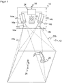
- Figure 1 shows in a schematic three-dimensional representation the general structure of a stereo camera 10 for recording a depth map.
- the stereo camera 10 is only one example of a 3D sensor according to the invention, on which the acquisition of 3D image data is explained.
- Other 3D cameras with acquisition principles such as correlation of image and projected lighting patterns or determination of the time of flight as well as laser scanners would also be conceivable.
- two camera modules 14a, 14b are mounted at a known fixed distance from one another and each record images of the spatial area 12.
- An image sensor 16a, 16b is provided in each camera, usually a matrix-shaped recording chip which records a rectangular pixel image, for example a CCD or a CMOS sensor.
- the two image sensors 16a, 16b together form a 3D image sensor for capturing a depth map.
- the image sensors 16a, 16b are each assigned an objective 18a, 18b with imaging optics, which in practice can be implemented as any known imaging objective.
- the maximum viewing angle of these optics is in Figure 1 represented by dashed lines, each forming a viewing pyramid 20a, 20b.
- An illumination unit 22 is provided between the two image sensors 16a, 16b in order to illuminate the spatial area 12 with a structured pattern.
- the stereo camera shown is accordingly designed for active stereoscopy, in which the pattern also impresses contrasts that can be evaluated everywhere on an inherently structureless scene.
- no or homogeneous lighting is provided in order to evaluate the natural object structures in the spatial region 12, which, however, regularly leads to additional image errors.
- a control and evaluation unit 24 is connected to the two image sensors 16a, 16b and the lighting unit 22.
- the control and evaluation unit 24 can be implemented in a wide variety of hardware, for example digital modules such as Microprocessors, ASICs (Application Specific Integrated Circuit), FPGAs (Field Programmable Gate Array), GPUs (Graphics Processing Unit) or mixed forms of these, which can be freely distributed to internal and external components, whereby external components can also be integrated via a network or a cloud as long as latencies can be controlled or tolerated. Since the generation of the depth map and its evaluation are very computationally intensive, an at least partially parallel architecture is preferably formed.
- the control and evaluation unit 24 generates the structured lighting pattern with the aid of the lighting unit 22 and receives image data from the image sensors 16a, 16b. From this image data, it calculates the 3D image data or the depth map of the spatial area 12 with the help of a stereoscopic disparity estimate.
- the stereo camera 10 is designed for the safe detection of an object in personal protection, preferably fail-safe in the sense of safety standards such as those mentioned in the introduction, in particular according to IEC 61496-4-3.
- the depth map in the control and evaluation unit 24 is preferably first subjected to some preprocessing steps, for example a masking out of the known background.
- the objects 28 in the spatial area 12 are then recognized, it being possible for requirements to be placed on relevant objects 28, for example a minimum size corresponding to a required detection capability. Filters based on a body model for more robustness are also conceivable, for example in the form that as in EP 3 200 122 A1 finely captured objects are only relevant if they are in the vicinity of a coarsely captured object.
- the shortest distance from the machine 26 to the next object is then calculated among the remaining objects 28.
- the projective shadow of the object 28 is taken into account, for example by assuming the shadowed area as a precaution as occupied by an object. This prevents a security-relevant object 28 from being overlooked in a shading area that is not visible from the central perspective of the stereo camera 10.
- the respective current shortest distance is provided cyclically or acyclically at a safe interface 30. Typical output rates are several times per second, but less frequent updating is also conceivable, depending on the required and possible response time of the stereo camera 10.
- a higher-level controller connected to the safe interface 30, in particular that of the machine 26, evaluates the shortest distance to fulfill a safety function, for example speed-and-separation monitoring according to ISO / TS 15066, and compares the shortest distance with a required safety distance according to ISO 13855, for example.
- a safety-related reaction is initiated, for example to stop the machine 26, to slow it down or to allow it to evade so that continuously the required safety distance between man and machine is maintained or the machine is put into a safe state.
- the reaction can depend on other conditions such as the speeds or the nature of object 28 and machine area 26 of the impending collision.
- the machine 26 itself is observed and the shortest distance to it is determined. In practice, however, this does not happen due to the very complex shape and dynamics. Instead, the machine 26 is modeled according to the invention as what are known as danger spots.
- the Figures 2 and 3 show an exemplary scenery in a plan view or three-dimensional representation.
- the monitoring is carried out here, for example, by means of a sensor network made up of two 3D sensors 10a-b, for example stereo cameras such as to Figure 1 explained, which are only represented by their respective field of view pyramids.
- the use of two 3-D sensors 10a-b is an example; instead, a single sensor or a larger 3-D sensor network can be used in order to expand the field of view or to gain additional perspectives.
- the 3D sensors 10a-b only secure towards the front, a physical barrier 32 prevents access from to the right. At the back and left, walls, other physical barriers, 3D sensors or, for example, light grids can complete the protection.
- Two danger spots 26a-b are configured around the machine 26 by way of example.
- the danger points 26a-b are spatial areas in which the machine 26 performs work movements in a respective time segment.
- the danger points 26a-b can surround the machine 26 with some distance in order to allow sufficient play for the working movements.
- several danger spots 26a-b surround several machines 26 and / or several movable subsections of a machine 26.
- Danger spots 26a-b can be rigid and include all conceivable work movements.
- danger points 26a-b are defined for partial sections of the work movement, which are used in a sequence corresponding to the process and which are smaller and better adapted.
- a danger point 26a-b itself is preferably viewed as being free of objects 28 to be detected, or rather as being blocked by the machine 26.
- the machine 26 itself naturally also forms an object 28, which is initially detected by the 3D sensors 10a-b.
- the differentiation between machine 26 and object 28 within danger point 26a-b would, however, be extremely difficult and prone to errors, with the result that the distance between machine 26 and itself is calculated and an unnecessary safety reaction then takes place. Since the danger point 26a-b together with the projective covering and shading areas are masked out for object recognition, the dynamics of the machine 26 within the danger point 26a are irrelevant. In terms of safety, this is not a problem, because each object 28 is recognized in good time when it approaches a danger point 26a-b.
- a hazard point 26a-b For efficient and safe monitoring, however, there are now some requirements for the configuration of a hazard point 26a-b.
- a hazard point 26a-b For example, for the left 3D sensor 10a on the right-hand side of the danger point 26a, denoted by an arrow, a non-visible area is created which is shaded by the danger point 26a.
- the configuration of the danger points 26a-b and the sensor network of the 3D sensors 10a-b must ensure that no object 28 goes undetected without timely safe reaction, got into a danger spot 26a-b. In the case of the critical point indicated by arrows, this is solved by the right 3D sensor 10b taking over the monitoring with a perspective that is more favorable for this.
- the 3D sensors 10a-b can work in their own coordinate system during operation, the configured danger spots 26a-b being converted using the transformations obtained during the registration.
- the 3D sensors 10a-b observe the scene from above, for example by mounting it on the ceiling. This is particularly advantageous, but not absolutely necessary. Different perspectives can also be used in the sensor network in order to effectively reduce shading areas.
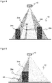
- Figure 4 shows a schematic side view of the spatial area 12 detected by a 3D sensor 10 with two exemplary danger spots 26a-b.
- Different possible shortest distances from the danger points 26a-b and their projective covering and shading areas 34a-b resulting from masking out the danger points 26a-b are drawn in with dashed lines. If the projective shading area 34a-b is taken into account when calculating the distance, the distance is underestimated, which possibly leads to unnecessary safety reactions and thus an impairment of availability. For this reason, distances should preferably always be calculated directly from the danger point 26a-b itself. So that no security problem arises from this, it must then be ensured that an object 28 cannot disappear into the projective shading area 34a-b without approaching a minimum distance beforehand, noticed by the 3D sensor 10.
- danger points 26a-b may only be configured according to the invention in such a way that the outer surfaces of the danger point 26a-b are aligned with at least one 3D sensor 10 of the monitoring sensor network.
- this 3D sensor 10 it should be possible to see the entire outer surface directly, in particular without a line of sight through a danger point 26a-b. There is then no obscuration by the danger point 26a-b, and the 3D sensor 10 can use the shortest distance from the configured danger point 26a-b without a projective shadowing area 34a-b.
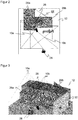
- Figure 6 shows a three-dimensional view of an example of a danger point 26a configured permissibly in this sense.
- the outer surfaces 36 of the danger point 26a are oriented towards at least one of the 3D sensors 10a-b or their respective optical center.
- the configuration according to the invention enforces such outer surfaces 36 or at least indicates which outer surfaces 36 are permissible, for example through coloring.
- Further outer surfaces 38 are marked as invalid, for example shown in red or gray. They cannot be safely monitored by the 3-D sensors 10a-b because they could create security-critical coverings or shadows.
- the setter can change the configuration so that the outer surfaces 38 can be seen, be it by adapting the outer surfaces 38, the position and / or perspective of one of the 3D sensors 10a-b or adding a further 3D sensor. Otherwise, the non-visible outer surfaces 38 are excluded from the monitoring and must be secured in some other way, for example with a fence or a light grille.
- Figure 7 illustrated in a similar view Figure 6 an exemplary correction step of a non-visible outer surface 38.
- a part 36a of the outer surface 38 is reoriented towards the front, making it visible to the 3D sensor 10a and thus permissible for monitoring.
- Figure 8 illustrated in a top view of the situation of the Figure 7 an embodiment of the configuration according to the invention.
- danger points 26a are configured as a polygon in the ground plane and provided with a height. This results in a prism with vertical side surfaces as outer surfaces.
- the polygon is initially not restricted, but should preferably not be self-intersecting and can include any number of support points, so that complex shapes are also possible. This means that there are more configuration options than with conceivable geometric primitives such as cuboids, cylinders or spheres. On the other hand, any meshes would be even more flexible, but difficult to handle both for their definition and for checking and tracing the admissibility in the sense of the mentioned visibility criterion. In general, i.e.
- an outer surface of the danger point 26a-b can be seen if the connecting line from the 3D sensor 10a-b to any point on the outer surface does not have a point of a danger point 26a -b cuts.
- the orientation of a flat outer surface towards the 3D sensor 10ab can be checked with a normal vector n of the outer surface.
- the normal vector n always points outwards from the danger point 26a-b.
- n ⁇ r 0 must apply to the scalar product.
- the connection vector r from the 3D sensor 10 to the surface therefore always points in the opposite direction to the normal vector n.
- danger spots 26a-b which are configured as a prism with vertical side surfaces from a polygon
- this check can be significantly simplified.
- n is perpendicular to the polygon segment under consideration
- r connects the projection of the optical center of the 3D sensor 10 to any point of the polygon segment, for example its start, end or center point.
- the condition for the scalar product remains n ⁇ r ⁇ 0, only that it is now a two-dimensional scalar product of the vectors projected onto the base area.
- the condition clearly means that the 3D sensor 10 with respect to a half-plane 40, which in FIG Figure 9 for example that of the outer surface 36a lies beyond the danger point 26a. This condition must be checked for each segment of the traverse using the corresponding half-planes 40.
- the check preferably takes place during the configuration or only valid polygons can be set up. This means that it is not possible to cover up behind danger spots 26a-b.
- This automatic control procedure has the advantage that only valid configurations can be created and released, at least with regard to the visibility of the side surfaces. The automatic check thus excludes these configuration errors.
- Figure 10 shows again an exemplary schematic side view of the field of view of a 3D sensor 10.
- a conceivable condition at danger spots 26a-b is that they may have any height, but always have to start on the base, which is preferably meant in a broader sense and allows a safe distance of, for example, 300 mm to the floor. This means that no relevant object 28 can disappear under a hazard point 26a-b.
- Floating danger spots 26a are therefore often not advantageous. In the situation of the Figure 10 For most applications, it would probably be better to pull the danger point 26a vertically downwards to the ground within the scope of the configuration than to actually project it obliquely over the shading area 34a.
- the shading areas 34a have mainly been viewed from the point of view of the 3D sensor 10 behind a danger point 26a. Due to the requirement of object-free danger points 26a and their masking out during the object detection, however, a concealment also arises between the danger point 26a and the 3D sensor 10 as part of the respective concealment and shadowing area 34a.
- Figure 12 again illustrates the advantage of the configuration according to the invention. Instead of paying attention to the visibility of the outer surfaces of a danger point 26a-b, it would always be possible to simply add projectively to the danger points 26a-b, that is to add the entire shading areas 34a-b to them.
- a comparison of Figure 6 and 12th shows impressively how much larger the volume occupied by danger spots 26a-b becomes. This also means that the shortest distances to objects 28 are systematically underestimated and thus availability is reduced.
- a hazard point 26a-b is difficult to understand for the fitter, and complex geometries result in the room during the subsequent calculation. Similar problems arise when hazard locations 26a-b are extracted directly from depth maps.
- danger points 26a-b using the work processes of the machine 26 or at least to support the setter in the configuration using the work processes.
- the machine 26 is monitored by one of the 3D sensors via one or more work steps. Monitoring by another 3D sensor that sees the machine 26 from a better or more complete perspective is also conceivable, or with completely different sensors, such as a robot's own sensor system as the machine 26 Machine 26 are at least temporarily occupied, and this information is used to automatically define hazard areas 26a-b, or the information is displayed to illustrate the approximately required hazard area 26a-b to the fitter. It is also conceivable to automatically predefine danger points 26a-b and then to rework them manually.
- the sequence could initially provide for the recording of 3D point clouds of the static scene as a reference and then during the work steps of the machine 26 to be monitored, possibly also several times. A kind of union is formed from this, and 3D points of the reference that are static and not part of a hazard may be ignored.
- a 3D model is created, in particular a convex envelope including projective obscuration from the sensor perspective.
- a 3D model is created for the work steps and the reference, and the 3D model is adjusted in this way.
- the resulting 3D model designates a spatial volume of all points occupied by moving parts of the machine 26. It is then automatically and / or manually reworked to form a permissible hazard point 26a-b, in which all outer surfaces can be viewed by at least one 3D sensor 10a-b.
- a permissible hazard point 26a-b in which all outer surfaces can be viewed by at least one 3D sensor 10a-b.
Landscapes
- Engineering & Computer Science (AREA)
- Physics & Mathematics (AREA)
- General Physics & Mathematics (AREA)
- Theoretical Computer Science (AREA)
- Computer Vision & Pattern Recognition (AREA)
- Signal Processing (AREA)
- Multimedia (AREA)
- Human Computer Interaction (AREA)
- Manufacturing & Machinery (AREA)
- Automation & Control Theory (AREA)
- Optics & Photonics (AREA)
- Robotics (AREA)
- Mechanical Engineering (AREA)
- Length Measuring Devices By Optical Means (AREA)
Claims (14)
- Procédé pour configurer au moins un emplacement de danger (26a-b) à surveiller par au moins un capteur 3D (10, 10a-b), dans lequel la configuration se fait à l'aide d'un logiciel, et l'emplacement de danger (26a-b) est un volume qui est défini par des surfaces extérieures (36, 38) pour sécuriser au moins une machine (26) et qui modélise la machine (26), et les surfaces extérieures (36, 38) sont spécifiées par la configuration,
caractérisé en ce que
pendant la configuration ou après la configuration, on vérifie automatiquement si des surfaces extérieures (36, 38) sont vues par l'un au moins des capteurs 3D (10, 10a-b), de manière à éviter d'emblée, grâce à l'emplacement de danger configuré (32), les problèmes de sécurité dus à l'occultation ou à l'ombrage, du fait que l'installateur est assisté automatiquement et ne peut pas configurer d'emplacements de danger inadmissibles en ce sens, ou reçoit au moins une information relative à des problèmes de sécurité possibles, une surface extérieure pouvant être vue par un capteur 3D (10, 10a-b) si la ligne de liaison du capteur 3D (10, 10a-b) à un point quelconque de la surface extérieure ne coupe aucun point d'un emplacement de danger. - Procédé selon la revendication 1,
dans lequel, pour configurer les surfaces extérieures (36, 38), au moins un tracé polygonal est prédéterminé sur une surface de base, et un prisme avec des surfaces extérieures verticales (36, 38) est généré à partir de celui-ci. - Procédé selon la revendication 1 ou 2,
dans lequel une surface extérieure (36) peut être vue par un capteur 3D (10, 10a-b) lorsque le capteur 3D (10, 10a-b) est positionné au-delà de l'emplacement de danger (26a-b) par rapport au plan (40) dans lequel se situe la surface extérieure (36). - Procédé selon l'une des revendications précédentes,
dans lequel les emplacements de danger (26a-b) ne peuvent être configurés qu'en contact avec le sol ou, dans la mesure où des emplacements de danger (26a-b) suspendus sont néanmoins autorisés, leur zone d'ombre projective (34a-b) est ajoutée à l'emplacement de danger (26a-b). - Procédé selon l'une des revendications précédentes,
dans lequel une surface extérieure (38) qui n'est pas vue par au moins un capteur 3D (10, 10a-b) est marquée pendant la configuration ou n'est pas autorisée du tout. - Procédé selon l'une des revendications précédentes,
dans lequel, lors de la configuration d'une surface extérieure (38) qui n'est pas vue par au moins un capteur 3D (10, 10a-b), une surface extérieure alternative (36) est suggérée automatiquement. - Procédé selon l'une des revendications précédentes,
dans lequel, lors de la configuration d'une surface extérieure (38) qui n'est pas vue par au moins un capteur 3D (10, 10a-b), une perspective modifiée d'un capteur 3D (10, 10a-b) ou une perspective d'un capteur 3D supplémentaire (10, 10a-b) est suggérée automatiquement pour que la surface extérieure (36) soit alors vue. - Procédé selon l'une des revendications précédentes,
dans lequel la machine (26) est observée pendant son mouvement de travail afin de localiser les zones d'espace à englober par l'emplacement de danger (26a-b). - Procédé selon la revendication 8,
dans lequel les zones d'espace à englober sont représentées comme une aide à la configuration de l'emplacement de danger (26a-b). - Procédé selon la revendication 8 ou 9,
dans lequel un emplacement de danger (26a-b) est configuré automatiquement sur la base des zones d'espace à englober. - Procédé selon l'une des revendications précédentes,
dans lequel ledit au moins un emplacement de danger configuré (26a-b) est surveillé par ledit au moins un capteur 3D (10, 10a-b), des objets (28) à proximité de l'emplacement de danger (26a-b) sont détectés à partir de données de mesure du capteur 3D (10, 10a-b), la distance la plus courte entre l'emplacement de danger (26a-b) et les objets (28) est déterminée, et il est décidé à l'aide de cette distance si une réaction de sécurité de la machine (26) a lieu à l'emplacement de danger (26a-b). - Procédé selon la revendication 11,
dans lequel la distance la plus courte aux surfaces extérieures (36) est déterminée sans tenir compte de la zone d'ombre projective (34a-b) de l'emplacement de danger (26a-b). - Procédé selon la revendication 11 ou 12,
dans lequel, lors de la surveillance de l'emplacement de danger (26a-b), les objets à l'emplacement de danger (26a-b) lui-même et dans une zone d'occlusion (34a-b) entre l'emplacement de danger (26a-b) et le capteur 3D (10, 10a-b) sont ignorés. - Dispositif pour configurer au moins un emplacement de danger (26a-b) à surveiller par au moins un capteur 3D (10, 10a-b), dans lequel l'emplacement de danger (26a-b) est un volume qui est défini par des surfaces extérieures (36, 38) pour sécuriser au moins une machine (26) et qui modélise la machine (26), et le dispositif comprend un moyen d'entrée, une unité de commande et d'évaluation et un écran d'affichage, l'unité de commande et d'évaluation étant réalisée pour spécifier des surfaces extérieures (36, 38) de l'emplacement de danger (26a-b) sur la base des entrées du moyen d'entrée, et pour les représenter sur l'écran d'affichage afin de configurer l'emplacement de danger (26a-b) par un procédé selon l'une des revendications 1 à 10.
Priority Applications (3)
| Application Number | Priority Date | Filing Date | Title |
|---|---|---|---|
| EP18176458.0A EP3578320B1 (fr) | 2018-06-07 | 2018-06-07 | Configurer un endroit dangereux surveillé par un capteur tridimensionnel |
| DE102019111641.4A DE102019111641A1 (de) | 2018-06-07 | 2019-05-06 | Konfigurieren einer von einem 3D-Sensor überwachten Gefahrenstelle |
| US16/432,262 US10969762B2 (en) | 2018-06-07 | 2019-06-05 | Configuring a hazard zone monitored by a 3D sensor |
Applications Claiming Priority (1)
| Application Number | Priority Date | Filing Date | Title |
|---|---|---|---|
| EP18176458.0A EP3578320B1 (fr) | 2018-06-07 | 2018-06-07 | Configurer un endroit dangereux surveillé par un capteur tridimensionnel |
Publications (2)
| Publication Number | Publication Date |
|---|---|
| EP3578320A1 EP3578320A1 (fr) | 2019-12-11 |
| EP3578320B1 true EP3578320B1 (fr) | 2021-09-15 |
Family
ID=62563064
Family Applications (1)
| Application Number | Title | Priority Date | Filing Date |
|---|---|---|---|
| EP18176458.0A Active EP3578320B1 (fr) | 2018-06-07 | 2018-06-07 | Configurer un endroit dangereux surveillé par un capteur tridimensionnel |
Country Status (3)
| Country | Link |
|---|---|
| US (1) | US10969762B2 (fr) |
| EP (1) | EP3578320B1 (fr) |
| DE (1) | DE102019111641A1 (fr) |
Families Citing this family (13)
| Publication number | Priority date | Publication date | Assignee | Title |
|---|---|---|---|---|
| DE102018116371B4 (de) * | 2018-07-06 | 2020-08-06 | Sick Ag | 3D-Sensor und Verfahren zum Überwachen eines Überwachungsbereichs |
| US10957109B2 (en) * | 2019-04-16 | 2021-03-23 | International Business Machines Corporation | Dynamic partition of augmented reality region |
| EP3893145B1 (fr) | 2020-04-06 | 2022-03-16 | Sick Ag | Sécurisation d'un endroit dangereux |
| JP7707478B2 (ja) * | 2020-05-12 | 2025-07-15 | ソレマルテック エス.エー. | 作業デバイス |
| CN111650863B (zh) * | 2020-06-09 | 2022-07-08 | 湖南城市学院 | 一种工程安全监控仪及监控方法 |
| US11950567B2 (en) | 2021-03-04 | 2024-04-09 | Sky View Environmental Service Llc | Condor monitoring systems and related methods |
| JP7729067B2 (ja) * | 2021-05-13 | 2025-08-26 | オムロン株式会社 | 領域設定装置、ラック、制御システム、領域設定方法及びプログラム |
| EP4131139B1 (fr) * | 2021-08-03 | 2025-11-26 | Sick Ag | Dispositif capteur et procédé de sécurisation d'une zone de surveillance |
| KR20230057649A (ko) * | 2021-10-22 | 2023-05-02 | 주식회사 한화 | 로봇 안전 감시 시스템 |
| CN114296029B (zh) * | 2021-12-24 | 2022-12-02 | 宁夏广天夏科技股份有限公司 | 一种采掘工作面人员定位方法及系统 |
| CN115272425B (zh) * | 2022-08-29 | 2023-08-15 | 中铁云网信息科技有限公司 | 一种基于三维点云的铁路工地区域入侵检测方法及系统 |
| DE102023102837B3 (de) | 2023-02-06 | 2024-04-25 | K.A. Schmersal Holding Gmbh & Co. Kg | Verfahren zur Definition einer räumlichen Begrenzung eines Schutzbereichs |
| WO2025090002A1 (fr) * | 2023-10-26 | 2025-05-01 | Inter Ikea Systems B.V. | Identification de risques potentiels pour une personne dans un environnement physique |
Family Cites Families (19)
| Publication number | Priority date | Publication date | Assignee | Title |
|---|---|---|---|---|
| US6829371B1 (en) | 2000-04-29 | 2004-12-07 | Cognex Corporation | Auto-setup of a video safety curtain system |
| DE102005063217C5 (de) | 2005-12-22 | 2022-08-18 | Pilz Gmbh & Co. Kg | Verfahren zum Konfigurieren einer Überwachungseinrichtung zum Überwachen eines Raumbereichsund entsprechende Überwachungseinrichtung |
| ATE445172T1 (de) | 2007-08-02 | 2009-10-15 | Sick Ag | Dreidimensionale raumüberwachung mit konfigurationsmodus zum bestimmen der schutzfelder |
| EP2048557B1 (fr) | 2007-10-11 | 2013-03-27 | Sick Ag | Capteur optoélectronique et dispositif mobile ainsi que son procédé de configuration |
| EP2275990B1 (fr) | 2009-07-06 | 2012-09-26 | Sick Ag | Capteur 3D |
| WO2012068329A1 (fr) * | 2010-11-17 | 2012-05-24 | Omron Scientific Technologies, Inc. | Procédé et appareil de surveillance de zones |
| EP2754125B1 (fr) * | 2011-10-14 | 2017-01-18 | Omron Corporation | Procédé et appareil de surveillance volumétrique projective |
| US9530060B2 (en) | 2012-01-17 | 2016-12-27 | Avigilon Fortress Corporation | System and method for building automation using video content analysis with depth sensing |
| DE102012007242A1 (de) | 2012-03-09 | 2013-09-12 | Fraunhofer-Gesellschaft zur Förderung der angewandten Forschung e.V. | Vorrichtung und Verfahren zur sicheren Mensch-Roboter-Kooperation |
| JP5924134B2 (ja) * | 2012-05-30 | 2016-05-25 | セイコーエプソン株式会社 | 侵入検出装置,ロボットシステム,侵入検出方法および侵入検出プログラム |
| JP2015526309A (ja) | 2012-08-31 | 2015-09-10 | リシンク ロボティクス インコーポレイテッド | 安全ロボット動作のためのシステムおよび方法 |
| DE102013104265A1 (de) * | 2013-04-26 | 2014-10-30 | Pilz Gmbh & Co. Kg | Vorrichtung und Verfahren zum Absichern einer automatisiert arbeitenden Maschine |
| US10888998B2 (en) | 2013-10-07 | 2021-01-12 | Abb Schweiz Ag | Method and device for verifying one or more safety volumes for a movable mechanical unit |
| US9452531B2 (en) | 2014-02-04 | 2016-09-27 | Microsoft Technology Licensing, Llc | Controlling a robot in the presence of a moving object |
| ITUB20151930A1 (it) | 2015-07-03 | 2017-01-03 | Soilmec Spa | Sistema e metodo di sicurezza per la rilevazione di una condizione di rischio in una regione situata in prossimita' di una macchina operatrice, quale una macchina di perforazione o simile. |
| EP3142088B1 (fr) * | 2015-09-11 | 2017-11-08 | Sick Ag | Procede de configuration de plusieurs zones partielles d'une zone de protection souhaitee |
| EP3189947A1 (fr) * | 2016-01-07 | 2017-07-12 | Sick Ag | Procede de configuration et de fonctionnement d'une cellule de travail automatisee surveillee et dispositif de configuration |
| EP3200122B1 (fr) | 2016-01-26 | 2022-06-22 | Sick Ag | Capteur optoelectronique et procede de reconnaissance fiable d'objets de taille minimum |
| JP6416980B1 (ja) * | 2017-05-17 | 2018-10-31 | ファナック株式会社 | 監視領域を分割した空間領域を監視する監視装置 |
-
2018
- 2018-06-07 EP EP18176458.0A patent/EP3578320B1/fr active Active
-
2019
- 2019-05-06 DE DE102019111641.4A patent/DE102019111641A1/de not_active Withdrawn
- 2019-06-05 US US16/432,262 patent/US10969762B2/en active Active
Also Published As
| Publication number | Publication date |
|---|---|
| US10969762B2 (en) | 2021-04-06 |
| US20190377322A1 (en) | 2019-12-12 |
| EP3578320A1 (fr) | 2019-12-11 |
| DE102019111641A1 (de) | 2019-12-12 |
Similar Documents
| Publication | Publication Date | Title |
|---|---|---|
| EP3578320B1 (fr) | Configurer un endroit dangereux surveillé par un capteur tridimensionnel | |
| EP3578319B1 (fr) | Procédé de sécurisation d'un endroit dangereux | |
| EP3421189B1 (fr) | Procédé de surveillance d'une machine | |
| DE102007007576B4 (de) | Verfahren und Vorrichtung zum Sichern eines Arbeitsraums | |
| EP3011225B1 (fr) | Dispositif et procédé pour protéger une machine fonctionnant de manière automatisée | |
| EP2275990B1 (fr) | Capteur 3D | |
| DE102009031732B3 (de) | Entfernungsmessender optoelektronischer Sensor | |
| EP3611422B1 (fr) | Dispositif capteur et procédé de sécurisation d'une zone de surveillance | |
| DE102010037744B3 (de) | Optoelektronischer Sensor | |
| EP3200122B1 (fr) | Capteur optoelectronique et procede de reconnaissance fiable d'objets de taille minimum | |
| EP3573021B1 (fr) | Visualisation de données d'image tridimensionnelle | |
| EP2275989B1 (fr) | Caméra 3D stéréoscopique | |
| EP3572971B1 (fr) | Protection d'une zone de surveillance à au moins une machine | |
| WO2004029502A1 (fr) | Procede et dispositif pour securiser une zone de risque | |
| EP3591426A1 (fr) | Capteur 3d et procédé de surveillance d'une zone de surveillance | |
| EP2819109B1 (fr) | Capteur optoélectronique 3D et procédé de reconnaissance d'objets | |
| DE102009026091A1 (de) | Verfahren und System zur Überwachung eines dreidimensionalen Raumbereichs mit mehreren Kameras | |
| EP3893145B1 (fr) | Sécurisation d'un endroit dangereux | |
| EP3588365A1 (fr) | Capteur optoélectronique et procédé d'évaluation sécurisée des données de mesure | |
| DE102010036852B4 (de) | Stereokamera | |
| EP2818824B1 (fr) | Appareil comprenant un capteur optoélectronique 3D et procédé de réconaissance d'objets | |
| EP4516463B1 (fr) | Protection sans contact sur une zone de coopération d'une machine | |
| EP4332902B1 (fr) | Localisation d'un marqueur optique | |
| EP4401045B1 (fr) | Configuration de capteur 3d pour un suivi d'objet sécurisé | |
| DE202018103869U1 (de) | 3D-Sensor zum Überwachen eines Überwachungsbereichs |
Legal Events
| Date | Code | Title | Description |
|---|---|---|---|
| PUAI | Public reference made under article 153(3) epc to a published international application that has entered the european phase |
Free format text: ORIGINAL CODE: 0009012 |
|
| STAA | Information on the status of an ep patent application or granted ep patent |
Free format text: STATUS: THE APPLICATION HAS BEEN PUBLISHED |
|
| AK | Designated contracting states |
Kind code of ref document: A1 Designated state(s): AL AT BE BG CH CY CZ DE DK EE ES FI FR GB GR HR HU IE IS IT LI LT LU LV MC MK MT NL NO PL PT RO RS SE SI SK SM TR |
|
| AX | Request for extension of the european patent |
Extension state: BA ME |
|
| RAP1 | Party data changed (applicant data changed or rights of an application transferred) |
Owner name: SICK AG |
|
| STAA | Information on the status of an ep patent application or granted ep patent |
Free format text: STATUS: REQUEST FOR EXAMINATION WAS MADE |
|
| 17P | Request for examination filed |
Effective date: 20200213 |
|
| RBV | Designated contracting states (corrected) |
Designated state(s): AL AT BE BG CH CY CZ DE DK EE ES FI FR GB GR HR HU IE IS IT LI LT LU LV MC MK MT NL NO PL PT RO RS SE SI SK SM TR |
|
| STAA | Information on the status of an ep patent application or granted ep patent |
Free format text: STATUS: EXAMINATION IS IN PROGRESS |
|
| 17Q | First examination report despatched |
Effective date: 20200430 |
|
| GRAP | Despatch of communication of intention to grant a patent |
Free format text: ORIGINAL CODE: EPIDOSNIGR1 |
|
| STAA | Information on the status of an ep patent application or granted ep patent |
Free format text: STATUS: GRANT OF PATENT IS INTENDED |
|
| INTG | Intention to grant announced |
Effective date: 20210625 |
|
| GRAS | Grant fee paid |
Free format text: ORIGINAL CODE: EPIDOSNIGR3 |
|
| GRAA | (expected) grant |
Free format text: ORIGINAL CODE: 0009210 |
|
| STAA | Information on the status of an ep patent application or granted ep patent |
Free format text: STATUS: THE PATENT HAS BEEN GRANTED |
|
| AK | Designated contracting states |
Kind code of ref document: B1 Designated state(s): AL AT BE BG CH CY CZ DE DK EE ES FI FR GB GR HR HU IE IS IT LI LT LU LV MC MK MT NL NO PL PT RO RS SE SI SK SM TR |
|
| REG | Reference to a national code |
Ref country code: CH Ref legal event code: EP |
|
| REG | Reference to a national code |
Ref country code: DE Ref legal event code: R096 Ref document number: 502018007056 Country of ref document: DE |
|
| REG | Reference to a national code |
Ref country code: IE Ref legal event code: FG4D Free format text: LANGUAGE OF EP DOCUMENT: GERMAN |
|
| REG | Reference to a national code |
Ref country code: AT Ref legal event code: REF Ref document number: 1430170 Country of ref document: AT Kind code of ref document: T Effective date: 20211015 |
|
| REG | Reference to a national code |
Ref country code: LT Ref legal event code: MG9D |
|
| REG | Reference to a national code |
Ref country code: NL Ref legal event code: MP Effective date: 20210915 |
|
| PG25 | Lapsed in a contracting state [announced via postgrant information from national office to epo] |
Ref country code: NO Free format text: LAPSE BECAUSE OF FAILURE TO SUBMIT A TRANSLATION OF THE DESCRIPTION OR TO PAY THE FEE WITHIN THE PRESCRIBED TIME-LIMIT Effective date: 20211215 Ref country code: LT Free format text: LAPSE BECAUSE OF FAILURE TO SUBMIT A TRANSLATION OF THE DESCRIPTION OR TO PAY THE FEE WITHIN THE PRESCRIBED TIME-LIMIT Effective date: 20210915 Ref country code: BG Free format text: LAPSE BECAUSE OF FAILURE TO SUBMIT A TRANSLATION OF THE DESCRIPTION OR TO PAY THE FEE WITHIN THE PRESCRIBED TIME-LIMIT Effective date: 20211215 Ref country code: SE Free format text: LAPSE BECAUSE OF FAILURE TO SUBMIT A TRANSLATION OF THE DESCRIPTION OR TO PAY THE FEE WITHIN THE PRESCRIBED TIME-LIMIT Effective date: 20210915 Ref country code: RS Free format text: LAPSE BECAUSE OF FAILURE TO SUBMIT A TRANSLATION OF THE DESCRIPTION OR TO PAY THE FEE WITHIN THE PRESCRIBED TIME-LIMIT Effective date: 20210915 Ref country code: HR Free format text: LAPSE BECAUSE OF FAILURE TO SUBMIT A TRANSLATION OF THE DESCRIPTION OR TO PAY THE FEE WITHIN THE PRESCRIBED TIME-LIMIT Effective date: 20210915 Ref country code: FI Free format text: LAPSE BECAUSE OF FAILURE TO SUBMIT A TRANSLATION OF THE DESCRIPTION OR TO PAY THE FEE WITHIN THE PRESCRIBED TIME-LIMIT Effective date: 20210915 |
|
| PG25 | Lapsed in a contracting state [announced via postgrant information from national office to epo] |
Ref country code: LV Free format text: LAPSE BECAUSE OF FAILURE TO SUBMIT A TRANSLATION OF THE DESCRIPTION OR TO PAY THE FEE WITHIN THE PRESCRIBED TIME-LIMIT Effective date: 20210915 Ref country code: GR Free format text: LAPSE BECAUSE OF FAILURE TO SUBMIT A TRANSLATION OF THE DESCRIPTION OR TO PAY THE FEE WITHIN THE PRESCRIBED TIME-LIMIT Effective date: 20211216 |
|
| PG25 | Lapsed in a contracting state [announced via postgrant information from national office to epo] |
Ref country code: IS Free format text: LAPSE BECAUSE OF FAILURE TO SUBMIT A TRANSLATION OF THE DESCRIPTION OR TO PAY THE FEE WITHIN THE PRESCRIBED TIME-LIMIT Effective date: 20220115 Ref country code: SM Free format text: LAPSE BECAUSE OF FAILURE TO SUBMIT A TRANSLATION OF THE DESCRIPTION OR TO PAY THE FEE WITHIN THE PRESCRIBED TIME-LIMIT Effective date: 20210915 Ref country code: SK Free format text: LAPSE BECAUSE OF FAILURE TO SUBMIT A TRANSLATION OF THE DESCRIPTION OR TO PAY THE FEE WITHIN THE PRESCRIBED TIME-LIMIT Effective date: 20210915 Ref country code: RO Free format text: LAPSE BECAUSE OF FAILURE TO SUBMIT A TRANSLATION OF THE DESCRIPTION OR TO PAY THE FEE WITHIN THE PRESCRIBED TIME-LIMIT Effective date: 20210915 Ref country code: PT Free format text: LAPSE BECAUSE OF FAILURE TO SUBMIT A TRANSLATION OF THE DESCRIPTION OR TO PAY THE FEE WITHIN THE PRESCRIBED TIME-LIMIT Effective date: 20220117 Ref country code: PL Free format text: LAPSE BECAUSE OF FAILURE TO SUBMIT A TRANSLATION OF THE DESCRIPTION OR TO PAY THE FEE WITHIN THE PRESCRIBED TIME-LIMIT Effective date: 20210915 Ref country code: NL Free format text: LAPSE BECAUSE OF FAILURE TO SUBMIT A TRANSLATION OF THE DESCRIPTION OR TO PAY THE FEE WITHIN THE PRESCRIBED TIME-LIMIT Effective date: 20210915 Ref country code: ES Free format text: LAPSE BECAUSE OF FAILURE TO SUBMIT A TRANSLATION OF THE DESCRIPTION OR TO PAY THE FEE WITHIN THE PRESCRIBED TIME-LIMIT Effective date: 20210915 Ref country code: EE Free format text: LAPSE BECAUSE OF FAILURE TO SUBMIT A TRANSLATION OF THE DESCRIPTION OR TO PAY THE FEE WITHIN THE PRESCRIBED TIME-LIMIT Effective date: 20210915 Ref country code: CZ Free format text: LAPSE BECAUSE OF FAILURE TO SUBMIT A TRANSLATION OF THE DESCRIPTION OR TO PAY THE FEE WITHIN THE PRESCRIBED TIME-LIMIT Effective date: 20210915 Ref country code: AL Free format text: LAPSE BECAUSE OF FAILURE TO SUBMIT A TRANSLATION OF THE DESCRIPTION OR TO PAY THE FEE WITHIN THE PRESCRIBED TIME-LIMIT Effective date: 20210915 |
|
| REG | Reference to a national code |
Ref country code: DE Ref legal event code: R097 Ref document number: 502018007056 Country of ref document: DE |
|
| PLBE | No opposition filed within time limit |
Free format text: ORIGINAL CODE: 0009261 |
|
| STAA | Information on the status of an ep patent application or granted ep patent |
Free format text: STATUS: NO OPPOSITION FILED WITHIN TIME LIMIT |
|
| PG25 | Lapsed in a contracting state [announced via postgrant information from national office to epo] |
Ref country code: DK Free format text: LAPSE BECAUSE OF FAILURE TO SUBMIT A TRANSLATION OF THE DESCRIPTION OR TO PAY THE FEE WITHIN THE PRESCRIBED TIME-LIMIT Effective date: 20210915 |
|
| 26N | No opposition filed |
Effective date: 20220616 |
|
| PG25 | Lapsed in a contracting state [announced via postgrant information from national office to epo] |
Ref country code: SI Free format text: LAPSE BECAUSE OF FAILURE TO SUBMIT A TRANSLATION OF THE DESCRIPTION OR TO PAY THE FEE WITHIN THE PRESCRIBED TIME-LIMIT Effective date: 20210915 |
|
| PG25 | Lapsed in a contracting state [announced via postgrant information from national office to epo] |
Ref country code: MC Free format text: LAPSE BECAUSE OF FAILURE TO SUBMIT A TRANSLATION OF THE DESCRIPTION OR TO PAY THE FEE WITHIN THE PRESCRIBED TIME-LIMIT Effective date: 20210915 Ref country code: IT Free format text: LAPSE BECAUSE OF FAILURE TO SUBMIT A TRANSLATION OF THE DESCRIPTION OR TO PAY THE FEE WITHIN THE PRESCRIBED TIME-LIMIT Effective date: 20210915 |
|
| REG | Reference to a national code |
Ref country code: CH Ref legal event code: PL |
|
| REG | Reference to a national code |
Ref country code: BE Ref legal event code: MM Effective date: 20220630 |
|
| PG25 | Lapsed in a contracting state [announced via postgrant information from national office to epo] |
Ref country code: LU Free format text: LAPSE BECAUSE OF NON-PAYMENT OF DUE FEES Effective date: 20220607 Ref country code: LI Free format text: LAPSE BECAUSE OF NON-PAYMENT OF DUE FEES Effective date: 20220630 Ref country code: IE Free format text: LAPSE BECAUSE OF NON-PAYMENT OF DUE FEES Effective date: 20220607 Ref country code: CH Free format text: LAPSE BECAUSE OF NON-PAYMENT OF DUE FEES Effective date: 20220630 |
|
| PG25 | Lapsed in a contracting state [announced via postgrant information from national office to epo] |
Ref country code: BE Free format text: LAPSE BECAUSE OF NON-PAYMENT OF DUE FEES Effective date: 20220630 |
|
| PG25 | Lapsed in a contracting state [announced via postgrant information from national office to epo] |
Ref country code: MK Free format text: LAPSE BECAUSE OF FAILURE TO SUBMIT A TRANSLATION OF THE DESCRIPTION OR TO PAY THE FEE WITHIN THE PRESCRIBED TIME-LIMIT Effective date: 20210915 Ref country code: CY Free format text: LAPSE BECAUSE OF FAILURE TO SUBMIT A TRANSLATION OF THE DESCRIPTION OR TO PAY THE FEE WITHIN THE PRESCRIBED TIME-LIMIT Effective date: 20210915 |
|
| PG25 | Lapsed in a contracting state [announced via postgrant information from national office to epo] |
Ref country code: HU Free format text: LAPSE BECAUSE OF FAILURE TO SUBMIT A TRANSLATION OF THE DESCRIPTION OR TO PAY THE FEE WITHIN THE PRESCRIBED TIME-LIMIT; INVALID AB INITIO Effective date: 20180607 |
|
| PG25 | Lapsed in a contracting state [announced via postgrant information from national office to epo] |
Ref country code: TR Free format text: LAPSE BECAUSE OF FAILURE TO SUBMIT A TRANSLATION OF THE DESCRIPTION OR TO PAY THE FEE WITHIN THE PRESCRIBED TIME-LIMIT Effective date: 20210915 |
|
| REG | Reference to a national code |
Ref country code: AT Ref legal event code: MM01 Ref document number: 1430170 Country of ref document: AT Kind code of ref document: T Effective date: 20230607 |
|
| PG25 | Lapsed in a contracting state [announced via postgrant information from national office to epo] |
Ref country code: MT Free format text: LAPSE BECAUSE OF FAILURE TO SUBMIT A TRANSLATION OF THE DESCRIPTION OR TO PAY THE FEE WITHIN THE PRESCRIBED TIME-LIMIT Effective date: 20210915 |
|
| PG25 | Lapsed in a contracting state [announced via postgrant information from national office to epo] |
Ref country code: AT Free format text: LAPSE BECAUSE OF NON-PAYMENT OF DUE FEES Effective date: 20230607 |
|
| PG25 | Lapsed in a contracting state [announced via postgrant information from national office to epo] |
Ref country code: AT Free format text: LAPSE BECAUSE OF NON-PAYMENT OF DUE FEES Effective date: 20230607 |
|
| PGFP | Annual fee paid to national office [announced via postgrant information from national office to epo] |
Ref country code: DE Payment date: 20250618 Year of fee payment: 8 |
|
| PGFP | Annual fee paid to national office [announced via postgrant information from national office to epo] |
Ref country code: GB Payment date: 20250620 Year of fee payment: 8 |
|
| PGFP | Annual fee paid to national office [announced via postgrant information from national office to epo] |
Ref country code: FR Payment date: 20250618 Year of fee payment: 8 |
|
| PGFP | Annual fee paid to national office [announced via postgrant information from national office to epo] |
Ref country code: AT Payment date: 20260410 Year of fee payment: 5 |