EP3893145B1 - Sécurisation d'un endroit dangereux - Google Patents
Sécurisation d'un endroit dangereux Download PDFInfo
- Publication number
- EP3893145B1 EP3893145B1 EP20168253.1A EP20168253A EP3893145B1 EP 3893145 B1 EP3893145 B1 EP 3893145B1 EP 20168253 A EP20168253 A EP 20168253A EP 3893145 B1 EP3893145 B1 EP 3893145B1
- Authority
- EP
- European Patent Office
- Prior art keywords
- shortest distance
- detection capability
- height
- safety
- objects
- Prior art date
- Legal status (The legal status is an assumption and is not a legal conclusion. Google has not performed a legal analysis and makes no representation as to the accuracy of the status listed.)
- Active
Links
Images


Classifications
-
- G—PHYSICS
- G06—COMPUTING OR CALCULATING; COUNTING
- G06V—IMAGE OR VIDEO RECOGNITION OR UNDERSTANDING
- G06V20/00—Scenes; Scene-specific elements
- G06V20/60—Type of objects
- G06V20/64—Three-dimensional [3D] objects
-
- G—PHYSICS
- G06—COMPUTING OR CALCULATING; COUNTING
- G06V—IMAGE OR VIDEO RECOGNITION OR UNDERSTANDING
- G06V20/00—Scenes; Scene-specific elements
- G06V20/50—Context or environment of the image
- G06V20/52—Surveillance or monitoring of activities, e.g. for recognising suspicious objects
-
- G—PHYSICS
- G06—COMPUTING OR CALCULATING; COUNTING
- G06V—IMAGE OR VIDEO RECOGNITION OR UNDERSTANDING
- G06V2201/00—Indexing scheme relating to image or video recognition or understanding
- G06V2201/06—Recognition of objects for industrial automation
Definitions
- the invention relates to a method for securing at least one danger point according to the preamble of claim 1 and a corresponding optoelectronic sensor for reliably detecting objects.
- the primary goal of safety technology is to protect people from sources of danger, such as those presented by machines in an industrial environment.
- the machine is monitored with the help of sensors, and accordingly, if there is a situation where a person threatens to come dangerously close to the machine, an appropriate safety measure is taken.
- 3D sensors are used for monitoring. These initially include 3D cameras in different technologies, for example stereoscopy, triangulation, time of flight or evaluation of the disturbance of passive two-dimensional patterns or of projected lighting patterns. In contrast to a conventional two-dimensional camera, such 3D sensors record images that contain distance or depth values in their pixels. This depth-resolved or three-dimensional image data is also referred to as a depth map. Also known are laser scanners scanning in two or all three directions, which also record three-dimensional image data via the respective scanning angle and the measured distance. In many applications, the additional information justifies the greater outlay on equipment and evaluation for generating three-dimensional image data compared to two-dimensional image acquisition.
- Sensors used in safety technology or for personal protection must work particularly reliably and therefore have high safety requirements meet, for example, the ISO 13849 standard for machine safety and the device standard IEC61496 or EN61496 for electro-sensitive protective equipment (ESPE).
- a number of measures must be taken to meet these safety standards, such as reliable electronic evaluation using redundant, diverse electronics, function monitoring or special monitoring of the contamination of optical components.
- it is typically required that an object with a specific minimum size or specific minimum dimensions is reliably detected. This property is called detection ability.
- the current protection concept provides that protective fields are configured that the operating personnel are not allowed to enter during operation of the machine. If the sensor detects an inadmissible intrusion into the protective field, such as an operator's leg, it triggers a safety-related stop of the machine.
- the evaluation should deal with the projective shadow behind an object as if the entire projective shadow belonged to the object. This also applies accordingly to gaps for which there is no valid distance value. The consequence is that gaps are viewed as objects at a distance of zero, i.e. immediately in front of the sensor, and consequently the entire line of sight of the gap is treated as an object. While this provides the necessary security, it is an unfavorable overestimation of the extent of the gap by assuming the worst case.
- the EP 2 275 990 B1 deals with gaps in the depth map and just takes the conservative approach just described.
- a safety-related switch-off command is issued if there are gaps or contiguous pixel areas without gaps that are each larger than the smallest object to be detected, with the size of a gap being projected onto the edge assuming the worst case. This worst case edge is directly in front of the sensor.
- the EP 2 819 109 A1 discloses a 3D sensor that detects objects above a minimum size in a detection field.
- areas of the depth map are compared with suitably chosen templates. Gaps are treated like an object structure directly at the receiving optics.
- the EP 3 200 122 A1 discloses a 3D sensor with reliable detection of objects, in which the depth map is evaluated with a fine and a coarse detection capability. Finely detected objects within the surroundings of a roughly detected object are added to it, isolated finely detected objects are ignored as disturbances. This makes it possible to filter out certain small objects downstream as not relevant to security. However, gaps are treated like objects and must therefore be assumed to be directly in front of the sensor to be on the safe side.
- the hazard zone is a machine or a model of the machine that indicates in which areas of the room an accident can occur if a person, a part of the body or another impermissible object is present there.
- 3D image data from a surveillance area relating to the danger zone are recorded.
- the monitoring area is often related to the danger point in such a way that the danger zone and in particular the machine are at least partially located therein.
- the 3D image data is recorded with a 3D sensor, in particular a 3D camera, and can be in the form of a depth map, 3D point cloud or any other representation.
- the 3D image data are given in arbitrary coordinates. To simplify things, this description is often representative of the idea of surveillance from a bird's eye view. A dimension that is preferably used is then the height above the ground, which can be converted from a distance from the recording sensor if the mounting height is known. In the case of a different perspective, a surface other than the ground can form the reference, without this being further differentiated in language.
- the 3D image data is used for double object recognition with different detection capabilities.
- a shortest distance is then dynamically determined between the detected objects and the danger zone.
- the detection capability given, for example, in millimeters means, in accordance with the usual terminology in security technology, that objects larger than a minimum size defined by the detection capability are reliably detected.
- the detection capability that can be achieved depends on the optical resolution, but also on the evaluation method.
- a first object detection uses a fine detection capability, for example for arm protection
- a second object detection uses a coarse detection capability, for example for body protection.
- the first detection capability is coarser or, when specified in a unit of length such as millimeters, greater than the second detection capability.
- an acquisition with a fine detection capability also reveals the large objects of the acquisition with a coarse detection capability a second time.
- large and small objects are not the relevant category; roughly detected and finely detected objects are differentiated as a result of the respective object detection, without analyzing to what extent roughly detected, large, finely detected and small objects match one another.
- the invention is based on the basic idea of also determining the shortest distance twice, once as the first shortest distance from the finely detected objects and once as the second shortest distance from the roughly detected objects. This seems counter-intuitive since, as already mentioned, the first object recognition does not overlook any objects from the second object recognition. However, such different safety margins in Dependency of the detection capability are taken into account.
- the maximum of the two shortest distances is used as the shortest distance for further evaluation.
- the shortest distance is not necessarily the output or evaluation variable itself; it can also be a variable that is related to it, for example the position of the object that is closest to a danger point.
- the invention has the advantage that the smallest possible underestimation of the actual shortest distance is achieved, and thus greater availability.
- the lower the underestimation the later a monitored machine in the danger area must be put into a safe state if the safety distance is not reached or slowed down when approaching.
- overestimating the shortest distance is not permissible, as this no longer guarantees a timely, safe reaction and therefore a potentially dangerous situation arises. So the goal is to get as close to the shortest distance as possible for improved availability.
- this does not apply in the sense of the usual measurement error tolerances, but is asymmetrical: underestimating is not critical, availability is then only impaired to the extent of unsuccessful optimization, while overestimating would affect non-negotiable security.
- the relevant shortest distance is not just the physical distance between the object and the danger point, but a shortest distance taking into account the safety margins to be taken into account according to the relevant standards.
- the advantages mentioned are particularly evident when the 3D image data have gaps, and the invention thus creates greater robustness against interference, such as extraneous light or reflecting objects, which lead to gaps in the depth map.
- the distance to these gaps is significantly less underestimated and in particular is sharply limited by the resolution-dependent safety margin of the coarser detection capability.
- safety-related parameters such as safety margin, detection capability, reaching over and the like, and already the general terms safe or fail-safe are always in the sense of safety-related standards, in particular ISO 13855 and IEC 61496-4-3 or their applicable equivalent to understand.
- the fine detection capability is preferably designed for arm protection and the coarse detection capability for body protection, in particular at 40 mm or 55 mm for arm protection and 120 mm or 200 mm for body protection.
- the invention is not restricted to these numerical values, but they are particularly suitable. Better protection than arm protection can hardly be realistically achieved with today's means of capturing and evaluating 3D image data, and a coarse detection capability for body protection is a particularly advantageous supplement to a fine detection capability for arm protection.
- the description of the figures specifies the necessary calculation rules with which the safety standards are met in the case of deviating numerical values for the detection capabilities.
- body recognition, leg recognition, arm recognition, hand recognition or finger recognition with exemplary numerical values of 200 mm, 150 mm, 120 mm, 70 mm, 55 mm, 40 mm, 20 mm or 14 mm is possible . Not all combinations can be formed, only those in which the fine detection capability recognizes the smaller body part. There can thus be an embodiment in which the coarse detection capability enables leg detection, while in another embodiment only the fine detection capability resolves legs.
- the difference between a resolution-dependent component of a safety margin for both detection capabilities is preferably added to the second shortest distance.
- the resolution-related component C of the safety margin is defined in the safety standards and is explained in more detail in the context of the description of the figures. To put it bluntly, this should take into account how much closer a smaller part of the body that is no longer reliably detected with the respective detection capability can already have come to the danger point in the worst case when an object is detected, for example the outstretched arm compared to a detected body position. Said difference is added in this embodiment in order to create comparable conditions in both detection capabilities. With a rough detection capability of 200 mm, a difference of 462 mm or 642 mm is added as preferred numerical values if the fine detection capability is 55 mm or 40 mm.
- a resolution-dependent component of a safety margin is preferably taken into account, which corresponds to the fine detection capability.
- the numerical values can be determined in particular using the formula 208 mm + 12 mm * (fine detection capability - 40), and this results, for example, in 388 mm with a fine detection capability of 55 mm or 208 mm with a fine detection capability of 40 mm.
- Finely detected objects that are not in the vicinity of a roughly detected object or are not connected thereto are preferably ignored.
- Such isolated finely detected objects are believed to be artifacts. This is based on the consideration that relevant finely detected objects are smaller body parts, such as an arm, and these cannot occur in isolation, but only in connection with the associated larger body part, such as the torso or the body itself. With this filtering, interference can be detected and be excluded, so that unnecessary underestimations of the shortest distance are avoided and availability is increased.
- Mirror-inverted to hide isolated, finely detected objects combination objects (connected components) can be formed from roughly detected objects and finely detected objects located in their vicinity, such non-isolated, finely detected objects can accordingly be connected to roughly detected objects.
- the environment can be defined by a search radius or a mask, with the expansion preferably being based on the resolution-dependent portion of a safety margin, since this ultimately also goes back to the maximum size of the respective body part, such as an arm.
- a search radius or a mask for further details, refer to the one already mentioned in the introduction EP 3 200 122 A1 referred.
- Gaps in the 3D image data are preferably treated as an object at a specified height, which corresponds to a height to protect against reaching over.
- the term gaps is representative of the terms gaps, defects or holes that are also used. Gaps are treated as foreground and therefore object, so it is assumed, to be safe, that each gap hides an object.
- the pixels in the gap are set to the specified height, in a 3D point cloud, measurement points are added at the specified height over the extent of the gap.
- Gaps only have to be considered in security-relevant sub-areas of the monitoring area, the monitoring area that can actually be detected may be larger, but configured within it a workspace and determined by this limitation that no security monitoring needs to be done outside.
- gaps are set to a zero distance value or a maximum height directly in front of the sensor capturing the 3D image data. This is also conceivable in combination with the invention, but the height described here is more advantageous since the shortest distance is less overestimated.
- safety can already be guaranteed if, instead of the maximum height, a height is selected at which reaching over is definitely not possible. Reaching over, also known as reaching over, is a technical term in safety standards and, very descriptively and in keeping with the term, means that someone is attempting to reach or reach over the guard.
- the height required to protect against reaching over can be determined, for example, with Table 1 "Reaching over the vertical protective field of an electro-sensitive protective device" from the safety standard EN 13855. To put it in a nutshell, the level is selected so that no additional supplement C RO has to be taken into account to protect against reaching over, because this is already sufficiently taken into account by the sum of the resolution-related component and detection capability C+d.
- a reliability measure is preferably determined during the acquisition of the 3D image data, and safety-relevant partial areas in which the reliability measure falls below a reliability threshold are treated as gaps and thus objects at the specified height. So this is a possible criterion for assessing where the 3D image data has gaps. For example, when estimating the disparity of a stereo camera, a quality measure for the respective correlation and thus the resulting distance value is generated at the same time. Gaps are then not only sub-areas of the monitoring area in which no distances could be recorded at all, but also those in which the estimate is not considered to be sufficiently reliable.
- the gaps which are assumed to be fictitious objects, preferably pass through a detection, in the same way as objects that are actually detected, to determine whether they are also security-relevant objects. For example, small gaps and objects can be eliminated, a body model can be used for filtering, or it can be like in EP 3 200 122 A1 finely detected objects added to a neighboring coarsely detected object or isolated finely detected objects ignored.
- Gaps are preferably treated as objects at a first height in the first object recognition and at a second height in the second object recognition, the first height being greater than the second height.
- an arm can reach higher than the torso, i.e. leaning or bending over.
- a lower height can thus be used for the coarse detection capability, and this ultimately leads to an even smaller overestimation of the shortest distance.
- a general upper limit for height can be given as 2.40 m, which is a generous estimate of the maximum height. It is still conceivable that a tall person would stretch out his fingertips up to this height, but would not reach into the danger zone undetected at this height.
- Increasingly sharper preferred numerical values for the first height are a range of [1.80 m; 2.40m], [1.80m; 2.20 m] or a value of 2.00 m with a tolerance of a few centimeters if necessary and for the second height a range [1.00 m; 1.60m], [1.20m; 1.40 m] or a value of 1.20 m again with a certain tolerance.
- the object recognition and/or the determination of the first shortest distance and the second shortest distance is preferably carried out using two channels, in particular on diverse-redundant channels, on one channel for the fine detection capability and on the other channel for the coarse detection capability.
- a two-channel evaluation with subsequent mutual checking of the results is one possibility for a reliable evaluation.
- the two channels can be set up in the same way for a redundant evaluation or with different hardware and/or software for a diversitary-redundant evaluation.
- the responsibility of the channels for a detection capability preferably changes. As a result, errors in the evaluation are detected even more reliably.
- a change takes place, for example, after each calculation, cyclically or on request.
- the object detection is carried out twice or more anyway before a decision about a safety-related reaction is made. Then the change can already take place within these repetitions.
- a decision is preferably made on the basis of the shortest distance as to whether a safety-related reaction is to be initiated. Depending on the situation, this can be slowing down, evading or stopping a machine or other source of danger represented by the danger point, but also, for example, closing or locking a safety door.
- a number of shortest distances to a number of danger points are preferably determined, and a shortest distance is determined as the minimum of the number of shortest distances. In this way, for example, several machines or several dangerous sections of a machine can be secured. The shortest distance across all danger spots can be found very easily as a minimum and evaluated. Alternatively, however, a respective shortest distance to the next i hazard points or all hazard points can be determined and a decision can be made about the safety-related reaction using a more complex method than simply taking into account the globally shortest distance, for example if the intensity of the hazard is different at the hazard points.
- An inventive optoelectronic sensor for reliable detection of objects of a minimum size specified by a detection capability in a surveillance area has at least one image sensor for capturing 3D image data of the surveillance area and a control and evaluation unit that is designed for an embodiment of the inventive method.
- the sensor is preferably safe, ie designed for a safety-related application, and for this purpose meets the standards mentioned in the introduction or corresponding ones, in order to secure a hazardous area.
- the 3D camera particularly preferably uses a triangulation principle in which two camera images of a moving camera or a stereo camera are correlated with one another, or alternatively an illumination pattern is correlated with a camera image in order to estimate disparities and determine distances therefrom.
- a laser scanner is also a 3D sensor, because it generates 3D point clouds, which are limited to one scanning plane with a classic laser scanner. This limitation does not apply to a laser scanner if the scanning is moved in elevation or several scanning beams are shifted in elevation.
- the optoelectronic sensor preferably has a safe output at which the shortest distance from at least one danger point and/or the position of the object at the shortest distance from at least one danger point is output.
- a binary signal is output via such an output interface, whether there is a protective field violation (OSSD, Output Signal Switching Device).
- OSD Output Signal Switching Device
- binary protection signals are no longer generated and output by the sensor itself. Instead, the information required for this is provided securely, very compactly and easily accessible, and the actual safety assessment takes place downstream. This information takes the place of the previously used binary safety signal at the safe output, which is consequently no longer designed as an OSSD.
- a connected system such as a safety controller, the higher-level controller of a robot cell or the controller of the machine itself, from which the danger point is derived, can determine whether there is a danger based on the shortest distance or distances and takes over the actual safety function. Instead of a shortest distance, values can be output that contain equivalent information, in particular the position of the closest object to a danger point, which differs from it only in elementary geometric calculations.
- figure 1 shows in a schematic three-dimensional representation the general structure of a stereo camera 10 for recording a depth map.
- the stereo camera 10 is just one example of a sensor according to the invention, on the basis of which the acquisition of 3D image data is explained.
- Other 3D cameras with detection principles such as correlation of image and projected lighting pattern or determination of the time of flight of light as well as laser scanners would also be conceivable.
- two camera modules 14a, 14b are mounted at a known, fixed distance from one another and each record images of the spatial area 12.
- An image sensor 16a, 16b is provided in each camera, usually a matrix-shaped recording chip which records a rectangular pixel image, for example a CCD or a CMOS sensor.
- the two image sensors 16a, 16b together form a 3D image sensor for capturing a depth map.
- the image sensors 16a, 16b are each assigned a lens 18a, 18b with imaging optics, which in practice can be implemented as any known imaging lens.
- the maximum viewing angle of these optics is in figure 1 represented by dashed lines, each forming a viewing pyramid 20a, 20b.
- the effective field of view for a stereo method is limited to the overlap area. For a larger field of vision, several stereo cameras can be combined side by side or from another perspective, with mixed systems with 3D sensors using different technologies also being conceivable.
- An illumination unit 22 is provided between the two image sensors 16a, 16b in order to illuminate the spatial region 12 with a structured pattern.
- the stereo camera shown is therefore designed for active stereoscopy, in which the Pattern imprints everywhere evaluable contrasts even on a structureless scenery. Alternatively, no lighting or homogeneous lighting is provided in order to evaluate the natural object structures in the spatial area 12, which, however, regularly leads to additional image errors.
- a control and evaluation unit 24 is connected to the two image sensors 16a, 16b and the lighting unit 22 .
- the control and evaluation unit 24 can be implemented in a wide variety of hardware, for example digital components such as microprocessors, ASICs (Application Specific Integrated Circuits), FPGAs (Field Programmable Gate Arrays), GPUs (Graphics Processing Units) or mixed forms thereof, which can be set to any internal and External components can be distributed, with external components also being able to be integrated via a network or a cloud, provided that latencies can be controlled or tolerated. Since the creation of the depth map and its evaluation are very computationally intensive, an at least partially parallel architecture is preferably formed.
- the control and evaluation unit 24 generates the structured illumination pattern with the aid of the illumination unit 22 and receives image data from the image sensors 16a, 16b. From this image data, it calculates the 3D image data or the depth map of the spatial area 12 with the aid of a stereoscopic disparity estimate.
- the entire detectable spatial area 12 or also the working area can be restricted via a configuration, for example in order to hide disruptive or unnecessary areas.
- An important security application of the stereo camera 10 is the monitoring of a machine 26 in the figure 1 is symbolized by a robot.
- Machine 26 may also be much more complex than shown, consisting of many parts, or even actually an assembly of multiple machines, such as multiple robots or robotic arms.
- the control and evaluation unit 24 checks where an object 28, represented as a person, is located in relation to the machine 26.
- a shortest distance between an object 28 and the machine 26 is output via a safe interface 30, either directly to the machine 26 or to an intermediate station such as a safe controller.
- the shortest distance must not be confused with the distance from the stereo camera 10 to object points in the spatial area 12, ie the depth values.
- the stereo camera 10 is preferably designed to be fail-safe in terms of safety standards such as those mentioned in the introduction. Instead of the shortest distance can a variable can be output from which the shortest distance can be easily determined, such as the object position of the object closest to the machine 26 .
- a safety-related reaction is initiated in order, for example, to stop the machine 26, brake it or allow it to take evasive action. Whether this is necessary can depend not only on the shortest distance but also on other conditions, such as the speeds or directions of movement or the nature of object 28 and machine area 26 of the imminent collision.
- FIG 2 shows a schematic side view of a monitoring situation.
- the machine 26 is advantageously modeled here as a danger point 26a.
- This is a spatial area in which the machine 26 performs work movements in a given period of time or which is otherwise associated with hazards from the machine 26.
- the danger point 26a can surround the machine 26 at a certain distance in order to allow sufficient play for the working movements.
- Multiple danger points 26a surround multiple machines 26 and/or multiple moving sections of a machine 26, if required.
- Hazard points 26a can be rigid and include all conceivable work movements.
- danger spots 26a are defined for partial sections of the work movement, which are used in a sequence corresponding to the process and which are smaller and better adapted.
- the danger point 26a itself is preferably regarded as being free of objects 28 to be detected, or rather as being blocked by the machine 26 .
- the danger point 26a is preferably deliberately ignored in the evaluation and the danger point 26a is modeled as an empty block free of objects 28 in order to monitor and determine the shortest distances to simplify, because the dynamics of the machine 26 within the danger point 26a plays no role. This is unproblematic in terms of safety, since each object 28 is recognized in good time when it approaches the danger point 26a.
- the control and evaluation unit 24 calculates how to figure 1 continuously mentions the shortest distance between hazard 26a and object 28, preferably including respective projective shadows. For this purpose, the minimum of the distances between the points in an area 28a shadowed by the object 28 and the points of the danger point 26a around the machine 26, possibly including the projective shadow, are determined.
- the resulting shortest distance 32 is in figure 2 drawn in by an arrow which connects the next point of the shaded area 28a to the next point of the danger point 26a.
- This shortest distance is provided cyclically or acyclically at the secure interface 30, alternatively an equivalent output variable such as an object closest to the danger point 26a, preferably including its next object point that determines the distance.
- Typical output rates are several times per second, but less frequent updating is also conceivable, depending on the required and possible response time of the stereo camera 10.
- a higher-level controller connected to the safe interface 30, in particular that of the machine 26, plans, if necessary, depending on the shortest distance the next work step, reduces the work speed or, if necessary, stops the machine 26 in a safety-related manner, so that the required safety distance between man and machine is maintained throughout.
- the safety assessment of the shortest distances takes place in the control and evaluation unit 24.
- isolated small objects are preferably ignored or, in accordance with a simple body model, small objects in the vicinity of a large object are added to the large object.
- objects are detected once in body resolution and once in arm resolution with a detection capability of 200 mm and 55 mm, respectively, and only arm detections that are associated with body detections remain.
- each valid Object detection a distance or depth value can be determined by the stereo camera 10.
- a possible representation is a so-called detection depth map, the pixels of which contain a distance value wherever a valid object 28 was detected at the respective lateral position.
- valid means, for example, that the object 28, even after filtering with a minimum size, a body model, a connection with a roughly recorded object as in EP 3 200 122 A1 or the like is still considered relevant and is located in a security-relevant area. Areas in which no valid object 28 was detected are empty in the detection depth map.
- problematic areas which are alternatively also referred to as flaws, holes or gaps, must be taken into account in the detection depth map, specifically as (fictitious) objects at a predetermined distance from the stereo camera 10.
- Small isolated gaps are preferred, as are small isolated objects already filtered out.
- the pixels in a gap are assigned a zero spacing immediately in front of the stereo camera 10 .
- the availability is consequently improved if the greatest possible distance from the stereo camera 10 is specified, in other words, in the advantageous illustrated perspective from above, the lowest possible height above a base area.
- a height is preferably selected at the same time that is sufficient to prevent reaching over or reaching over, for example according to ISO 13855:2010. Then there are shorter lines of sight, as in figure 2 for an example gap 34a.
- figure 3 illustrates how the consideration of gaps 34a-b at a height analogous to the secure protection against reaching over, here for example at 2.0 m above the ground, the shortest distances are less overestimated and thus the availability is improved.
- This step accordingly EP 3 572 971 A1 is advantageous, but the invention is not limited to this, but can alternatively, for example, set gaps 34a-b quite conservatively to a maximum height directly at stereo camera 10.
- the danger point 26a is higher, and it is in such a case that the height assigned to gaps 34a can become crucial for the calculation of the shortest distance.
- FIG 2 there is the shortest distance 32 to a point in the shaded area 28a.
- a further gap 34b is added at an edge facing the danger point 26a, and the shortest distance 32 here is to the gap 34b or its line of sight. If a greater height were assigned to the gap 34b, an even smaller shortest distance 32 would result, which corresponds to a higher risk and impairs availability. It can also be seen that the lower danger point 26b in figure 2 even if a further gap 34b were added at the edge, it would still have the shortest distance 32 to the shaded area. This underscores once again that the height assigned to a gap 34a-b has an impact on availability, especially in the case of high danger spots 26a.
- a body model specifies the maximum size and maximum length of the extremities, and the person always stands on a defined base. This results in a maximum height above the base area at which the corresponding body parts are still expected or can even overlap and therefore have to be recognized at all. It suffices if the distance value for gaps 34a-b is set to this height.
- the required amount can also be derived from the safety standards or substantiated with them.
- ISO 13855 and IEC/TS 61496-4-3 are used here.
- Corresponding regulations can also be expected in an alternative valid current or future standard.
- Table 1 of ISO 13855:2010 lists different values for C RO for combinations of the height a of the danger zone and the height b of the detection field. In order to be able to monitor danger spots of any height, the maximum of the C RO for all a at a given b is considered here. Alternatively, a table or calculation rule could also be stored in order to take into account the dependency on a for the specifically configured danger spots 26a.
- the maximum height of the detection area means that no objects 28 need to be detected above it, or only their concealment 28a within the detection area is relevant. From this, however, it can be concluded that objects 28 with an unknown distance, ie gaps 34a-b, together with their covering, only have to be viewed up to a maximum of this height.
- the height derived from the standard ensures that the danger point 26a can no longer be reached if the object 28 is detected up to this height or, alternatively, a gap 34a-b is projected at this height.
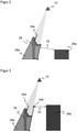
- figure 4 12 is a schematic representation of the field of view 20 of the stereo camera 10 to illustrate the overestimation of the shortest distances despite the shifting of gaps 34 only at height, corresponding to protection against reaching over.
- Preferably only one working area 36 within the viewing area 20 is monitored, which here, for example, has a distance of 300 mm from the floor and a height of 2,000 mm.
- the distance to the floor is intended to prevent the floor from being mistaken for an object 28 to be detected, and at the same time may only be so large that crawling under is impossible.
- a gap 34 is treated as a fictitious object at a safe height, including the visual rays behind it or its projective shadow 38.
- an object 28 not detected by the gap 34 at the lower edge has an actual distance of 40 to the danger point 26a, which would be significantly greater than the safety-related distance 42 from the gap 34 to the danger point 26a.
- an opening angle of the stereo camera 10 of approximately 70°
- an object 28 in the lower left corner and a danger point 26a in the upper right corner there is a considerable overestimation of 1.5 m, and an even greater overestimation is conceivable .
- figure 5 shows in a representation similar figure 4 another example of shortest distance being overestimated despite treating gaps 34 as objects at a safe height.
- a person 28 is in the field of view 20 and the distance from their forearm, which cannot be detected due to the gap 34, is underestimated by about 0.5 m. If the gap 34 is even conservatively shifted up to the level of the stereo camera 10, this further reinforces the underestimation.
- the danger point 26a can also be located outside the working area 36 or the viewing area 20; even then, the shortest distances possibly even more underestimated occur.
- objects 28 are detected twice with different detection capabilities, and a shortest distance of the detected objects 28 from the danger point 26a is determined in each case.
- the safety rating is then based on the larger, more favorable value of the shortest distance. This will now be explained in detail.
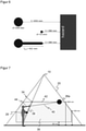
- figure 6 illustrates the resolution-dependent parts of a safety margin for different detection capabilities.
- every detection with arm resolution also includes body detection.
- the body detection itself is crucial for the person recognition and is used for the distance calculation.
- the arm detection is additionally used to increase the resolution and to limit the maximum safety margin without leading to a strong underestimation by gaps 34 . Calculations for two detection abilities are carried out for this. Both lead to valid, safe shortest distances. Depending on the situation, the more favorable, i.e. larger, value is then selected.
- the shortest distance 42 to the danger point 26a is calculated for all objects detected with arm resolution.
- this shortest distance 42 is not to a real object 28, but to a gap 34, which is treated as a fictitious object at a height to protect against reaching over.
- the shortest distance 40 to the danger point 26a is calculated for all objects 28 detected with body resolution. In this case, the supplement 44 explained above for I arm is added. Gaps are rarer at this lower resolution.
- the maximum of the two shortest distances is formed for the further safety evaluation in relation to a required minimum distance, ie for example for output to a connected safety controller or machine or robot controller.
- the shortest distance 40 determined from the body detection is less underestimated and is therefore more favorable. This case is quite relevant in practice.
- Reasons for this are, among other things, that fewer gaps are to be expected in the coarser resolution of the body detection, and even if there are gaps, the objects covered by them are usually closer to the stereo camera 10, such as the head in the example.
- gaps in body detection can still be treated as fictitious objects at a lower height.
- the stereo camera 10 had completely captured the person 28, i.e. if there were no gap 34 in the 3D image data, the real forearm of the person 28 would also be the relevant closest object in the object detection with arm resolution instead of the gap 38 and the shortest distance to this is more favorable than that from body detection.
- the height to which the gaps are shifted depends on the detection capability. It is conceivable to choose this height differently for the individual detection capabilities, for example at 2.00 m for arm protection and at 1.20 m for body protection, since the latter cannot hover freely. This further reduces underestimation of the shortest distance.
- the method described is implemented in a two-channel system or a two-channel control and evaluation unit 24 .
- redundant or diversitary-redundant hardware components are preferably provided for the respective channels.
- the software can be the same for both channels or also vary in a diversitary-redundant manner, which is almost inevitably the case with different hardware.
- the respective results of the channels are then compared with one another or checked for plausibility.
- a particularly advantageous implementation does not carry out the object detection and determination of shortest distances for both detection capabilities in each channel, but rather each channel uses only one detection capability.
- the responsibility for a detection capability is then exchanged between the channels, be it in a second evaluation of the same 3D image data or a later evaluation of other 3D image data. This allows the evaluation to be carried out even more efficiently. There may be additional latencies before one is discovered Errors arise that are either tolerable or limited by very short cycles in the exchange of responsibilities.
Landscapes
- Engineering & Computer Science (AREA)
- Physics & Mathematics (AREA)
- General Physics & Mathematics (AREA)
- Multimedia (AREA)
- Theoretical Computer Science (AREA)
- Length Measuring Devices By Optical Means (AREA)
- Image Analysis (AREA)
Claims (13)
- Procédé de sécurisation d'au moins un emplacement de danger (26, 26a), dans lequel des données d'image 3D d'une zone à surveiller (20, 36) relative à l'emplacement de danger (26, 26a) sont saisies et les données d'image 3D sont évaluées, afin de reconnaître des objets détectés finement (28, 34) lors d'une première reconnaissance d'objet à capacité de détection fine et des objets détectés grossièrement (28) lors d'une deuxième reconnaissance d'objet à capacité de détection grossière, la capacité de détection définissant une taille minimale à partir de laquelle des objets (28) sont détectés de façon sûre, et la distance la plus courte (40, 42) entre les objets détectés (28) et l'emplacement de danger (26, 26a) étant déterminée, et ceci non seulement comme distance physique, mais en prenant en compte des suppléments de sécurité,
caractérisé en ce que
une première distance la plus courte (42) entre les objets détectés finement (28, 34) et l'emplacement de danger (26, 26a) et une deuxième distance la plus courte (40) entre les objets détectés grossièrement (28) et l'emplacement de danger (26, 26a) sont déterminées, en ce que pour déterminer la première distance la plus courte et la deuxième distance la plus courte, différents suppléments de sécurité sont pris en compte en fonction de la capacité de détection, et en ce que lors de la sécurisation, la plus grande valeur parmi la première distance la plus courte (42) et la deuxième distance la plus courte (40) est prise pour base en tant que distance la plus courte. - Procédé selon la revendication 1,
dans lequel la capacité de détection fine est conçue pour la protection des bras, et la capacité de détection grossière est conçue pour la protection du corps, en particulier à 40 mm ou 55 mm pour la protection des bras et à 120 mm ou 200 mm pour la protection du corps. - Procédé selon la revendication 1 ou 2,
dans lequel la différence (44) d'une part, dépendante de la résolution, d'un supplément de sécurité pour les deux capacités de détection est ajoutée à la deuxième distance la plus courte (40), en particulier 462 mm pour une capacité de détection fine de 55 mm et pour une capacité de détection grossière de 200 mm, ou 642 mm pour une capacité de détection fine de 40 mm et pour une capacité de détection grossière de 200 mm. - Procédé selon l'une des revendications précédentes,
dans lequel, lors de l'évaluation de la distance la plus courte, une part d'un supplément de sécurité, laquelle dépend de la résolution et correspond à la capacité de détection fine, est prise en compte, en particulier selon la formule 208 mm + 12 mm ∗ (capacité de détection fine - 40), et donc 388 mm pour une capacité de détection fine de 55 mm, ou 208 mm pour une capacité de détection fine de 40 mm. - Procédé selon l'une des revendications précédentes,
dans lequel des objets détectés finement, qui ne sont pas situés dans un environnement d'un objet détecté grossièrement ou reliés à celui-ci, sont ignorés. - Procédé selon l'une des revendications précédentes,
dans lequel des lacunes (34) dans les données d'image 3D, c'est-à-dire des zones partielles de la zone à surveiller (20, 36) qui sont importantes pour la sécurité et dans lesquelles il n'est pas possible de déterminer une hauteur fiable, sont traitées comme un objet à une hauteur prédéfinie qui correspond à une hauteur pour la sécurisation à l'encontre d'une intervention depuis le côté. - Procédé selon la revendication 6,
dans lequel des lacunes (34) sont traitées comme des objets à une première hauteur lors de la première reconnaissance d'objet et à une deuxième hauteur lors de la deuxième reconnaissance d'objet, la première hauteur étant supérieure à la deuxième hauteur, en particulier la première hauteur étant située dans une plage de [1,80 m ; 2,40 m], [1,80 m ; 2,20 m] ou à peu près à 2,00 m, et la deuxième hauteur étant située dans une plage de [1,00 m ; 1,60 m], [1,20 m ; 1,40 m] ou à peu près à 1,20 m. - Procédé selon l'une des revendications précédentes,
dans lequel la reconnaissance d'objet et/ou la détermination de la première distance la plus courte (42) et de la deuxième distance la plus courte (42) est effectuée sur deux canaux, en particulier sur des canaux redondants diversitaires, sur un canal pour la capacité de détection fine et sur l'autre canal pour la capacité de détection grossière. - Procédé selon la revendication 8,
dans lequel la compétence des canaux pour une capacité de détection est alternée. - Procédé selon l'une des revendications précédentes,
dans lequel il est décidé, sur la base de la distance la plus courte, si une réaction de sécurité est déclenchée. - Procédé selon l'une des revendications précédentes,
dans lequel plusieurs distances les plus courtes par rapport à plusieurs emplacements de danger (26, 26a) sont déterminées, et une distance la plus courte est définie comme étant le minimum desdites plusieurs distances les plus courtes. - Capteur optoélectronique (10), en particulier caméra 3D, pour la reconnaissance sûre d'objets (28) d'une taille minimale prédéfinie par une capacité de détection dans une zone à surveiller (20, 36), le capteur (10) comprenant au moins un capteur d'images (16a-b) pour saisir des données d'image 3D de la zone à surveiller (20, 36) et une unité de commande et d'évaluation (24) qui est réalisée pour un procédé selon l'une des revendications précédentes.
- Capteur optoélectronique (10) selon la revendication 12,
comprenant une sortie sécurisée (30) sur laquelle est délivrée la distance la plus courte par rapport à au moins un emplacement de danger (26, 26a) et/ou la position de l'objet (28, 34) à la distance la plus courte par rapport à au moins un emplacement de danger (26, 26a).
Priority Applications (1)
| Application Number | Priority Date | Filing Date | Title |
|---|---|---|---|
| EP20168253.1A EP3893145B1 (fr) | 2020-04-06 | 2020-04-06 | Sécurisation d'un endroit dangereux |
Applications Claiming Priority (1)
| Application Number | Priority Date | Filing Date | Title |
|---|---|---|---|
| EP20168253.1A EP3893145B1 (fr) | 2020-04-06 | 2020-04-06 | Sécurisation d'un endroit dangereux |
Publications (2)
| Publication Number | Publication Date |
|---|---|
| EP3893145A1 EP3893145A1 (fr) | 2021-10-13 |
| EP3893145B1 true EP3893145B1 (fr) | 2022-03-16 |
Family
ID=70224272
Family Applications (1)
| Application Number | Title | Priority Date | Filing Date |
|---|---|---|---|
| EP20168253.1A Active EP3893145B1 (fr) | 2020-04-06 | 2020-04-06 | Sécurisation d'un endroit dangereux |
Country Status (1)
| Country | Link |
|---|---|
| EP (1) | EP3893145B1 (fr) |
Families Citing this family (2)
| Publication number | Priority date | Publication date | Assignee | Title |
|---|---|---|---|---|
| CN116055539B (zh) * | 2023-03-07 | 2023-10-13 | 深圳华龙讯达信息技术股份有限公司 | 基于工业物联网的设备运行状态监控系统及方法 |
| CN118097565B (zh) * | 2024-04-19 | 2024-07-30 | 国网上海市电力公司 | 一种基于单目视觉的输电通道无效隐患判定方法 |
Family Cites Families (9)
| Publication number | Priority date | Publication date | Assignee | Title |
|---|---|---|---|---|
| US6215898B1 (en) | 1997-04-15 | 2001-04-10 | Interval Research Corporation | Data processing system and method |
| EP2275990B1 (fr) | 2009-07-06 | 2012-09-26 | Sick Ag | Capteur 3D |
| US9094660B2 (en) | 2010-11-11 | 2015-07-28 | Georgia Tech Research Corporation | Hierarchical hole-filling for depth-based view synthesis in FTV and 3D video |
| LU92074B1 (en) | 2012-09-18 | 2014-03-19 | Iee Sarl | Depth image enhancement method |
| EP2819109B1 (fr) | 2013-06-28 | 2015-05-27 | Sick Ag | Capteur optoélectronique 3D et procédé de reconnaissance d'objets |
| EP3200122B1 (fr) | 2016-01-26 | 2022-06-22 | Sick Ag | Capteur optoelectronique et procede de reconnaissance fiable d'objets de taille minimum |
| EP3421189B1 (fr) | 2017-06-28 | 2019-05-22 | Sick AG | Procédé de surveillance d'une machine |
| EP3572971B1 (fr) | 2018-05-22 | 2021-02-24 | Sick Ag | Protection d'une zone de surveillance à au moins une machine |
| EP3578320B1 (fr) | 2018-06-07 | 2021-09-15 | Sick Ag | Configurer un endroit dangereux surveillé par un capteur tridimensionnel |
-
2020
- 2020-04-06 EP EP20168253.1A patent/EP3893145B1/fr active Active
Also Published As
| Publication number | Publication date |
|---|---|
| EP3893145A1 (fr) | 2021-10-13 |
Similar Documents
| Publication | Publication Date | Title |
|---|---|---|
| EP3200122B1 (fr) | Capteur optoelectronique et procede de reconnaissance fiable d'objets de taille minimum | |
| EP3578319B1 (fr) | Procédé de sécurisation d'un endroit dangereux | |
| EP3578320B1 (fr) | Configurer un endroit dangereux surveillé par un capteur tridimensionnel | |
| EP3611422B1 (fr) | Dispositif capteur et procédé de sécurisation d'une zone de surveillance | |
| DE102009031732B3 (de) | Entfernungsmessender optoelektronischer Sensor | |
| DE102010037744B3 (de) | Optoelektronischer Sensor | |
| EP3421189B1 (fr) | Procédé de surveillance d'une machine | |
| EP3011225B1 (fr) | Dispositif et procédé pour protéger une machine fonctionnant de manière automatisée | |
| EP2275989B1 (fr) | Caméra 3D stéréoscopique | |
| EP2095008B1 (fr) | Procédé et dispositif de surveillance d'un espace à trois dimensions | |
| EP2275990B1 (fr) | Capteur 3D | |
| EP3572971B1 (fr) | Protection d'une zone de surveillance à au moins une machine | |
| DE102018116371B4 (de) | 3D-Sensor und Verfahren zum Überwachen eines Überwachungsbereichs | |
| DE102017111885B4 (de) | Verfahren und System zum Überwachen einer Maschine | |
| EP2819109B1 (fr) | Capteur optoélectronique 3D et procédé de reconnaissance d'objets | |
| DE102009026091A1 (de) | Verfahren und System zur Überwachung eines dreidimensionalen Raumbereichs mit mehreren Kameras | |
| EP3893145A1 (fr) | Sécurisation d'un endroit dangereux | |
| EP3588365A1 (fr) | Capteur optoélectronique et procédé d'évaluation sécurisée des données de mesure | |
| EP3651458B1 (fr) | Caméra stéréo sécurisée et procédé de vérification de la capacité de fonctionnement des capteurs d'image | |
| EP3496398B1 (fr) | Caméra stéréo sécurisée et procédé de vérification de la capacité de fonctionnement des capteurs d'image | |
| DE102019127826B4 (de) | Sicherer optoelektronischer Sensor und Verfahren zum Absichern eines Überwachungsbereichs | |
| EP4131139A1 (fr) | Dispositif capteur et procédé de sécurisation d'une zone de surveillance | |
| EP2818824B1 (fr) | Appareil comprenant un capteur optoélectronique 3D et procédé de réconaissance d'objets | |
| EP4401045B1 (fr) | Configuration de capteur 3d pour un suivi d'objet sécurisé | |
| EP4516463A1 (fr) | Protection sans contact sur une zone de coopération d'une machine |
Legal Events
| Date | Code | Title | Description |
|---|---|---|---|
| STAA | Information on the status of an ep patent application or granted ep patent |
Free format text: STATUS: EXAMINATION IS IN PROGRESS |
|
| PUAI | Public reference made under article 153(3) epc to a published international application that has entered the european phase |
Free format text: ORIGINAL CODE: 0009012 |
|
| 17P | Request for examination filed |
Effective date: 20201110 |
|
| AK | Designated contracting states |
Kind code of ref document: A1 Designated state(s): AL AT BE BG CH CY CZ DE DK EE ES FI FR GB GR HR HU IE IS IT LI LT LU LV MC MK MT NL NO PL PT RO RS SE SI SK SM TR |
|
| GRAP | Despatch of communication of intention to grant a patent |
Free format text: ORIGINAL CODE: EPIDOSNIGR1 |
|
| STAA | Information on the status of an ep patent application or granted ep patent |
Free format text: STATUS: GRANT OF PATENT IS INTENDED |
|
| INTG | Intention to grant announced |
Effective date: 20211026 |
|
| GRAS | Grant fee paid |
Free format text: ORIGINAL CODE: EPIDOSNIGR3 |
|
| GRAA | (expected) grant |
Free format text: ORIGINAL CODE: 0009210 |
|
| STAA | Information on the status of an ep patent application or granted ep patent |
Free format text: STATUS: THE PATENT HAS BEEN GRANTED |
|
| AK | Designated contracting states |
Kind code of ref document: B1 Designated state(s): AL AT BE BG CH CY CZ DE DK EE ES FI FR GB GR HR HU IE IS IT LI LT LU LV MC MK MT NL NO PL PT RO RS SE SI SK SM TR |
|
| REG | Reference to a national code |
Ref country code: GB Ref legal event code: FG4D Free format text: NOT ENGLISH |
|
| REG | Reference to a national code |
Ref country code: CH Ref legal event code: EP |
|
| REG | Reference to a national code |
Ref country code: DE Ref legal event code: R096 Ref document number: 502020000796 Country of ref document: DE |
|
| REG | Reference to a national code |
Ref country code: IE Ref legal event code: FG4D Free format text: LANGUAGE OF EP DOCUMENT: GERMAN |
|
| REG | Reference to a national code |
Ref country code: AT Ref legal event code: REF Ref document number: 1476420 Country of ref document: AT Kind code of ref document: T Effective date: 20220415 |
|
| REG | Reference to a national code |
Ref country code: LT Ref legal event code: MG9D |
|
| REG | Reference to a national code |
Ref country code: NL Ref legal event code: MP Effective date: 20220316 |
|
| PG25 | Lapsed in a contracting state [announced via postgrant information from national office to epo] |
Ref country code: SE Free format text: LAPSE BECAUSE OF FAILURE TO SUBMIT A TRANSLATION OF THE DESCRIPTION OR TO PAY THE FEE WITHIN THE PRESCRIBED TIME-LIMIT Effective date: 20220316 Ref country code: RS Free format text: LAPSE BECAUSE OF FAILURE TO SUBMIT A TRANSLATION OF THE DESCRIPTION OR TO PAY THE FEE WITHIN THE PRESCRIBED TIME-LIMIT Effective date: 20220316 Ref country code: NO Free format text: LAPSE BECAUSE OF FAILURE TO SUBMIT A TRANSLATION OF THE DESCRIPTION OR TO PAY THE FEE WITHIN THE PRESCRIBED TIME-LIMIT Effective date: 20220616 Ref country code: LT Free format text: LAPSE BECAUSE OF FAILURE TO SUBMIT A TRANSLATION OF THE DESCRIPTION OR TO PAY THE FEE WITHIN THE PRESCRIBED TIME-LIMIT Effective date: 20220316 Ref country code: HR Free format text: LAPSE BECAUSE OF FAILURE TO SUBMIT A TRANSLATION OF THE DESCRIPTION OR TO PAY THE FEE WITHIN THE PRESCRIBED TIME-LIMIT Effective date: 20220316 Ref country code: BG Free format text: LAPSE BECAUSE OF FAILURE TO SUBMIT A TRANSLATION OF THE DESCRIPTION OR TO PAY THE FEE WITHIN THE PRESCRIBED TIME-LIMIT Effective date: 20220616 |
|
| PG25 | Lapsed in a contracting state [announced via postgrant information from national office to epo] |
Ref country code: LV Free format text: LAPSE BECAUSE OF FAILURE TO SUBMIT A TRANSLATION OF THE DESCRIPTION OR TO PAY THE FEE WITHIN THE PRESCRIBED TIME-LIMIT Effective date: 20220316 Ref country code: GR Free format text: LAPSE BECAUSE OF FAILURE TO SUBMIT A TRANSLATION OF THE DESCRIPTION OR TO PAY THE FEE WITHIN THE PRESCRIBED TIME-LIMIT Effective date: 20220617 Ref country code: FI Free format text: LAPSE BECAUSE OF FAILURE TO SUBMIT A TRANSLATION OF THE DESCRIPTION OR TO PAY THE FEE WITHIN THE PRESCRIBED TIME-LIMIT Effective date: 20220316 |
|
| PG25 | Lapsed in a contracting state [announced via postgrant information from national office to epo] |
Ref country code: NL Free format text: LAPSE BECAUSE OF FAILURE TO SUBMIT A TRANSLATION OF THE DESCRIPTION OR TO PAY THE FEE WITHIN THE PRESCRIBED TIME-LIMIT Effective date: 20220316 |
|
| PG25 | Lapsed in a contracting state [announced via postgrant information from national office to epo] |
Ref country code: RO Free format text: LAPSE BECAUSE OF FAILURE TO SUBMIT A TRANSLATION OF THE DESCRIPTION OR TO PAY THE FEE WITHIN THE PRESCRIBED TIME-LIMIT Effective date: 20220316 Ref country code: PT Free format text: LAPSE BECAUSE OF FAILURE TO SUBMIT A TRANSLATION OF THE DESCRIPTION OR TO PAY THE FEE WITHIN THE PRESCRIBED TIME-LIMIT Effective date: 20220718 Ref country code: ES Free format text: LAPSE BECAUSE OF FAILURE TO SUBMIT A TRANSLATION OF THE DESCRIPTION OR TO PAY THE FEE WITHIN THE PRESCRIBED TIME-LIMIT Effective date: 20220316 Ref country code: EE Free format text: LAPSE BECAUSE OF FAILURE TO SUBMIT A TRANSLATION OF THE DESCRIPTION OR TO PAY THE FEE WITHIN THE PRESCRIBED TIME-LIMIT Effective date: 20220316 Ref country code: CZ Free format text: LAPSE BECAUSE OF FAILURE TO SUBMIT A TRANSLATION OF THE DESCRIPTION OR TO PAY THE FEE WITHIN THE PRESCRIBED TIME-LIMIT Effective date: 20220316 Ref country code: SM Free format text: LAPSE BECAUSE OF FAILURE TO SUBMIT A TRANSLATION OF THE DESCRIPTION OR TO PAY THE FEE WITHIN THE PRESCRIBED TIME-LIMIT Effective date: 20220316 Ref country code: SK Free format text: LAPSE BECAUSE OF FAILURE TO SUBMIT A TRANSLATION OF THE DESCRIPTION OR TO PAY THE FEE WITHIN THE PRESCRIBED TIME-LIMIT Effective date: 20220316 |
|
| REG | Reference to a national code |
Ref country code: DE Ref legal event code: R079 Ref document number: 502020000796 Country of ref document: DE Free format text: PREVIOUS MAIN CLASS: G06K0009000000 Ipc: G06V0010000000 |
|
| PG25 | Lapsed in a contracting state [announced via postgrant information from national office to epo] |
Ref country code: PL Free format text: LAPSE BECAUSE OF FAILURE TO SUBMIT A TRANSLATION OF THE DESCRIPTION OR TO PAY THE FEE WITHIN THE PRESCRIBED TIME-LIMIT Effective date: 20220316 Ref country code: IS Free format text: LAPSE BECAUSE OF FAILURE TO SUBMIT A TRANSLATION OF THE DESCRIPTION OR TO PAY THE FEE WITHIN THE PRESCRIBED TIME-LIMIT Effective date: 20220716 Ref country code: AL Free format text: LAPSE BECAUSE OF FAILURE TO SUBMIT A TRANSLATION OF THE DESCRIPTION OR TO PAY THE FEE WITHIN THE PRESCRIBED TIME-LIMIT Effective date: 20220316 |
|
| REG | Reference to a national code |
Ref country code: DE Ref legal event code: R097 Ref document number: 502020000796 Country of ref document: DE |
|
| REG | Reference to a national code |
Ref country code: BE Ref legal event code: MM Effective date: 20220430 |
|
| PLBE | No opposition filed within time limit |
Free format text: ORIGINAL CODE: 0009261 |
|
| STAA | Information on the status of an ep patent application or granted ep patent |
Free format text: STATUS: NO OPPOSITION FILED WITHIN TIME LIMIT |
|
| PG25 | Lapsed in a contracting state [announced via postgrant information from national office to epo] |
Ref country code: MC Free format text: LAPSE BECAUSE OF FAILURE TO SUBMIT A TRANSLATION OF THE DESCRIPTION OR TO PAY THE FEE WITHIN THE PRESCRIBED TIME-LIMIT Effective date: 20220316 Ref country code: LU Free format text: LAPSE BECAUSE OF NON-PAYMENT OF DUE FEES Effective date: 20220406 Ref country code: DK Free format text: LAPSE BECAUSE OF FAILURE TO SUBMIT A TRANSLATION OF THE DESCRIPTION OR TO PAY THE FEE WITHIN THE PRESCRIBED TIME-LIMIT Effective date: 20220316 |
|
| 26N | No opposition filed |
Effective date: 20221219 |
|
| PG25 | Lapsed in a contracting state [announced via postgrant information from national office to epo] |
Ref country code: BE Free format text: LAPSE BECAUSE OF NON-PAYMENT OF DUE FEES Effective date: 20220430 |
|
| PG25 | Lapsed in a contracting state [announced via postgrant information from national office to epo] |
Ref country code: IE Free format text: LAPSE BECAUSE OF NON-PAYMENT OF DUE FEES Effective date: 20220406 |
|
| PG25 | Lapsed in a contracting state [announced via postgrant information from national office to epo] |
Ref country code: IT Free format text: LAPSE BECAUSE OF FAILURE TO SUBMIT A TRANSLATION OF THE DESCRIPTION OR TO PAY THE FEE WITHIN THE PRESCRIBED TIME-LIMIT Effective date: 20220316 |
|
| PGFP | Annual fee paid to national office [announced via postgrant information from national office to epo] |
Ref country code: FR Payment date: 20230417 Year of fee payment: 4 |
|
| REG | Reference to a national code |
Ref country code: CH Ref legal event code: PL |
|
| PG25 | Lapsed in a contracting state [announced via postgrant information from national office to epo] |
Ref country code: LI Free format text: LAPSE BECAUSE OF NON-PAYMENT OF DUE FEES Effective date: 20230430 Ref country code: CH Free format text: LAPSE BECAUSE OF NON-PAYMENT OF DUE FEES Effective date: 20230430 |
|
| PG25 | Lapsed in a contracting state [announced via postgrant information from national office to epo] |
Ref country code: MK Free format text: LAPSE BECAUSE OF FAILURE TO SUBMIT A TRANSLATION OF THE DESCRIPTION OR TO PAY THE FEE WITHIN THE PRESCRIBED TIME-LIMIT Effective date: 20220316 Ref country code: CY Free format text: LAPSE BECAUSE OF FAILURE TO SUBMIT A TRANSLATION OF THE DESCRIPTION OR TO PAY THE FEE WITHIN THE PRESCRIBED TIME-LIMIT Effective date: 20220316 |
|
| PG25 | Lapsed in a contracting state [announced via postgrant information from national office to epo] |
Ref country code: HU Free format text: LAPSE BECAUSE OF FAILURE TO SUBMIT A TRANSLATION OF THE DESCRIPTION OR TO PAY THE FEE WITHIN THE PRESCRIBED TIME-LIMIT; INVALID AB INITIO Effective date: 20200406 |
|
| PG25 | Lapsed in a contracting state [announced via postgrant information from national office to epo] |
Ref country code: MT Free format text: LAPSE BECAUSE OF FAILURE TO SUBMIT A TRANSLATION OF THE DESCRIPTION OR TO PAY THE FEE WITHIN THE PRESCRIBED TIME-LIMIT Effective date: 20220316 |
|
| GBPC | Gb: european patent ceased through non-payment of renewal fee |
Effective date: 20240406 |
|
| PG25 | Lapsed in a contracting state [announced via postgrant information from national office to epo] |
Ref country code: GB Free format text: LAPSE BECAUSE OF NON-PAYMENT OF DUE FEES Effective date: 20240406 |
|
| PG25 | Lapsed in a contracting state [announced via postgrant information from national office to epo] |
Ref country code: FR Free format text: LAPSE BECAUSE OF NON-PAYMENT OF DUE FEES Effective date: 20240430 |
|
| PG25 | Lapsed in a contracting state [announced via postgrant information from national office to epo] |
Ref country code: GB Free format text: LAPSE BECAUSE OF NON-PAYMENT OF DUE FEES Effective date: 20240406 Ref country code: FR Free format text: LAPSE BECAUSE OF NON-PAYMENT OF DUE FEES Effective date: 20240430 |
|
| PGFP | Annual fee paid to national office [announced via postgrant information from national office to epo] |
Ref country code: DE Payment date: 20250417 Year of fee payment: 6 |
|
| PGFP | Annual fee paid to national office [announced via postgrant information from national office to epo] |
Ref country code: AT Payment date: 20250721 Year of fee payment: 5 |
|
| PG25 | Lapsed in a contracting state [announced via postgrant information from national office to epo] |
Ref country code: TR Free format text: LAPSE BECAUSE OF FAILURE TO SUBMIT A TRANSLATION OF THE DESCRIPTION OR TO PAY THE FEE WITHIN THE PRESCRIBED TIME-LIMIT Effective date: 20220316 |
|
| PG25 | Lapsed in a contracting state [announced via postgrant information from national office to epo] |
Ref country code: SI Free format text: LAPSE BECAUSE OF FAILURE TO SUBMIT A TRANSLATION OF THE DESCRIPTION OR TO PAY THE FEE WITHIN THE PRESCRIBED TIME-LIMIT Effective date: 20220316 |