EP3578324A1 - Système de détecteurs pourvu de détecteurs de distance optoélectroniques - Google Patents
Système de détecteurs pourvu de détecteurs de distance optoélectroniques Download PDFInfo
- Publication number
- EP3578324A1 EP3578324A1 EP19173862.4A EP19173862A EP3578324A1 EP 3578324 A1 EP3578324 A1 EP 3578324A1 EP 19173862 A EP19173862 A EP 19173862A EP 3578324 A1 EP3578324 A1 EP 3578324A1
- Authority
- EP
- European Patent Office
- Prior art keywords
- holder
- distance sensors
- sensor system
- sensors
- shaped housing
- Prior art date
- Legal status (The legal status is an assumption and is not a legal conclusion. Google has not performed a legal analysis and makes no representation as to the accuracy of the status listed.)
- Granted
Links
Images



Classifications
-
- B—PERFORMING OPERATIONS; TRANSPORTING
- B25—HAND TOOLS; PORTABLE POWER-DRIVEN TOOLS; MANIPULATORS
- B25J—MANIPULATORS; CHAMBERS PROVIDED WITH MANIPULATION DEVICES
- B25J19/00—Accessories fitted to manipulators, e.g. for monitoring, for viewing; Safety devices combined with or specially adapted for use in connection with manipulators
- B25J19/06—Safety devices
-
- B—PERFORMING OPERATIONS; TRANSPORTING
- B25—HAND TOOLS; PORTABLE POWER-DRIVEN TOOLS; MANIPULATORS
- B25J—MANIPULATORS; CHAMBERS PROVIDED WITH MANIPULATION DEVICES
- B25J19/00—Accessories fitted to manipulators, e.g. for monitoring, for viewing; Safety devices combined with or specially adapted for use in connection with manipulators
- B25J19/02—Sensing devices
- B25J19/021—Optical sensing devices
-
- F—MECHANICAL ENGINEERING; LIGHTING; HEATING; WEAPONS; BLASTING
- F16—ENGINEERING ELEMENTS AND UNITS; GENERAL MEASURES FOR PRODUCING AND MAINTAINING EFFECTIVE FUNCTIONING OF MACHINES OR INSTALLATIONS; THERMAL INSULATION IN GENERAL
- F16P—SAFETY DEVICES IN GENERAL; SAFETY DEVICES FOR PRESSES
- F16P3/00—Safety devices acting in conjunction with the control or operation of a machine; Control arrangements requiring the simultaneous use of two or more parts of the body
- F16P3/12—Safety devices acting in conjunction with the control or operation of a machine; Control arrangements requiring the simultaneous use of two or more parts of the body with means, e.g. feelers, which in case of the presence of a body part of a person in or near the danger zone influence the control or operation of the machine
- F16P3/14—Safety devices acting in conjunction with the control or operation of a machine; Control arrangements requiring the simultaneous use of two or more parts of the body with means, e.g. feelers, which in case of the presence of a body part of a person in or near the danger zone influence the control or operation of the machine the means being photocells or other devices sensitive without mechanical contact
- F16P3/142—Safety devices acting in conjunction with the control or operation of a machine; Control arrangements requiring the simultaneous use of two or more parts of the body with means, e.g. feelers, which in case of the presence of a body part of a person in or near the danger zone influence the control or operation of the machine the means being photocells or other devices sensitive without mechanical contact using image capturing devices
-
- F—MECHANICAL ENGINEERING; LIGHTING; HEATING; WEAPONS; BLASTING
- F16—ENGINEERING ELEMENTS AND UNITS; GENERAL MEASURES FOR PRODUCING AND MAINTAINING EFFECTIVE FUNCTIONING OF MACHINES OR INSTALLATIONS; THERMAL INSULATION IN GENERAL
- F16P—SAFETY DEVICES IN GENERAL; SAFETY DEVICES FOR PRESSES
- F16P3/00—Safety devices acting in conjunction with the control or operation of a machine; Control arrangements requiring the simultaneous use of two or more parts of the body
- F16P3/12—Safety devices acting in conjunction with the control or operation of a machine; Control arrangements requiring the simultaneous use of two or more parts of the body with means, e.g. feelers, which in case of the presence of a body part of a person in or near the danger zone influence the control or operation of the machine
- F16P3/14—Safety devices acting in conjunction with the control or operation of a machine; Control arrangements requiring the simultaneous use of two or more parts of the body with means, e.g. feelers, which in case of the presence of a body part of a person in or near the danger zone influence the control or operation of the machine the means being photocells or other devices sensitive without mechanical contact
- F16P3/147—Safety devices acting in conjunction with the control or operation of a machine; Control arrangements requiring the simultaneous use of two or more parts of the body with means, e.g. feelers, which in case of the presence of a body part of a person in or near the danger zone influence the control or operation of the machine the means being photocells or other devices sensitive without mechanical contact using electro-magnetic technology, e.g. tags or radar
-
- B—PERFORMING OPERATIONS; TRANSPORTING
- B25—HAND TOOLS; PORTABLE POWER-DRIVEN TOOLS; MANIPULATORS
- B25J—MANIPULATORS; CHAMBERS PROVIDED WITH MANIPULATION DEVICES
- B25J15/00—Gripping heads and other end effectors
Definitions
- the present invention relates to a sensor system with distance sensors.
- the DE 10 2015 112 656 A1 discloses a plurality of optoelectronic distance sensors on a movable machine part.
- robot manufacturers have developed robots with power and force limitation.
- the maximum force that a robot can exert before the movement is automatically stopped can be set here so that, in the event of a robot colliding with a human, a force can not cause serious injury.
- the motor control and the rotary encoders, which determine the position of the robot arm, are safety components with corresponding certification.
- An increasing spread of safe small robots with safe motion controls and force-limited drives reduces the sources of danger on the tool attachment at the end of the robot arm.
- An unsatisfactory problem solved here is the protection of the tool and / or the workpiece on the robot itself.
- the tool itself often consists of sharp or pointed parts, parts that are rotating or hot, etc., in order to perform its task at all. Examples are drills, screwdrivers, cutters, blades, sharp-edged grippers for filigree parts, welding tongs, soldering tips etc.
- a tool attachment usually has small dimensions and is well located. At the same time, the large variety of possible tool geometries, the fast movement in many degrees of freedom and the demand for fast fitting and changing geometries of the tool attachment make new demands on a security solution that existing safety sensors can not or insufficiently fulfill.
- Robots are not finished machines because they are delivered without tools. Even inherently safe MRK robots receive no CE mark for this reason. BWS distinctive safety sensors can be used to secure a robot including tool and workpiece. These sensors must be attached to the robot.
- An object of the invention is to provide an improved sensor system with distance sensors.
- a sensor system with distance sensors for monitoring a danger zone on a movable machine part with at least one protective area wherein a tool and / or a workpiece is arranged on the movable machine part, wherein the distance sensors on a holder on the movable machine part are arranged, wherein a plurality of distance sensors are arranged, wherein the detection beams of the distance sensors form a protective field, wherein the holder has receptacles for the distance sensors, wherein on the holder a first mounting adapter is arranged for attachment of the holder to the movable machine part and a second mounting adapter is arranged on the holder for attachment of the tool to the holder and between the attachment adapters of the holder has a disk-shaped housing, wherein the disk-shaped housing has round surfaces and has no corners on the outer surfaces.
- the fastening adapter for various robot flanges and end effectors is provided here by the fastening adapter.
- the sensor system with the disk-shaped housing with the mounting structure is inherently safe in shape and material, and mechanically stable to prevent manipulation of the safety devices on the one hand and on the other hand to give powers to an optionally power and power limited robot.
- the outer contours of the disc-shaped housing are optionally roundish, also circular or arcuate.
- the design exposed to the worker must not have any sharp edges. Rather, an organic form is provided which attracts a small surface pressure when touched.
- the design exposed to the worker has no gaps where the worker's fingers or clothes could get caught.
- the holder that receives the distance sensors may be monolithic or modular.
- the holder or the receptacle for the distance sensors are firmly connected to the mounting adapters so that it does not come off the mounting adapters in a collision between human and holder. So forces can be passed on to the robot.
- the mechanical design is designed so stable that forces can be passed on to the robot and its power and force limitation.
- the sensor system is used to safely monitor the danger zone or a monitoring area of the movable machine part.
- Safety is safety in the sense of machine safety.
- the EN / IEC 61496 standard regulates the requirements for a safe sensor or a safe non-contact protective device (ESPE) Protection of hazardous areas.
- Machine safety is regulated in the standard EN13849.
- Safety is ensured, for example, by a single-channel design with testing, a two-channel or two-channel diverse design of an evaluation unit for fault detection and functional testing.
- the distance-measuring sensor or distance sensor according to the present invention for example, intrinsically safe and detects internal errors. When an error is detected, for example, an error signal is generated.
- the sensor or distance sensor optionally has a sensor test.
- the evaluation unit detects protective field violations and can output a safety-related switch-off signal in order to stop a dangerous movement of the part or to decelerate the part.
- This can z. B. via secure switching signals e.g. OSSD signals (output safety switching device signals) or safe distance data, distance data or safe location data of the intervention event can be realized.
- the evaluation unit is designed with two channels.
- the plurality of distance sensors are connected to an evaluation unit for evaluation of the distance sensors.
- the distance sensors are optionally arranged along a ring spaced from each other, wherein the sensors form a flat protective field, which extends, for example, cylindrical or frustoconical.
- the distance sensors have uniform distances. Due to the uniform distances of the sensors and each identical angular orientation of the detection beams a nearly uniform resolution within the protective field is achieved.
- the sensors are non-contact distance-measuring distance sensors, the sensors having a detection beam for detecting objects in the monitoring area.
- the distance sensors are preferably optoelectronic distance sensors.
- the distance sensors can each have a linear or flat protective field.
- the flat protective field is fan-shaped with a certain opening angle of for example 2 ° to 20 °.
- the monitoring takes place with a number of simple, one-dimensionally probing distance measuring sensors.
- the distance sensors are light transit time sensors.
- a light transit time sensor or a distance sensor or a light sensor according to the time of flight principle has at least one light transmitter which emits successive light pulses into a measurement area or monitoring area and at least one light receiver which receives the light pulses reflected back from an object in the measurement area and in the form of electrical reception signals a control and evaluation unit supplies, which determines taking into account the speed of light from the time between transmission and reception of the light pulse representative of the distance of the object to the light sensor distance signal.
- non-contact protective devices in addition to the distance sensors and several other sensor technologies in question, namely cameras, such as color or monochrome working 2D cameras or 3D cameras.
- radar sensors ultrasonic sensors, inductive sensors, capacitive sensors or similar sensors are provided.
- the fastening system sensor system may include other sensors used for gesture control.
- the fastening concept with the holder and the fastening adapters can be produced using rapid prototyping methods and adapted to individual customer requirements. Possible here are methods of additive manufacturing.
- a modular construction of the holder is also provided.
- a submodule of the holder contains only a limited number of distance sensors. By combining different submodules any hedging contours can be created.
- an adjustment of the number of sensors is provided: It can, for example, the number of sensors are changed.
- the wavelength of the emitted light of the distance sensors is preferably a wavelength invisible to the human eye, for example infrared light. This makes it more difficult to deliberately intervene in possible protection gaps, as these are not visible.
- the receptacles of the holder for the distance sensors have at least one mechanical attachment for the distance sensors to which the distance sensors can be mounted in at least one predefined position.
- the holder or the receptacle is to be realized so that all distance sensors have a fixed relative position to each other, which is compatible with the hedging concept.
- the distance sensors are optionally installed using the Poka Yoke, after which the sensors automatically have to be installed in the correct position.
- the recording is optionally realized in such a way that several orientations of the individual ESPE are possible, which are compatible with the hedging concept.
- the position and orientation of the individual ESPE sensors is no longer recognizable to the worker in the final installed state, making manipulation more difficult.
- the disc-shaped housing can be opened without loosening the holder of the first mounting adapter or the second Befest Trentsadapater.
- the disc-shaped housing can be opened to mount the distance sensors. Thereafter, the disc-shaped housing is closed again, so that the distance sensors for the worker are no longer recognizable.
- the holder has receptacles for printed circuit boards, electronic assemblies and / or cable connections.
- the holder can simultaneously serve as a receptacle for further electronic assemblies, such as e.g. Cable bus boards, logic units for the first data processing and / or other sensors are used.
- further electronic assemblies such as e.g. Cable bus boards, logic units for the first data processing and / or other sensors are used.
- the cable routing is designed so that the user or worker can not get caught in the cables.
- the holder provides a strain relief of the cables of the ESPE sensors.
- the disk-shaped housing has a safety closure in order to open and close the disk-shaped housing.
- the disc-shaped housing or a closure cap is closed or opened with one or a few safety mechanisms so that the position of the distance sensors inside the holder can not be manipulated.
- the disk-shaped housing and the holder protect the distance sensors from contamination or windscreen contamination as best as possible.
- the disc-shaped housing is elastic, so that upon application of force to the surface of the housing, the housing surface is deformable.
- the deformation can be temporary or permanent.
- the disc-shaped housing is formed of foam, a foamed plastic or other deformable material with a low density.
- the outer skin is, for example, elastic with a spring mechanism and can be made of soft materials with cushioning effect, so that a padded disc-shaped housing is formed.
- the holder has means for looping through or bypassing a plurality of electrical, pneumatic and / or hydraulic connections.
- the holder allows looping or bypassing multiple electrical or pneumatic terminals of the end effectors.
- the cables for controlling the end effector do not influence the sensor function, for example by avoiding occlusion.
- the holder has a colored signal display, the signal display colors being, for example, at least green, yellow and red.
- the fastening concept includes the signal or status display, which serves as an interface between the worker and the safety solution.
- the signal or status display serves as a collaboration interface between the worker and the robot and provides information about the status of the total protection or the individually installed distance sensors.
- the status display has at least three colors on a similar traffic light principle.
- the color green indicates "all OK”.
- the color yellow indicates a warning due to a certain distance or the resulting reduction in the robot speed.
- the color red indicates that the safety distance has been undershot, whereby the robot is stopped.
- the status indicator can have an annular design.
- the signal display or status display can optionally also illuminate parts of the protected area.
- the signal or status display may optionally visualize the protective jacket or the protection volumes realized by the distance sensors, e.g. as a light ring on the work surface.
- a flashing green signal indicates that the robot will start moving.
- the signal display indicates a direction of movement of the holder. This makes it clear to the user or worker in which direction the robot will move. As a result, a risk of injury to the user is minimized.
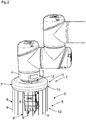
- FIG. 1 and FIG. 2 each show a sensor system 1 with distance sensors 2 for monitoring a danger zone 3 on a movable machine part 4 with at least one protection area 5, wherein on the movable machine part a tool 6 and / or a workpiece is arranged, wherein the distance sensors 2 on a holder 7 on the movable machine part 4 are arranged, wherein a plurality of distance sensors 2 are arranged, wherein the detection beams 9 of the distance sensors 2 form a protective field 10, wherein the holder 7 has receptacles for the distance sensors 2, wherein on the holder 7, a first mounting adapter 12 is arranged to Attachment of the holder 7 on the movable machine part 4 and a second mounting adapter 13 is arranged on the holder for attaching the tool 6 to the holder 7 and between the mounting adapters 12 and 13 of the holder 7 has a disk-shaped housing 14, wherein the disk-shaped housing 14 has a round surface 15 and on the outer surfaces or the side surfaces have no corners.
- the distance sensors may be optoelectronic distance sensors.
- the fastening adapters 12 and 13 an adapter function for various robot flanges and end effectors is provided here by the fastening adapters 12 and 13.
- the sensor system 1 with the disk-shaped housing 14 with the mounting structure is inherently safe in shape and material, as well as mechanically stable on the one hand to prevent manipulation of the sensor system or the safety devices and on the other hand to pass forces to an optionally power and power-limited robot.
- FIG. 2 is provided by the round surface 15 of the disc-shaped housing 14 at any point a possible collision surface and just no edge or corner, whereby a risk of injury is minimized.
- the outer contours of the disk-shaped housing 14 are optionally roundish, also circular or arcuate.
- FIG. 2 An organic form is provided which results in a small surface pressure when touched.
- the design exposed to the worker has no gaps where the worker's fingers or clothes could get caught.
- the holder 7, which receives the distance sensors 2, may be monolithic or modular.
- the holder 7 and the receptacle for the distance sensors 2 are fixedly connected to the mounting adapters 12 and 13, so that they do not detach from the mounting adapters 12 and 13 in a collision between human and holder 2. So forces can be passed on to the robot.
- the mechanical design is designed so stable that forces can be passed on to the robot and its power and force limitation.
- the sensor system 1 serves to safely monitor the danger zone 3 or a monitoring area of the movable machine part by means of the protective field 10.
- the evaluation unit detects protective field violations and can output a safety-related switch-off signal in order to stop a dangerous movement of the movable machine part 4 or the robot or to brake the machine part 4 or the robot.
- This can z. B. via secure switching signals e.g. OSSD signals (output safety switching device signals) or safe distance data, distance data or safe location data of the intervention event can be realized.
- secure switching signals e.g. OSSD signals (output safety switching device signals) or safe distance data, distance data or safe location data of the intervention event can be realized.
- the plurality of distance sensors 2 are connected to an evaluation unit for evaluation of the distance sensors 2.
- the distance sensors 2 are according to FIG. 3 spaced along a ring arranged to each other, wherein the detection beams of the distance sensors 2 form a two-dimensional or spatial protective field, which, for example, cylindrical according to the FIGS. 1 or 2 or, for example, frusto-conical extends.
- the sensors 2 are non-contact distance-measuring distance sensors 2, wherein the sensors according to FIG. 1 and FIG. 2 have a detection beam 9 for detecting objects in the surveillance area.
- the monitoring takes place, for example, with a number of simple, one-dimensionally probing distance measuring sensors 2.
- the distance sensors are 2 light transit time sensors.
- a submodule of the holder 7 in this case contains only a limited number of distance sensors 2. By combining different submodules so any hedging contours can be generated.
- FIG. 1 and FIG. 2 For generating a quasi-closed protective jacket or protective field 10 from the distance sensors 2 is according to FIG. 1 and FIG. 2 an adjustment of the number of sensors provided: It can be changed, for example, the number of sensors.
- the receptacles 11 of the holder 7 for the distance sensors 2 at least one mechanical attachment for the distance sensors 2, to which the distance sensors 2 are mounted in at least one predefined position.
- the holder 7 or the receptacle is realized so that all distance sensors 2 have a fixed relative position to each other, which is compatible with the hedging concept.
- the distance sensors 2 are according to FIG. 3 installed by Poka Yoke guidelines, according to which the sensors 2 automatically have to be installed in the correct position.
- the holder 7 has means for looping through or bypassing a plurality of electrical, pneumatic and / or hydraulic connections.
- FIG. 3 shows a cable connection 18 by way of example.
- the holder 7 allows the looping or bypassing several electrical or pneumatic connections of the end effectors.
- the cables or the cable connection 18 for controlling the end effector do not influence the sensor function, for example by avoiding occlusion of the distance sensors.
- the disc-shaped housing 14 is elastic, so that upon application of force to the surface 15 of the housing 14, the housing surface is deformable.
- the outer skin is elastic with a spring mechanism and can consist of soft materials with cushioning effect.
- FIG. 5 have the distance sensors 2 at regular intervals. Due to the uniform distances of the sensors 2 and each identical angular orientation of the detection beams a nearly uniform resolution within the protective field is achieved.
- the holder has a colored signal display 19, wherein the signal display colors are at least green, yellow and red.
- the fastening concept includes the signal or status display 19, which serves as an interface between the worker and the security solution.
- the signal or status display 19 serves as a collaboration interface between the worker and the robot and provides information about the status of the total protection or the individually installed distance sensors 2.
- the signal or status display 19 has at least three colors similar to a traffic light principle.
- the color green indicates "all OK”.
- the color yellow indicates a warning due to a certain distance or the resulting reduction in the robot speed.
- the color red indicates that the safety distance has been undershot, whereby the robot is stopped.
- the signal or status display 19 can according to FIG. 6 have an annular design.
- the signal display 19 or status display can optionally also illuminate parts of the protected area.
- the signal or status indicator 19 may optionally visualize the protective jacket or the protection volumes realized by the distance sensors 2, e.g. as a light ring on the work surface.
- a flashing green signal indicates that the robot will start moving.
- the green flashing also indicates that the robot will shortly start moving again. Also for the other embodiments of the signal or status indicator 19 Blinkmodi are conceivable.
- the signal indicator 19 can indicate a direction of movement of the holder. As a result, it is visible to the user or worker in which direction the robot will move. As a result, a risk of injury to the user is minimized.
- the disk-shaped housing 14 has a safety lock 20 to open or close the disk-shaped housing.
- the disc-shaped housing 14 or a closure cap is closed or opened with one or a few safety mechanisms so that the position of the distance sensors 2 inside the holder can not be manipulated.
- the disk-shaped housing 14 and the holder protect the distance sensors 2 from contamination or windscreen contamination as best as possible.
- the position and orientation of the individual distance sensors 2 is no longer recognizable in the final installed state for the worker, so that manipulation is made more difficult.
- the holder 7 has receptacles for printed circuit boards, electronic assemblies and / or cable connections.
- the holder 7 can simultaneously serve as a receptacle for further electronic assemblies, such as e.g. Cable bus boards, logic units for the first data processing and / or other sensors are used.
- further electronic assemblies such as e.g. Cable bus boards, logic units for the first data processing and / or other sensors are used.
- the cable routing is designed so that the user or worker can not get caught in the cables.
- the holder 7 ensures a strain relief of the cables of the distance sensors.
- FIG. 11 schematically illustrated sensor systems 1 with different heights or different dimensions, which can be used depending on the space requirements of the application. For example, heights of 50 mm, 40 mm, 30 mm and 20 mm are shown from top to bottom.
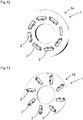
- the recording is according to FIGS. 12 and 13 realized so that multiple orientations of the individual distance sensors are possible, each of which is compatible with the hedging concept.
Landscapes
- Engineering & Computer Science (AREA)
- General Engineering & Computer Science (AREA)
- Mechanical Engineering (AREA)
- Robotics (AREA)
- Radar, Positioning & Navigation (AREA)
- Remote Sensing (AREA)
- Manipulator (AREA)
Applications Claiming Priority (1)
| Application Number | Priority Date | Filing Date | Title |
|---|---|---|---|
| DE102018113361.8A DE102018113361B4 (de) | 2018-06-05 | 2018-06-05 | Sensorsystem mit optoelektronischen Distanzsensoren |
Publications (2)
| Publication Number | Publication Date |
|---|---|
| EP3578324A1 true EP3578324A1 (fr) | 2019-12-11 |
| EP3578324B1 EP3578324B1 (fr) | 2020-09-09 |
Family
ID=66483949
Family Applications (1)
| Application Number | Title | Priority Date | Filing Date |
|---|---|---|---|
| EP19173862.4A Active EP3578324B1 (fr) | 2018-06-05 | 2019-05-10 | Système de détecteurs pourvu de détecteurs de distance optoélectroniques |
Country Status (3)
| Country | Link |
|---|---|
| EP (1) | EP3578324B1 (fr) |
| DE (1) | DE102018113361B4 (fr) |
| DK (1) | DK3578324T3 (fr) |
Cited By (1)
| Publication number | Priority date | Publication date | Assignee | Title |
|---|---|---|---|---|
| EP3875228A1 (fr) * | 2020-03-06 | 2021-09-08 | Sick Ag | Système de surveillance d'une zone de danger sur une partie mobile de machine |
Families Citing this family (2)
| Publication number | Priority date | Publication date | Assignee | Title |
|---|---|---|---|---|
| EP4706893A1 (fr) * | 2024-09-04 | 2026-03-11 | Roundpeg Technologies Gmbh | Couvercle de capteur pouvant être monté pour robot |
| DE102024133528B3 (de) * | 2024-11-15 | 2026-01-22 | Sick Ag | System, Verarbeitungsvorrichtung, Verwendung eines Systems und Verfahren zur Gesten-basierten Steuerung eines Industrieroboters mit einem beweglichen Abschnitt |
Citations (5)
| Publication number | Priority date | Publication date | Assignee | Title |
|---|---|---|---|---|
| DE102013020596A1 (de) * | 2013-12-13 | 2015-06-18 | Daimler Ag | Arbeitsstation und Verfahren zum Durchführen wenigstens eines Arbeitsschritts, insbesondere zum Herstellen eines Kraftwagens |
| DE102015112656A1 (de) | 2015-07-31 | 2017-02-02 | Sick Ag | Distanzsensor |
| DE102015216659A1 (de) * | 2015-09-01 | 2017-03-02 | Siemens Aktiengesellschaft | Vorrichtung zur Anbindung an einen Roboter |
| WO2017036732A1 (fr) * | 2015-09-01 | 2017-03-09 | Siemens Aktiengesellschaft | Dispositif de connexion à un robot |
| DE102017105999B3 (de) * | 2017-03-21 | 2018-03-01 | Sick Ag | Sensorsystem für einen mehrgliedrigen Roboter |
Family Cites Families (3)
| Publication number | Priority date | Publication date | Assignee | Title |
|---|---|---|---|---|
| US5777267A (en) * | 1996-06-28 | 1998-07-07 | Abb Flexible Automation, Inc. | Harness assembly to provide signals to end effector |
| DE102008063680A1 (de) * | 2008-10-10 | 2010-04-15 | Abb Ag | Verfahren zum Einlernen (Teachen) eines Industrieroboters sowie ein entsprechend ausgestatteter Industrieroboter |
| DE102013019869B4 (de) * | 2013-11-28 | 2022-01-13 | Abb Schweiz Ag | Roboterarm mit Eingabemodul |
-
2018
- 2018-06-05 DE DE102018113361.8A patent/DE102018113361B4/de not_active Expired - Fee Related
-
2019
- 2019-05-10 EP EP19173862.4A patent/EP3578324B1/fr active Active
- 2019-05-10 DK DK19173862.4T patent/DK3578324T3/da active
Patent Citations (5)
| Publication number | Priority date | Publication date | Assignee | Title |
|---|---|---|---|---|
| DE102013020596A1 (de) * | 2013-12-13 | 2015-06-18 | Daimler Ag | Arbeitsstation und Verfahren zum Durchführen wenigstens eines Arbeitsschritts, insbesondere zum Herstellen eines Kraftwagens |
| DE102015112656A1 (de) | 2015-07-31 | 2017-02-02 | Sick Ag | Distanzsensor |
| DE102015216659A1 (de) * | 2015-09-01 | 2017-03-02 | Siemens Aktiengesellschaft | Vorrichtung zur Anbindung an einen Roboter |
| WO2017036732A1 (fr) * | 2015-09-01 | 2017-03-09 | Siemens Aktiengesellschaft | Dispositif de connexion à un robot |
| DE102017105999B3 (de) * | 2017-03-21 | 2018-03-01 | Sick Ag | Sensorsystem für einen mehrgliedrigen Roboter |
Cited By (2)
| Publication number | Priority date | Publication date | Assignee | Title |
|---|---|---|---|---|
| EP3875228A1 (fr) * | 2020-03-06 | 2021-09-08 | Sick Ag | Système de surveillance d'une zone de danger sur une partie mobile de machine |
| US11738460B2 (en) | 2020-03-06 | 2023-08-29 | Sick Ag | System |
Also Published As
| Publication number | Publication date |
|---|---|
| EP3578324B1 (fr) | 2020-09-09 |
| DE102018113361A1 (de) | 2019-12-05 |
| DK3578324T3 (da) | 2020-11-02 |
| DE102018113361B4 (de) | 2020-12-03 |
Similar Documents
| Publication | Publication Date | Title |
|---|---|---|
| EP3136127B1 (fr) | Capteur telemetrique et procede comprenant un capteur telemetrique | |
| EP2989369B1 (fr) | Dispositif et procédé de sécurisation d'une machine travaillant de manière automatisée | |
| DE102019110882B4 (de) | Absichern eines beweglichen Maschinenteils | |
| DE202019102935U1 (de) | Sicherheitseinrichtung für Werkzeugmaschinen | |
| EP0306768A2 (fr) | Méthode et dispositif pour protéger un véhicule ou appareil mobile dans l'espace | |
| EP3578324B1 (fr) | Système de détecteurs pourvu de détecteurs de distance optoélectroniques | |
| DE3527063C1 (de) | Verfahren und Vorrichtung zum Schutz eines beweglichen,langgestreckten Maschinenteils | |
| EP4124789B1 (fr) | Fixation d'une pièce de machine mobile | |
| EP3875228B1 (fr) | Système de surveillance d'une zone de danger sur une partie mobile de machine | |
| DE102017113392B4 (de) | Vorrichtung zur Sicherheitssteuerung einer Maschine | |
| DE102017103568C5 (de) | Sensor und Verfahren zur Erfassung von Objekten | |
| DE202008016093U1 (de) | Überwachungssensor | |
| WO2020011337A1 (fr) | Dispositif de travail muni d'un robot monté sous table | |
| EP2395372A1 (fr) | Scanner de sécurité | |
| EP3578867B1 (fr) | Système de détecteurs pourvu de détecteurs de distance optoélectroniques | |
| DE202017100522U1 (de) | Überwachungseinrichtung | |
| DE102017101905B4 (de) | Überwachungseinrichtung | |
| DE102017119149A1 (de) | Verfahren zur berührungslosen Erfassung relativ zueinander bewegter Objekte und Sensoreinrichtung | |
| DE102018113362B4 (de) | Sensorsystem mit optoelektronischen Distanzsensormodulen | |
| EP3597983B1 (fr) | Système de capteur et module de capteur de distance | |
| DE202020101253U1 (de) | System | |
| EP3640522B1 (fr) | Dispositif de surveillance | |
| DE102017119283B4 (de) | Sensorsystem | |
| DE202017103611U1 (de) | Vorrichtung zur Sicherheitssteuerung einer Maschine | |
| DE102023120220B4 (de) | Sicherheitssystem zur Absicherung eines Aktionsbereichs einer Produktionsanlage |
Legal Events
| Date | Code | Title | Description |
|---|---|---|---|
| PUAI | Public reference made under article 153(3) epc to a published international application that has entered the european phase |
Free format text: ORIGINAL CODE: 0009012 |
|
| STAA | Information on the status of an ep patent application or granted ep patent |
Free format text: STATUS: THE APPLICATION HAS BEEN PUBLISHED |
|
| AK | Designated contracting states |
Kind code of ref document: A1 Designated state(s): AL AT BE BG CH CY CZ DE DK EE ES FI FR GB GR HR HU IE IS IT LI LT LU LV MC MK MT NL NO PL PT RO RS SE SI SK SM TR |
|
| AX | Request for extension of the european patent |
Extension state: BA ME |
|
| STAA | Information on the status of an ep patent application or granted ep patent |
Free format text: STATUS: REQUEST FOR EXAMINATION WAS MADE |
|
| RAP1 | Party data changed (applicant data changed or rights of an application transferred) |
Owner name: SICK AG |
|
| 17P | Request for examination filed |
Effective date: 20200211 |
|
| RBV | Designated contracting states (corrected) |
Designated state(s): AL AT BE BG CH CY CZ DE DK EE ES FI FR GB GR HR HU IE IS IT LI LT LU LV MC MK MT NL NO PL PT RO RS SE SI SK SM TR |
|
| RIC1 | Information provided on ipc code assigned before grant |
Ipc: B25J 15/00 20060101ALN20200417BHEP Ipc: F16P 3/14 20060101ALI20200417BHEP Ipc: B25J 19/06 20060101AFI20200417BHEP Ipc: B25J 19/02 20060101ALI20200417BHEP |
|
| GRAP | Despatch of communication of intention to grant a patent |
Free format text: ORIGINAL CODE: EPIDOSNIGR1 |
|
| STAA | Information on the status of an ep patent application or granted ep patent |
Free format text: STATUS: GRANT OF PATENT IS INTENDED |
|
| RIC1 | Information provided on ipc code assigned before grant |
Ipc: B25J 15/00 20060101ALN20200514BHEP Ipc: F16P 3/14 20060101ALI20200514BHEP Ipc: B25J 19/02 20060101ALI20200514BHEP Ipc: B25J 19/06 20060101AFI20200514BHEP |
|
| INTG | Intention to grant announced |
Effective date: 20200604 |
|
| RIN1 | Information on inventor provided before grant (corrected) |
Inventor name: WEBER, BENEDIKT Inventor name: STEINKEMPER, HEIKO Inventor name: SCHOTT, MICHAEL Inventor name: GEBAUER, JENS Inventor name: RAMACHANDRA, SANKETH Inventor name: HOFMANN, CHRISTOPH |
|
| GRAS | Grant fee paid |
Free format text: ORIGINAL CODE: EPIDOSNIGR3 |
|
| GRAA | (expected) grant |
Free format text: ORIGINAL CODE: 0009210 |
|
| STAA | Information on the status of an ep patent application or granted ep patent |
Free format text: STATUS: THE PATENT HAS BEEN GRANTED |
|
| AK | Designated contracting states |
Kind code of ref document: B1 Designated state(s): AL AT BE BG CH CY CZ DE DK EE ES FI FR GB GR HR HU IE IS IT LI LT LU LV MC MK MT NL NO PL PT RO RS SE SI SK SM TR |
|
| REG | Reference to a national code |
Ref country code: GB Ref legal event code: FG4D Free format text: NOT ENGLISH |
|
| REG | Reference to a national code |
Ref country code: AT Ref legal event code: REF Ref document number: 1311000 Country of ref document: AT Kind code of ref document: T Effective date: 20200915 Ref country code: CH Ref legal event code: EP |
|
| REG | Reference to a national code |
Ref country code: IE Ref legal event code: FG4D Free format text: LANGUAGE OF EP DOCUMENT: GERMAN |
|
| REG | Reference to a national code |
Ref country code: DE Ref legal event code: R096 Ref document number: 502019000201 Country of ref document: DE |
|
| REG | Reference to a national code |
Ref country code: DK Ref legal event code: T3 Effective date: 20201026 |
|
| REG | Reference to a national code |
Ref country code: LT Ref legal event code: MG4D |
|
| PG25 | Lapsed in a contracting state [announced via postgrant information from national office to epo] |
Ref country code: HR Free format text: LAPSE BECAUSE OF FAILURE TO SUBMIT A TRANSLATION OF THE DESCRIPTION OR TO PAY THE FEE WITHIN THE PRESCRIBED TIME-LIMIT Effective date: 20200909 Ref country code: BG Free format text: LAPSE BECAUSE OF FAILURE TO SUBMIT A TRANSLATION OF THE DESCRIPTION OR TO PAY THE FEE WITHIN THE PRESCRIBED TIME-LIMIT Effective date: 20201209 Ref country code: GR Free format text: LAPSE BECAUSE OF FAILURE TO SUBMIT A TRANSLATION OF THE DESCRIPTION OR TO PAY THE FEE WITHIN THE PRESCRIBED TIME-LIMIT Effective date: 20201210 Ref country code: LT Free format text: LAPSE BECAUSE OF FAILURE TO SUBMIT A TRANSLATION OF THE DESCRIPTION OR TO PAY THE FEE WITHIN THE PRESCRIBED TIME-LIMIT Effective date: 20200909 Ref country code: SE Free format text: LAPSE BECAUSE OF FAILURE TO SUBMIT A TRANSLATION OF THE DESCRIPTION OR TO PAY THE FEE WITHIN THE PRESCRIBED TIME-LIMIT Effective date: 20200909 Ref country code: NO Free format text: LAPSE BECAUSE OF FAILURE TO SUBMIT A TRANSLATION OF THE DESCRIPTION OR TO PAY THE FEE WITHIN THE PRESCRIBED TIME-LIMIT Effective date: 20201209 Ref country code: FI Free format text: LAPSE BECAUSE OF FAILURE TO SUBMIT A TRANSLATION OF THE DESCRIPTION OR TO PAY THE FEE WITHIN THE PRESCRIBED TIME-LIMIT Effective date: 20200909 |
|
| REG | Reference to a national code |
Ref country code: NL Ref legal event code: MP Effective date: 20200909 |
|
| PG25 | Lapsed in a contracting state [announced via postgrant information from national office to epo] |
Ref country code: RS Free format text: LAPSE BECAUSE OF FAILURE TO SUBMIT A TRANSLATION OF THE DESCRIPTION OR TO PAY THE FEE WITHIN THE PRESCRIBED TIME-LIMIT Effective date: 20200909 Ref country code: LV Free format text: LAPSE BECAUSE OF FAILURE TO SUBMIT A TRANSLATION OF THE DESCRIPTION OR TO PAY THE FEE WITHIN THE PRESCRIBED TIME-LIMIT Effective date: 20200909 Ref country code: PL Free format text: LAPSE BECAUSE OF FAILURE TO SUBMIT A TRANSLATION OF THE DESCRIPTION OR TO PAY THE FEE WITHIN THE PRESCRIBED TIME-LIMIT Effective date: 20200909 |
|
| PG25 | Lapsed in a contracting state [announced via postgrant information from national office to epo] |
Ref country code: SM Free format text: LAPSE BECAUSE OF FAILURE TO SUBMIT A TRANSLATION OF THE DESCRIPTION OR TO PAY THE FEE WITHIN THE PRESCRIBED TIME-LIMIT Effective date: 20200909 Ref country code: PT Free format text: LAPSE BECAUSE OF FAILURE TO SUBMIT A TRANSLATION OF THE DESCRIPTION OR TO PAY THE FEE WITHIN THE PRESCRIBED TIME-LIMIT Effective date: 20210111 Ref country code: RO Free format text: LAPSE BECAUSE OF FAILURE TO SUBMIT A TRANSLATION OF THE DESCRIPTION OR TO PAY THE FEE WITHIN THE PRESCRIBED TIME-LIMIT Effective date: 20200909 Ref country code: CZ Free format text: LAPSE BECAUSE OF FAILURE TO SUBMIT A TRANSLATION OF THE DESCRIPTION OR TO PAY THE FEE WITHIN THE PRESCRIBED TIME-LIMIT Effective date: 20200909 Ref country code: EE Free format text: LAPSE BECAUSE OF FAILURE TO SUBMIT A TRANSLATION OF THE DESCRIPTION OR TO PAY THE FEE WITHIN THE PRESCRIBED TIME-LIMIT Effective date: 20200909 |
|
| PG25 | Lapsed in a contracting state [announced via postgrant information from national office to epo] |
Ref country code: IS Free format text: LAPSE BECAUSE OF FAILURE TO SUBMIT A TRANSLATION OF THE DESCRIPTION OR TO PAY THE FEE WITHIN THE PRESCRIBED TIME-LIMIT Effective date: 20210109 Ref country code: AL Free format text: LAPSE BECAUSE OF FAILURE TO SUBMIT A TRANSLATION OF THE DESCRIPTION OR TO PAY THE FEE WITHIN THE PRESCRIBED TIME-LIMIT Effective date: 20200909 Ref country code: ES Free format text: LAPSE BECAUSE OF FAILURE TO SUBMIT A TRANSLATION OF THE DESCRIPTION OR TO PAY THE FEE WITHIN THE PRESCRIBED TIME-LIMIT Effective date: 20200909 |
|
| REG | Reference to a national code |
Ref country code: DE Ref legal event code: R097 Ref document number: 502019000201 Country of ref document: DE |
|
| PG25 | Lapsed in a contracting state [announced via postgrant information from national office to epo] |
Ref country code: SK Free format text: LAPSE BECAUSE OF FAILURE TO SUBMIT A TRANSLATION OF THE DESCRIPTION OR TO PAY THE FEE WITHIN THE PRESCRIBED TIME-LIMIT Effective date: 20200909 |
|
| PLBE | No opposition filed within time limit |
Free format text: ORIGINAL CODE: 0009261 |
|
| STAA | Information on the status of an ep patent application or granted ep patent |
Free format text: STATUS: NO OPPOSITION FILED WITHIN TIME LIMIT |
|
| 26N | No opposition filed |
Effective date: 20210610 |
|
| PG25 | Lapsed in a contracting state [announced via postgrant information from national office to epo] |
Ref country code: IT Free format text: LAPSE BECAUSE OF FAILURE TO SUBMIT A TRANSLATION OF THE DESCRIPTION OR TO PAY THE FEE WITHIN THE PRESCRIBED TIME-LIMIT Effective date: 20200909 |
|
| PG25 | Lapsed in a contracting state [announced via postgrant information from national office to epo] |
Ref country code: LU Free format text: LAPSE BECAUSE OF NON-PAYMENT OF DUE FEES Effective date: 20210510 Ref country code: MC Free format text: LAPSE BECAUSE OF FAILURE TO SUBMIT A TRANSLATION OF THE DESCRIPTION OR TO PAY THE FEE WITHIN THE PRESCRIBED TIME-LIMIT Effective date: 20200909 |
|
| REG | Reference to a national code |
Ref country code: BE Ref legal event code: MM Effective date: 20210531 |
|
| PG25 | Lapsed in a contracting state [announced via postgrant information from national office to epo] |
Ref country code: IE Free format text: LAPSE BECAUSE OF NON-PAYMENT OF DUE FEES Effective date: 20210510 |
|
| PG25 | Lapsed in a contracting state [announced via postgrant information from national office to epo] |
Ref country code: FR Free format text: LAPSE BECAUSE OF NON-PAYMENT OF DUE FEES Effective date: 20210531 |
|
| PG25 | Lapsed in a contracting state [announced via postgrant information from national office to epo] |
Ref country code: BE Free format text: LAPSE BECAUSE OF NON-PAYMENT OF DUE FEES Effective date: 20210531 |
|
| REG | Reference to a national code |
Ref country code: CH Ref legal event code: PL |
|
| PG25 | Lapsed in a contracting state [announced via postgrant information from national office to epo] |
Ref country code: LI Free format text: LAPSE BECAUSE OF NON-PAYMENT OF DUE FEES Effective date: 20220531 Ref country code: CH Free format text: LAPSE BECAUSE OF NON-PAYMENT OF DUE FEES Effective date: 20220531 |
|
| PG25 | Lapsed in a contracting state [announced via postgrant information from national office to epo] |
Ref country code: NL Free format text: LAPSE BECAUSE OF NON-PAYMENT OF DUE FEES Effective date: 20200923 Ref country code: CY Free format text: LAPSE BECAUSE OF FAILURE TO SUBMIT A TRANSLATION OF THE DESCRIPTION OR TO PAY THE FEE WITHIN THE PRESCRIBED TIME-LIMIT Effective date: 20200909 |
|
| PG25 | Lapsed in a contracting state [announced via postgrant information from national office to epo] |
Ref country code: HU Free format text: LAPSE BECAUSE OF FAILURE TO SUBMIT A TRANSLATION OF THE DESCRIPTION OR TO PAY THE FEE WITHIN THE PRESCRIBED TIME-LIMIT; INVALID AB INITIO Effective date: 20190510 |
|
| PG25 | Lapsed in a contracting state [announced via postgrant information from national office to epo] |
Ref country code: SI Free format text: LAPSE BECAUSE OF FAILURE TO SUBMIT A TRANSLATION OF THE DESCRIPTION OR TO PAY THE FEE WITHIN THE PRESCRIBED TIME-LIMIT Effective date: 20200909 |
|
| GBPC | Gb: european patent ceased through non-payment of renewal fee |
Effective date: 20230510 |
|
| PG25 | Lapsed in a contracting state [announced via postgrant information from national office to epo] |
Ref country code: MK Free format text: LAPSE BECAUSE OF FAILURE TO SUBMIT A TRANSLATION OF THE DESCRIPTION OR TO PAY THE FEE WITHIN THE PRESCRIBED TIME-LIMIT Effective date: 20200909 Ref country code: GB Free format text: LAPSE BECAUSE OF NON-PAYMENT OF DUE FEES Effective date: 20230510 |
|
| PG25 | Lapsed in a contracting state [announced via postgrant information from national office to epo] |
Ref country code: MT Free format text: LAPSE BECAUSE OF FAILURE TO SUBMIT A TRANSLATION OF THE DESCRIPTION OR TO PAY THE FEE WITHIN THE PRESCRIBED TIME-LIMIT Effective date: 20200909 |
|
| PGFP | Annual fee paid to national office [announced via postgrant information from national office to epo] |
Ref country code: DE Payment date: 20250519 Year of fee payment: 7 |
|
| PGFP | Annual fee paid to national office [announced via postgrant information from national office to epo] |
Ref country code: DK Payment date: 20250521 Year of fee payment: 7 |
|
| REG | Reference to a national code |
Ref country code: AT Ref legal event code: MM01 Ref document number: 1311000 Country of ref document: AT Kind code of ref document: T Effective date: 20240510 |
|
| PG25 | Lapsed in a contracting state [announced via postgrant information from national office to epo] |
Ref country code: AT Free format text: LAPSE BECAUSE OF NON-PAYMENT OF DUE FEES Effective date: 20240510 |
|
| PG25 | Lapsed in a contracting state [announced via postgrant information from national office to epo] |
Ref country code: TR Free format text: LAPSE BECAUSE OF FAILURE TO SUBMIT A TRANSLATION OF THE DESCRIPTION OR TO PAY THE FEE WITHIN THE PRESCRIBED TIME-LIMIT Effective date: 20200909 |
|
| PGFP | Annual fee paid to national office [announced via postgrant information from national office to epo] |
Ref country code: AT Payment date: 20260410 Year of fee payment: 5 |