EP3578366A1 - Verfahren zur herstellung einer fahrzeugverkleidung mit einem bedruckten dekorativen teil, verkleidung mit bedrucktem dekorativem teil und system zur durchführung des verfahrens - Google Patents
Verfahren zur herstellung einer fahrzeugverkleidung mit einem bedruckten dekorativen teil, verkleidung mit bedrucktem dekorativem teil und system zur durchführung des verfahrens Download PDFInfo
- Publication number
- EP3578366A1 EP3578366A1 EP18717968.4A EP18717968A EP3578366A1 EP 3578366 A1 EP3578366 A1 EP 3578366A1 EP 18717968 A EP18717968 A EP 18717968A EP 3578366 A1 EP3578366 A1 EP 3578366A1
- Authority
- EP
- European Patent Office
- Prior art keywords
- trim
- procedure
- exterior face
- coating
- pass
- Prior art date
- Legal status (The legal status is an assumption and is not a legal conclusion. Google has not performed a legal analysis and makes no representation as to the accuracy of the status listed.)
- Withdrawn
Links
- 238000000034 method Methods 0.000 title claims abstract description 87
- 238000004519 manufacturing process Methods 0.000 title claims abstract description 23
- 238000000576 coating method Methods 0.000 claims abstract description 67
- 239000011248 coating agent Substances 0.000 claims abstract description 64
- 238000007639 printing Methods 0.000 claims abstract description 35
- 238000007641 inkjet printing Methods 0.000 claims abstract description 29
- 238000005299 abrasion Methods 0.000 claims abstract description 19
- 238000012360 testing method Methods 0.000 claims description 24
- 239000002966 varnish Substances 0.000 claims description 23
- 239000000463 material Substances 0.000 claims description 20
- 229920003229 poly(methyl methacrylate) Polymers 0.000 claims description 14
- 239000004926 polymethyl methacrylate Substances 0.000 claims description 14
- 238000001746 injection moulding Methods 0.000 claims description 8
- 230000003287 optical effect Effects 0.000 claims description 7
- 238000013461 design Methods 0.000 claims description 6
- 229920000515 polycarbonate Polymers 0.000 claims description 6
- 239000004417 polycarbonate Substances 0.000 claims description 6
- 239000012815 thermoplastic material Substances 0.000 claims description 6
- 239000004676 acrylonitrile butadiene styrene Substances 0.000 claims description 5
- 239000000203 mixture Substances 0.000 claims description 5
- VYPSYNLAJGMNEJ-UHFFFAOYSA-N Silicium dioxide Chemical class O=[Si]=O VYPSYNLAJGMNEJ-UHFFFAOYSA-N 0.000 claims description 4
- 150000001252 acrylic acid derivatives Chemical class 0.000 claims description 4
- 229920002877 acrylic styrene acrylonitrile Polymers 0.000 claims description 4
- 238000004140 cleaning Methods 0.000 claims description 4
- 238000006073 displacement reaction Methods 0.000 claims description 4
- 238000002203 pretreatment Methods 0.000 claims description 4
- 229920006942 ABS/PC Polymers 0.000 claims description 2
- YAAQEISEHDUIFO-UHFFFAOYSA-N C=CC#N.OC(=O)C=CC=CC1=CC=CC=C1 Chemical compound C=CC#N.OC(=O)C=CC=CC1=CC=CC=C1 YAAQEISEHDUIFO-UHFFFAOYSA-N 0.000 claims description 2
- -1 Polybutylene Terephthalate Polymers 0.000 claims description 2
- XECAHXYUAAWDEL-UHFFFAOYSA-N acrylonitrile butadiene styrene Chemical compound C=CC=C.C=CC#N.C=CC1=CC=CC=C1 XECAHXYUAAWDEL-UHFFFAOYSA-N 0.000 claims description 2
- 229920000122 acrylonitrile butadiene styrene Polymers 0.000 claims description 2
- 229920001707 polybutylene terephthalate Polymers 0.000 claims description 2
- 238000007493 shaping process Methods 0.000 claims description 2
- 229920001169 thermoplastic Polymers 0.000 abstract description 3
- 239000004416 thermosoftening plastic Substances 0.000 abstract description 3
- 239000000758 substrate Substances 0.000 description 14
- 239000003973 paint Substances 0.000 description 11
- 238000001723 curing Methods 0.000 description 8
- 230000006870 function Effects 0.000 description 7
- 238000007591 painting process Methods 0.000 description 5
- 239000000243 solution Substances 0.000 description 5
- 230000000694 effects Effects 0.000 description 4
- 238000005516 engineering process Methods 0.000 description 4
- 238000002347 injection Methods 0.000 description 4
- 239000007924 injection Substances 0.000 description 4
- 230000006978 adaptation Effects 0.000 description 3
- 230000008901 benefit Effects 0.000 description 3
- 230000007547 defect Effects 0.000 description 3
- 239000012530 fluid Substances 0.000 description 3
- 238000009434 installation Methods 0.000 description 3
- 238000010422 painting Methods 0.000 description 3
- 230000009993 protective function Effects 0.000 description 3
- 238000005507 spraying Methods 0.000 description 3
- 238000012546 transfer Methods 0.000 description 3
- 230000016776 visual perception Effects 0.000 description 3
- 238000010586 diagram Methods 0.000 description 2
- 238000011156 evaluation Methods 0.000 description 2
- 238000007654 immersion Methods 0.000 description 2
- 230000010354 integration Effects 0.000 description 2
- 238000005259 measurement Methods 0.000 description 2
- 230000007246 mechanism Effects 0.000 description 2
- 239000002245 particle Substances 0.000 description 2
- 230000008569 process Effects 0.000 description 2
- 230000001739 rebound effect Effects 0.000 description 2
- 230000009467 reduction Effects 0.000 description 2
- 238000006748 scratching Methods 0.000 description 2
- 230000002393 scratching effect Effects 0.000 description 2
- 238000011282 treatment Methods 0.000 description 2
- 230000000007 visual effect Effects 0.000 description 2
- 238000009825 accumulation Methods 0.000 description 1
- 230000009471 action Effects 0.000 description 1
- 230000015556 catabolic process Effects 0.000 description 1
- 238000001311 chemical methods and process Methods 0.000 description 1
- 230000000295 complement effect Effects 0.000 description 1
- 230000001143 conditioned effect Effects 0.000 description 1
- 238000007796 conventional method Methods 0.000 description 1
- 238000003851 corona treatment Methods 0.000 description 1
- 230000002950 deficient Effects 0.000 description 1
- 238000006731 degradation reaction Methods 0.000 description 1
- 230000009977 dual effect Effects 0.000 description 1
- 230000007613 environmental effect Effects 0.000 description 1
- 239000011521 glass Substances 0.000 description 1
- 239000000976 ink Substances 0.000 description 1
- 239000007788 liquid Substances 0.000 description 1
- 238000013178 mathematical model Methods 0.000 description 1
- 238000000465 moulding Methods 0.000 description 1
- 230000008447 perception Effects 0.000 description 1
- 238000009832 plasma treatment Methods 0.000 description 1
- 229920003023 plastic Polymers 0.000 description 1
- 239000004033 plastic Substances 0.000 description 1
- 230000001681 protective effect Effects 0.000 description 1
- 239000011347 resin Substances 0.000 description 1
- 229920005989 resin Polymers 0.000 description 1
- 238000000926 separation method Methods 0.000 description 1
- 238000001228 spectrum Methods 0.000 description 1
- 238000007592 spray painting technique Methods 0.000 description 1
- 238000001029 thermal curing Methods 0.000 description 1
- 238000005406 washing Methods 0.000 description 1
- XLYOFNOQVPJJNP-UHFFFAOYSA-N water Substances O XLYOFNOQVPJJNP-UHFFFAOYSA-N 0.000 description 1
Images




Classifications
-
- B—PERFORMING OPERATIONS; TRANSPORTING
- B41—PRINTING; LINING MACHINES; TYPEWRITERS; STAMPS
- B41J—TYPEWRITERS; SELECTIVE PRINTING MECHANISMS, i.e. MECHANISMS PRINTING OTHERWISE THAN FROM A FORME; CORRECTION OF TYPOGRAPHICAL ERRORS
- B41J3/00—Typewriters or selective printing or marking mechanisms characterised by the purpose for which they are constructed
- B41J3/407—Typewriters or selective printing or marking mechanisms characterised by the purpose for which they are constructed for marking on special material
- B41J3/4073—Printing on three-dimensional objects not being in sheet or web form, e.g. spherical or cubic objects
-
- B—PERFORMING OPERATIONS; TRANSPORTING
- B65—CONVEYING; PACKING; STORING; HANDLING THIN OR FILAMENTARY MATERIAL
- B65D—CONTAINERS FOR STORAGE OR TRANSPORT OF ARTICLES OR MATERIALS, e.g. BAGS, BARRELS, BOTTLES, BOXES, CANS, CARTONS, CRATES, DRUMS, JARS, TANKS, HOPPERS, FORWARDING CONTAINERS; ACCESSORIES, CLOSURES, OR FITTINGS THEREFOR; PACKAGING ELEMENTS; PACKAGES
- B65D11/00—Containers having bodies formed by interconnecting or uniting two or more rigid, or substantially rigid, components made wholly or mainly of plastics material
- B65D11/02—Containers having bodies formed by interconnecting or uniting two or more rigid, or substantially rigid, components made wholly or mainly of plastics material of curved cross-section
-
- B—PERFORMING OPERATIONS; TRANSPORTING
- B41—PRINTING; LINING MACHINES; TYPEWRITERS; STAMPS
- B41J—TYPEWRITERS; SELECTIVE PRINTING MECHANISMS, i.e. MECHANISMS PRINTING OTHERWISE THAN FROM A FORME; CORRECTION OF TYPOGRAPHICAL ERRORS
- B41J11/00—Devices or arrangements of selective printing mechanisms, e.g. ink-jet printers or thermal printers, for supporting or handling copy material in sheet or web form
- B41J11/0015—Devices or arrangements of selective printing mechanisms, e.g. ink-jet printers or thermal printers, for supporting or handling copy material in sheet or web form for treating before, during or after printing or for uniform coating or laminating the copy material before or after printing
-
- B—PERFORMING OPERATIONS; TRANSPORTING
- B41—PRINTING; LINING MACHINES; TYPEWRITERS; STAMPS
- B41J—TYPEWRITERS; SELECTIVE PRINTING MECHANISMS, i.e. MECHANISMS PRINTING OTHERWISE THAN FROM A FORME; CORRECTION OF TYPOGRAPHICAL ERRORS
- B41J3/00—Typewriters or selective printing or marking mechanisms characterised by the purpose for which they are constructed
- B41J3/407—Typewriters or selective printing or marking mechanisms characterised by the purpose for which they are constructed for marking on special material
-
- B—PERFORMING OPERATIONS; TRANSPORTING
- B60—VEHICLES IN GENERAL
- B60R—VEHICLES, VEHICLE FITTINGS, OR VEHICLE PARTS, NOT OTHERWISE PROVIDED FOR
- B60R13/00—Elements for body-finishing, identifying, or decorating; Arrangements or adaptations for advertising purposes
-
- B—PERFORMING OPERATIONS; TRANSPORTING
- B60—VEHICLES IN GENERAL
- B60R—VEHICLES, VEHICLE FITTINGS, OR VEHICLE PARTS, NOT OTHERWISE PROVIDED FOR
- B60R13/00—Elements for body-finishing, identifying, or decorating; Arrangements or adaptations for advertising purposes
- B60R13/04—External Ornamental or guard strips; Ornamental inscriptive devices thereon
-
- B—PERFORMING OPERATIONS; TRANSPORTING
- B65—CONVEYING; PACKING; STORING; HANDLING THIN OR FILAMENTARY MATERIAL
- B65D—CONTAINERS FOR STORAGE OR TRANSPORT OF ARTICLES OR MATERIALS, e.g. BAGS, BARRELS, BOTTLES, BOXES, CANS, CARTONS, CRATES, DRUMS, JARS, TANKS, HOPPERS, FORWARDING CONTAINERS; ACCESSORIES, CLOSURES, OR FITTINGS THEREFOR; PACKAGING ELEMENTS; PACKAGES
- B65D11/00—Containers having bodies formed by interconnecting or uniting two or more rigid, or substantially rigid, components made wholly or mainly of plastics material
- B65D11/18—Containers having bodies formed by interconnecting or uniting two or more rigid, or substantially rigid, components made wholly or mainly of plastics material collapsible, i.e. with walls hinged together or detachably connected
-
- B—PERFORMING OPERATIONS; TRANSPORTING
- B65—CONVEYING; PACKING; STORING; HANDLING THIN OR FILAMENTARY MATERIAL
- B65D—CONTAINERS FOR STORAGE OR TRANSPORT OF ARTICLES OR MATERIALS, e.g. BAGS, BARRELS, BOTTLES, BOXES, CANS, CARTONS, CRATES, DRUMS, JARS, TANKS, HOPPERS, FORWARDING CONTAINERS; ACCESSORIES, CLOSURES, OR FITTINGS THEREFOR; PACKAGING ELEMENTS; PACKAGES
- B65D43/00—Lids or covers for rigid or semi-rigid containers
- B65D43/14—Non-removable lids or covers
- B65D43/16—Non-removable lids or covers hinged for upward or downward movement
- B65D43/162—Non-removable lids or covers hinged for upward or downward movement the container, the lid and the hinge being made of one piece
-
- B—PERFORMING OPERATIONS; TRANSPORTING
- B05—SPRAYING OR ATOMISING IN GENERAL; APPLYING FLUENT MATERIALS TO SURFACES, IN GENERAL
- B05D—PROCESSES FOR APPLYING FLUENT MATERIALS TO SURFACES, IN GENERAL
- B05D1/00—Processes for applying liquids or other fluent materials
- B05D1/26—Processes for applying liquids or other fluent materials performed by applying the liquid or other fluent material from an outlet device in contact with, or almost in contact with, the surface
-
- B—PERFORMING OPERATIONS; TRANSPORTING
- B05—SPRAYING OR ATOMISING IN GENERAL; APPLYING FLUENT MATERIALS TO SURFACES, IN GENERAL
- B05D—PROCESSES FOR APPLYING FLUENT MATERIALS TO SURFACES, IN GENERAL
- B05D2201/00—Polymeric substrate or laminate
-
- B—PERFORMING OPERATIONS; TRANSPORTING
- B05—SPRAYING OR ATOMISING IN GENERAL; APPLYING FLUENT MATERIALS TO SURFACES, IN GENERAL
- B05D—PROCESSES FOR APPLYING FLUENT MATERIALS TO SURFACES, IN GENERAL
- B05D3/00—Pretreatment of surfaces to which liquids or other fluent materials are to be applied; After-treatment of applied coatings, e.g. intermediate treating of an applied coating preparatory to subsequent applications of liquids or other fluent materials
- B05D3/06—Pretreatment of surfaces to which liquids or other fluent materials are to be applied; After-treatment of applied coatings, e.g. intermediate treating of an applied coating preparatory to subsequent applications of liquids or other fluent materials by exposure to radiation
- B05D3/061—Pretreatment of surfaces to which liquids or other fluent materials are to be applied; After-treatment of applied coatings, e.g. intermediate treating of an applied coating preparatory to subsequent applications of liquids or other fluent materials by exposure to radiation using U.V.
- B05D3/065—After-treatment
- B05D3/067—Curing or cross-linking the coating
Definitions
- the invention relates to a procedure for manufacturing a trim component for a vehicle, the trim comprising a decorative part obtained by inkjet printing.
- the invention also relates to a system to carry out the procedure and a trim with a printed decorative part.
- trims In the automotive sector, components called trims, whose main function is to provide an aesthetic finish to a certain area of the vehicle, are known in the prior art. These trims may also implement certain additional functions which are not purely aesthetic.
- some trims installed in the door frame of the vehicle may be provided with a structural part and a decorative part, each of which is made out of a different material, such as, for example two thermoplastic materials suitable for the function of each part.
- the structural part acts as a mechanical support and may integrate additional functional elements, such as, for example, elements to secure the trim to the vehicle's bodywork and/or guiding elements for the door window.
- the decorative part is intended to hide the structural part, whereby it is visible from the exterior when the trim is installed on the vehicle. This decorative part provides an aesthetics that is attractive and in harmony with areas of the vehicle adjacent to the trim.
- a solution to obtain a trim with a high gloss finish and scratch and abrasion resistance consists in applying a coating to the trim by means of a subsequent painting of the shaped trim.
- the decorative part of these trims is made up of a layer of paint applied on a thermoplastic structural part, previously moulded by injection.
- the painting process can be carried out using conventional techniques, such as, for example, spray painting in paint booths.
- a paint booth is an isolated and conditioned space, designed to allow a surface to be painted with a high quality finish and under conditions that comply with prevailing environmental and safety regulations.
- booths are usually fitted with mechanisms, such as filters or water curtains, intended to eliminate contaminating particles and traces of paint that cannot be used and which does not adhere to the surface to be painted. Therefore, this type of facilities usually requires significant economic investment and its performance is not optimal.
- a common solution to provide the trim with a high gloss finish, without requiring a conventional painting process consists in making the decorative part out of a thermoplastic material that is capable of providing such glossy finish, such as, for example Polymethylmethacrylate (PMMA).
- PMMA Polymethylmethacrylate
- Different methods for the manufacture of trims with PMMA decorative parts are known in the prior art.
- One possible method, known as bi-material injection consists in injection moulding the PMMA decorative part over the structural part of the trim.
- the structural part is moulded with another thermoplastic material that is chemically compatible with PMMA such as, for example Acrylonitrile-Butadiene-Styrene (ABS).
- ABS Acrylonitrile-Butadiene-Styrene
- trims Another traditional alternative, for the manufacture of structural and decorative parts of this type of trims, consists in injection moulding the two parts independently and then proceeding to the assembly or connection of both parts to form the trim.
- trims with a PMMA finish and produced in accordance with the aforementioned procedures, are described in the patent application MX2009004266A and in the patent ES2313471T3 .
- these solutions to manufacture trims with a PMMA decorative part have the disadvantage of requiring several moulds and/or complex bi-material moulds, therefore the required facilities are usually expensive and difficult to handle.
- Another important limitation of the PMMA finish is that it provides insufficient scratch resistance under certain conditions.
- Inkjet printing is based on the controlled ejection of small drops of a certain liquid or fluid, through one or various print heads fitted with several injectors. The drops adhere to the surface of an object or substrate.
- This technology can be used with diverse types of inks, varnishes or other fluids, with different viscosities and on a variety of different substrates, mainly in the field of decorative printing although also in the field of functional printing.
- some applications that use the inkjet printing technique to apply a coating on a preformed flat plastic substrate are known in the prior art.
- the patent discloses a procedure for applying a resin coating, on a transparent flat substrate by means of inkjet printing.
- the substrate has reduced dimensions and is intended for the manufacture of a display screen or display for a mobile phone, calculator or similar.
- the invention ES2260466T3 aims to overcome the drawbacks of other traditional coating techniques via immersion or flow.
- the patent application describes a procedure for the application of a coating, on the surface of a preferably opaque substrate, by means of inkjet printing.
- This solution also aims to mitigate the problems inherent to conventional coating techniques by immersion, flow or spraying.
- the description of the patent application indicates that the coating is capable of providing the substrate with a finish that is resistant to abrasion and scratching, as well as a high gloss finish. To do so, a composition that is suitable for such purposes can be selected from diverse compositions known in the prior art.
- the WO2016128418A1 publication mentions that the substrate on which the coating is applied may be a component for a vehicle, such as, for example a trim. However, it does not explain how to resolve certain difficulties associated with the use of inkjet printing to obtain a trim with a quality finish in accordance with today's demands of the automotive sector.
- the present invention proposes a procedure for manufacturing trims with a coating or decorative part produced by means of inkjet printing, with an acceptable quality at an admissible cost.
- the procedure makes it possible to manufacture a trim, with a high gloss finish and scratch and abrasion resistance, which is able to pass quality tests of the automotive sector.
- the trim comprises a structural part with an exterior face.
- This exterior face is made up of a plurality of surfaces intended to remain visible from the exterior when the trim is installed on the vehicle.
- the surfaces extend along a longitudinal direction of the trim and are continuously arranged in an X direction in accordance with the width of the trim, wherein at least one of these surfaces has at least a slight curvature. Additionally, the exterior face also has at least a slight curvature in the longitudinal direction.
- the procedure according to the invention is characterised in that it comprises a first step, in which the structural part is manufactured by shaping a first material, and a subsequent second step, consisting in applying a coating of a second material on all of the surfaces of the exterior face.
- the coating is applied using the inkjet printing technique, by means of at least one fixed print head and in such a way that the structural part makes at least one pass with respect to the print head during printing.
- This pass is defined as a complete longitudinal displacement of the structural part with respect to the print head, in accordance with an at least slight three-dimensional curvilinear movement which allows for obtaining a uniform coating on the exterior face.
- the procedure of the invention provides the trim with a decorative part printed using the inkjet printing technology on a previously shaped or moulded structural part of the trim to form a piece in three dimensions.
- the printing is carried out directly on a non-flat substrate, made up of the plurality of surfaces of the exterior face, and on the whole of this non-flat substrate.
- the procedure comprises the prior to printing definition of an optimised three-dimensional path adapted to the geometry of the exterior face.
- trims are obtained with increased performance to scratching compared with conventional trims with a PMMA decorative part.
- the finish may be insufficient under certain conditions (for example after successive wash cycles of the vehicle). Obtaining a finish with a good scratch resistance is also of great importance due to the new functions implemented in the trims (such as antennas or electronic security locks), which involve an increasing degree of handling of these components by the user of the vehicle.
- the use of the inkjet printing technique also implies a better use of the coating material, in relation to conventional painting techniques, in such a way that the performance of the production process is increased.
- the transfer rate is defined as a percentage of paint that is deposited on the treated piece in relation to the total amount of paint applied by the treatment. It is estimated that in conventional painting processes via spraying in paint booths, a typical transfer rate may be around 20%, wherein the remaining percentage of paint is spread around the paint booth without the possibility of reusing it. In other words, there is a considerable loss of material that cannot be reused.
- the inkjet printing is a very precise technique which allows appropriate control of the area on which the printed material is applied, whereby high transfer rates of around 95% can be achieved.
- this printing technique also involves a reduction in facilities investment, compared with conventional painting techniques, such as the aforementioned spraying technique or compared with other coating techniques, such as coating by curtain or flow.
- the invention is also related to a system for the implementation of the procedure and it is also related to a trim for a vehicle with a decorative part made up of a surface coating applied by means of inkjet printing.
- the invention is related to a procedure for manufacturing trims for vehicles, for example, trims like those installed on the exterior of a vehicle to provide the vehicle with an aesthetically attractive finish.
- Figure 1 shows a front view of an embodiment for a trim or, more precisely, a pillar trim for the door frame of a vehicle, manufactured following the invention procedure. The figure shows the trim (1) in a vertical position as it is found when installed on the door frame of the vehicle.
- Figure 2 shows a rear view of the trim (1) of Figure 1 .
- the trim (1) comprises a structural part (2) with a main surface or exterior face (3) and an interior face (4).
- Figure 3 shows a profile view of the trim (1) of Figures 1 and 2 .
- the trim (1) is not flat along its longitudinal dimension but has a slight longitudinal curvature.
- Figure 4 shows a sectional view of the trim (1) in accordance with the AA cut marked in Figure 1 .
- the exterior face (3) is made up of a plurality of adjacent portions or surfaces (3a, 3b) continuously arranged in an X direction in accordance with the width of the trim (1). These surfaces (3a, 3b) are intended to remain visible from the exterior of the vehicle when the trim (1) is installed on the vehicle in the position shown in Figure 1 .
- the interior face (4) of the structural part (2) comprises surfaces which remain hidden from view when the trim (1) is installed on the vehicle.
- This interior face (4) may have a more complex geometry than the exterior face (3), being normally provided with several surfaces (4a, 4b, 4c) that may be substantially flat surfaces (4a), slightly curved surfaces(4b) or surfaces (4c) with pronounced curvatures or angles, forming protruding elements, protuberances, recesses or others. Both the exterior face (3) and the interior face (4) are delimited by a common contour (5), as illustrated in Figures 1 and 2 . Despite the fact that the geometry of the exterior face (3) is simpler than that the geometry of the interior face (4), the surfaces (3a, 3b) may have a different curvature or orientation, so that the exterior face (3) is not entirely flat, comprising substantially flat surfaces (3a) and surfaces (3b) with at least one slight curvature.
- the structural part (2) has two slightly curved sides or ends (6, 7).
- the exterior face (3) is particularly made up of a first curved surface (3b) arranged at the left end (6) of the structural part (2), followed by a substantially flat surface (3a) located in a central position, followed by a second curved surface (3b) arranged at the right end (7) of the structural part (2) and an additional final substantially flat surface (3a) with a short length.
- the exterior face (3) may have a different combination of surfaces (3a, 3b), with ends (6, 7) that may have more or less pronounced angles or elbows or additional substantially flat portions.
- the trim (1) manufactured in accordance with the invention procedure is a three-dimensional piece, with a slightly curved geometry and an external surface with curvature changes both in the longitudinal direction of the trim (1) and as well in the width X direction of the trim (1). These curvature changes define the surface of the exterior face (3) of the structural part (2) of the trim (1).
- the procedure according to the invention comprises a first step, consisting in manufacturing the structural part (2) of the trim (1), for example by means of injection moulding of a first thermoplastic material.
- the procedure is characterized in that it comprises a second step consisting in applying a coating of a second material, by means of inkjet printing on all of the surfaces (3a, 3b), for manufacturing a decorative part printed on the exterior face (3) of the structural part (2).
- the printing is carried out after the injection step of the structural part (2) and outside the injection mould.
- the exterior face (3) defined by the surfaces (3a, 3b) serves as a three-dimensional substrate on which the inkjet printing is carried out.
- the coating is applied by means of at least one fixed print head (12) in such a way that, during printing, the structural part (2) makes at least one pass with respect to the print head (12).
- This pass is defined as a full longitudinal displacement of the structural part (2) with respect to the print head (12), following a three-dimensional curvilinear movement that allows for a uniform finish on the exterior face (3).
- the trim (1) may optionally be connected to a movable support (13), controlled by an external drive (14), which transmits an at least slight three-dimensional curvilinear movement to the trim (1).
- the geometry of the trim (1) is relatively simple. Although it is a three-dimensional piece, the exterior face (3) is devoid of protuberances or sharp protruding elements.
- the use of the inkjet printing technology to obtain a uniform surface coating on the trim (1) presents certain difficulties. This is due to the fact that the longitudinal curvature and the presence of the curved surfaces (3b) of the exterior face (3) make the printing process difficult.
- the fixed print head (12) has a flat surface (15) which must face a three-dimensional surface for the application of the coating on the exterior face (3).
- the invention procedure allows for an adaptation to the curvature changes of the exterior face (3) providing a uniform and quality finish on both the flat surfaces (3a) and on the curved surfaces (3b).
- the procedure comprises a step prior to printing which consists in defining at least one optimised three-dimensional path (T1) in accordance with the particular geometry of the trim (1).
- the direction of this path (T1) may present deviations with respect to the contour (5) or with respect to the longitudinal profile of the exterior face (3).
- the structural part (2) makes a longitudinal pass in accordance with the previously calculated path (T1).
- the optimisation or adaptation of the path (T1) enables a confrontation between the exterior face (3) and the print head (12) so that a substantially constant distance D is maintained between them throughout the whole pass.
- the portion or area of the exterior face (3) that is being printed at each moment remains substantially parallel and close to the fixed print head (12), thus minimising certain undesired effects that may negatively affect the appearance of the finish, such as, for example the orange peel effect.
- Substantially constant herein means a variation in the distance D, between the print head (12) and the exterior face (3) and along the longitudinal pass, no longer than a small margin variation.
- Printing is carried out at a distance D within a tolerance range limited by the values (d- ⁇ d, d+ ⁇ d).
- This tolerance range defines a minimum distance D and a maximum distance D, so that the safety of the printing system components and the quality of the coating obtained are simultaneously guaranteed.
- the absolute value of the variation margin ⁇ d is lower than or equal to 1 mm. Therefore, with a parameter d chosen for the pass in accordance with path (T1) equal to 2.5 mm, the distance D between the print head (12) and the exterior face (3) will remain substantially constant within a range between 2.5 mm ⁇ 1 mm, or in other words, between 1.5 mm and 3.5 mm throughout the whole pass.
- the parameter d is within a range between 2 mm and 4 mm, so that the distance D between the print head (12) and the exterior face (3) will be within a preferred total tolerance range between 1 mm and 5 mm.
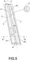
- the procedure comprises an additional step prior to printing which consists in defining at least one dividing curve (C) on the exterior face (3).
- This dividing curve (C) delimits two longitudinal sections or strips (F1, F2) of the exterior face (3).
- a single dividing curve (C) is defined that specifically delimits two strips (F1, F2) as shown schematically in Figures 5 and 6 .
- the dividing curve (C) does not have to match a symmetry line of the exterior face (3) and does not necessarily need to be parallel to the longitudinal portions of the contour (5) of the exterior face (3).
- Each of these longitudinal strips (F1, F2) is delimited by the dividing curve (C) and by the contour (5) of the exterior face (3).
- Printing in this case, comprises two non-simultaneous passes (P1, P2) for the application of the coating on both strips (F1, F2). Carrying out the printing in different passes allows for a better adaptation to the geometry of the exterior face (3).
- This embodiment of the invention has the additional advantage of allowing the exterior face (3) to be coated by means of a single print head (12) with a width shorter than the width of the trim (1).
- Commercial industrial printers are usually fitted with print heads with a typical width of around 65 or 70 mm.
- the trims may have a larger width, for example of up to 100 mm.
- two independent three-dimensional paths (T1, T2) that are specifically adapted to the geometry of each strip (F1, F2) are specifically defined prior to printing.
- the structural part (2) makes a first pass (P1) following the first path (T1) and then a second pass (P2) following the second path (T2), keeping the distance D between the exterior face (3) and the print head (12) substantially constant along both passes.
- the direction of the path (T2) is opposite to the direction of the path (T1).
- Opposite direction must herein be understood in the sense that during the first pass (P1) the coating is applied on the exterior face (3) from a lower end (8) towards an upper end (9) of the structural part (2), and during the second pass (P2) the coating is applied from the upper end (9) towards the lower end (8).
- the choice of paths (T1, T2) in opposite directions helps to optimise the performance of the procedure.
- a first strip between the left end (6) of the structural part (2) and the first dividing curve will be delimited, as well as a second central strip between the two dividing curves and a third strip between the second dividing curve and the right end (7).
- Printing in this case, comprises three non-simultaneous passes for the application of the coating on the three strips.
- This embodiment is advantageous because it enables a coating to be applied on a structural part (2) when it is not possible to maintain a distance D within the tolerance range (d- ⁇ d, d+ ⁇ d), for the whole of the exterior face (3) with only two passes, due to the geometry of the trim (1).
- This option allows for the coating of trims (1) with pronounced angles close to the contour (5) using the procedure according to the invention.
- the inkjet printing heads comprise a plurality of injectors through which the system ejects the drops of fluid to apply the coating.
- Printing is binary, whereby each injector may or may not be active (ejecting drops) in a given pass.
- each of the passes (P1, P2) there is a percentage of active injectors and a percentage of inactive injectors. This possibility is used, for example, in areas adjacent to the dividing curve (C), as illustrated schematically by shading in Figure 5 , in order to cover each strip (F1, F2) properly and make an adequate overlap of the two strips (F1, F2) along the dividing curve (C).
- the injectors that have remained inactive are discharged in order to avoid blockage problems.
- the print heads (12) can be positioned in parallel in the X direction so that the two of them cover the entire width of the trim (1).
- the print heads (12) print simultaneously and the structural part (2) carries out a single pass for the coating of the exterior face (3).
- This embodiment has the advantage of allowing an increase in the production speed.
- the two print heads (12) may be positioned in series in the longitudinal direction of the trim (1).
- the structural part (2) carries out two passes for the coating of the exterior face (3) and both print heads (12) print simultaneously at a faster speed compared to configurations with just one print head, also increasing the production speed in this case.
- FIG. 7 shows a block diagram of an embodiment of the system according to the invention.
- the system (10) comprises a inkjet printing unit (11), with at least one fixed print head (12) for the application of a coating on a trim (1) as shown in Figures 1 to 6 .
- the system (10) has the particularity of comprising a movable support (13) jointly connected to the trim (1) and controlled by an external drive (14).
- the movable support (13) is a light grip that enables the trim (1) to be secured and positioned under the print head (12) respecting the tolerance range defined for the procedure, or in other words, keeping a distance D between the exterior face (3) and the print head (12) that is equal to a design parameter d plus an absolute value variation margin ⁇ d lower than or equal to 1 mm.
- the structural part (2) of the trim (1) is produced via injection moulding.
- the trim (1) is connected to the movable support (13) and then after an optional pre-treatment phase, the drive (14) positions the movable support (13) in an initial situation under the print head (12), as schematically illustrated in Figure 7 .
- the separation between the flat surface (15) of the print head (12) and the exterior face (3) (non-flat substrate) is variable, due to the non-flat geometry of the exterior face (3).
- the movable support (13) moves forward and turns simultaneously, actuated by the drive (14), transmitting this three-dimensional curvilinear movement to the trim (1) based on paths, previously defined and adapted to the geometry of the exterior face (3).
- Control software coordinates the printing by the print head (12) and the movement of the movable support (13). In this way, it is possible to accurately control the downfall of the drops injected by the print head (12) on the exterior face (3) of the structural part (2). Maintaining a close and substantially constant distance D between the print head (12) and the exterior face (3) allows an adequate control of the downfall direction of the drops on the exterior face (3).
- the control software also allows for controlling the quantity and speed printing of the second material on the exterior face (3). For example, in configurations with two serial print heads (12), it is possible to control that each print head (12) ejects half of the material at dual speed, compared with configurations with just one print head (12).
- the second material used for the coating of the exterior face (3) is a transparent varnish.
- the composition of the varnish includes reactive acrylates and/or modified silica.
- the varnish To enable the varnish to pass through the print heads (12), its viscosity or density must be lower than that of other varnishes used in conventional airbrush painting processes, due to the fact that the outlet holes used are smaller.
- the application of this type of varnish according to the invention procedure provides the trim (1) with a glossy finish and enough scratch and abrasion resistance to pass quality automotive tests. These protective properties are achieved without the need to apply additional coatings, for example by means of chemical processes used to add protective functions to a printed substrate, as occurs in other applications known in the prior art.
- the procedure comprises the ultraviolet curing of the printed coating for the polymerisation of the varnish, enabling the subsequent handling of the varnished areas.
- varnishing via inkjet printing presents high performance and greater flexibility with respect to conventional varnishing techniques in booths.
- Printing minimizes a rebound effect that is typical in conventional varnishing processes.
- the rebound effect refers to a certain percentage of the varnish deposited on certain areas of the piece. Those areas do not require varnishing but their subsequent curing is still necessary to enable the piece to be handled.
- the undesired varnishing may occur in any area, particularly in areas of the trim with accessibility difficulties.
- the installation of curing lamps or additional devices is usually required, as well as their proper positioning and orientation in accordance with the specific geometry of each trim and each rebound area.
- the layout of the lamps must be readapted again, before subsequent curing other trims with other geometries and/or different rebound areas.
- the installation required for the curing of a varnished trim (1) by printing is less complex, less costly and more flexible, in comparison with the installation required for the curing of a trim varnished in accordance with traditional methods.
- the procedure optionally includes an additional pre-treatment step prior to the inkjet printing step.
- the structural part (2) of the trim (1) may be scoured after the injection moulding of the structural part (2), in order to eliminate dirt particles present on the surfaces of the trim (1), particularly on the surfaces (3a, 3b) of the structural part (2).
- Another possibility is to subject the surfaces (3a, 3b) to flame treatment, corona treatment or plasma treatment prior to printing. These or other optional pre-treatments are intended to increase the adhesion of the varnish to the surfaces (3a, 3b).
- the invention is also related to a trim (1) for a vehicle.
- the trim (1) comprises a structural part (2) with an exterior face (3).
- the exterior face (3) comprises a plurality adjacent surfaces (3a, 3b) intended to remain visible from the exterior of the vehicle when the trim (1) is installed on the vehicle.
- the surfaces (3a, 3b) extend longitudinally along the structural part (2) and are continuously arranged in the X direction, as in the embodiment of Figures 1 to 6 .
- the exterior face (3) has a slight longitudinal curvature and at least one of these surfaces (3b) has a slight curvature in the X direction.
- the trim (1) has the particularity of comprising a coating of a varnish, preferably transparent, applied on the whole of the surfaces (3a, 3b) by means of inkjet printing. This printed coating or layer is the decorative part of the trim (1) which combines an aesthetic function and a protective function of the structural part (2).
- the trim (1) has a high gloss finish and scratch and abrasion resistance in accordance with the requirements of the automotive sector.
- the trim according to the invention has a glossy surface finish with a uniform appearance.
- the perception of the appearance is a visual impression of an observer. This visual impression depends on the incident lighting and on the evaluated surface.
- the focus of the observer evaluating the appearance of a glossy surface may focus on the image reflected by the surface or on the surface itself.
- the evaluation of the reflected image defines the image quality or the reflection capacity of the surface, in terms of gloss, haze (milky appearance) and distinctness of image or DOI (which quantifies the loss of definition/contrast of the reflected image caused by the scattering of the incident light on fine structures).
- DOI distinctness of image
- the structure In glossy surfaces, the structure is perceived by the human eye as clear and dark waves with different sizes, because the discontinuity of the structure causes the light to reflect in different directions and the light straight reflected towards the eye of the observer is perceived as a clearer area.
- the visibility of these textures depends on their physical size, the observing distance and the reflected image quality.
- the visual perception of the waves is known as the "orange peel" effect or flow or levelling defects.
- Gloss is the visual perception of the amount of direct light reflected. Gloss meters refer to the amount of light reflected with reference to a black glass calibration pattern of 100 gloss units (GU). High gloss surfaces are considered to be those with a gloss value higher than 70 GU.
- the waviness of the automotive coatings usually oscillates between 0.1 mm to 30 mm wavelength.
- a WaveScan meter can be used to simulate the visual perception of this waviness.
- the device optically scans the waviness of the structure along a certain length.
- the measured signal is divided into frequency ranges, using several filters, generating various bands: Wa (0.1-0.3 mm), Wb (0.3 - 1 mm), Wc (1-3 mm), Wd (3-10 mm) and We (10-30 mm).
- Wa 0.1-0.3 mm
- Wb 0.3 - 1 mm
- Wc 1-3 mm
- Wd 3-10 mm
- We 10-30 mm
- a mathematical model or optical profile is obtained, which defines the structure spectrum.
- the optical profile represents the visibility of the waves in accordance with the wavelengths analysed and allows for determining which structure sizes are present in the coating.
- a relevant long wave LW range is defined (values of the optical profile generated by waves between 1.2 and 12 mm wavelength
- the invention procedure allows for obtaining a high gloss trim (1), with a preferred high gloss value on the exterior face (3) higher than 80 GU.
- the exterior face (3) has reduced orange peel whose optical profile, measured for example using a WaveScan device, has an LW value lower than 18.
- the procedure provides a basic range trim (1) which fulfils the quality requirements of the automotive sector.
- the LW value is lower than 15, obtaining an intermediate range trim (1).
- the LW value is lower than 10 obtaining a superior range trim (1).
- the gloss of the exterior face (3) is higher than 85 GU. Fulfilment of this requirement allows for complying with the quality tests for trims adequate for the integration of new additional functions, such as, for example, antennas or security mechanisms.
- the procedure of the invention produces a trim (1) with enough scratch and abrasion resistance to pass the usual quality tests according to common automotive standards. Some of these tests are referred to below.
- the exterior face (3) of the trim (1) has enough abrasion resistance to pass the cleaning brushes test.
- the test may be carried out using Elcometer 1720 equipment and complementary accessories. It is known that the paint or varnish coatings, applied on the exterior surfaces of a vehicle, may be damaged due to the successive effect of car wash brushes.
- the cleaning brushes test consists in subjecting the high gloss coating to the action of a rotating brush, equipped with synthetic bristles impregnated with an abrasive solution. The defect obtained is an optical dullness caused by the accumulation of scratches, comparable with the defect found in vehicles that often use washing facilities. The degradation of the tested surface is evaluated via the measurement of the loss of gloss.
- the test is passed by the trim (1) with a loss of gloss on the exterior face (3) lower than or equal to 10 GU, measured at a 20° angle.
- the exterior face (3) of the trim (1) also has a dry abrasion resistance in accordance with the usual requirements of the automotive sector.
- One test consists in rubbing the high gloss coating using a felt band that makes a back and forth movement. A total of 5,000 cycles are completed. The test may be carried out using a linear abrasion meter, such as the electronic Jarp Crockmeter.
- the test is passed by the trim (1) with a loss of gloss on the exterior face (3) lower than or equal to 5 GU, measured at a 20° angle.
- the trim (1) is able to pass the abrasion test, which is carried out using the same equipment but using a Velcro band during 10,000 cycles, also obtaining a loss of gloss lower than or equal to 5 GU. This requirement is necessary for trims (1) that implement the previously mentioned additional new functions.
- the exterior face (3) has enough scratch resistance to pass the sclerometer test.
- This test may be performed with an Erichsen 318 sclerometer, equipped with a tip that penetrates the tested surface and applies a gradual force that may cause scratches.
- the trim (1) is able to pass the sclerometer test with the following result: no marks or visible scratches are produced with an applied force lower than 3 Newton (N) and the coating does not become detached from the exterior face (3) with an applied force lower than 20 Newton (N).
- the coating of the trim(1) is obtained by means of printing an ultraviolet curable transparent varnish whose composition includes reactive acrylates and/or modified silica.
- the structural part (2) is manufactured by the injection moulding of a thermoplastic material, such as Acrylonitrile-Butadiene-Styrene (ABS), Acrylonitrile-Styrene-Acrylate (ASA), Acrylonitrile-Butadiene-Styrene /Polycarbonate (ABS/PC), Polycarbonate Polybutylene Terephthalate (PC-PBT), Polymethylmethacrylate (PMMA) or Polycarbonate (PC).
- ABS Acrylonitrile-Butadiene-Styrene
- ASA Acrylonitrile-Styrene-Acrylate
- ABS/PC Polycarbonate Polybutylene Terephthalate
- PC-PBT Polymethylmethacrylate
- PC Polycarbonate
- the invention also relates to a vehicle that comprises or incorporates any embodiment of the trim (1) according to the invention.
Landscapes
- Engineering & Computer Science (AREA)
- Mechanical Engineering (AREA)
- Manufacturing & Machinery (AREA)
- Vehicle Interior And Exterior Ornaments, Soundproofing, And Insulation (AREA)
- Application Of Or Painting With Fluid Materials (AREA)
Applications Claiming Priority (2)
| Application Number | Priority Date | Filing Date | Title |
|---|---|---|---|
| ES201730130A ES2677730B2 (es) | 2017-02-06 | 2017-02-06 | Procedimiento de fabricacion de un embellecedor con parte decorativa impresa para un vehiculo, sistema para la ejecucion del procedimiento y embellecedor con parte decorativa impresa. |
| PCT/ES2018/070081 WO2018142012A1 (es) | 2017-02-06 | 2018-02-02 | Procedimiento de fabricación de un embellecedor con parte decorativa impresa para un vehículo, embellecedor con parte decorativa impresa y sistema para la ejecución del procedimiento |
Publications (1)
| Publication Number | Publication Date |
|---|---|
| EP3578366A1 true EP3578366A1 (de) | 2019-12-11 |
Family
ID=61972550
Family Applications (1)
| Application Number | Title | Priority Date | Filing Date |
|---|---|---|---|
| EP18717968.4A Withdrawn EP3578366A1 (de) | 2017-02-06 | 2018-02-02 | Verfahren zur herstellung einer fahrzeugverkleidung mit einem bedruckten dekorativen teil, verkleidung mit bedrucktem dekorativem teil und system zur durchführung des verfahrens |
Country Status (4)
| Country | Link |
|---|---|
| EP (1) | EP3578366A1 (de) |
| ES (1) | ES2677730B2 (de) |
| MX (1) | MX380527B (de) |
| WO (1) | WO2018142012A1 (de) |
Cited By (1)
| Publication number | Priority date | Publication date | Assignee | Title |
|---|---|---|---|---|
| US12024096B2 (en) | 2020-09-04 | 2024-07-02 | Shanghai Yanfeng Jinqiao Automotive Trim Systems Co. Ltd. | Component for vehicle interior |
Citations (9)
| Publication number | Priority date | Publication date | Assignee | Title |
|---|---|---|---|---|
| WO2003099456A1 (de) * | 2002-05-29 | 2003-12-04 | Schmid Rhyner Ag | Verfahren zum auftragen von beschichtungen auf oberflächen |
| DE102004044655A1 (de) * | 2004-09-15 | 2006-03-30 | Airbus Deutschland Gmbh | Lackier-Vorrichtung, Lackier-Anordnung, Verfahren zum Lackieren einer gekrümmten Oberfläche eines Objekts und Verwendung einer Inkjet-Einrichtung zum Lackieren eines Flugzeugs |
| US20090167817A1 (en) * | 2007-12-31 | 2009-07-02 | Exatec Llc | Apparatus and method for printing three dimensional articles |
| EP2644392A2 (de) * | 2012-03-29 | 2013-10-02 | Heidelberger Druckmaschinen AG | System zum Bedrucken eines Objekts |
| US20150042716A1 (en) * | 2012-03-29 | 2015-02-12 | Heidelberger Druckmaschinen Ag | Method and system for printing an object |
| US20160052312A1 (en) * | 2014-08-21 | 2016-02-25 | Heidelberger Druckmaschinen Ag | Methods for printing a curved surface of an object by using an inkjet head |
| EP3208746A1 (de) * | 2016-02-17 | 2017-08-23 | Heidelberger Druckmaschinen AG | Verfahren zum tintenstrahl-bedrucken wenigstens eines gekrümmten bereichs der oberfläche eines objekts |
| EP3213823A1 (de) * | 2016-03-04 | 2017-09-06 | Exel Industries | Beschichtungsvorrichtung, mehrachsiger roboter mit einer solchen beschichtungsvorrichtung sowie entsprechendes beschichtungsverfahren |
| DE102016014955A1 (de) * | 2016-12-14 | 2018-06-14 | Dürr Systems Ag | Beschichtungseinrichtung und entsprechendes Beschichtungsverfahren |
Family Cites Families (15)
| Publication number | Priority date | Publication date | Assignee | Title |
|---|---|---|---|---|
| GB0117568D0 (en) * | 2001-07-19 | 2001-09-12 | Hydrophilm Ltd | Transparent article |
| US8071176B2 (en) * | 2004-09-24 | 2011-12-06 | Arkema Inc. | Process for forming a weatherable polyvinyl chloride or polyolefin article |
| DE102006007180A1 (de) * | 2005-03-04 | 2006-09-07 | Heidelberger Druckmaschinen Ag | Verfahren zum Tintenstrahllackieren eines Abdruckes |
| EP1884365A1 (de) * | 2006-07-28 | 2008-02-06 | Abb Research Ltd. | Farbauftragegerät und Beschichtungsverfahren |
| DE102008020151A1 (de) * | 2008-04-22 | 2009-11-05 | Dura Automotive Body & Glass Systems Gmbh | Zierteil für ein Kraftfahrzeug |
| US8043665B2 (en) * | 2008-11-03 | 2011-10-25 | Xerox Corporation | Method of controlling gloss in UV curable overcoat compostitions |
| DE102008061203A1 (de) * | 2008-12-09 | 2010-06-10 | Rehau Ag + Co | Verfahren zum Lackieren einer dreidimensionalen Oberfläche eines Bauteils |
| DE102009041860A1 (de) * | 2009-07-03 | 2011-01-05 | Hörmann KG Brockhagen | Verfahren und Vorrichtung zum Herstellen von Bauelementen II |
| DE102010004496B4 (de) * | 2010-01-12 | 2020-06-18 | Hermann Müller | Verfahren zum Betrieb einer Vorrichtung zum Beschichten und/oder Bedrucken eines Werkstückes |
| JP6002673B2 (ja) * | 2010-11-18 | 2016-10-05 | ビーエーエスエフ コーティングス ゲゼルシャフト ミット ベシュレンクテル ハフツングBASF Coatings GmbH | ポリウレタンコーティング剤、これから製造される、艶消し表面を有する多層塗膜、ならびにその多層塗膜の製造方法 |
| JP5781473B2 (ja) * | 2012-07-03 | 2015-09-24 | トリニティ工業株式会社 | 加飾部品の製造装置及び製造方法 |
| JP6243278B2 (ja) * | 2014-03-31 | 2017-12-06 | 芝浦メカトロニクス株式会社 | 塗布液塗布装置及び方法 |
| EP3180378A1 (de) * | 2014-08-11 | 2017-06-21 | Lubrizol Advanced Materials, Inc. | Wässrige polymerzusammensetzungen für drucken, digitale tintenstrahltinte und drucken auf textilien |
| JP6433223B2 (ja) * | 2014-09-30 | 2018-12-05 | トリニティ工業株式会社 | 加飾部品の製造方法、加飾部品の製造設備 |
| EP3229975B2 (de) * | 2015-02-10 | 2023-01-04 | The Trustees of the Selectacoat Pension Scheme | Verfahren und vorrichtung zur herstellung von beschichteten gegenständen |
-
2017
- 2017-02-06 ES ES201730130A patent/ES2677730B2/es not_active Expired - Fee Related
-
2018
- 2018-02-02 EP EP18717968.4A patent/EP3578366A1/de not_active Withdrawn
- 2018-02-02 MX MX2019008823A patent/MX380527B/es unknown
- 2018-02-02 WO PCT/ES2018/070081 patent/WO2018142012A1/es not_active Ceased
Patent Citations (10)
| Publication number | Priority date | Publication date | Assignee | Title |
|---|---|---|---|---|
| WO2003099456A1 (de) * | 2002-05-29 | 2003-12-04 | Schmid Rhyner Ag | Verfahren zum auftragen von beschichtungen auf oberflächen |
| DE102004044655A1 (de) * | 2004-09-15 | 2006-03-30 | Airbus Deutschland Gmbh | Lackier-Vorrichtung, Lackier-Anordnung, Verfahren zum Lackieren einer gekrümmten Oberfläche eines Objekts und Verwendung einer Inkjet-Einrichtung zum Lackieren eines Flugzeugs |
| US20090167817A1 (en) * | 2007-12-31 | 2009-07-02 | Exatec Llc | Apparatus and method for printing three dimensional articles |
| EP2644392A2 (de) * | 2012-03-29 | 2013-10-02 | Heidelberger Druckmaschinen AG | System zum Bedrucken eines Objekts |
| US20130257984A1 (en) * | 2012-03-29 | 2013-10-03 | Heidelberger Druckmaschinen Ag | System for printing on an object |
| US20150042716A1 (en) * | 2012-03-29 | 2015-02-12 | Heidelberger Druckmaschinen Ag | Method and system for printing an object |
| US20160052312A1 (en) * | 2014-08-21 | 2016-02-25 | Heidelberger Druckmaschinen Ag | Methods for printing a curved surface of an object by using an inkjet head |
| EP3208746A1 (de) * | 2016-02-17 | 2017-08-23 | Heidelberger Druckmaschinen AG | Verfahren zum tintenstrahl-bedrucken wenigstens eines gekrümmten bereichs der oberfläche eines objekts |
| EP3213823A1 (de) * | 2016-03-04 | 2017-09-06 | Exel Industries | Beschichtungsvorrichtung, mehrachsiger roboter mit einer solchen beschichtungsvorrichtung sowie entsprechendes beschichtungsverfahren |
| DE102016014955A1 (de) * | 2016-12-14 | 2018-06-14 | Dürr Systems Ag | Beschichtungseinrichtung und entsprechendes Beschichtungsverfahren |
Non-Patent Citations (1)
| Title |
|---|
| See also references of WO2018142012A1 * |
Cited By (1)
| Publication number | Priority date | Publication date | Assignee | Title |
|---|---|---|---|---|
| US12024096B2 (en) | 2020-09-04 | 2024-07-02 | Shanghai Yanfeng Jinqiao Automotive Trim Systems Co. Ltd. | Component for vehicle interior |
Also Published As
| Publication number | Publication date |
|---|---|
| ES2677730A1 (es) | 2018-08-06 |
| ES2677730B2 (es) | 2019-05-23 |
| WO2018142012A1 (es) | 2018-08-09 |
| MX380527B (es) | 2025-03-12 |
| MX2019008823A (es) | 2019-09-26 |
Similar Documents
| Publication | Publication Date | Title |
|---|---|---|
| EP3732749B1 (de) | Radartransparente dekorative platte für den kühlergrill eines kraftfahrzeugs | |
| US9162519B2 (en) | Decorative surface structure of synthetic resin molded article, method for producing the same and automobile interior part | |
| US20080044600A1 (en) | Vehicle structure with three dimensional film and method | |
| CN111971161B (zh) | 用于纹理化的3d打印的基材的涂层 | |
| CN103313860A (zh) | 用于处理压花工具的结构化的表面的方法 | |
| KR101960208B1 (ko) | 플라스틱 차량 부품의 제조 방법 | |
| EP3723991B1 (de) | Verfahren zur herstellung eines wenigstens zwei farbschichten aufweisenden bauteils für ein kraftfahrzeug | |
| EP3623168A1 (de) | Automobile dekorplatte und verfahren zur herstellung davon | |
| JP2009173003A (ja) | 木目調化粧材及びその製造方法 | |
| US20090305003A1 (en) | False inlay decoration and method for producing the same | |
| EP3578366A1 (de) | Verfahren zur herstellung einer fahrzeugverkleidung mit einem bedruckten dekorativen teil, verkleidung mit bedrucktem dekorativem teil und system zur durchführung des verfahrens | |
| CN112423963B (zh) | 具有补偿层的塑料装饰板 | |
| KR20200055837A (ko) | 금속 외관 효과를 가지는 데코레이션 필름 및 그 제조방법 | |
| KR20130111704A (ko) | 가전제품 외장재 | |
| US11543563B2 (en) | Optical functional resin panel having layers of increasing surface hardness | |
| CN115732920A (zh) | 装饰性pvd涂覆物品和天线罩及其制造方法 | |
| JP6715009B2 (ja) | 車両用ホイール及び車両用ホイールの加飾方法 | |
| KR102823714B1 (ko) | 선택적으로 조명가능한 금속으로 보이는 트림 및 그의 제조 방법 | |
| KR101555161B1 (ko) | 유동 코팅을 위한 중합체 소재 | |
| KR102730704B1 (ko) | 얼비침 방지 기능을 가지는 자동차 내장재 부착용 필름 및 그 제조방법 | |
| US20140186633A1 (en) | Color Match Verification of Multi-Layer Coatings Utilizing Precoated Color Chips | |
| CN117623638A (zh) | 一种带有涂层的玻璃及其制备方法 | |
| EP3206848A1 (de) | Verfahren zur herstellung einer elastomeren haut mit genarbter oberfläche | |
| DE102014005366A1 (de) | Im Spritzgussverfahren hergestelltes Kunststoffformteil | |
| JPH08118578A (ja) | 化粧シート及びその製造方法 |
Legal Events
| Date | Code | Title | Description |
|---|---|---|---|
| STAA | Information on the status of an ep patent application or granted ep patent |
Free format text: STATUS: UNKNOWN |
|
| STAA | Information on the status of an ep patent application or granted ep patent |
Free format text: STATUS: THE INTERNATIONAL PUBLICATION HAS BEEN MADE |
|
| PUAI | Public reference made under article 153(3) epc to a published international application that has entered the european phase |
Free format text: ORIGINAL CODE: 0009012 |
|
| STAA | Information on the status of an ep patent application or granted ep patent |
Free format text: STATUS: REQUEST FOR EXAMINATION WAS MADE |
|
| 17P | Request for examination filed |
Effective date: 20190809 |
|
| AK | Designated contracting states |
Kind code of ref document: A1 Designated state(s): AL AT BE BG CH CY CZ DE DK EE ES FI FR GB GR HR HU IE IS IT LI LT LU LV MC MK MT NL NO PL PT RO RS SE SI SK SM TR |
|
| AX | Request for extension of the european patent |
Extension state: BA ME |
|
| DAV | Request for validation of the european patent (deleted) | ||
| DAX | Request for extension of the european patent (deleted) | ||
| STAA | Information on the status of an ep patent application or granted ep patent |
Free format text: STATUS: EXAMINATION IS IN PROGRESS |
|
| 17Q | First examination report despatched |
Effective date: 20210915 |
|
| STAA | Information on the status of an ep patent application or granted ep patent |
Free format text: STATUS: THE APPLICATION IS DEEMED TO BE WITHDRAWN |
|
| 18D | Application deemed to be withdrawn |
Effective date: 20230826 |