EP3578767A1 - Installation à cycle thermodynamique - Google Patents
Installation à cycle thermodynamique Download PDFInfo
- Publication number
- EP3578767A1 EP3578767A1 EP18748151.0A EP18748151A EP3578767A1 EP 3578767 A1 EP3578767 A1 EP 3578767A1 EP 18748151 A EP18748151 A EP 18748151A EP 3578767 A1 EP3578767 A1 EP 3578767A1
- Authority
- EP
- European Patent Office
- Prior art keywords
- heat
- vaporizer
- heating medium
- liquid
- ammonia
- Prior art date
- Legal status (The legal status is an assumption and is not a legal conclusion. Google has not performed a legal analysis and makes no representation as to the accuracy of the status listed.)
- Granted
Links
Images
Classifications
-
- F—MECHANICAL ENGINEERING; LIGHTING; HEATING; WEAPONS; BLASTING
- F01—MACHINES OR ENGINES IN GENERAL; ENGINE PLANTS IN GENERAL; STEAM ENGINES
- F01K—STEAM ENGINE PLANTS; STEAM ACCUMULATORS; ENGINE PLANTS NOT OTHERWISE PROVIDED FOR; ENGINES USING SPECIAL WORKING FLUIDS OR CYCLES
- F01K23/00—Plants characterised by more than one engine delivering power external to the plant, the engines being driven by different fluids
- F01K23/02—Plants characterised by more than one engine delivering power external to the plant, the engines being driven by different fluids the engine cycles being thermally coupled
- F01K23/06—Plants characterised by more than one engine delivering power external to the plant, the engines being driven by different fluids the engine cycles being thermally coupled combustion heat from one cycle heating the fluid in another cycle
-
- F—MECHANICAL ENGINEERING; LIGHTING; HEATING; WEAPONS; BLASTING
- F01—MACHINES OR ENGINES IN GENERAL; ENGINE PLANTS IN GENERAL; STEAM ENGINES
- F01K—STEAM ENGINE PLANTS; STEAM ACCUMULATORS; ENGINE PLANTS NOT OTHERWISE PROVIDED FOR; ENGINES USING SPECIAL WORKING FLUIDS OR CYCLES
- F01K25/00—Plants or engines characterised by use of special working fluids, not otherwise provided for; Plants operating in closed cycles and not otherwise provided for
- F01K25/08—Plants or engines characterised by use of special working fluids, not otherwise provided for; Plants operating in closed cycles and not otherwise provided for using special vapours
- F01K25/10—Plants or engines characterised by use of special working fluids, not otherwise provided for; Plants operating in closed cycles and not otherwise provided for using special vapours the vapours being cold, e.g. ammonia, carbon dioxide, ether
- F01K25/106—Ammonia
-
- F—MECHANICAL ENGINEERING; LIGHTING; HEATING; WEAPONS; BLASTING
- F01—MACHINES OR ENGINES IN GENERAL; ENGINE PLANTS IN GENERAL; STEAM ENGINES
- F01K—STEAM ENGINE PLANTS; STEAM ACCUMULATORS; ENGINE PLANTS NOT OTHERWISE PROVIDED FOR; ENGINES USING SPECIAL WORKING FLUIDS OR CYCLES
- F01K17/00—Using steam or condensate extracted or exhausted from steam engine plant
- F01K17/06—Returning energy of steam, in exchanged form, to process, e.g. use of exhaust steam for drying solid fuel or plant
-
- F—MECHANICAL ENGINEERING; LIGHTING; HEATING; WEAPONS; BLASTING
- F01—MACHINES OR ENGINES IN GENERAL; ENGINE PLANTS IN GENERAL; STEAM ENGINES
- F01K—STEAM ENGINE PLANTS; STEAM ACCUMULATORS; ENGINE PLANTS NOT OTHERWISE PROVIDED FOR; ENGINES USING SPECIAL WORKING FLUIDS OR CYCLES
- F01K23/00—Plants characterised by more than one engine delivering power external to the plant, the engines being driven by different fluids
- F01K23/02—Plants characterised by more than one engine delivering power external to the plant, the engines being driven by different fluids the engine cycles being thermally coupled
- F01K23/04—Plants characterised by more than one engine delivering power external to the plant, the engines being driven by different fluids the engine cycles being thermally coupled condensation heat from one cycle heating the fluid in another cycle
-
- F—MECHANICAL ENGINEERING; LIGHTING; HEATING; WEAPONS; BLASTING
- F01—MACHINES OR ENGINES IN GENERAL; ENGINE PLANTS IN GENERAL; STEAM ENGINES
- F01K—STEAM ENGINE PLANTS; STEAM ACCUMULATORS; ENGINE PLANTS NOT OTHERWISE PROVIDED FOR; ENGINES USING SPECIAL WORKING FLUIDS OR CYCLES
- F01K25/00—Plants or engines characterised by use of special working fluids, not otherwise provided for; Plants operating in closed cycles and not otherwise provided for
- F01K25/08—Plants or engines characterised by use of special working fluids, not otherwise provided for; Plants operating in closed cycles and not otherwise provided for using special vapours
-
- F—MECHANICAL ENGINEERING; LIGHTING; HEATING; WEAPONS; BLASTING
- F01—MACHINES OR ENGINES IN GENERAL; ENGINE PLANTS IN GENERAL; STEAM ENGINES
- F01K—STEAM ENGINE PLANTS; STEAM ACCUMULATORS; ENGINE PLANTS NOT OTHERWISE PROVIDED FOR; ENGINES USING SPECIAL WORKING FLUIDS OR CYCLES
- F01K9/00—Plants characterised by condensers arranged or modified to co-operate with the engines
-
- F—MECHANICAL ENGINEERING; LIGHTING; HEATING; WEAPONS; BLASTING
- F01—MACHINES OR ENGINES IN GENERAL; ENGINE PLANTS IN GENERAL; STEAM ENGINES
- F01K—STEAM ENGINE PLANTS; STEAM ACCUMULATORS; ENGINE PLANTS NOT OTHERWISE PROVIDED FOR; ENGINES USING SPECIAL WORKING FLUIDS OR CYCLES
- F01K9/00—Plants characterised by condensers arranged or modified to co-operate with the engines
- F01K9/003—Plants characterised by condensers arranged or modified to co-operate with the engines condenser cooling circuits
-
- F—MECHANICAL ENGINEERING; LIGHTING; HEATING; WEAPONS; BLASTING
- F02—COMBUSTION ENGINES; HOT-GAS OR COMBUSTION-PRODUCT ENGINE PLANTS
- F02G—HOT GAS OR COMBUSTION-PRODUCT POSITIVE-DISPLACEMENT ENGINE PLANTS; USE OF WASTE HEAT OF COMBUSTION ENGINES; NOT OTHERWISE PROVIDED FOR
- F02G5/00—Profiting from waste heat of combustion engines, not otherwise provided for
- F02G5/02—Profiting from waste heat of exhaust gases
Definitions
- the present disclosure relates to a heat cycle facility.
- Patent Document 1 shown below discloses a combustion device and a gas turbine that combust ammonia as fuel.
- the combustion device and the gas turbine vaporize liquid ammonia using the heat (residual heat) of combustion exhaust gas discharged from a turbine and supply it to a combustor, thereby decreasing nitrogen oxide (NOx) while limiting the deterioration of the combustion efficiency compared to a case where liquid ammonia is simply combusted in the combustor.
- Patent Document 1 Japanese Unexamined Patent Application, First Publication No. 2015-190466
- the present disclosure is made in view of the above circumstances, and an object thereof is to improve the heat efficiency of the system by vaporizing liquid ammonia using a heating medium having a temperature lower than that of combustion gas.
- a heat cycle facility of a first aspect of the present disclosure includes: a first vaporizer that vaporizes a first liquid heating medium by combusting fuel to obtain a first gas heating medium; a first motive power generator that generates motive power by using as a drive fluid the first gas heating medium obtained at the first vaporizer; a condenser that condenses the first gas heating medium discharged from the first motive power generator by heat-exchanging the first gas heating medium for a second liquid heating medium to obtain the first liquid heating medium; a circulator that pressurizes the first liquid heating medium obtained at the condenser and supplies the pressurized first liquid heating medium to the first vaporizer; a second vaporizer that produces gaseous ammonia by heat-exchanging the second liquid heating medium for liquid ammonia; and a supplier that supplies the liquid ammonia to the second vaporizer.
- a second aspect of the present disclosure is that in the heat cycle facility of the first aspect, the second vaporizer is configured to heat-exchange the second liquid heating medium for the liquid ammonia via a heat transfer body.
- a third aspect of the present disclosure is that in the heat cycle facility of the second aspect, the heat transfer body is made of steel.
- a fourth aspect of the present disclosure is the heat cycle facility of any one of the first to third aspects further including a second motive power generator that generates motive power by using as a drive fluid the gaseous ammonia produced by the second vaporizer.
- a fifth aspect of the present disclosure is the heat cycle facility of the fourth aspect further including a re-heater that reheats the liquid ammonia discharged from the second motive power generator by heat-exchanging the liquid ammonia for the second liquid heating medium.
- a sixth aspect of the present disclosure is the heat cycle facility of the fourth aspect further including an overheater that overheats the gaseous ammonia produced by the second vaporizer by heat-exchanging the gaseous ammonia for exhaust gas of the first vaporizer.
- a seventh aspect of the present disclosure is that in the heat cycle facility of any one of the first to sixth aspects, the first vaporizer is configured to combust as the fuel the gaseous ammonia produced by the second vaporizer.
- An eighth aspect of the present disclosure is the heat cycle facility of any one of the first to seventh aspects further including a denitrator that denitrifies combustion gas produced by the first vaporizer by using as a reducing agent the gaseous ammonia produced by the second vaporizer.
- a ninth aspect of the present disclosure is that in the heat cycle facility of any one of the first to eighth aspects, the first liquid heating medium is water, the first vaporizer is a boiler that vaporizes the water to produce water vapor, the first motive power generator is a turbine whose drive fluid is the water vapor, and the second liquid heating medium is water or seawater.
- the heat efficiency of the system can be improved.
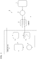
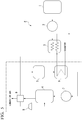
- a heat cycle facility A of the first embodiment includes a fuel tank 1, a pump 2, a vaporizer 3, a boiler 4, a turbine 5, a condenser 6 and a pump 7.
- the boiler 4, the turbine 5, the condenser 6 and the pump 7 are annularly interconnected through water pipes or steam pipes to form a Rankine cycle (heat cycle).
- the pump 2 among these components corresponds to the supplier of the present disclosure.
- the vaporizer 3 corresponds to the second vaporizer of the present disclosure.
- the boiler 4 corresponds to the first vaporizer of the present disclosure.
- the turbine 5 corresponds to the first motive power generator of the present disclosure.
- the condenser 6 corresponds to the condenser of the present disclosure.
- the pump 7 corresponds to the circulator of the present disclosure.
- the fuel tank 1 internally stores liquid ammonia as fuel.
- the pump 2 is connected to the fuel tank 1 through a predetermined fuel pipe, pumps out liquid ammonia from the fuel tank 1 and supplies it to the vaporizer 3.
- the vaporizer 3 is connected to the pump 2 through a predetermined fuel pipe and vaporizes the liquid ammonia using warm seawater supplied separately from the condenser 6 to produce gaseous ammonia. That is, the vaporizer 3 is a kind of heat-exchanger and produces gaseous ammonia by heat-exchanging the warm water that is the second liquid heating medium for liquid ammonia.
- the vaporizer 3 is connected to the boiler 4 through a predetermined fuel pipe and supplies gaseous ammonia as fuel to the boiler 4. In addition, the vaporizer 3 discharges the warm seawater after heat-exchange for the liquid ammonia to the outside.
- the boiler 4 is connected to the pump 7 through a water pipe and vaporizes water (the first liquid heating medium) supplied from the pump 7 by combusting as fuel the gaseous ammonia supplied from the vaporizer 3. That is, the boiler 4 combusts gaseous ammonia using combustion air taken in from the outside air as an oxidizing agent to produce combustion gas and vaporizes the water (the first liquid heating medium) by the heat energy of the combustion gas to produce water vapor (the first gas heating medium).
- the boiler 4 is connected to the turbine 5 through a steam pipe and outputs the water vapor to the turbine 5. That is, the boiler 4 vaporizes the first liquid heating medium by heat generated by combustion to obtain the first gas heating medium.
- the turbine 5 is a steam turbine and generates rotational motive power by using the water vapor (the first gas heating medium) supplied from the boiler 4 as a drive fluid.
- the turbine 5 is connected to the condenser 6 through a steam pipe and discharges the water vapor after power recovery to the condenser 6.
- the condenser 6 is configured to be supplied with seawater at a predetermined flow rate by a seawater pump (not shown) and condenses the water vapor (the first gas heating medium) received from the turbine 5 by using this seawater. That is, the condenser 6 cools the water vapor (the first gas heating medium) received from the turbine 5 by heat-exchange for separately received seawater (the second liquid heating medium) to return (condense) the water vapor to water (the first liquid heating medium).
- the condenser 6 is connected to the pump 7 through a water pipe and supplies the water (the first liquid heating medium) to the pump 7. In addition, the condenser 6 supplies seawater (warm seawater) warmed by heat-exchange for the water vapor (the first gas heating medium) to the vaporizer 3.
- the pump 7 pressurizes water (the first liquid heating medium) and supplies the pressurized water to the boiler 4. That is, in a circulation route configured of the boiler 4, the turbine 5, the condenser 6, the pump 7, the water pipes and the steam pipes, the pump 7 is a power source for circulating water (the first liquid heating medium) and water vapor (the first gas heating medium) in the direction of the arrow shown in FIG. 1 .
- the turbine 5 rotationally drives an electric generator by its own rotational motive power. That is, the heat cycle facility A of the first embodiment obtains electric power as a final acquisition by using the Rankine cycle (heat cycle).
- the first motive power generator of the present disclosure may be used for other than the driving source for the electric generator.
- liquid ammonia pumped out from the fuel tank 1 is phase-changed into gaseous ammonia, which is supplied to the boiler 4, by the operation of the pump 2 and the vaporizer 3.
- water is supplied to the boiler 4 by the operation of the pump 7.
- the boiler 4 vaporizes the water separately supplied from the pump 7 by combusting the gaseous ammonia supplied from the vaporizer 3 as fuel to produce water vapor.
- the turbine 5 generates rotational motive power by using the water vapor supplied from the boiler 4 as a drive fluid.
- the rotational motive power of the turbine 5 is used to drive the electric generator and is converted to electric power.
- the water vapor discharged from the turbine 5 is condensed by heat-exchange for seawater in the condensate 6 into water, which is supplied to the pump 7.
- rotational motive power is generated by water repeating the phase-transition between the liquid phase and the gas phase. Further, in the heat cycle facility A, the heat of seawater to be discharged to the outside is recovered as energy for vaporizing and heating liquid ammonia. Therefore, according to the heat cycle facility A, the heat efficiency of the system can be improved.
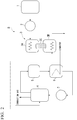
- FIG. 2 shows a heat cycle facility B of a modification of the first embodiment.
- the above vaporizer 3 (the second vaporizer) is configured of an ammonia heat transferer 3A, a seawater heat transferer 3B and a heat transfer plate 3C.
- the ammonia heat transferer 3A is a heat transfer passageway through which ammonia (liquid ammonia and gaseous ammonia) flows
- the seawater heat transferer 3B is a heat transfer passageway through which seawater flows.
- the heat transfer plate 3C is a member (plate member) for thermally connecting the ammonia heat transferer 3A and the seawater heat transferer 3B and connects the ammonia heat transferer 3A and the seawater heat transferer 3B so as to be heat transferable.
- the heat transfer plate 3C corresponds to the heat transfer body of the present disclosure.
- ammonia liquid ammonia and gaseous ammonia
- seawater the second liquid heating medium
- steel materials have sufficient corrosion resistance to ammonia, but have poor corrosion resistance to seawater. Therefore, although the flow passageway for ammonia may be made of steel, the flow passageway for seawater may be made of a material other than steel, such as titanium alloy.
- the ammonia heat transferer 3A and the seawater heat transferer 3B are formed of different materials in consideration of corrosion resistance.
- the ammonia heat transferer 3A and the heat transfer plate 3C are formed of carbon steel (steel material), and the seawater heat transferer 3B is formed of titanium alloy.
- the corrosion resistance of the second vaporizer can be improved compared to that of the heat cycle facility A of the first embodiment.
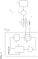
- a heat cycle facility C of the second embodiment has a configuration in which an expansion cycle of ammonia is combined with the Rankine cycle, and an expansion turbine 8 is added to the heat cycle facility A shown in FIG. 1 .
- an expansion cycle of ammonia is configured of the vaporizer 3 and the expansion turbine 8.
- the expansion turbine 8 corresponds to the second motive power generator of the present disclosure.
- the heat cycle facility C drives the expansion turbine 8 using the gaseous ammonia produced by the vaporizer 3.
- the gaseous ammonia after power recovery by the expansion turbine 8 is supplied as fuel to the boiler 4 to produce water vapor.
- rotational motive power is not generated only by the turbine 5 but is also generated by the expansion turbine 8. Therefore, according to the heat cycle facility C, in addition to the effects obtained by the heat cycle facilities A and B described above, it is possible to generate greater motive power than those of the heat cycle facilities A and B. For example, by driving an electric generator using the rotational motive power generated by the turbine 5, and by driving another electric generator using the rotational motive power generated by the expansion turbine 8, it is possible to generate greater electric power than the heat cycle facilities A and B.
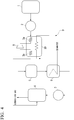
- FIG. 4 shows a heat cycle facility D of a first modification of the second embodiment.
- the heat cycle facility D includes a vaporizer 3D (the second vaporizer) provided with two heat transferers relating to ammonia (a first heat transferer 3a and a second heat transferer 3b), instead of the vaporizer 3.
- the seawater supplied from the condenser 6 is first heat-exchanged for the liquid ammonia passing through the first heat transferer 3a and then is heat-exchanged for the liquid ammonia passing through the second heat transferer 3b.
- the expansion turbine 8 is provided between the first heat transferer 3a and the second heat transferer 3b.
- the first heat transferer 3a produces gaseous ammonia by heat-exchanging liquid ammonia supplied from the pump 2 for seawater.
- the expansion turbine 8 is driven by the gaseous ammonia supplied from the first heat transferer 3a to generate rotational motive power.
- Gaseous ammonia is decreased in temperature and pressure by being deprived of heat energy by the expansion turbine 8 and is partially liquefied in some cases.
- the second heat transferer 3b is a re-heater that reheats and revaporizes ammonia (partially liquefied) supplied from the expansion turbine 8 by heat-exchanging the ammonia for seawater.
- the gaseous ammonia produced by the second heat transferer 3b is supplied to the boiler 4 as fuel.
- FIG. 5 shows a heat cycle facility E of a second modification of the second embodiment.
- a heat-exchanger 9 is added to the heat cycle facility C described above.
- the heat-exchanger 9 that heat-exchanges gaseous ammonia for the combustion gas (exhaust gas) of the boiler 4 is provided between the vaporizer 3 and the expansion turbine 8.
- the heat-exchanger 9 serves as an overheater that overheats the gaseous ammonia produced by the vaporizer 3 by heat-exchanging the gaseous ammonia for the combustion gas (exhaust gas) of the boiler 4.
- the heat cycle facility E having the above configuration, since the temperature of gaseous ammonia to be supplied to the boiler 4 can be increased compared to the heat cycle facility C described above, the flammability of the gaseous ammonia in the boiler 4 can be improved, and the temperature of the exhaust gas can be decreased, and thus the heat efficiency of the heat cycle facility E can be improved.
Landscapes
- Engineering & Computer Science (AREA)
- Chemical & Material Sciences (AREA)
- Combustion & Propulsion (AREA)
- Mechanical Engineering (AREA)
- General Engineering & Computer Science (AREA)
- Engine Equipment That Uses Special Cycles (AREA)
Applications Claiming Priority (2)
| Application Number | Priority Date | Filing Date | Title |
|---|---|---|---|
| JP2017016233A JP6819323B2 (ja) | 2017-01-31 | 2017-01-31 | 熱サイクル設備 |
| PCT/JP2018/002896 WO2018143171A1 (fr) | 2017-01-31 | 2018-01-30 | Installation à cycle thermodynamique |
Publications (3)
| Publication Number | Publication Date |
|---|---|
| EP3578767A1 true EP3578767A1 (fr) | 2019-12-11 |
| EP3578767A4 EP3578767A4 (fr) | 2020-11-11 |
| EP3578767B1 EP3578767B1 (fr) | 2021-08-25 |
Family
ID=63039581
Family Applications (1)
| Application Number | Title | Priority Date | Filing Date |
|---|---|---|---|
| EP18748151.0A Active EP3578767B1 (fr) | 2017-01-31 | 2018-01-30 | Installation à cycle thermodynamique |
Country Status (7)
| Country | Link |
|---|---|
| US (1) | US11162391B2 (fr) |
| EP (1) | EP3578767B1 (fr) |
| JP (1) | JP6819323B2 (fr) |
| KR (1) | KR20190097261A (fr) |
| CN (1) | CN110234846A (fr) |
| AU (1) | AU2018214902B2 (fr) |
| WO (1) | WO2018143171A1 (fr) |
Cited By (1)
| Publication number | Priority date | Publication date | Assignee | Title |
|---|---|---|---|---|
| EP4163488A1 (fr) * | 2021-10-08 | 2023-04-12 | Alfa Laval Corporate AB | Agencement pour la préparation d'un combustible gazeux à base d'ammoniac destiné à être brûlé dans une chaudière et procédé associé |
Families Citing this family (8)
| Publication number | Priority date | Publication date | Assignee | Title |
|---|---|---|---|---|
| JP7251225B2 (ja) * | 2019-03-11 | 2023-04-04 | 株式会社Ihi | 発電システム |
| CN112610881B (zh) * | 2020-11-29 | 2022-12-30 | 沪东重机有限公司 | 一种可调压汽化器及调压方法 |
| CN116802391A (zh) * | 2021-02-15 | 2023-09-22 | 三菱重工业株式会社 | 燃料供给方法、燃料供给设备、具备该燃料供给设备的燃料燃烧设备以及燃气轮机设备 |
| JP7811827B2 (ja) * | 2021-07-21 | 2026-02-06 | 三菱重工業株式会社 | アンモニア燃料供給ユニット、発電プラント、及びボイラの運転方法 |
| JP7793813B2 (ja) * | 2022-04-14 | 2026-01-05 | ヒュンダイ ヘビー インダストリーズ パワー システムズ カンパニー リミテッド | 燃料供給システム |
| KR20240158994A (ko) * | 2022-06-24 | 2024-11-05 | 가부시키가이샤 아이에이치아이 | 발전 시스템 |
| JP2024176859A (ja) * | 2023-06-09 | 2024-12-19 | 株式会社トクヤマ | 複合発電システム及び複合発電方法 |
| CN116951322A (zh) * | 2023-08-25 | 2023-10-27 | 氨邦科技有限公司 | 一种双介质超大容量液氨蒸发器 |
Family Cites Families (22)
| Publication number | Priority date | Publication date | Assignee | Title |
|---|---|---|---|---|
| FR2215835A6 (fr) * | 1973-01-26 | 1974-08-23 | Babcock Atlantique Sa | |
| JPS5191446A (fr) * | 1975-02-07 | 1976-08-11 | ||
| JPS6022167B2 (ja) * | 1976-09-22 | 1985-05-31 | 川崎重工業株式会社 | 二流体原動所 |
| US4503682A (en) * | 1982-07-21 | 1985-03-12 | Synthetic Sink | Low temperature engine system |
| JPH0491206A (ja) | 1990-08-06 | 1992-03-24 | Roa:Kk | 毛髪の延長方法とその接合器具 |
| JPH0491206U (fr) * | 1990-12-20 | 1992-08-10 | ||
| JPH11270352A (ja) | 1998-03-24 | 1999-10-05 | Mitsubishi Heavy Ind Ltd | 吸気冷却型ガスタービン発電設備及び同発電設備を用いた複合発電プラント |
| JP2003278598A (ja) * | 2002-03-20 | 2003-10-02 | Toyota Motor Corp | ランキンサイクルによる車輌の排熱回収方法及び装置 |
| JP2003307348A (ja) * | 2002-04-15 | 2003-10-31 | Matsushita Electric Ind Co Ltd | 熱交換装置 |
| CN1807848B (zh) * | 2005-01-20 | 2012-08-29 | 陈祖茂 | 双流体蒸汽式双发电装置 |
| JP4720673B2 (ja) * | 2006-08-16 | 2011-07-13 | 株式会社ニコン | 被写体追尾装置およびカメラ |
| CN101298843B (zh) * | 2008-06-05 | 2011-06-08 | 昆明理工大学 | 超临界朗肯循环回收低温余热动力的方法 |
| US8783035B2 (en) * | 2011-11-15 | 2014-07-22 | Shell Oil Company | System and process for generation of electrical power |
| GB201208771D0 (en) * | 2012-05-17 | 2012-07-04 | Atalla Naji A | Improved heat engine |
| JP5315492B1 (ja) | 2012-06-13 | 2013-10-16 | 武史 畑中 | 次世代カーボンフリー発電プラント及び次世代カーボンフリー発電方法並びに次世代カーボンフリー発電プラント及び次世代カーボンフリー発電方法に利用する尿素水 |
| JP2015190466A (ja) | 2014-03-31 | 2015-11-02 | 株式会社Ihi | 燃焼装置、ガスタービン及び発電装置 |
| US9038390B1 (en) * | 2014-10-10 | 2015-05-26 | Sten Kreuger | Apparatuses and methods for thermodynamic energy transfer, storage and retrieval |
| JP2016151191A (ja) | 2015-02-16 | 2016-08-22 | 国立研究開発法人産業技術総合研究所 | 発電システム |
| JP2016183839A (ja) * | 2015-03-26 | 2016-10-20 | 一般財団法人電力中央研究所 | 微粉炭焚きボイラ装置及び発電設備 |
| JP6212073B2 (ja) | 2015-06-29 | 2017-10-11 | ファナック株式会社 | プログラムの内容に応じて格納先を自動選択する機能を備えた数値制御装置 |
| CN106931481A (zh) * | 2017-03-03 | 2017-07-07 | 广东美的制冷设备有限公司 | 热循环系统和控制方法 |
| CN107789984B (zh) * | 2017-10-30 | 2019-09-20 | 清华大学 | 一种燃气轮机的脱硝系统和方法 |
-
2017
- 2017-01-31 JP JP2017016233A patent/JP6819323B2/ja active Active
-
2018
- 2018-01-30 CN CN201880008697.3A patent/CN110234846A/zh active Pending
- 2018-01-30 WO PCT/JP2018/002896 patent/WO2018143171A1/fr not_active Ceased
- 2018-01-30 KR KR1020197021950A patent/KR20190097261A/ko not_active Ceased
- 2018-01-30 AU AU2018214902A patent/AU2018214902B2/en active Active
- 2018-01-30 EP EP18748151.0A patent/EP3578767B1/fr active Active
-
2019
- 2019-07-29 US US16/524,525 patent/US11162391B2/en active Active
Cited By (2)
| Publication number | Priority date | Publication date | Assignee | Title |
|---|---|---|---|---|
| EP4163488A1 (fr) * | 2021-10-08 | 2023-04-12 | Alfa Laval Corporate AB | Agencement pour la préparation d'un combustible gazeux à base d'ammoniac destiné à être brûlé dans une chaudière et procédé associé |
| WO2023057196A1 (fr) * | 2021-10-08 | 2023-04-13 | Alfa Laval Corporate Ab | Agencement pour préparer un combustible à base d'ammoniac gazeux devant être brûlé dans une chaudière et procédé associé |
Also Published As
| Publication number | Publication date |
|---|---|
| EP3578767B1 (fr) | 2021-08-25 |
| AU2018214902A1 (en) | 2019-08-15 |
| WO2018143171A1 (fr) | 2018-08-09 |
| US11162391B2 (en) | 2021-11-02 |
| JP6819323B2 (ja) | 2021-01-27 |
| US20190345847A1 (en) | 2019-11-14 |
| CN110234846A (zh) | 2019-09-13 |
| JP2018123756A (ja) | 2018-08-09 |
| EP3578767A4 (fr) | 2020-11-11 |
| KR20190097261A (ko) | 2019-08-20 |
| AU2018214902B2 (en) | 2020-10-29 |
Similar Documents
| Publication | Publication Date | Title |
|---|---|---|
| US11162391B2 (en) | Heat cycle facility | |
| JP7173245B2 (ja) | 発電システム | |
| JP6734363B2 (ja) | ガスタービンプラント、及びその運転方法 | |
| EP2203630B1 (fr) | Système servant à récupérer de la chaleur résiduelle | |
| EP2345793B1 (fr) | Système à cycle de Rankine à double réchauffement et son procédé | |
| US8276383B2 (en) | Power generator using an organic rankine cycle drive with refrigerant mixtures and low waste heat exhaust as a heat source | |
| US8250847B2 (en) | Combined Brayton-Rankine cycle | |
| US9341086B2 (en) | Cascaded power plant using low and medium temperature source fluid | |
| US9784248B2 (en) | Cascaded power plant using low and medium temperature source fluid | |
| US20150075164A1 (en) | Cascaded power plant using low and medium temperature source fluid | |
| KR20050056941A (ko) | 캐스케이딩 폐루프 사이클 발전 | |
| JP2012082750A (ja) | 排熱回収発電装置およびこれを備えた船舶 | |
| EP0786590A1 (fr) | Centrale thermique à cycle combiné utilisant des déchets comme combustible | |
| KR20110079446A (ko) | Orc시스템 펌프 제어방법 | |
| KR101199525B1 (ko) | Orc시스템 | |
| KR102239301B1 (ko) | 발전시스템을 구비한 부유식 해상구조물 | |
| Klemencic et al. | Comparison of conventional and CO2 power generation cycles for waste heat recovery | |
| WO2024053577A1 (fr) | Système de moteur thermique | |
| JP4666641B2 (ja) | エネルギー供給システム、エネルギー供給方法、及びエネルギー供給システムの改造方法 | |
| CA2983533C (fr) | Generation d'energie a cycles combines | |
| WO2024252860A1 (fr) | Système et procédé de production d'énergie composite | |
| US20200392844A1 (en) | Conversion Chamber Power Device | |
| Khankari et al. | Comparative 4E-Analysis of A KCS11 with and without Solar Energy for Fluegas Waste Heat Recovery in a Coal-Fired Power Plant | |
| US10577986B2 (en) | Systems and methods for improving power plant efficiency | |
| Balanescu et al. | An innovative solution for clean terrestrial propulsion: Small scale combine cycle unit. Performance evaluation |
Legal Events
| Date | Code | Title | Description |
|---|---|---|---|
| STAA | Information on the status of an ep patent application or granted ep patent |
Free format text: STATUS: THE INTERNATIONAL PUBLICATION HAS BEEN MADE |
|
| PUAI | Public reference made under article 153(3) epc to a published international application that has entered the european phase |
Free format text: ORIGINAL CODE: 0009012 |
|
| STAA | Information on the status of an ep patent application or granted ep patent |
Free format text: STATUS: REQUEST FOR EXAMINATION WAS MADE |
|
| 17P | Request for examination filed |
Effective date: 20190729 |
|
| AK | Designated contracting states |
Kind code of ref document: A1 Designated state(s): AL AT BE BG CH CY CZ DE DK EE ES FI FR GB GR HR HU IE IS IT LI LT LU LV MC MK MT NL NO PL PT RO RS SE SI SK SM TR |
|
| A4 | Supplementary search report drawn up and despatched |
Effective date: 20201012 |
|
| RIC1 | Information provided on ipc code assigned before grant |
Ipc: F01K 23/06 20060101ALI20201007BHEP Ipc: F01K 25/10 20060101ALI20201007BHEP Ipc: F01K 23/04 20060101AFI20201007BHEP Ipc: F01K 9/00 20060101ALI20201007BHEP |
|
| GRAP | Despatch of communication of intention to grant a patent |
Free format text: ORIGINAL CODE: EPIDOSNIGR1 |
|
| STAA | Information on the status of an ep patent application or granted ep patent |
Free format text: STATUS: GRANT OF PATENT IS INTENDED |
|
| INTG | Intention to grant announced |
Effective date: 20210506 |
|
| GRAS | Grant fee paid |
Free format text: ORIGINAL CODE: EPIDOSNIGR3 |
|
| GRAA | (expected) grant |
Free format text: ORIGINAL CODE: 0009210 |
|
| STAA | Information on the status of an ep patent application or granted ep patent |
Free format text: STATUS: THE PATENT HAS BEEN GRANTED |
|
| AK | Designated contracting states |
Kind code of ref document: B1 Designated state(s): AL AT BE BG CH CY CZ DE DK EE ES FI FR GB GR HR HU IE IS IT LI LT LU LV MC MK MT NL NO PL PT RO RS SE SI SK SM TR |
|
| REG | Reference to a national code |
Ref country code: CH Ref legal event code: EP |
|
| REG | Reference to a national code |
Ref country code: IE Ref legal event code: FG4D Ref country code: AT Ref legal event code: REF Ref document number: 1424004 Country of ref document: AT Kind code of ref document: T Effective date: 20210915 |
|
| REG | Reference to a national code |
Ref country code: DE Ref legal event code: R096 Ref document number: 602018022451 Country of ref document: DE |
|
| REG | Reference to a national code |
Ref country code: LT Ref legal event code: MG9D |
|
| REG | Reference to a national code |
Ref country code: NL Ref legal event code: MP Effective date: 20210825 |
|
| REG | Reference to a national code |
Ref country code: AT Ref legal event code: MK05 Ref document number: 1424004 Country of ref document: AT Kind code of ref document: T Effective date: 20210825 |
|
| PG25 | Lapsed in a contracting state [announced via postgrant information from national office to epo] |
Ref country code: FI Free format text: LAPSE BECAUSE OF FAILURE TO SUBMIT A TRANSLATION OF THE DESCRIPTION OR TO PAY THE FEE WITHIN THE PRESCRIBED TIME-LIMIT Effective date: 20210825 Ref country code: ES Free format text: LAPSE BECAUSE OF FAILURE TO SUBMIT A TRANSLATION OF THE DESCRIPTION OR TO PAY THE FEE WITHIN THE PRESCRIBED TIME-LIMIT Effective date: 20210825 Ref country code: HR Free format text: LAPSE BECAUSE OF FAILURE TO SUBMIT A TRANSLATION OF THE DESCRIPTION OR TO PAY THE FEE WITHIN THE PRESCRIBED TIME-LIMIT Effective date: 20210825 Ref country code: SE Free format text: LAPSE BECAUSE OF FAILURE TO SUBMIT A TRANSLATION OF THE DESCRIPTION OR TO PAY THE FEE WITHIN THE PRESCRIBED TIME-LIMIT Effective date: 20210825 Ref country code: RS Free format text: LAPSE BECAUSE OF FAILURE TO SUBMIT A TRANSLATION OF THE DESCRIPTION OR TO PAY THE FEE WITHIN THE PRESCRIBED TIME-LIMIT Effective date: 20210825 Ref country code: NO Free format text: LAPSE BECAUSE OF FAILURE TO SUBMIT A TRANSLATION OF THE DESCRIPTION OR TO PAY THE FEE WITHIN THE PRESCRIBED TIME-LIMIT Effective date: 20211125 Ref country code: PT Free format text: LAPSE BECAUSE OF FAILURE TO SUBMIT A TRANSLATION OF THE DESCRIPTION OR TO PAY THE FEE WITHIN THE PRESCRIBED TIME-LIMIT Effective date: 20211227 Ref country code: AT Free format text: LAPSE BECAUSE OF FAILURE TO SUBMIT A TRANSLATION OF THE DESCRIPTION OR TO PAY THE FEE WITHIN THE PRESCRIBED TIME-LIMIT Effective date: 20210825 Ref country code: BG Free format text: LAPSE BECAUSE OF FAILURE TO SUBMIT A TRANSLATION OF THE DESCRIPTION OR TO PAY THE FEE WITHIN THE PRESCRIBED TIME-LIMIT Effective date: 20211125 Ref country code: LT Free format text: LAPSE BECAUSE OF FAILURE TO SUBMIT A TRANSLATION OF THE DESCRIPTION OR TO PAY THE FEE WITHIN THE PRESCRIBED TIME-LIMIT Effective date: 20210825 |
|
| PG25 | Lapsed in a contracting state [announced via postgrant information from national office to epo] |
Ref country code: PL Free format text: LAPSE BECAUSE OF FAILURE TO SUBMIT A TRANSLATION OF THE DESCRIPTION OR TO PAY THE FEE WITHIN THE PRESCRIBED TIME-LIMIT Effective date: 20210825 Ref country code: LV Free format text: LAPSE BECAUSE OF FAILURE TO SUBMIT A TRANSLATION OF THE DESCRIPTION OR TO PAY THE FEE WITHIN THE PRESCRIBED TIME-LIMIT Effective date: 20210825 Ref country code: GR Free format text: LAPSE BECAUSE OF FAILURE TO SUBMIT A TRANSLATION OF THE DESCRIPTION OR TO PAY THE FEE WITHIN THE PRESCRIBED TIME-LIMIT Effective date: 20211126 |
|
| PG25 | Lapsed in a contracting state [announced via postgrant information from national office to epo] |
Ref country code: NL Free format text: LAPSE BECAUSE OF FAILURE TO SUBMIT A TRANSLATION OF THE DESCRIPTION OR TO PAY THE FEE WITHIN THE PRESCRIBED TIME-LIMIT Effective date: 20210825 |
|
| PG25 | Lapsed in a contracting state [announced via postgrant information from national office to epo] |
Ref country code: DK Free format text: LAPSE BECAUSE OF FAILURE TO SUBMIT A TRANSLATION OF THE DESCRIPTION OR TO PAY THE FEE WITHIN THE PRESCRIBED TIME-LIMIT Effective date: 20210825 |
|
| REG | Reference to a national code |
Ref country code: DE Ref legal event code: R097 Ref document number: 602018022451 Country of ref document: DE |
|
| PG25 | Lapsed in a contracting state [announced via postgrant information from national office to epo] |
Ref country code: SM Free format text: LAPSE BECAUSE OF FAILURE TO SUBMIT A TRANSLATION OF THE DESCRIPTION OR TO PAY THE FEE WITHIN THE PRESCRIBED TIME-LIMIT Effective date: 20210825 Ref country code: SK Free format text: LAPSE BECAUSE OF FAILURE TO SUBMIT A TRANSLATION OF THE DESCRIPTION OR TO PAY THE FEE WITHIN THE PRESCRIBED TIME-LIMIT Effective date: 20210825 Ref country code: RO Free format text: LAPSE BECAUSE OF FAILURE TO SUBMIT A TRANSLATION OF THE DESCRIPTION OR TO PAY THE FEE WITHIN THE PRESCRIBED TIME-LIMIT Effective date: 20210825 Ref country code: EE Free format text: LAPSE BECAUSE OF FAILURE TO SUBMIT A TRANSLATION OF THE DESCRIPTION OR TO PAY THE FEE WITHIN THE PRESCRIBED TIME-LIMIT Effective date: 20210825 Ref country code: CZ Free format text: LAPSE BECAUSE OF FAILURE TO SUBMIT A TRANSLATION OF THE DESCRIPTION OR TO PAY THE FEE WITHIN THE PRESCRIBED TIME-LIMIT Effective date: 20210825 Ref country code: AL Free format text: LAPSE BECAUSE OF FAILURE TO SUBMIT A TRANSLATION OF THE DESCRIPTION OR TO PAY THE FEE WITHIN THE PRESCRIBED TIME-LIMIT Effective date: 20210825 |
|
| PLBE | No opposition filed within time limit |
Free format text: ORIGINAL CODE: 0009261 |
|
| STAA | Information on the status of an ep patent application or granted ep patent |
Free format text: STATUS: NO OPPOSITION FILED WITHIN TIME LIMIT |
|
| PG25 | Lapsed in a contracting state [announced via postgrant information from national office to epo] |
Ref country code: IT Free format text: LAPSE BECAUSE OF FAILURE TO SUBMIT A TRANSLATION OF THE DESCRIPTION OR TO PAY THE FEE WITHIN THE PRESCRIBED TIME-LIMIT Effective date: 20210825 |
|
| 26N | No opposition filed |
Effective date: 20220527 |
|
| PG25 | Lapsed in a contracting state [announced via postgrant information from national office to epo] |
Ref country code: SI Free format text: LAPSE BECAUSE OF FAILURE TO SUBMIT A TRANSLATION OF THE DESCRIPTION OR TO PAY THE FEE WITHIN THE PRESCRIBED TIME-LIMIT Effective date: 20210825 Ref country code: MC Free format text: LAPSE BECAUSE OF FAILURE TO SUBMIT A TRANSLATION OF THE DESCRIPTION OR TO PAY THE FEE WITHIN THE PRESCRIBED TIME-LIMIT Effective date: 20210825 |
|
| REG | Reference to a national code |
Ref country code: CH Ref legal event code: PL |
|
| GBPC | Gb: european patent ceased through non-payment of renewal fee |
Effective date: 20220130 |
|
| REG | Reference to a national code |
Ref country code: BE Ref legal event code: MM Effective date: 20220131 |
|
| PG25 | Lapsed in a contracting state [announced via postgrant information from national office to epo] |
Ref country code: LU Free format text: LAPSE BECAUSE OF NON-PAYMENT OF DUE FEES Effective date: 20220130 Ref country code: GB Free format text: LAPSE BECAUSE OF NON-PAYMENT OF DUE FEES Effective date: 20220130 |
|
| PG25 | Lapsed in a contracting state [announced via postgrant information from national office to epo] |
Ref country code: FR Free format text: LAPSE BECAUSE OF NON-PAYMENT OF DUE FEES Effective date: 20220131 Ref country code: BE Free format text: LAPSE BECAUSE OF NON-PAYMENT OF DUE FEES Effective date: 20220131 |
|
| PG25 | Lapsed in a contracting state [announced via postgrant information from national office to epo] |
Ref country code: LI Free format text: LAPSE BECAUSE OF NON-PAYMENT OF DUE FEES Effective date: 20220131 Ref country code: CH Free format text: LAPSE BECAUSE OF NON-PAYMENT OF DUE FEES Effective date: 20220131 |
|
| PG25 | Lapsed in a contracting state [announced via postgrant information from national office to epo] |
Ref country code: IE Free format text: LAPSE BECAUSE OF NON-PAYMENT OF DUE FEES Effective date: 20220130 |
|
| PG25 | Lapsed in a contracting state [announced via postgrant information from national office to epo] |
Ref country code: MK Free format text: LAPSE BECAUSE OF FAILURE TO SUBMIT A TRANSLATION OF THE DESCRIPTION OR TO PAY THE FEE WITHIN THE PRESCRIBED TIME-LIMIT Effective date: 20210825 Ref country code: CY Free format text: LAPSE BECAUSE OF FAILURE TO SUBMIT A TRANSLATION OF THE DESCRIPTION OR TO PAY THE FEE WITHIN THE PRESCRIBED TIME-LIMIT Effective date: 20210825 |
|
| PG25 | Lapsed in a contracting state [announced via postgrant information from national office to epo] |
Ref country code: HU Free format text: LAPSE BECAUSE OF FAILURE TO SUBMIT A TRANSLATION OF THE DESCRIPTION OR TO PAY THE FEE WITHIN THE PRESCRIBED TIME-LIMIT; INVALID AB INITIO Effective date: 20180130 |
|
| PG25 | Lapsed in a contracting state [announced via postgrant information from national office to epo] |
Ref country code: TR Free format text: LAPSE BECAUSE OF FAILURE TO SUBMIT A TRANSLATION OF THE DESCRIPTION OR TO PAY THE FEE WITHIN THE PRESCRIBED TIME-LIMIT Effective date: 20210825 |
|
| PG25 | Lapsed in a contracting state [announced via postgrant information from national office to epo] |
Ref country code: MT Free format text: LAPSE BECAUSE OF FAILURE TO SUBMIT A TRANSLATION OF THE DESCRIPTION OR TO PAY THE FEE WITHIN THE PRESCRIBED TIME-LIMIT Effective date: 20210825 |
|
| PGFP | Annual fee paid to national office [announced via postgrant information from national office to epo] |
Ref country code: DE Payment date: 20251217 Year of fee payment: 9 |