EP3578899B1 - Innenraumeinheit für klimaanlage - Google Patents
Innenraumeinheit für klimaanlage Download PDFInfo
- Publication number
- EP3578899B1 EP3578899B1 EP17890846.3A EP17890846A EP3578899B1 EP 3578899 B1 EP3578899 B1 EP 3578899B1 EP 17890846 A EP17890846 A EP 17890846A EP 3578899 B1 EP3578899 B1 EP 3578899B1
- Authority
- EP
- European Patent Office
- Prior art keywords
- air
- drain pan
- receiving portion
- indoor unit
- dew receiving
- Prior art date
- Legal status (The legal status is an assumption and is not a legal conclusion. Google has not performed a legal analysis and makes no representation as to the accuracy of the status listed.)
- Active
Links
Images



Classifications
-
- F—MECHANICAL ENGINEERING; LIGHTING; HEATING; WEAPONS; BLASTING
- F24—HEATING; RANGES; VENTILATING
- F24F—AIR-CONDITIONING; AIR-HUMIDIFICATION; VENTILATION; USE OF AIR CURRENTS FOR SCREENING
- F24F13/00—Details common to, or for air-conditioning, air-humidification, ventilation or use of air currents for screening
- F24F13/22—Means for preventing condensation or evacuating condensate
-
- F—MECHANICAL ENGINEERING; LIGHTING; HEATING; WEAPONS; BLASTING
- F24—HEATING; RANGES; VENTILATING
- F24F—AIR-CONDITIONING; AIR-HUMIDIFICATION; VENTILATION; USE OF AIR CURRENTS FOR SCREENING
- F24F1/00—Room units for air-conditioning, e.g. separate or self-contained units or units receiving primary air from a central station
- F24F1/0007—Indoor units, e.g. fan coil units
- F24F1/0083—Indoor units, e.g. fan coil units with dehumidification means
-
- F—MECHANICAL ENGINEERING; LIGHTING; HEATING; WEAPONS; BLASTING
- F24—HEATING; RANGES; VENTILATING
- F24F—AIR-CONDITIONING; AIR-HUMIDIFICATION; VENTILATION; USE OF AIR CURRENTS FOR SCREENING
- F24F1/00—Room units for air-conditioning, e.g. separate or self-contained units or units receiving primary air from a central station
- F24F1/0007—Indoor units, e.g. fan coil units
- F24F1/0043—Indoor units, e.g. fan coil units characterised by mounting arrangements
- F24F1/0057—Indoor units, e.g. fan coil units characterised by mounting arrangements mounted in or on a wall
-
- F—MECHANICAL ENGINEERING; LIGHTING; HEATING; WEAPONS; BLASTING
- F24—HEATING; RANGES; VENTILATING
- F24F—AIR-CONDITIONING; AIR-HUMIDIFICATION; VENTILATION; USE OF AIR CURRENTS FOR SCREENING
- F24F13/00—Details common to, or for air-conditioning, air-humidification, ventilation or use of air currents for screening
- F24F13/22—Means for preventing condensation or evacuating condensate
- F24F13/222—Means for preventing condensation or evacuating condensate for evacuating condensate
- F24F2013/227—Condensate pipe for drainage of condensate from the evaporator
Definitions
- the present invention relates to an indoor unit of an air-conditioning apparatus, more specifically, to a countermeasure against dew condensation on a drain pan.
- Patent Literature 1 discloses a countermeasure against dew condensation on a drain pan.
- the drain pan is made to have a hollow cross section in its central portion, and a groove is formed at a lowermost section in the central portion. This produces a heat insulating effect on the central portion of the drain pan, preventing dew condensation on the drain pan.
- Patent Literature 1 Japanese Unexamined Patent Application Publication No. 8-119111
- Patent Literature 1 while a countermeasure against dew condensation is applied to the central portion of the drain pan, it is not applied to a side portion of the drain pan. This gives rise to a problem in that dew condensation easily occurs at the side portion of the drain pan.
- the present invention has been made to solve the above problem, and aims to provide an indoor unit of an air-conditioning apparatus that is capable of preventing dew condensation on a side portion of the drain pan.
- An indoor unit of an air-conditioning apparatus includes: a heat exchanger configured to generate conditioned air by carrying out heat exchange between a refrigerant and indoor air; and a drain pan disposed below a lower end of the heat exchanger to collect dew condensation water.
- the drain pan includes at a side portion thereof: a side dew receiving portion configured to receive dew condensation water; and a recessed portion disposed below the side dew receiving portion, the recessed portion being recessed toward an other side portion opposite to the side portion.
- a side face of the drain pan is provided with a heat insulating sheet covering an entire opening of the recessed portion.
- the drain pan includes a recessed portion disposed below a side dew receiving portion, and a heat insulating sheet provided at a side face of the drain pan. This produces a high heat insulating effect on the side portion of the drain pan, preventing dew condensation on the side portion of the drain pan.
- FIG. 1 is an external perspective view of an indoor unit 100 of an air-conditioning apparatus according to the embodiment of the present invention as viewed from a front side.
- FIG. 2 is a schematic vertical cross-sectional view of the indoor unit 100 of the air-conditioning apparatus according to the embodiment of the present invention as viewed from a right side.
- the indoor unit 100 of the air-conditioning apparatus supplies conditioned air to an air-conditioned area, such as a room, by using a refrigeration cycle circulating refrigerant.
- an air-conditioned area such as a room
- a refrigeration cycle circulating refrigerant circulating refrigerant
- the indoor unit 100 includes a rear case 1 mounted on a wall, and a housing 2 attached to a front surface of the rear case 1.
- the housing 2 has an air inlet 3 for mainly taking indoor air into the housing 2, and an air outlet 4 for supplying conditioned air to the air-conditioned area.
- a front design panel 5 is openably attached to a front surface of the housing 2.
- the indoor unit 100 accommodates therein an air-sending fan 6 configured to take in indoor air from the air inlet 3 and blowing conditioned air through the air outlet 4, and a heat exchanger 7 which is disposed on an air path between the air inlet 3 and the air outlet 4 with its longitudinal direction extending along a left-right direction, and which is configured to generate conditioned air by carrying out heat exchange between a refrigerant and the indoor air.
- the indoor unit 100 further includes therein an electric component box (not shown) which accommodates a circuit board and other components, and a drain pan 10 disposed below a lower end of the heat exchanger 7 to collect dew condensation water from the heat exchanger 7.
- the drain pan 10 will be described later in detail.
- the air inlet 3 is formed in an upper portion of the housing 2 as an opening.
- the air outlet 4 is formed in a lower portion of the housing 2 as another opening.
- the air-sending fan 6 is disposed downstream of the air inlet 3 and upstream of the heat exchanger 7, and is an axial fan or a mixed flow fan, for example.
- the heat exchanger 7 is inverted V-shaped or A-shaped in vertical cross section, and is disposed on the leeward of the air-sending fan 6.
- the heat exchanger 7 may be a fin tube-type heat exchanger, for example.
- the air inlet 3 is provided with a finger guard and a filter (not shown). Further, the air outlet 4 is provided with a vertical wind direction adjusting plate 8 for controlling a blowing direction of air flow.
- the heat exchanger 7 is strictly inverted V-shaped or A-shaped in vertical cross section.
- the air-sending fan 6 is not limited to one disposed upstream of the heat exchanger 7. A cross-flow fan disposed downstream of the heat exchanger 7 may be applied as the air-sending fan 6.
- indoor air is sent by the air-sending fan 6 into the indoor unit 100 through the air inlet 3 formed in the upper portion of the housing 2.
- dust contained in the indoor air is removed by the filter (not shown).
- this indoor air is heated or cooled by the refrigerant inside the heat exchanger 7 to become conditioned air.
- the conditioned air is then blown out to the outside of the indoor unit 100, namely a to-be-air-conditioned area, through the air outlet 4 formed in the lower portion of the housing 2.
- FIG. 3 is a perspective view of the drain pan 10 of the indoor unit 100 of the air-conditioning apparatus according to the embodiment of the present invention as viewed from the front side.
- FIG. 4 is a plan view of a right side portion 10b of the drain pan 10 shown in FIG. 3 .
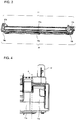
- FIG. 5 is a back view of the right side portion 10b of the drain pan 10 as shown in FIG. 3 .
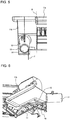
- FIG. 6 is a perspective view of the right side portion 10b of the drain pan 10 as shown in FIG. 3 as viewed from the front side.
- FIG. 7 is a side view of the right side portion 10b of the drain pan 10 as shown in FIG. 3 .
- Broken lines A and B respectively shown in FIGS. 4 and 5 each indicate a boundary between a central dew receiving portion 11a and a side dew receiving portion 11b. An arrow C in FIG. 5 will be described later.
- the drain pan 10 is disposed below the lower end of the heat exchanger 7, and collects dew condensation water adhering to the heat exchanger 7 during cooling operation of the indoor unit 100.
- the drain pan 10 has a configuration as shown in FIGS. 3 to 7 .
- the drain pan 10 includes a dew receiving unit 11 for receiving dew condensation water.
- the dew receiving unit 11 comprises: the central dew receiving portion 11a, which is located on a central portion 10a of the drain pan 10; and the side dew receiving portion 11b, which is located on each side portion 10b of the drain pan 10.
- a connecting portion 12 to which a drain hose (not shown) is to be connected is provided on a rear side of the side dew receiving portion 11b).
- the connecting portion 12 includes a cylindrical inner wall 13 and a drain port 14 defined by the surrounding inner wall 13.
- a flow path extending in the left-right direction and communicating with the side dew receiving portion 11 b is formed on an upper surface of the central dew receiving portion 11a. Additionally, a flow path extending in a front-back direction and communicating with the drain port 14 is formed on an upper surface of the side dew receiving portion 11b.
- the indoor unit 100 When installed, the indoor unit 100 is inclined with respect to a horizontal direction. Accordingly, the drain pan 10 is also inclined with respect to the horizontal direction. More specifically, upper surfaces of the central dew receiving portion 11a and the side dew receiving portion 11b are inclined in a direction in which the indoor unit 100 is inclined, and also toward the rear side.
- dew condensation water adhering to the heat exchanger 7 during cooling operation of the indoor unit 100 drops on the upper surface of the central dew receiving portion 11a, moves to the upper surface of the side dew receiving portion 11b inclined downward with respect to the horizontal direction, and is then drained to the outside of the indoor unit 100 from the drain port 14 of the connecting portion 12 through the drain hose.
- the drain pan 10 includes, at the side portion 10b thereof, a recessed portion 15 below the side dew receiving portion 11b.
- the recessed portion 15 is recessed toward the side portion 10b on the opposite side.
- the recessed portion 15 includes a surrounding wall 16.
- the surrounding wall 16 covers a lower face of the side dew receiving portion 11b, with space provided between them.
- the surrounding wall 16 includes plural ribs 17 protruding into the space.
- FIG. 8 illustrates a state where a heat insulating sheet 20 is adhered to the right side face of the drain pan 10 as shown in FIG. 4 .
- FIG. 9 is a schematic view for explaining an air layer 21 formed inside the right side portion 10b of the drain pan 10 as shown in FIG. 4 .
- a heat insulating sheet 20 which is a heat insulating material, is attached to the side face of the drain pan 10 in such a manner as to cover an entire opening of the recessed portion 15.
- a hollow air layer 21 is formed between the recessed portion 15 and the heat insulating sheet 20, as shown in FIG. 9 . Since thermal conductivity of air is extremely low, the air layer 21 functions as a heat insulating material having a high heat insulating effect. Thus, by virtue of the heat insulating sheet 20 and the air layer 21, a high heat insulating effect can be produced.
- dew condensation water After collected by the drain pan 10, dew condensation water always passes through the side dew receiving portion 11b when it is drained from the drain port 14. For this reason, dew condensation water tends to accumulate on the side dew receiving portion 11b. Further, dew condensation water flows on the side dew receiving portion 11b more slowly than on the central dew receiving portion 11a, as a result of which dew condensation easily occurs at the side dew receiving portion 11b. It is therefore necessary to take thorough measures dew condensation on the side dew receiving portion 11b. However, because of the heat insulating sheet 20 and the air layer 21, a high heat insulating effect can be produced at the side dew receiving portion 11b, and dew condensation can thus be prevented from occurring at the side dew receiving portion 11b.
- the heat insulating sheet 20 is made of polystyrene foam, which is commercially available as an inexpensive resin-based heat insulating material.
- the heat insulating sheet 20 originally has a sheet shape, and is cut according to a shape of the side face of the side dew receiving portion 11b.
- Polystyrene foam is soft and easy to cut with a tool such as scissors and a cutter.
- the heat insulating sheet 20 has an adhesion surface on at least one side thereof.
- the heat insulating sheet 20 is used as a heat insulating material for the side dew receiving portion 11b, it eliminates the need for die casting, which has previously been required, and also can be more easily attached to the side face of the drain pan 10. This can reduce manufacturing costs.
- the plural ribs 17 are provided at the surrounding wall 16 of the recessed portion 15, such that adhesion areas between the heat insulating sheet 20 and the side face of the drain pan 10 are increased when the heat insulating sheet 20 is attached to the side face of the drain pan 10. As a result, the heat insulating sheet 20 can be more easily attached to the side face of the drain pan 10.
- the recessed portion 15 is recessed at least up to a position at the inner wall 13 of the connecting portion 12 that is most proximal to the central dew receiving portion 11a (a position indicated by the arrow C in FIG. 5 ).
- the recessed portion 15 may be recessed at most up to the boundary between the central dew receiving portion 11a and the side dew receiving portion 11b. This is because the central dew receiving portion 11a does not require the air layer 21 for heat insulation since dew condensation water flows faster on the central dew receiving portion 11a than on the side dew receiving portion 11b and thus sufficient heat insulation for the central dew receiving portion 11a can be ensured by means such as affixing a heat insulating material (not shown) to a lower surface of the central dew receiving portion 11a.
- the indoor unit 100 of the air-conditioning apparatus includes: the heat exchanger 7configured to conditioned air by carrying out heat exchange between refrigerant and indoor air; and the drain pan 10 disposed below the lower end of the heat exchanger 7 to collect dew condensation water.
- the drain pan 10 includes, at the side portion 10b thereof, the side dew receiving portion 11b for receiving dew condensation water, and the recessed portion 15 disposed below the side dew receiving portion 11b and recessed toward the other side portion 10b on the opposite side of the side portion 10b.
- the heat insulating sheet 20 is provided at the side face of the drain pan 10 in such a manner as to cover the entire opening of the recessed portion 15.
- the indoor unit 100 of the air-conditioning apparatus includes the recessed portion 15 disposed below the side dew receiving portion 11b of the drain pan 10, and the heat insulating sheet 20 provided at the side face of the drain pan 10. This can produce a high heat insulating effect on the side dew receiving portion 11b, preventing dew condensation on the side dew receiving portion 11b.
- the indoor unit 100 of the air-conditioning apparatus includes, at the side dew receiving portion 11b, the connecting portion 12 having the inner wall 13 defining the drain port 14.
- the recessed portion 15 is recessed at least up to a position at the inner wall 13 that is most proximal to the central dew receiving portion 11a.
- the air layer 21 is formed in the entire lower part of the drain port 14, on which dew condensation most easily occurs. This can produce a high heat insulating effect on the side dew receiving portion 11b.
- the recessed portion 15 includes the surrounding wall 16 covering the lower face of the side dew receiving portion 11b, with space provided between them.
- the surrounding wall 16 includes the plural ribs 17 protruding into the space.
Landscapes
- Engineering & Computer Science (AREA)
- Chemical & Material Sciences (AREA)
- Combustion & Propulsion (AREA)
- Mechanical Engineering (AREA)
- General Engineering & Computer Science (AREA)
- Devices For Blowing Cold Air, Devices For Blowing Warm Air, And Means For Preventing Water Condensation In Air Conditioning Units (AREA)
Claims (3)
- Inneneinheit (100) einer Klimaanlage, umfassend:einen Wärmetauscher (7), der eingerichtet ist, Luft zu klimatisieren, durch Ausführen von Wärmetausch zwischen Kältemittel und Innenluft; undeine Ablaufwanne (10), die unter einem unteren Ende des Wärmetauschers (7) angeordnet ist, um Taukondensationswasser zu sammeln,wobei die Ablaufwanne (10) an einem Seitenabschnitt (10b) derselben aufweist:einen Tauaufnahme-Seitenabschnitt (11b), der eingerichtet ist, Taukondensationswasser aufzunehmen; unddadurch gekennzeichnet, dass:die Ablaufwanne (10) ferner an dem Seitenabschnitt (10b) derselben aufweisteinen vertieften Abschnitt (15), der unter dem Tauaufnahme-Seitenabschnitt (11b) angeordnet ist, wobei der vertiefte Abschnitt in Richtung eines anderen Seitenabschnitts (10b) gegenüber dem Seitenabschnitt (10b) vertieft ist, undwobei eine Seitenfläche der Ablaufwanne (10) mit einer Wärmeisolationsplatte (20) versehen ist, die eine gesamte Öffnung des vertieften Abschnitts (15) bedeckt.
- Inneneinheit (100) der Klimaanlage nach Anspruch 1, wobeidie Ablaufwanne (10) an einem Mittelabschnitt (10a) derselben einen Tauaufnahme-Mittelabschnitt (11a) aufweist, der eingerichtet ist, Taukondensationswasser aufzunehmen,der Taufaufnahme-Seitenabschnitt (11b) einen Verbindungsabschnitt (12) umfasst, der eine Innenwand (13) aufweist, wobei die Innenwand (13) einen Ablaufauslass (14) definiert, undder vertiefte Abschnitt (15) zumindest bis zu einer Position an der Innenwand (13) vertieft ist, wobei die Position möglichst nah an dem Tauaufnahme-Mittelabschnitt (11a) liegt.
- Inneneinheit (100) der Klimaanlage nach Anspruch 1 oder 2, wobeider vertiefte Abschnitt (15) eine umgebende Wand (16) aufweist, die eine untere Seite des Tauaufnahme-Seitenabschnitts (11b) bedeckt, wobei zwischen der umgebenden Wand und der unteren Seite ein Raum vorgesehen ist, unddie umgebende Wand (16) eine Vielzahl von Rippen (17) aufweist, die in den Raum vorstehen.
Applications Claiming Priority (1)
| Application Number | Priority Date | Filing Date | Title |
|---|---|---|---|
| PCT/JP2017/015346 WO2018189894A1 (ja) | 2017-04-14 | 2017-04-14 | 空気調和機の室内ユニット |
Publications (3)
| Publication Number | Publication Date |
|---|---|
| EP3578899A1 EP3578899A1 (de) | 2019-12-11 |
| EP3578899A4 EP3578899A4 (de) | 2020-03-25 |
| EP3578899B1 true EP3578899B1 (de) | 2021-09-22 |
Family
ID=63792523
Family Applications (1)
| Application Number | Title | Priority Date | Filing Date |
|---|---|---|---|
| EP17890846.3A Active EP3578899B1 (de) | 2017-04-14 | 2017-04-14 | Innenraumeinheit für klimaanlage |
Country Status (6)
| Country | Link |
|---|---|
| US (1) | US10982878B2 (de) |
| EP (1) | EP3578899B1 (de) |
| JP (1) | JP6833017B2 (de) |
| CN (1) | CN110494698A (de) |
| AU (1) | AU2017408933B2 (de) |
| WO (1) | WO2018189894A1 (de) |
Family Cites Families (24)
| Publication number | Priority date | Publication date | Assignee | Title |
|---|---|---|---|---|
| JPS5654717Y2 (de) * | 1976-01-16 | 1981-12-19 | ||
| JPS5650337Y2 (de) * | 1977-07-18 | 1981-11-25 | ||
| JPS5715275U (de) * | 1980-06-29 | 1982-01-26 | ||
| NL8105922A (nl) * | 1981-12-31 | 1983-07-18 | Philips Nv | Werkwijze voor het partieel metalliseren van elektrisch geleidende niet-metallische patronen. |
| JPS58119111U (ja) | 1982-02-08 | 1983-08-13 | 株式会社日立製作所 | 空気調和機の露受皿 |
| JPH0352902U (de) * | 1989-09-28 | 1991-05-22 | ||
| JPH058314U (ja) * | 1991-07-09 | 1993-02-05 | 松下冷機株式会社 | 空気調和機のドレンパン |
| JP3494241B2 (ja) | 1994-10-26 | 2004-02-09 | 小糸工業株式会社 | プラットホームの安全監視システムおよびこれを用いた安全監視方法 |
| JPH109604A (ja) | 1996-06-20 | 1998-01-16 | Hitachi Ltd | 露受け皿および空気調和機 |
| JPH11101464A (ja) * | 1997-09-30 | 1999-04-13 | Fujitsu General Ltd | 空気調和機 |
| JP2006125777A (ja) | 2004-10-29 | 2006-05-18 | Sharp Corp | 空気調和機のドレンパン及びこの製造方法 |
| CN101273236B (zh) * | 2005-10-31 | 2011-07-06 | 三菱电机株式会社 | 空调机的室内机 |
| JP4187034B2 (ja) * | 2006-10-05 | 2008-11-26 | ダイキン工業株式会社 | 空気調和装置の室内ユニット |
| JP2008292100A (ja) * | 2007-05-28 | 2008-12-04 | Hitachi Appliances Inc | 空気調和機 |
| JP5167088B2 (ja) | 2008-11-20 | 2013-03-21 | 三菱重工業株式会社 | 空気調和機 |
| JP2011020520A (ja) * | 2009-07-14 | 2011-02-03 | Keihin Corp | ドレンパン |
| JP5823881B2 (ja) * | 2012-01-17 | 2015-11-25 | シャープ株式会社 | 空気調和機 |
| JP5668739B2 (ja) * | 2012-09-28 | 2015-02-12 | ダイキン工業株式会社 | 空調室内機 |
| JP5950810B2 (ja) * | 2012-12-13 | 2016-07-13 | 三菱電機株式会社 | 空気調和機の室内機 |
| JP2014119131A (ja) * | 2012-12-13 | 2014-06-30 | Mitsubishi Electric Corp | 空気調和機の室内機 |
| JP2015169422A (ja) * | 2014-03-11 | 2015-09-28 | 三菱電機株式会社 | 空気調和機の室内機 |
| JP6252392B2 (ja) * | 2014-07-23 | 2017-12-27 | 三菱電機株式会社 | 空気調和機の室内機 |
| CN204826248U (zh) * | 2015-06-17 | 2015-12-02 | 江苏瀚渝易科节能新材料有限公司 | 一种带空气通道的保温板 |
| CN105910200B (zh) * | 2016-03-30 | 2018-12-21 | 天津大学 | 带有相变蓄热材料地暖模块的双末端空气源热泵系统 |
-
2017
- 2017-04-14 CN CN201780087842.7A patent/CN110494698A/zh active Pending
- 2017-04-14 US US16/483,446 patent/US10982878B2/en active Active
- 2017-04-14 WO PCT/JP2017/015346 patent/WO2018189894A1/ja not_active Ceased
- 2017-04-14 JP JP2019512157A patent/JP6833017B2/ja active Active
- 2017-04-14 EP EP17890846.3A patent/EP3578899B1/de active Active
- 2017-04-14 AU AU2017408933A patent/AU2017408933B2/en active Active
Also Published As
| Publication number | Publication date |
|---|---|
| JPWO2018189894A1 (ja) | 2019-11-21 |
| AU2017408933A1 (en) | 2019-09-19 |
| JP6833017B2 (ja) | 2021-02-24 |
| AU2017408933B2 (en) | 2020-07-09 |
| WO2018189894A1 (ja) | 2018-10-18 |
| CN110494698A (zh) | 2019-11-22 |
| EP3578899A4 (de) | 2020-03-25 |
| EP3578899A1 (de) | 2019-12-11 |
| US20200033024A1 (en) | 2020-01-30 |
| US10982878B2 (en) | 2021-04-20 |
Similar Documents
| Publication | Publication Date | Title |
|---|---|---|
| US6321556B1 (en) | Three-way mounting of an air conditioner | |
| EP2568226B1 (de) | Inneneinheit für eine Klimaanlagenvorrichtung sowie Klimaanlagenvorrichtung mit der Inneneinheit | |
| EP2933574B1 (de) | Innenraumeinheit einer klimaanlage | |
| WO2020155352A1 (zh) | 窗式空调器 | |
| CN104024759A (zh) | 空气调节机 | |
| CN110785057A (zh) | 一种具有立式风道的集成组机柜 | |
| EP3851758B1 (de) | Klimaanlage | |
| EP3557148B1 (de) | Klimaanlage | |
| CN206055765U (zh) | 空调机的室内机 | |
| EP3578899B1 (de) | Innenraumeinheit für klimaanlage | |
| KR101918589B1 (ko) | 차량용 통풍시트용 모터 모듈 | |
| CN111006318A (zh) | 空调室内机 | |
| CN109827241B (zh) | 壁挂式空调室内机的壳体组件、空调室内机和空调器 | |
| KR100605844B1 (ko) | 공기 조화 장치의 실내기 | |
| JP6422588B2 (ja) | 床置形空気調和機の室内機 | |
| CN218993532U (zh) | 室外机用侧板组件、室外机和空调系统 | |
| CN223283149U (zh) | 一种屋顶式空调 | |
| KR101240721B1 (ko) | 버스용 공조장치 | |
| CN112178763B (zh) | 空气调节装置 | |
| CN210267516U (zh) | 空调室内机 | |
| CN101762006A (zh) | 分体式空调室内机的前面板结合构造 | |
| KR100888873B1 (ko) | 공기조화기용 실외기의 열교환장치 | |
| EP2565544B1 (de) | Klimaanlage | |
| KR100553045B1 (ko) | 공기조화기 | |
| KR100564455B1 (ko) | 공기조화기 |
Legal Events
| Date | Code | Title | Description |
|---|---|---|---|
| STAA | Information on the status of an ep patent application or granted ep patent |
Free format text: STATUS: UNKNOWN |
|
| STAA | Information on the status of an ep patent application or granted ep patent |
Free format text: STATUS: THE INTERNATIONAL PUBLICATION HAS BEEN MADE |
|
| PUAI | Public reference made under article 153(3) epc to a published international application that has entered the european phase |
Free format text: ORIGINAL CODE: 0009012 |
|
| STAA | Information on the status of an ep patent application or granted ep patent |
Free format text: STATUS: REQUEST FOR EXAMINATION WAS MADE |
|
| 17P | Request for examination filed |
Effective date: 20180719 |
|
| AK | Designated contracting states |
Kind code of ref document: A1 Designated state(s): AL AT BE BG CH CY CZ DE DK EE ES FI FR GB GR HR HU IE IS IT LI LT LU LV MC MK MT NL NO PL PT RO RS SE SI SK SM TR |
|
| AX | Request for extension of the european patent |
Extension state: BA ME |
|
| A4 | Supplementary search report drawn up and despatched |
Effective date: 20200226 |
|
| RIC1 | Information provided on ipc code assigned before grant |
Ipc: F24F 13/22 20060101AFI20200220BHEP |
|
| DAV | Request for validation of the european patent (deleted) | ||
| DAX | Request for extension of the european patent (deleted) | ||
| GRAP | Despatch of communication of intention to grant a patent |
Free format text: ORIGINAL CODE: EPIDOSNIGR1 |
|
| STAA | Information on the status of an ep patent application or granted ep patent |
Free format text: STATUS: GRANT OF PATENT IS INTENDED |
|
| INTG | Intention to grant announced |
Effective date: 20201130 |
|
| GRAJ | Information related to disapproval of communication of intention to grant by the applicant or resumption of examination proceedings by the epo deleted |
Free format text: ORIGINAL CODE: EPIDOSDIGR1 |
|
| STAA | Information on the status of an ep patent application or granted ep patent |
Free format text: STATUS: REQUEST FOR EXAMINATION WAS MADE |
|
| GRAS | Grant fee paid |
Free format text: ORIGINAL CODE: EPIDOSNIGR3 |
|
| STAA | Information on the status of an ep patent application or granted ep patent |
Free format text: STATUS: GRANT OF PATENT IS INTENDED |
|
| GRAP | Despatch of communication of intention to grant a patent |
Free format text: ORIGINAL CODE: EPIDOSNIGR1 |
|
| INTC | Intention to grant announced (deleted) | ||
| INTG | Intention to grant announced |
Effective date: 20210428 |
|
| GRAA | (expected) grant |
Free format text: ORIGINAL CODE: 0009210 |
|
| STAA | Information on the status of an ep patent application or granted ep patent |
Free format text: STATUS: THE PATENT HAS BEEN GRANTED |
|
| AK | Designated contracting states |
Kind code of ref document: B1 Designated state(s): AL AT BE BG CH CY CZ DE DK EE ES FI FR GB GR HR HU IE IS IT LI LT LU LV MC MK MT NL NO PL PT RO RS SE SI SK SM TR |
|
| REG | Reference to a national code |
Ref country code: GB Ref legal event code: FG4D |
|
| REG | Reference to a national code |
Ref country code: DE Ref legal event code: R096 Ref document number: 602017046586 Country of ref document: DE |
|
| REG | Reference to a national code |
Ref country code: IE Ref legal event code: FG4D |
|
| REG | Reference to a national code |
Ref country code: CH Ref legal event code: EP Ref country code: AT Ref legal event code: REF Ref document number: 1432627 Country of ref document: AT Kind code of ref document: T Effective date: 20211015 |
|
| REG | Reference to a national code |
Ref country code: LT Ref legal event code: MG9D |
|
| REG | Reference to a national code |
Ref country code: NL Ref legal event code: MP Effective date: 20210922 |
|
| PG25 | Lapsed in a contracting state [announced via postgrant information from national office to epo] |
Ref country code: HR Free format text: LAPSE BECAUSE OF FAILURE TO SUBMIT A TRANSLATION OF THE DESCRIPTION OR TO PAY THE FEE WITHIN THE PRESCRIBED TIME-LIMIT Effective date: 20210922 Ref country code: FI Free format text: LAPSE BECAUSE OF FAILURE TO SUBMIT A TRANSLATION OF THE DESCRIPTION OR TO PAY THE FEE WITHIN THE PRESCRIBED TIME-LIMIT Effective date: 20210922 Ref country code: RS Free format text: LAPSE BECAUSE OF FAILURE TO SUBMIT A TRANSLATION OF THE DESCRIPTION OR TO PAY THE FEE WITHIN THE PRESCRIBED TIME-LIMIT Effective date: 20210922 Ref country code: SE Free format text: LAPSE BECAUSE OF FAILURE TO SUBMIT A TRANSLATION OF THE DESCRIPTION OR TO PAY THE FEE WITHIN THE PRESCRIBED TIME-LIMIT Effective date: 20210922 Ref country code: LT Free format text: LAPSE BECAUSE OF FAILURE TO SUBMIT A TRANSLATION OF THE DESCRIPTION OR TO PAY THE FEE WITHIN THE PRESCRIBED TIME-LIMIT Effective date: 20210922 Ref country code: BG Free format text: LAPSE BECAUSE OF FAILURE TO SUBMIT A TRANSLATION OF THE DESCRIPTION OR TO PAY THE FEE WITHIN THE PRESCRIBED TIME-LIMIT Effective date: 20211222 Ref country code: NO Free format text: LAPSE BECAUSE OF FAILURE TO SUBMIT A TRANSLATION OF THE DESCRIPTION OR TO PAY THE FEE WITHIN THE PRESCRIBED TIME-LIMIT Effective date: 20211222 |
|
| REG | Reference to a national code |
Ref country code: AT Ref legal event code: MK05 Ref document number: 1432627 Country of ref document: AT Kind code of ref document: T Effective date: 20210922 |
|
| PG25 | Lapsed in a contracting state [announced via postgrant information from national office to epo] |
Ref country code: LV Free format text: LAPSE BECAUSE OF FAILURE TO SUBMIT A TRANSLATION OF THE DESCRIPTION OR TO PAY THE FEE WITHIN THE PRESCRIBED TIME-LIMIT Effective date: 20210922 Ref country code: GR Free format text: LAPSE BECAUSE OF FAILURE TO SUBMIT A TRANSLATION OF THE DESCRIPTION OR TO PAY THE FEE WITHIN THE PRESCRIBED TIME-LIMIT Effective date: 20211223 |
|
| PG25 | Lapsed in a contracting state [announced via postgrant information from national office to epo] |
Ref country code: AT Free format text: LAPSE BECAUSE OF FAILURE TO SUBMIT A TRANSLATION OF THE DESCRIPTION OR TO PAY THE FEE WITHIN THE PRESCRIBED TIME-LIMIT Effective date: 20210922 |
|
| PG25 | Lapsed in a contracting state [announced via postgrant information from national office to epo] |
Ref country code: IS Free format text: LAPSE BECAUSE OF FAILURE TO SUBMIT A TRANSLATION OF THE DESCRIPTION OR TO PAY THE FEE WITHIN THE PRESCRIBED TIME-LIMIT Effective date: 20220122 Ref country code: SK Free format text: LAPSE BECAUSE OF FAILURE TO SUBMIT A TRANSLATION OF THE DESCRIPTION OR TO PAY THE FEE WITHIN THE PRESCRIBED TIME-LIMIT Effective date: 20210922 Ref country code: RO Free format text: LAPSE BECAUSE OF FAILURE TO SUBMIT A TRANSLATION OF THE DESCRIPTION OR TO PAY THE FEE WITHIN THE PRESCRIBED TIME-LIMIT Effective date: 20210922 Ref country code: PT Free format text: LAPSE BECAUSE OF FAILURE TO SUBMIT A TRANSLATION OF THE DESCRIPTION OR TO PAY THE FEE WITHIN THE PRESCRIBED TIME-LIMIT Effective date: 20220124 Ref country code: PL Free format text: LAPSE BECAUSE OF FAILURE TO SUBMIT A TRANSLATION OF THE DESCRIPTION OR TO PAY THE FEE WITHIN THE PRESCRIBED TIME-LIMIT Effective date: 20210922 Ref country code: NL Free format text: LAPSE BECAUSE OF FAILURE TO SUBMIT A TRANSLATION OF THE DESCRIPTION OR TO PAY THE FEE WITHIN THE PRESCRIBED TIME-LIMIT Effective date: 20210922 Ref country code: ES Free format text: LAPSE BECAUSE OF FAILURE TO SUBMIT A TRANSLATION OF THE DESCRIPTION OR TO PAY THE FEE WITHIN THE PRESCRIBED TIME-LIMIT Effective date: 20210922 Ref country code: EE Free format text: LAPSE BECAUSE OF FAILURE TO SUBMIT A TRANSLATION OF THE DESCRIPTION OR TO PAY THE FEE WITHIN THE PRESCRIBED TIME-LIMIT Effective date: 20210922 Ref country code: CZ Free format text: LAPSE BECAUSE OF FAILURE TO SUBMIT A TRANSLATION OF THE DESCRIPTION OR TO PAY THE FEE WITHIN THE PRESCRIBED TIME-LIMIT Effective date: 20210922 Ref country code: AL Free format text: LAPSE BECAUSE OF FAILURE TO SUBMIT A TRANSLATION OF THE DESCRIPTION OR TO PAY THE FEE WITHIN THE PRESCRIBED TIME-LIMIT Effective date: 20210922 |
|
| REG | Reference to a national code |
Ref country code: DE Ref legal event code: R097 Ref document number: 602017046586 Country of ref document: DE |
|
| PG25 | Lapsed in a contracting state [announced via postgrant information from national office to epo] |
Ref country code: DK Free format text: LAPSE BECAUSE OF FAILURE TO SUBMIT A TRANSLATION OF THE DESCRIPTION OR TO PAY THE FEE WITHIN THE PRESCRIBED TIME-LIMIT Effective date: 20210922 |
|
| PLBE | No opposition filed within time limit |
Free format text: ORIGINAL CODE: 0009261 |
|
| STAA | Information on the status of an ep patent application or granted ep patent |
Free format text: STATUS: NO OPPOSITION FILED WITHIN TIME LIMIT |
|
| 26N | No opposition filed |
Effective date: 20220623 |
|
| PG25 | Lapsed in a contracting state [announced via postgrant information from national office to epo] |
Ref country code: SI Free format text: LAPSE BECAUSE OF FAILURE TO SUBMIT A TRANSLATION OF THE DESCRIPTION OR TO PAY THE FEE WITHIN THE PRESCRIBED TIME-LIMIT Effective date: 20210922 |
|
| REG | Reference to a national code |
Ref country code: CH Ref legal event code: PL |
|
| GBPC | Gb: european patent ceased through non-payment of renewal fee |
Effective date: 20220414 |
|
| REG | Reference to a national code |
Ref country code: BE Ref legal event code: MM Effective date: 20220430 |
|
| PG25 | Lapsed in a contracting state [announced via postgrant information from national office to epo] |
Ref country code: MC Free format text: LAPSE BECAUSE OF FAILURE TO SUBMIT A TRANSLATION OF THE DESCRIPTION OR TO PAY THE FEE WITHIN THE PRESCRIBED TIME-LIMIT Effective date: 20210922 Ref country code: LU Free format text: LAPSE BECAUSE OF NON-PAYMENT OF DUE FEES Effective date: 20220414 Ref country code: LI Free format text: LAPSE BECAUSE OF NON-PAYMENT OF DUE FEES Effective date: 20220430 Ref country code: IT Free format text: LAPSE BECAUSE OF FAILURE TO SUBMIT A TRANSLATION OF THE DESCRIPTION OR TO PAY THE FEE WITHIN THE PRESCRIBED TIME-LIMIT Effective date: 20210922 Ref country code: GB Free format text: LAPSE BECAUSE OF NON-PAYMENT OF DUE FEES Effective date: 20220414 Ref country code: FR Free format text: LAPSE BECAUSE OF NON-PAYMENT OF DUE FEES Effective date: 20220430 Ref country code: CH Free format text: LAPSE BECAUSE OF NON-PAYMENT OF DUE FEES Effective date: 20220430 |
|
| PG25 | Lapsed in a contracting state [announced via postgrant information from national office to epo] |
Ref country code: BE Free format text: LAPSE BECAUSE OF NON-PAYMENT OF DUE FEES Effective date: 20220430 |
|
| PG25 | Lapsed in a contracting state [announced via postgrant information from national office to epo] |
Ref country code: IE Free format text: LAPSE BECAUSE OF NON-PAYMENT OF DUE FEES Effective date: 20220414 |
|
| P01 | Opt-out of the competence of the unified patent court (upc) registered |
Effective date: 20230512 |
|
| PG25 | Lapsed in a contracting state [announced via postgrant information from national office to epo] |
Ref country code: SM Free format text: LAPSE BECAUSE OF FAILURE TO SUBMIT A TRANSLATION OF THE DESCRIPTION OR TO PAY THE FEE WITHIN THE PRESCRIBED TIME-LIMIT Effective date: 20210922 Ref country code: MK Free format text: LAPSE BECAUSE OF FAILURE TO SUBMIT A TRANSLATION OF THE DESCRIPTION OR TO PAY THE FEE WITHIN THE PRESCRIBED TIME-LIMIT Effective date: 20210922 Ref country code: CY Free format text: LAPSE BECAUSE OF FAILURE TO SUBMIT A TRANSLATION OF THE DESCRIPTION OR TO PAY THE FEE WITHIN THE PRESCRIBED TIME-LIMIT Effective date: 20210922 |
|
| PG25 | Lapsed in a contracting state [announced via postgrant information from national office to epo] |
Ref country code: HU Free format text: LAPSE BECAUSE OF FAILURE TO SUBMIT A TRANSLATION OF THE DESCRIPTION OR TO PAY THE FEE WITHIN THE PRESCRIBED TIME-LIMIT; INVALID AB INITIO Effective date: 20170414 |
|
| PG25 | Lapsed in a contracting state [announced via postgrant information from national office to epo] |
Ref country code: MT Free format text: LAPSE BECAUSE OF FAILURE TO SUBMIT A TRANSLATION OF THE DESCRIPTION OR TO PAY THE FEE WITHIN THE PRESCRIBED TIME-LIMIT Effective date: 20210922 |
|
| PGFP | Annual fee paid to national office [announced via postgrant information from national office to epo] |
Ref country code: DE Payment date: 20250305 Year of fee payment: 9 |
|
| PG25 | Lapsed in a contracting state [announced via postgrant information from national office to epo] |
Ref country code: TR Free format text: LAPSE BECAUSE OF FAILURE TO SUBMIT A TRANSLATION OF THE DESCRIPTION OR TO PAY THE FEE WITHIN THE PRESCRIBED TIME-LIMIT Effective date: 20210922 |