EP3580042B1 - Druckkopfanordnung mit lichtemittierenden vorrichtungen und photonendetektoren - Google Patents
Druckkopfanordnung mit lichtemittierenden vorrichtungen und photonendetektoren Download PDFInfo
- Publication number
- EP3580042B1 EP3580042B1 EP17906370.6A EP17906370A EP3580042B1 EP 3580042 B1 EP3580042 B1 EP 3580042B1 EP 17906370 A EP17906370 A EP 17906370A EP 3580042 B1 EP3580042 B1 EP 3580042B1
- Authority
- EP
- European Patent Office
- Prior art keywords
- droplet
- nozzle
- controller
- build material
- material particles
- Prior art date
- Legal status (The legal status is an assumption and is not a legal conclusion. Google has not performed a legal analysis and makes no representation as to the accuracy of the status listed.)
- Active
Links
Images



Classifications
-
- B—PERFORMING OPERATIONS; TRANSPORTING
- B29—WORKING OF PLASTICS; WORKING OF SUBSTANCES IN A PLASTIC STATE IN GENERAL
- B29C—SHAPING OR JOINING OF PLASTICS; SHAPING OF MATERIAL IN A PLASTIC STATE, NOT OTHERWISE PROVIDED FOR; AFTER-TREATMENT OF THE SHAPED PRODUCTS, e.g. REPAIRING
- B29C64/00—Additive manufacturing, i.e. manufacturing of three-dimensional [3D] objects by additive deposition, additive agglomeration or additive layering, e.g. by 3D printing, stereolithography or selective laser sintering
- B29C64/10—Processes of additive manufacturing
- B29C64/165—Processes of additive manufacturing using a combination of solid and fluid materials, e.g. a powder selectively bound by a liquid binder, catalyst, inhibitor or energy absorber
-
- B—PERFORMING OPERATIONS; TRANSPORTING
- B22—CASTING; POWDER METALLURGY
- B22F—WORKING METALLIC POWDER; MANUFACTURE OF ARTICLES FROM METALLIC POWDER; MAKING METALLIC POWDER; APPARATUS OR DEVICES SPECIALLY ADAPTED FOR METALLIC POWDER
- B22F10/00—Additive manufacturing of workpieces or articles from metallic powder
- B22F10/20—Direct sintering or melting
- B22F10/22—Direct deposition of molten metal
-
- B—PERFORMING OPERATIONS; TRANSPORTING
- B22—CASTING; POWDER METALLURGY
- B22F—WORKING METALLIC POWDER; MANUFACTURE OF ARTICLES FROM METALLIC POWDER; MAKING METALLIC POWDER; APPARATUS OR DEVICES SPECIALLY ADAPTED FOR METALLIC POWDER
- B22F10/00—Additive manufacturing of workpieces or articles from metallic powder
- B22F10/80—Data acquisition or data processing
- B22F10/85—Data acquisition or data processing for controlling or regulating additive manufacturing processes
-
- B—PERFORMING OPERATIONS; TRANSPORTING
- B22—CASTING; POWDER METALLURGY
- B22F—WORKING METALLIC POWDER; MANUFACTURE OF ARTICLES FROM METALLIC POWDER; MAKING METALLIC POWDER; APPARATUS OR DEVICES SPECIALLY ADAPTED FOR METALLIC POWDER
- B22F12/00—Apparatus or devices specially adapted for additive manufacturing; Auxiliary means for additive manufacturing; Combinations of additive manufacturing apparatus or devices with other processing apparatus or devices
- B22F12/50—Means for feeding of material, e.g. heads
- B22F12/53—Nozzles
-
- B—PERFORMING OPERATIONS; TRANSPORTING
- B22—CASTING; POWDER METALLURGY
- B22F—WORKING METALLIC POWDER; MANUFACTURE OF ARTICLES FROM METALLIC POWDER; MAKING METALLIC POWDER; APPARATUS OR DEVICES SPECIALLY ADAPTED FOR METALLIC POWDER
- B22F12/00—Apparatus or devices specially adapted for additive manufacturing; Auxiliary means for additive manufacturing; Combinations of additive manufacturing apparatus or devices with other processing apparatus or devices
- B22F12/90—Means for process control, e.g. cameras or sensors
-
- B—PERFORMING OPERATIONS; TRANSPORTING
- B29—WORKING OF PLASTICS; WORKING OF SUBSTANCES IN A PLASTIC STATE IN GENERAL
- B29C—SHAPING OR JOINING OF PLASTICS; SHAPING OF MATERIAL IN A PLASTIC STATE, NOT OTHERWISE PROVIDED FOR; AFTER-TREATMENT OF THE SHAPED PRODUCTS, e.g. REPAIRING
- B29C64/00—Additive manufacturing, i.e. manufacturing of three-dimensional [3D] objects by additive deposition, additive agglomeration or additive layering, e.g. by 3D printing, stereolithography or selective laser sintering
- B29C64/10—Processes of additive manufacturing
- B29C64/106—Processes of additive manufacturing using only liquids or viscous materials, e.g. depositing a continuous bead of viscous material
- B29C64/112—Processes of additive manufacturing using only liquids or viscous materials, e.g. depositing a continuous bead of viscous material using individual droplets, e.g. from jetting heads
-
- B—PERFORMING OPERATIONS; TRANSPORTING
- B29—WORKING OF PLASTICS; WORKING OF SUBSTANCES IN A PLASTIC STATE IN GENERAL
- B29C—SHAPING OR JOINING OF PLASTICS; SHAPING OF MATERIAL IN A PLASTIC STATE, NOT OTHERWISE PROVIDED FOR; AFTER-TREATMENT OF THE SHAPED PRODUCTS, e.g. REPAIRING
- B29C64/00—Additive manufacturing, i.e. manufacturing of three-dimensional [3D] objects by additive deposition, additive agglomeration or additive layering, e.g. by 3D printing, stereolithography or selective laser sintering
- B29C64/20—Apparatus for additive manufacturing; Details thereof or accessories therefor
- B29C64/205—Means for applying layers
- B29C64/209—Heads; Nozzles
-
- B—PERFORMING OPERATIONS; TRANSPORTING
- B29—WORKING OF PLASTICS; WORKING OF SUBSTANCES IN A PLASTIC STATE IN GENERAL
- B29C—SHAPING OR JOINING OF PLASTICS; SHAPING OF MATERIAL IN A PLASTIC STATE, NOT OTHERWISE PROVIDED FOR; AFTER-TREATMENT OF THE SHAPED PRODUCTS, e.g. REPAIRING
- B29C64/00—Additive manufacturing, i.e. manufacturing of three-dimensional [3D] objects by additive deposition, additive agglomeration or additive layering, e.g. by 3D printing, stereolithography or selective laser sintering
- B29C64/20—Apparatus for additive manufacturing; Details thereof or accessories therefor
- B29C64/264—Arrangements for irradiation
- B29C64/268—Arrangements for irradiation using laser beams; using electron beams [EB]
-
- B—PERFORMING OPERATIONS; TRANSPORTING
- B29—WORKING OF PLASTICS; WORKING OF SUBSTANCES IN A PLASTIC STATE IN GENERAL
- B29C—SHAPING OR JOINING OF PLASTICS; SHAPING OF MATERIAL IN A PLASTIC STATE, NOT OTHERWISE PROVIDED FOR; AFTER-TREATMENT OF THE SHAPED PRODUCTS, e.g. REPAIRING
- B29C64/00—Additive manufacturing, i.e. manufacturing of three-dimensional [3D] objects by additive deposition, additive agglomeration or additive layering, e.g. by 3D printing, stereolithography or selective laser sintering
- B29C64/20—Apparatus for additive manufacturing; Details thereof or accessories therefor
- B29C64/264—Arrangements for irradiation
- B29C64/277—Arrangements for irradiation using multiple radiation means, e.g. micromirrors or multiple light-emitting diodes [LED]
- B29C64/282—Arrangements for irradiation using multiple radiation means, e.g. micromirrors or multiple light-emitting diodes [LED] of the same type, e.g. using different energy levels
-
- B—PERFORMING OPERATIONS; TRANSPORTING
- B29—WORKING OF PLASTICS; WORKING OF SUBSTANCES IN A PLASTIC STATE IN GENERAL
- B29C—SHAPING OR JOINING OF PLASTICS; SHAPING OF MATERIAL IN A PLASTIC STATE, NOT OTHERWISE PROVIDED FOR; AFTER-TREATMENT OF THE SHAPED PRODUCTS, e.g. REPAIRING
- B29C64/00—Additive manufacturing, i.e. manufacturing of three-dimensional [3D] objects by additive deposition, additive agglomeration or additive layering, e.g. by 3D printing, stereolithography or selective laser sintering
- B29C64/30—Auxiliary operations or equipment
- B29C64/386—Data acquisition or data processing for additive manufacturing
- B29C64/393—Data acquisition or data processing for additive manufacturing for controlling or regulating additive manufacturing processes
-
- B—PERFORMING OPERATIONS; TRANSPORTING
- B33—ADDITIVE MANUFACTURING TECHNOLOGY
- B33Y—ADDITIVE MANUFACTURING, i.e. MANUFACTURING OF THREE-DIMENSIONAL [3D] OBJECTS BY ADDITIVE DEPOSITION, ADDITIVE AGGLOMERATION OR ADDITIVE LAYERING, e.g. BY 3D PRINTING, STEREOLITHOGRAPHY OR SELECTIVE LASER SINTERING
- B33Y30/00—Apparatus for additive manufacturing; Details thereof or accessories therefor
-
- B—PERFORMING OPERATIONS; TRANSPORTING
- B22—CASTING; POWDER METALLURGY
- B22F—WORKING METALLIC POWDER; MANUFACTURE OF ARTICLES FROM METALLIC POWDER; MAKING METALLIC POWDER; APPARATUS OR DEVICES SPECIALLY ADAPTED FOR METALLIC POWDER
- B22F12/00—Apparatus or devices specially adapted for additive manufacturing; Auxiliary means for additive manufacturing; Combinations of additive manufacturing apparatus or devices with other processing apparatus or devices
- B22F12/40—Radiation means
- B22F12/44—Radiation means characterised by the configuration of the radiation means
- B22F12/45—Two or more
-
- B—PERFORMING OPERATIONS; TRANSPORTING
- B22—CASTING; POWDER METALLURGY
- B22F—WORKING METALLIC POWDER; MANUFACTURE OF ARTICLES FROM METALLIC POWDER; MAKING METALLIC POWDER; APPARATUS OR DEVICES SPECIALLY ADAPTED FOR METALLIC POWDER
- B22F12/00—Apparatus or devices specially adapted for additive manufacturing; Auxiliary means for additive manufacturing; Combinations of additive manufacturing apparatus or devices with other processing apparatus or devices
- B22F12/50—Means for feeding of material, e.g. heads
- B22F12/55—Two or more means for feeding material
-
- B—PERFORMING OPERATIONS; TRANSPORTING
- B22—CASTING; POWDER METALLURGY
- B22F—WORKING METALLIC POWDER; MANUFACTURE OF ARTICLES FROM METALLIC POWDER; MAKING METALLIC POWDER; APPARATUS OR DEVICES SPECIALLY ADAPTED FOR METALLIC POWDER
- B22F2999/00—Aspects linked to processes or compositions used in powder metallurgy
-
- B—PERFORMING OPERATIONS; TRANSPORTING
- B33—ADDITIVE MANUFACTURING TECHNOLOGY
- B33Y—ADDITIVE MANUFACTURING, i.e. MANUFACTURING OF THREE-DIMENSIONAL [3D] OBJECTS BY ADDITIVE DEPOSITION, ADDITIVE AGGLOMERATION OR ADDITIVE LAYERING, e.g. BY 3D PRINTING, STEREOLITHOGRAPHY OR SELECTIVE LASER SINTERING
- B33Y10/00—Processes of additive manufacturing
-
- B—PERFORMING OPERATIONS; TRANSPORTING
- B33—ADDITIVE MANUFACTURING TECHNOLOGY
- B33Y—ADDITIVE MANUFACTURING, i.e. MANUFACTURING OF THREE-DIMENSIONAL [3D] OBJECTS BY ADDITIVE DEPOSITION, ADDITIVE AGGLOMERATION OR ADDITIVE LAYERING, e.g. BY 3D PRINTING, STEREOLITHOGRAPHY OR SELECTIVE LASER SINTERING
- B33Y50/00—Data acquisition or data processing for additive manufacturing
- B33Y50/02—Data acquisition or data processing for additive manufacturing for controlling or regulating additive manufacturing processes
-
- Y—GENERAL TAGGING OF NEW TECHNOLOGICAL DEVELOPMENTS; GENERAL TAGGING OF CROSS-SECTIONAL TECHNOLOGIES SPANNING OVER SEVERAL SECTIONS OF THE IPC; TECHNICAL SUBJECTS COVERED BY FORMER USPC CROSS-REFERENCE ART COLLECTIONS [XRACs] AND DIGESTS
- Y02—TECHNOLOGIES OR APPLICATIONS FOR MITIGATION OR ADAPTATION AGAINST CLIMATE CHANGE
- Y02P—CLIMATE CHANGE MITIGATION TECHNOLOGIES IN THE PRODUCTION OR PROCESSING OF GOODS
- Y02P10/00—Technologies related to metal processing
- Y02P10/25—Process efficiency
Definitions
- 3D printing In three-dimensional (3D) printing, an additive printing process is often used to make three-dimensional solid parts from a digital model. 3D printing is often used in rapid product prototyping, mold generation, mold master generation, and short-run manufacturing. Some 3D printing techniques are considered additive processes because they involve the application of successive layers or volumes of material to an existing surface (template or previous layer). This is unlike traditional machining processes, which often rely upon the removal of material to create the final part. 3D printing often requires curing or fusing of the building material, which for some materials may be accomplished using heatassisted extrusion, melting, or sintering, and for other materials may be accomplished using digital light projection technology.
- Additive manufacturing techniques typically employ a layering process in which particles of build material are spread into a layer and selectively fused together. Following that process, additional particles are spread into another layer and selectively fused together. This process is repeated over a number of layers to build up a 3D part having a desired configuration.
- US2016/332383 corresponding to the preambles of claims 1 and 10, discloses a method and a system to modify data representing three-dimensional objects.
- the document WO2016/195620 discloses a method and a system for priming agent distributors while generating three-dimensional objects.
- a printhead nozzle may improperly operate, e.g., fail to fire a droplet, fire a droplet having an unintended size, fire droplets at improper times, etc.
- the causes may include, for instance, an improperly functioning firing element, a blocked or partially blocked nozzle bore, etc.
- an improperly operating nozzle may result in 3D objects being formed with partially or improperly fused areas, defects in color, etc. Improperly fused areas may weaken or otherwise cause the formed 3D objects to be defective.
- the build material particles as well as the agents used in the printing of 3D objects may be relatively expensive, printing of defective 3D objects may be costly both in terms of monetary costs and the time that it takes to print the 3D objects.
- the apparatuses disclosed herein include light emission devices (or equivalently, light sources) and photon detectors (or equivalently, detectors) that are to detect droplets of a functional agent as the droplets are fired from nozzles during a 3D object printing operation.
- the light emission devices and the photon detectors are mounted to the same housing as a printhead containing the nozzles to thus enable the light emission devices and the photon detectors to be moved concurrently with the printhead.
- droplets may be detected at any point during printing of the 3D object.
- detection of the droplets during the printing operation may enable real-time detection of malfunctioning nozzles.
- Real-time detection of malfunctioning nozzles may enable a concurrent determination as to whether to continue with printing of an unfinished 3D object. For instance, when a controller determines that a nozzle has malfunctioned, the controller may stop printing the 3D object and may await further instructions from an operator. In other examples, the controller may implement a mitigation operation that causes another nozzle or other nozzles to deliver droplets onto the locations that the malfunctioning nozzle was intended to deliver the droplets.
- defects in printed 3D objects may be reduced and/or the printing of 3D objects may be stopped if it is known to have defects during printing of the 3D objects, which may result in a reduction in wasted build material particles and agents.
- the terms “includes” and “including” mean, but are not limited to, “includes” or “including” and “includes at least” or “including at least.”
- the term “based on” means, but is not limited to, “based on” and “based at least in part on.”
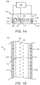
- FIGS. 1A and 1B there are respectively shown a front partially cross-sectional view and a bottom view of a portion of an example apparatus 100 that may be implemented during part of a 3D printing operation.
- the apparatus 100 may include a printhead assembly 102 that may contain a housing 104 supporting a printhead 106.
- the printhead 106 may include multiple nozzles 108 arranged along multiple columns (e.g., two columns along a mono-color ink slot) along most or all of a length of the printhead 106.
- a relatively large number of nozzles 108 positioned in a relatively densely packed arrangement may be provided on the printhead 106 to enable delivery of liquids, e.g., functional agents, from the nozzles 108 at a high resolution, e.g., 600 dpi, 1200 dpi, etc.
- a high resolution e.g. 600 dpi, 1200 dpi, etc.
- the nozzles 108 may be arranged in a staggered fashion along the columns of nozzles 108 as the staggered arrangement may enable the nozzles 108 to print at a relatively higher resolution.
- the nozzles 108 in one column may be aligned with the nozzles 108 in the other column or the nozzles 108 may be arranged in a single column.
- a plurality of printheads 106 may be provided along the housing 104.
- a respective firing element 110 may be provided within each of the nozzles 108.
- the firing elements 110 may be any suitable type of firing element known or as yet to be known to be used in printhead nozzles.
- suitable types of firing elements 110 may include thermal resistors that may become heated to vaporize a functional agent contained in firing chambers of the nozzles 108 on the firing elements 110 and form bubbles that force the functional agent out of bores of the nozzles 108.
- Other examples of suitable types of firing elements 110 may include piezoelectric firing elements that may deform when electricity is applied across the piezoelectric elements, in which the deformation forces a functional agent out of the nozzles 108 through respective bores.
- firing elements 110 may include mechanical inkjets, which may include solenoid valves that may be opened to provide continuous flow of a functional agent, e.g., deposit the functional agent as a continuous inkjet.
- the firing chambers may be supplied with the functional agent from an ink delivery system that may include a reservoir containing the functional agent.
- the firing elements 110 when activated, may cause droplets 112 of a functional agent to be fired out of the nozzles 108 and delivered onto a layer of build material particles 114.
- the layer of build material particles 114 has been depicted with dashed lines to indicate that the layer of build material particles 114 may not form part of the apparatus 100.
- the droplet 112 of the functional agent may follow a flight path 116 from the nozzle 108 to the layer of build material particles 114.
- the droplets 112 fired from the nozzles 108 may each follow a respective flight path 116 from the nozzles 108 to the build material particles 114.
- the printhead assembly 102 may also include an array of light emission devices (or sources) 120 that may each direct a respective light beam 122, which is represented by a dashed line, through a respective flight path 116 of a droplet 112.
- the light emission devices 120 may each be any suitable type of light emitting device that is able to generate and/or direct a focused and/or collimated light beam 122 through the flight path 116 of a droplet 112.
- each of the light emission devices 120 may be a vertical-cavity surface-emitting laser (VCSEL) and the light beam 122 may be a laser beam.
- the light sources 120 may be light emitting diodes, laser diodes, or the like.
- the printhead assembly 102 may further include a plurality of photon detectors (or simply detectors) 124, e.g., photodetectors, optical detectors, etc., that are to receive the light beams 122 from respective ones of the light emission devices 120.
- Each of the photon detectors 124 may be positioned to receive a light beam 122 from a respective light emission device 120.
- each of the light sources 120 may be positioned to direct light beams 122 across the flight paths 116 of droplets 112 fired from each of the nozzles 108 and each of the photon detectors 124 may be positioned to receive the light beams 122 after the light beams have crossed the flight paths 116.
- the light emission devices 120 and the photon detectors 124 may be mounted to the housing 104 via respective supports 126, 128.
- the photon detector 124 may generate an electrical signal, e.g., voltage or current, that may correspond to the intensity of the received light beam 122. That is, the strength of the electrical signal may be higher for received light that has a higher intensity.
- the photon detector 124 may generate data corresponding to the detected light intensity, e.g., may generate data that identifies the intensity of the detected light.
- the photon detector 124 may communicate the generated electrical signal and/or data to a controller 130.
- the intensity of the received light may vary depending upon whether or not a droplet 112 passes through the light beam 122.
- the intensity of the received light may also vary depending upon the composition of the droplet 112 as the droplet 112 passes through the light beam 122.
- the photon detectors 124 may be tested and/or calibrated over time or on a periodic basis to ensure that the photon detectors 124 are operating properly and are accurately detecting the droplets 112.
- the controller 130 may be a semiconductor-based microprocessor, a central processing unit (CPU), an application specific integrated circuit (ASIC), a field-programmable gate array (FPGA), graphics processing unit (GPU), Tensor Processing Unit (TPU), and/or other hardware device and may communicate with the firing elements 110, the light sources 120, and the detectors 124 via communication lines.
- the controller 130 may determine, from the received electrical signal and/or data, whether a droplet 112 was properly fired by a particular nozzle 108, e.g., the nozzle 108 that is to fire droplets 112 along the flight path 116 that intersects the light beam 122.
- the controller 130 may determine that a droplet 112 was properly fired from the particular nozzle 108 if the received electrical signal or data indicates that the intensity of the light beam 122 is below a certain threshold level, which may include an indication that the detector 124 did not receive the light beam 122. Likewise, the controller 130 may determine that a droplet 112 was properly fired from the particular nozzle 108 if the received electrical signal or data indicates that the intensity of the light beam 122 is above the certain threshold level. In other words, the controller 130 may determine that a droplet 112 was properly fired if the droplet 112 is determined to have a composition, that exceeds a certain level
- the controller 130 may additionally determine whether a droplet 112 crossed the light beam 122 within a predefined time frame following activation of the firing element 110. That is, when the controller 130 sends a firing instruction to the firing element 110 of a particular nozzle 108, the controller 130 may also send an activation signal to the light emission device 120 that is to direct a light beam 122 through the flight path 116 of the droplets 112 corresponding to that nozzle 108.
- the activation signal may be kept active for a duration of time that covers a period of time that it normally takes for a droplet 112 or for multiple droplets 112 to be formed and fired from the nozzle 108 and pass through the light beam 122. The duration of time may be determined through testing.
- the controller 130 may determine when the firing instruction was sent to the firing element 110 and when an electrical signal or data was received from the photon detector 124. The controller 130 may determine whether the droplet 112 crossed the light beam 122 within the predetermined time frame based upon when an electrical signal or data was received from the photon detector 124. If the controller 130 determines that the droplet 112 crossed the light beam 122 within the predetermined time frame, the controller 130 may determine that the droplet 112 was properly fired. However, if the controller 130 determines that the droplet 112 did not cross the light beam 122 within the predetermined time frame, the controller 130 may determine that the droplet 112 was improperly fired.
- a droplet 112 may be considered as having been improperly fired if the droplet 112 does not cross the light beam 122 within the predetermined time frame. As set out in claims 1 and 10, a droplet 112 is considered as having been improperly fired if the droplet 122 crosses the light beam 122 within the predetermined time frame but has an improper composition.
- the controller 130 may determine that the nozzle 108 that fired the droplet 112 may be operating improperly or may otherwise be malfunctioning. In response to making this determination, the controller 130 may output an alert such that a user or operator may be notified of the possibility of the improperly operating nozzle 108.
- the controller 130 may implement an operation to mitigate errors caused by the improperly operating nozzle 108 or cease firing of the droplets 112 of the functional agent in response to making this determination.
- the functional agent may be a binding agent that is to cause the build material particles 114 upon which the functional agent has been deposited to bind together.
- the functional agent may be a fusing agent that is to enhance fusing of the build material particles 114 upon which functional agent has been deposited.
- the functional agent when energy is applied, the functional agent may enhance absorption of the energy by the build material particles 114 upon which the functional agent has been deposited.
- the functional agent may be a detailing agent that is to reduce or inhibit fusing of the build material particles 114 upon which the functional agent has been applied.
- the functional agent may be a coloring agent that is to apply color to the build material particles 114.
- the functional agent may change a chemical composition of the build material particles 114 (e.g., for printed metal, black ink providing carbon may become incorporated into a printed stainless steel, ink containing nanoparticles of metal may be locally added into the printed metal (e.g., Cu into Al-alloy, Cr into Ti-alloy), etc.
- the functional agent may include energetics ink, e.g., ink containing compounds that release substantial amounts of energy when they decompose at elevated temperatures as may occur during exposure of build material particles 114 to energy. This additional heat energy may be used for boosting the melting process of the build material particles 114, particularly when the build material particles 114 are metallic particles.
- energetics ink e.g., ink containing compounds that release substantial amounts of energy when they decompose at elevated temperatures as may occur during exposure of build material particles 114 to energy. This additional heat energy may be used for boosting the melting process of the build material particles 114, particularly when the build material particles 114 are metallic particles.
- the type of light beam 122 emitted through the flight paths 116 of the droplets 112 may depend upon the luminescent properties of the droplets 112. That is, for example, in instances in which the droplets 112 are transparent and may thus absorb infrared light, the light beams 122 may be infrared light beams. In other examples in which the droplets 112 are opaque, the light beams 122 may be between the infrared and the ultraviolet spectrums. In one regard, therefore, the type of light beam 122 may be tuned to a spectrum that accurately tracks the luminescent properties of the droplets 112.
- FIG. 1C there is shown a front partially cross-sectional view of the apparatus 100 depicted in FIGS. 1A and 1B according to another example.
- the apparatus 100 depicted in FIG. 1C is similar to the apparatus 100 depicted in FIGS. 1A and 1B except that the path of the light beam 122 in the apparatus 100 depicted in FIG. 1C may reflect off a surface of the layer of build material particles 114. That is, for instance, the light emission devices 120 may be angled to direct the light beams 122 in the manner shown in FIG. 1C and the detectors 124 may also be angled to receive the light beams 122 after the light beams 122 have been reflected off the build material particles 114.
- the intensity levels of the light beams 122 received by the photon detectors 124 may vary depending upon whether droplets 112 of a functional agent have been deposited onto intended locations on the surface of the layer of material particles 114.
- the light emission devices 120 may direct light beams 122 at particular locations with respect to the nozzles 108 such that the locations at which the light beams 122 reflect off the surface of a layer of build material particles 114 are the locations at which the droplets 122 are intended to land on the surface of the layer of build material particles 114.
- the controller 130 may determine whether the droplets 112 have successfully been deposited at their intended locations on the layer of build material particles 114.
- the controller 130 may determine that a nozzle 108 that was instructed to fire the droplets 112 malfunctioned or otherwise operated improperly. As a result, the controller 130 may output an alert to indicate the issue, may implement mitigation operations, and/or may cease production of a 3D object.
- FIGS. 2A and 2B there are respectively shown a front partially cross-sectional view and a cross-sectional side view of another example apparatus 200.
- the apparatus 200 depicted in FIGS. 2A and 2B includes features similar to those contained in the apparatus 100 depicted in FIGS. 1A and 1B .
- the detectors 124 are depicted as being mounted to the same support 126 as the light sources 120. That is, both the array of light sources 120 and the array of detectors 124 are depicted as being positioned on the same side with respect to an array of nozzles 108.
- a detector 124 may detect a light beam 122 emitted from a light source 120 after the light beam 122 has been reflected from a droplet 112 as shown in FIG. 2A .
- the detector 124 may not output a signal or may output a first signal when the detector 124 does not detect the light beam 122 reflected or otherwise emitted from the droplet 112 and the detector 124 may output a second signal when the detector 124 detects the light beam 122 emanating from the droplet 112.
- the controller 130 may determine whether a particular nozzle 108 properly fired a droplet 112 from the received signal from the detector 124.
- FIGS. 2A and 2B a single row of nozzles 108 are depicted. It should, however, be understood that an additional row of nozzles 108 may be provided along the printhead 106 as depicted in FIG. 1B . In this regard, the additional row of nozzles 108 may be aligned with the light sources 120 and the detectors 124 that are not depicted as being aligned with nozzles 108 in FIG. 2B .
- the light sources 120 may emit light beams 122 having wavelengths that may fall within one or more of a visible spectrum, a UV spectrum, and an IR spectrum.
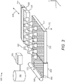
- FIG. 3 there is shown an isometric view of an example 3D printer 300 that may employ either or both of the printhead assemblies 102 depicted in FIGS. 1A-1C and 2A-2B .
- the 3D printer 300 may include a build area platform 302, a build material supply 304 containing build material particles 306, and a spreader 308.
- the build material supply 304 may be a container or surface that is used to position build material particles 306 between the spreader 308 and the build area platform 302.
- the build material supply 304 may be a hopper or a surface upon which the build material particles 306 may be supplied, for instance, from a build material source (not shown) located above the build material supply 304.
- the build material supply 304 may include a mechanism to provide, e.g., move, the build material particles 306 from a storage location to a position to be spread onto the build area platform 302 or a previously formed layer of build material particles 306.
- the build material supply 304 may include a hopper, an auger conveyer, or the like.
- 3D objects or parts are to be generated from the build material particles 306 and the build material particles 306 may be formed of any suitable material including, but not limited to, polymers, metals, and ceramics.
- the build material particles 306 may be in the form of a powder.
- the spreader 308 may move in directions as denoted by the arrow 310, e.g., along the y-axis, over the build material supply 304 and across the build area platform 302 to spread a layer 314 of the build material particles 306 over a surface of the build area platform 302.
- the layer 314 may be formed to a substantially uniform thickness across the build area platform 302.
- the thickness of the layer 314 may range from about 90 ⁇ m to about 110 ⁇ m, although thinner or thicker layers may also be used.
- the thickness of the layer 314 may range from about 20 ⁇ m to about 200 ⁇ m, or from about 50 ⁇ m to about 200 ⁇ m.
- the spreader 308 may also be returned to a position adjacent the build material supply 304 following the spreading of the build material particles 306.
- the spreader 308 may be a doctor blade, roller, a counter rotating roller or any other device suitable for spreading the build material particles 306 over the build area platform 302.
- the 3D printer 300 may also include a plurality of warming devices 320 arranged in an array above or below the build area platform 302.
- Each of the warming devices 320 may be a lamp or other heat source that is used to apply heat onto spread layers 314 of the build material particles 306, for instance, to maintain the build material particles 306 at or above a predetermined threshold temperature.
- the warming devices 320 may maintain the temperatures of the build material particles 306 at a relatively high temperature that facilitates the fusing of the build material particles 306 at selected locations, e.g., the build material particles 306 upon which a particular liquid, such as a fusing agent, has been mixed or applied.
- the 3D printer 300 may further include a first printhead assembly 330 and a second printhead assembly 332, which may both be scanned across the build area platform 302 in both of the directions indicated by the arrow 338, e.g., along the x-axis.
- the first printhead assembly 330 and the second printhead assembly 332 may have features similar to those depicted in FIGS. 1A-1C or FIGS. 2A-2B and may extend a width of the build area platform 302. That is, the nozzles 108 of the printheads 106 in the first printhead assembly 330 and the second printhead assembly 332 may deliver droplets 112 of a functional agent or multiple functional agents across a majority of the surface of a layer 314 of build material particles 306.
- first printhead assembly 330 and the second printhead assembly 332 may not extend the width of the build area platform 302.
- the first printhead assembly 330 and the second printhead assembly 332 may also be scanned along the y-axis to enable the first printhead assembly 330 and the second printhead assembly 332 to be positioned over a majority of the area above the build area platform 302.
- the first printhead assembly 330 and the second printhead assembly 332 may be attached to a moving XY stage or a translational carriage (neither of which is shown) that is used to move the first printhead assembly 330 and the second printhead assembly 332 adjacent to the build area platform 302 in order to deposit respective liquid droplets 112 in intended locations on a layer 314 of the build material particles 306.
- the functional agent is a fusing agent that is to enhance absorption of energy by the build material particles 306 upon which the fusing agent has been deposited.
- a radiation generator 334 may be implemented to apply fusing radiation onto the layer 314 of build materials 306.
- the fusing radiation may be in the form of light, electromagnetic radiation, microwaves, or the like.
- the fusing radiation generator 334 may be activated and moved across the layer 314 of build material particles 306, for instance, along the directions indicated by the arrow 338, to apply fusing radiation in the form of light and/or heat onto the build material particles 306.
- the radiation generator 334 may include a UV, IR or near-IR curing lamp, IR or near-IR light emitting diodes (LED), halogen lamps emitting in the visible and near-IR range, microwaves, or lasers with desirable electromagnetic wavelengths.
- the type of fusing radiation generator 334 may depend, at least in part, on the type of active material used in the functional agents applied onto the layer 314 of build material particles 306.
- the light beams 122 may be composed of radiation having similar types of electromagnetic wavelengths as the fusing radiation generator 334.
- the fusing radiation generator 334 may include the light sources 120 that may generate larger intensities of light to fuse the build material particles 306 and may generate smaller intensities of light to detect the droplets 112.
- the build area platform 302 may be lowered as denoted by the arrow 312, e.g., along the z-axis.
- the spreader 308 may be moved across the build area platform 302 to form a new layer 314 of build material particles 306 on top of the previously formed layer.
- the first printhead assembly 330 and the second printhead assembly 332 may deliver droplets 112 of a functional agent onto respective selected areas of the new layer of build material particles 306.
- the radiation generator 334 may be implemented to apply fusing radiation onto the new layer 314 of the build material particles 306 and the build area platform 302 may be lowered. The above-described process may be repeated until a predetermined number of layers have been formed to fabricate a desired 3D part.
- the 3D printer 300 may include a controller 350 that may control operations of the 3D printer 300 components including the build area platform 302, the build material supply 304, the spreader 308, the warming devices 320, the first printhead assembly 330, the second printhead assembly 332, and the radiation generator 334.
- the controller 350 may control firing elements 110 (not shown) to control various operations of the 3D printer 300 components.
- the controller 350 may be a semiconductor-based microprocessor, a central processing unit (CPU), an application specific integrated circuit (ASIC), a field-programmable gate array (FPGA), graphics processing unit (GPU), Tensor Processing Unit (TPU), and/or other hardware device.
- the controller 350 may be connected to the 3D printer 300 components via communication lines.
- the controller 350 is also depicted as being in communication with a data store 352.
- the data store 352 may include data pertaining to a 3D part to be printed by the 3D printer 300. For instance, the data may include the locations in each build material layer 314 that the first printhead assembly 330 is to deposit droplets of the functional agent.
- the data store 352 may also include instructions for determining when nozzles 108 are functioning improperly based upon signals and/or data received from detectors 124 in the printhead assemblies 330, 332 and for handling determinations of improperly functioning nozzles 108.
- the controller 350 may be equivalent to the controller 130 depicted in FIGS. 1A and 2A . In other examples, the controller 350 may receive data from the controller 130 and they communicate instructions to the controller 130. Various manners in which the controller 130 and/or the controller 350 may operate are described in greater detail herein.
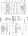
- FIG. 4 there is shown a block diagram of another example apparatus 400, which may also be a 3D fabricating device, a 3D printer, or the like, that may be implemented to fabricate 3D objects from build material particles 114, 306.
- the description of the apparatus 400 is made with reference to FIGS. 1A-1C , 2A-2B , and 3 .
- the apparatus 400 may include a controller 402 that may control operations of the apparatus 400.
- the controller 402 may be a semiconductor-based microprocessor, a central processing unit (CPU), an application specific integrated circuit (ASIC), a field-programmable gate array (FPGA), graphics processing unit (GPU), Tensor Processing Unit (TPU), and/or other hardware device.
- the controller 402 may access a data store 404, which may be a Random Access Memory (RAM), an Electrically Erasable Programmable Read-Only Memory (EEPROM), a storage device, an optical disc, and the like.
- the data store 404 may have stored thereon data pertaining to a 3D object that the apparatus 400 is to fabricate.
- the apparatus 400 may also include an interface 406 through which the controller 402 may communicate instructions to a plurality of components contained in the apparatus 400.
- the interface 406 may be any suitable hardware and/or software through which the controller 402 may communicate the instructions.
- the interface 406 may also enable communication of information from the components to the controller 402.
- the components may include a spreader 410, a printhead motor 412, a plurality of firing elements 110 414-1 to 414-N, a plurality of light sources 416-1 to 416-N, an output device 418, and a plurality of detectors 420-1 to 420-N.
- the spreader 410 may be equivalent to the spreader 308 depicted in FIG. 3 .
- the firing elements 110 414-1 to 414-N may be equivalent to the firing elements 110, the light sources 416-1 to 416-N maybe equivalent to the light sources 120, and the detectors 420-1 to 420-N may be equivalent to the detectors 124 depicted in FIGS. 1A-1C and 2A-2B .
- the variable "N" may represent a value greater than one.
- the apparatus 400 may also include a memory 430 that may have stored thereon machine readable instructions 432-446 (which may also be termed computer readable instructions) that the controller 402 may execute.
- the memory 430 may be an electronic, magnetic, optical, or other physical storage device that contains or stores executable instructions.
- the memory 430 may be, for example, Random Access memory (RAM), an Electrically Erasable Programmable Read-Only Memory (EEPROM), a storage device, an optical disc, and the like.
- RAM Random Access memory
- EEPROM Electrically Erasable Programmable Read-Only Memory
- the memory 430 which may also be referred to as a computer readable storage medium, may be a non-transitory machine-readable storage medium, where the term "non-transitory" does not encompass transitory propagating signals.
- the controller 402 may fetch, decode, and execute the instructions 432 to access 3D object slices, in which each slice may identify (e.g., contain instructions about) a section of a 3D object that is to be formed in a particular layer 314 of build material particles 114, 306.
- the controller 402 may fetch, decode, and execute the instructions 434 to control the spreader 410 to spread build material particles 114, 306 into a layer 314.
- the controller 402 may fetch, decode, and execute the instructions 436 to control the printhead motor 412.
- the controller 402 may fetch, decode, and execute the instructions 438 to activate an actuator 414-1 or multiple firing elements 414-1 to 414-N contained in nozzles 108.
- the controller 402 may fetch, decode, and execute the instructions 440 to activate a light source 416-1 or multiple light sources 416-1 to 416-N.
- the controller 402 may fetch, decode, and execute the instructions 442 to receive signals/data from a detector 420-1 or multiple detectors 420-1 to 420-N.
- the controller 402 may fetch, decode, and execute the instructions 444 to determine whether any of the nozzles 108 failed to fire a droplet 112 as intended.
- the controller 402 may fetch, decode, and execute the instructions 446 to output an instruction regarding a malfunctioning nozzle in response to a determination that the nozzle failed to fire a droplet as intended.
- the computer readable storage medium 430 may be any electronic, magnetic, optical, or other physical storage device that contains or stores executable instructions.
- the computer readable storage medium 430 may be, for example, Random Access Memory (RAM), an Electrically Erasable Programmable Read-Only Memory (EEPROM), a storage device, an optical disc, and the like.
- RAM Random Access Memory
- EEPROM Electrically Erasable Programmable Read-Only Memory
- the computer readable storage medium 430 may be a non-transitory machine-readable storage medium, where the term "non-transitory" does not encompass transitory propagating signals.
- FIG. 5 depicts an example method 500 for detecting a malfunctioning nozzle during a 3D object printing operation with detectors that are mounted to a common housing as a printhead containing the nozzle.
- the description of the method 500 is made with reference to the apparatuses 100, 200, 400 illustrated in FIGS. 1A-1C , 2A-2B , and 4 and the 3D printer 300 illustrated in FIG. 4 for purposes of illustration. It should, however, be understood that apparatuses and 3D printers having other configurations may be implemented to perform the method 500 without departing from a scope of the method 500.
- 3D object slices may be accessed.
- the controller 402 may execute the instructions 432 to access the 3D object slices, in which each slice may identify a section of a 3D object that is to be formed in a particular layer of build material particles 114, 306.
- the controller 402 may access the 3D object slices from the data store 404, from a user input, over a network, etc.
- a layer 314 of build material particles 114, 306 may be spread across the build area platform 302.
- the controller 402 may execute the instructions 434 to control a spreader 308, 410 to spread a pile of build material particles 114, 306 across the build area platform 302 to form the layer 314 of build material particles 114, 306.
- a printhead motor 412 may be controlled to cause a printhead 106, 330, 332 to move across the spread layer 314 of build material particles 114, 306.
- the printhead motor 412 may thus be a motor that may cause a carriage on which the printhead 106, 330, 332 is supported to move across the spread layer 314.
- activation of the printhead motor 412 may cause the printhead 106, 330, 332 to move in the directions denoted by the arrow 338 in FIG. 3 .
- activation of the printhead motor 412 may cause the printhead 106, 330, 332 to move along the y-axis as shown in FIG. 3 .
- the controller 402 may execute the instructions 436 to control the printhead motor 412 and thus the movement of the printhead 106, 330, 332 across the layer 314.
- a plurality of firing elements 414-1 to 414-N may selectively be activated to fire droplets 112 of a functional agent from the nozzles 108 onto selected locations of the layer 314 of build material particles 114, 306. That is, the controller 402 may execute the instructions 438 to selectively activate some or all of the firing elements 110 414-1 to 414-N as the printhead 106, 330, 332 is moved (e.g., scanned) across the layer 314 of build material particles 114, 306 to cause droplets 112 of a functional agent to be fired onto selected locations on the layer 314.
- the controller 402 may selectively activate the firing elements 414-1 to 414-N as the printhead 106, 330, 332 is moved to deliver the droplets 112 of the functional agent onto the locations on the layer 314 that are to be fused together.
- the locations at which the droplets 112 are to be delivered may be defined by the accessed 3D object slices, e.g., the object slice for a current layer 314.
- a plurality of light sources 416-1 to 416-N may be activated to direct respective light beams 122 to intersect with flight paths 116 of the droplets 112 fired from the nozzles 108.
- the controller 402 may execute the instructions 440 to activate the light sources 416-1 to 416-N and to keep the light sources 416-1 to 416-N active for a duration of time that covers a period of time that it normally takes for droplets fired by the firing elements 414-1 to 414-N to pass through the respective light beams 122.
- the controller 402 may activate each of the light sources 416-1 to 416-N.
- the controller 402 may activate those light sources 416-1 to 416-N that direct light beams 122 in the flight paths 116 of the firing elements 414-1 to 416-N that are activated. In these examples, the controller 402 may activate a light source 416-1 when the controller 402 activates an actuator 414-1 that is to fire a droplet 112 through the light beam 122 emitted from the light source 416-1. In addition, the controller 402 may deactivate the light source 416-1 after expiration of a duration of time that covers a period of time that it normally takes for a droplet fired by the actuator 414-1 to pass through the light beam 122.
- the light sources 416-1 to 416-N may direct the light beams 122 to cross the droplet 112 flight paths 116 prior to the droplets 112 reaching the layer of build material particles 114, 306.
- the light sources 416-1 to 416-N may direct the light beams 122 to cross the droplet 112 flight paths 116 on the surface of the layer of build material particles 114, 306. That is, for instance, the light beams 122 may be directed to reflect off the surface of the layer of build material particles 114, 306 at locations on which the droplets 112 are to land.
- the light sources 416-1 to 416-N may move the light beams 122, e.g., scan the light beams 122, in one or more directions, which may enhance detection of the droplets 112.
- the controller 402 may receive signals from the detectors 420-1 to 420-N, in which the signals may correspond to whether or not the droplets 112 were detected to have been fired from the nozzles 108 as intended.
- the detectors 420-1 to 420-N which may also be termed photodetectors, may collect light beams 122 that the light sources 416-1 to 416-N have outputted.
- each of the detectors 420-1 to 420-N may be positioned to collect a light beam 122 emitted from a corresponding light source 416-1 to 416-N, e.g., a first detector 420-1 may be positioned to collect a light beam 122 emitted from a first light source 414-1, a second detector 420-2 may be positioned to collect a light beam 122 emitted from a second light source 414-2, etc.
- light beams 122 originating from a common light source 414-1 may be filtered, for instance, with a collimating mechanism or lens, to be directed to the first detector 420-1, the second detector 420-2, etc.
- Each of the detectors 420-1 to 420-N may generate a signal corresponding to the intensity of the light that the detectors 420-1 to 420-N collect and may send the generated signals to the controller 402.
- a detector 420-1 may generate a first signal in response to the collected light being at a first intensity level, may generate a second signal in response to the collected light being at a second intensity level, and so forth.
- the detector 420-1 may generate a first signal if the light beam 122 directed from the light source 416-1 corresponding to the detector 420-1 is collected without interference as may occur when a droplet 112 does not pass through the light beam 122.
- the detector 420-1 may generate a second signal if the light beam 122 is collected with a relatively small amount of interference as may occur when the droplet 112 is smaller than intended, e.g., has a smaller volume that intended.
- the detector 420-1 may generate a third signal if the light beam 122 is obstructed during collection as may occur when the droplet 112 has an intended volume.
- a determination may be made from the received signals as to whether any of the nozzles 108 malfunctioned. That is, the controller 402 may execute the instructions 444 to determine, from the signals received from the detectors 420-1 to 420-N, whether any of the nozzles 108 failed to fire a droplet 112 as intended.
- the controller 402 may determine that a particular nozzle 108 failed to fire a droplet 112 as intended if a firing signal was sent to the actuator 414-1 of the particular nozzle 108, the light source 416-1 was activated to emit a light beam 122, and the detector 420-1 sent a signal indicative of a droplet 112 either not crossing through the light beam 122 or having an insufficient volume within a certain period of time following the transmission of the firing signal. Thus, for instance, the controller 402 may determine from the signal received from the detector 420-1 that a droplet 112 was either not fired from the particular nozzle 108 or that the fired droplet 112 was not fired as intended.
- the controller 402 may execute the instructions 446 to output an instruction as indicated at block 516.
- the controller 402 may output an instruction to the output device 418 to issue an alert for an operator to be informed that a nozzle has or that multiple nozzles 108 have malfunctioned.
- the controller 402 may cease printing operations until an operator decides to continue with the printing operation.
- the controller 402 may output an instruction that is to cause a mitigation operation to be performed to compensate for the malfunction nozzle or nozzles 108.
- the mitigation operation may include, for instance, implementing another nozzle or multiple other nozzles 108 to deposit droplets 112 of a functional agent onto the locations of the layer of build material particles 114, 306 upon which the malfunctioning nozzle or nozzles 108 were intended to deposit the droplets 112.
- the controller 402 may implement other operations at block 516. That is, FIG. 6 depicts a flow diagram of a method 600 that may be implemented as part of or in place of block 516 in FIG. 5 .
- the controller 402 may determine that a nozzle or that multiple nozzles 108 have malfunctioned.
- the controller 402 may determine a print quality level selected for the 3D object that is in the process of being printed. That is, a user may select to print the 3D object at one of multiple print quality levels, e.g., a high quality level, a low quality level (e.g., a draft mode), etc.
- the print quality at which the 3D object is to be printed may be based upon various considerations, for instance, the criticality of the 3D object, tolerance adherence requirements, etc.
- the controller 402 may determine whether the selected print quality level exceeds a certain print quality level. For instance, the controller 402 may determine at block 606 whether the selected print quality level is the high quality level or the low quality level. In response to a determination that the selected print quality level exceeds the certain print quality level at block 606, e.g., that the 3D object is to be printed at a high quality level, the controller 402 may cease printing of the 3D object as indicated at block 608. That is, the controller 402 may stop activating the firing elements 414-1 to 414-N to thus stop firing of droplets 112 onto the layer of build material particles 114, 306.
- the controller 402 may continue printing of the 3D object as indicated at block 610. That is, the controller 402 may continue activating the firing elements 414-1 to 414-N to thus continue firing droplets 112 onto the layer of build material particles 114, 306 as the printhead 106, 330, 332 is moved across the layer of build material particles 114, 306.
- the 3D object may continue to be fabricated with defects if the selected quality level for the 3D object is low.
- a determination may be made as to whether the method 500 is to be continued at block 518.
- the controller 402 may determine that the method 500 is to be continued in instances in which additional areas of the layer of build material particles 114, 306 are to be fused together, additional sections of the 3D object are to be formed from additional layers of build material particles 114, etc.
- the controller 402 may repeat blocks 508-518 until a determination that the method 500 is to be discontinued is made at block 518, at which the method 500 may end as indicated at block 520.
- blocks 510-518 may be performed each time the firing elements 414-1 to 414-N are activated. In other examples, blocks 510-518 may be performed at predefined periods of time, once for each of the firing elements 414-1 to 414-N during a printing operation, once for each of the firing elements 414-1 to 414-N during an initial activation of the firing elements 414-1 to 414-N for printing onto a newly formed layer of build material particles 114, 306, or the like.
- the detectors 124 may undergo testing and/or calibration operations periodically and/or over time to ensure that the detectors 124, 420-1 to 420-N are operating properly, e.g., accurately detecting the droplet 112.
- Some or all of the operations set forth in the methods 500 and 600 may be contained as programs or subprograms in any desired computer accessible medium.
- the methods 500 and 600 may be embodied by computer programs, which may exist in a variety of forms both active and inactive. For example, they may exist as machine readable instructions, including source code, object code, executable code or other formats. Any of the above may be embodied on a non-transitory computer readable storage medium.
- non-transitory computer readable storage media include computer system RAM, ROM, EPROM, EEPROM, and magnetic or optical disks or tapes. It is therefore to be understood that any electronic device capable of executing the above-described functions may perform those functions enumerated above.
Landscapes
- Engineering & Computer Science (AREA)
- Chemical & Material Sciences (AREA)
- Materials Engineering (AREA)
- Manufacturing & Machinery (AREA)
- Mechanical Engineering (AREA)
- Optics & Photonics (AREA)
- Physics & Mathematics (AREA)
- Health & Medical Sciences (AREA)
- Toxicology (AREA)
- Analytical Chemistry (AREA)
- Automation & Control Theory (AREA)
- Microelectronics & Electronic Packaging (AREA)
- Plasma & Fusion (AREA)
Claims (13)
- Einrichtung (100, 200, 300, 400), die Folgendes umfasst:eine Druckkopfbaugruppe (102, 330, 332), die Folgendes beinhaltet:ein Gehäuse (104);einen Druckkopf (106), der an dem Gehäuse gelagert ist, wobei der Druckkopf Düsen (108) aufweist, die Tröpfchen eines funktionellen Mittels auf eine Schicht von Baumaterialteilchen (114, 306) entlang jeweiliger Flugpfade abfeuern, um Bereiche eines dreidimensionalen (3D) Objekts aus den Baumaterialteilchen auszubilden;eine Anordnung von Lichtemissionsvorrichtungen (120), um jeweilige Lichtstrahlen in den jeweiligen Flugpfaden zu lenken;eine Anordnung von Photonendetektoren (124, 420), wobei jeder Photonendetektor der Anordnung von Photonendetektoren dazu dient, einen Lichtstrahl (122) zu erfassen, der von einer Lichtemissionsvorrichtung der Anordnung von Lichtemissionsvorrichtungen (120) gelenkt wird, wobei die Lichtemissionsvorrichtungen (120) und die Photonendetektoren (124, 420) auf dem Gehäuse gelagert sind; undeinen Controller (130, 350, 402), der zu Folgendem dient:Empfangen von Signalen von den Photonendetektoren;Bestimmen, ob eine beliebige der Düsen (108) gescheitert ist, ein Tröpfchen wie beabsichtigt, abzufeuern, auf der Basis der empfangenen Signale; undAusgeben einer Anweisung in Bezug auf eine fehlerhafte Düse als Reaktion auf eine Bestimmung, dass die fehlerhafte Düse gescheitert ist, ein Tröpfchen wie beabsichtigt, abzufeuern;wobei die Einrichtung (100, 200, 400) dadurch gekennzeichnet ist, dass die Steuerung ferner dazu konfiguriert ist, zu bestimmen, dass eine Düse gescheitert ist, ein Tröpfchen wie beabsichtigt, abzufeuern, mittels Bestimmen, dass eine Düse gescheitert ist, ein Tröpfchen wie beabsichtigt, abzufeuern, als Reaktion auf ein empfangenes Signal, das angibt, dass eine Zusammensetzung eines erfassten Tröpfchens ungeeignet ist.
- Einrichtung (100, 200, 300, 400) nach Anspruch 1, wobei jede der Düsen (108) eine Kammer und ein Abfeuerungselement einschließt, wobei eine Aktivierung des Abfeuerungselements in einer spezifischen Düse dazu dient zu bewirken, dass ein Tröpfchen des Funktionsmittels aus der Kammer der spezifischen Düse abgefeuert wird, und wobei die Lichtemissionsvorrichtung (120), die dazu dient, einen Lichtstrahl (122) in einem Flugpfad der spezifischen Düse zu lenken, dazu dient, mit der Aktivierung des Abfeuerungselements und für eine Zeitdauer, die eine Zeitperiode abdeckt, die normalerweise für ein Tröpfchen benötigt wird, das aus der Kammer abgefeuert wird, um durch den Lichtstrahl (122) hindurch zu gelangen, aktiviert zu werden.
- Einrichtung (100, 200, 300, 400) nach Anspruch 2, wobei die Steuerung dazu konfiguriert ist, zu bestimmen, dass eine Düse (108) gescheitert ist, ein Tröpfchen wie beabsichtigt, abzufeuern, als Reaktion auf eine Bestimmung, dass ein Intensitätsniveau des Lichtstrahls (122), der durch den Flugpfad der Düse gelenkt wird, als ein höherer als ein gewisser Schwellenwert während der Zeitdauer, in der die Lichtemissionsvorrichtung (120) aktiviert ist, erfasst wird.
- Einrichtung (100, 200, 300, 400) nach Anspruch 1, wobei die Steuerung ferner für eines von einem Implementieren eines Abschwächungsvorgangs und eines Stoppens des Druckkopfs von einem Abfeuern von Tröpfchen des Funktionsmittels auf die Schicht von Baumaterialteilchen (114, 306) als Reaktion auf die Bestimmung, dass eine Düse (108) gescheitert ist, ein Tröpfchen wie beabsichtigt, abzufeuern, konfiguriert ist.
- Einrichtung (100, 200, 300, 400) nach Anspruch 1, wobei die Steuerung dazu konfiguriert ist, ein Druckqualitätsniveau zu bestimmen, das für das 3D-Objekt ausgewählt ist, und wobei die Steuerung dazu dient, zu bestimmen, ob eine Herstellung des 3D-Objekts als Reaktion auf eine Bestimmung, dass eine Düse (108) gescheitert ist, ein Tröpfchen wie beabsichtigt, abzufeuern, auf der Basis des bestimmten Druckqualitätsniveaus, das für das 3D-Objekt ausgewählt ist, zu stoppen ist.
- Einrichtung (100, 200, 300, 400) nach Anspruch 1, wobei die Steuerung ferner dazu konfiguriert ist, zu bestimmen, ob eine beliebige der Düsen (108) gescheitert ist, ein Tröpfchen wie beabsichtigt, abzufeuern, auf der Basis einer Bestimmung eines Intensitätsniveaus eines Lichtstrahls (122) einer Zeitabstimmung, zu der ein Lichtstrahl (122) unterbrochen wird, oder beides.
- Einrichtung (100, 200, 300, 400) nach Anspruch 1, wobei die Lichtemissionsvorrichtungen (120) VCSEL-Laserdioden sind.
- Einrichtung (100, 200, 300, 400) nach Anspruch 1, wobei die Anordnung von Lichtemissionsvorrichtungen (120) dazu konfiguriert ist, die jeweiligen Lichtstrahlen (122) an ausgewählten Stellen auf der Schicht von Baumaterialteilchen zu lenken, und wobei die Anordnung von Photonendetektoren dazu dient, die jeweiligen Lichtstrahlen (122) zu erfassen, die von den ausgewählten Stellen auf der Schicht von Baumaterialteilchen reflektiert werden.
- Einrichtung (100, 200, 300, 400) nach Anspruch 1, wobei die Lichtemissionsvorrichtungen (120) beweglich sind, um die Lichtstrahlen (122) zu bewegen, und wobei die Photonendetektoren dazu dienen, die Eigenschaft der Lichtstrahlen zu erfassen, wenn die Lichtstrahlen bewegt werden.
- Verfahren (500), das Folgendes umfasst:Verteilen (504) von Baumaterialteilchen in eine Schicht;Aktivieren der Abfeuerungselemente (508) innerhalb von Kammern von Düsen in einem Druckkopf, um Tröpfchen eines funktionellen Mittels aus den Kammern auf die Schicht von Baumaterialteilchen selektiv abzufeuern, um einen Bereich eines dreidimensionalen (3D) Objekts aus den Baumaterialteilchen auszubilden, wobei der Druckkopf an einem Gehäuse montiert ist;Aktivieren von Lichtquellen (510), um Lichtstrahlen durch Flugpfade der abgefeuerten Tröpfchen zu lenken;Empfangen (512) von Signalen von Detektoren, um die Lichtstrahlen, die Signale, entsprechend ob die Tröpfchen erfasst wurden, die von den Düsen wie beabsichtigt abgefeuert wurden oder nicht, zu erfassen, und wobei die Lichtquellen und Detektoren an dem Gehäuse montiert sind;Bestimmen (514), aus den empfangenen Signalen, ob eine beliebige der Düsen gescheitert ist, ein Tröpfchen wie beabsichtigt, abzufeuern;Ausgeben (516) einer Anweisung in Bezug auf eine fehlerhafte Düse als Reaktion auf eine Bestimmung, dass die fehlerhafte Düse gescheitert ist, ein Tröpfchen wie beabsichtigt, abzufeuern, und wobei das Verfahren dadurch gekennzeichnet ist, dass ein Bestimmen, ob eine beliebige der Düsen gescheitert ist, ein Tröpfchen wie beabsichtigt, abzufeuern, ein Bestimmen umfasst, dass eine Düse gescheitert ist, ein Tröpfchen wie beabsichtigt, abzufeuern, als Reaktion auf ein empfangenes Signal, das angibt, dass eine Zusammensetzung eines erfassten Tröpfchens ungeeignet ist.
- Verfahren nach Anspruch 10, wobei jede der Lichtquellen einem jeweiligen Abfeuerungselement entspricht, wobei das Verfahren ferner umfasst:
Aktivieren der Lichtquellen mit Aktivierung der Abfeuerungselemente, die jeweils den aktivierten Lichtquellen entsprechen, für eine Zeitdauer, die eine Zeitperiode abdeckt, die normalerweise für ein Tröpfchen benötigt wird, das mittels des Abfeuerungselements abgefeuert wird, um durch den Lichtstrahl hindurch zu gelangen, der von den aktivierten Lichtquellen gelenkt wird. - Verfahren nach Anspruch 10, das ferner Folgendes umfasst:Bestimmen, dass eine Düse fehlerhaft ist, aus den empfangenen Signalen;Bestimmen eines Druckqualitätsniveaus, das für das 3D-Objekt ausgewählt ist;Bestimmen, ob das ausgewählte Druckqualitätsniveau ein gewisses Druckqualitätsniveau überschreitet; als Reaktion auf eine Bestimmung, dass das ausgewählte Druckqualitätsniveau ein gewisses Druckqualitätsniveau überschreitet, Beenden einer Aktivierung der Abfeuerungselemente; undals Reaktion auf eine Bestimmung, dass das ausgewählte Druckqualitätsniveau unter das gewisse Druckqualitätsniveau fällt, Fortsetzen einer Aktivierung der Abfeuerungselemente.
- Einrichtung (100, 200, 400) nach Anspruch 1, wobei die Steuerung ferner für Folgendes konfiguriert ist:Bestimmen, dass eine Düse (108) fehlerhaft ist, aus den empfangenen Signalen;Bestimmen eines Druckqualitätsniveaus, das für das 3D-Objekt ausgewählt ist;Bestimmen, ob das ausgewählte Druckqualitätsniveau ein gewisses Druckqualitätsniveau überschreitet; undals Reaktion auf eine Bestimmung, dass das ausgewählte Druckqualitätsniveau ein gewisses Druckqualitätsniveau überschreitet, Ausgeben einer Anweisung ein Abfeuern der Tröpfchen zu beenden;
Applications Claiming Priority (1)
| Application Number | Priority Date | Filing Date | Title |
|---|---|---|---|
| PCT/US2017/028956 WO2018194680A1 (en) | 2017-04-21 | 2017-04-21 | Printhead assembly with light emission devices and photon detectors |
Publications (3)
| Publication Number | Publication Date |
|---|---|
| EP3580042A1 EP3580042A1 (de) | 2019-12-18 |
| EP3580042A4 EP3580042A4 (de) | 2021-04-07 |
| EP3580042B1 true EP3580042B1 (de) | 2023-02-22 |
Family
ID=63855989
Family Applications (1)
| Application Number | Title | Priority Date | Filing Date |
|---|---|---|---|
| EP17906370.6A Active EP3580042B1 (de) | 2017-04-21 | 2017-04-21 | Druckkopfanordnung mit lichtemittierenden vorrichtungen und photonendetektoren |
Country Status (4)
| Country | Link |
|---|---|
| US (1) | US11338517B2 (de) |
| EP (1) | EP3580042B1 (de) |
| CN (1) | CN110325344B (de) |
| WO (1) | WO2018194680A1 (de) |
Families Citing this family (11)
| Publication number | Priority date | Publication date | Assignee | Title |
|---|---|---|---|---|
| DE102017205053A1 (de) * | 2017-03-24 | 2018-09-27 | Eos Gmbh Electro Optical Systems | Belichtungsstrategie in Mehrstrahl-AM-Systemen |
| US20220143910A1 (en) * | 2018-09-26 | 2022-05-12 | Board Of Trustees Of The University Of Arkansas | Resin Extrusion Printhead for 3D Printing |
| US12008745B2 (en) * | 2019-12-09 | 2024-06-11 | Desktop Metal, Inc. | System and methods for printing defect detection |
| AT17186U1 (de) * | 2020-03-11 | 2021-08-15 | Progress Maschinen & Automation Ag | 3D-Druckvorrichtung, insbesondere für die Bauindustrie |
| US12427768B2 (en) * | 2020-06-22 | 2025-09-30 | Hewlett-Packard Development Company, L.P. | Printhead positions |
| US20230311420A1 (en) * | 2020-07-30 | 2023-10-05 | Hewlett-Packard Development Company, L.P. | 3d printing using energy sources |
| WO2022025933A1 (en) * | 2020-07-31 | 2022-02-03 | Hewlett-Packard Development Company, L.P. | Sacrificial parts defined with agents including binders |
| EP4190535A1 (de) * | 2021-12-02 | 2023-06-07 | Quantica GmbH | System und verfahren zur optischen tröpfchenanalyse |
| US12121971B2 (en) | 2022-11-09 | 2024-10-22 | Xerox Corporation | Real-time molten droplet analyzer with spatial modulation in additive manufacturing |
| US12454004B2 (en) | 2022-11-09 | 2025-10-28 | Xerox Corporation | Real-time molten droplet analyzer with spatial modulation in additive manufacturing |
| US20240149355A1 (en) * | 2022-11-09 | 2024-05-09 | Palo Alto Research Center Incorporated | Real-time liquid metal droplet analyzer with spatial modulation in additive manufacturing |
Family Cites Families (17)
| Publication number | Priority date | Publication date | Assignee | Title |
|---|---|---|---|---|
| US6270335B2 (en) | 1995-09-27 | 2001-08-07 | 3D Systems, Inc. | Selective deposition modeling method and apparatus for forming three-dimensional objects and supports |
| US6641246B2 (en) | 2000-02-23 | 2003-11-04 | Seiko Epson Corporation | Detection of non-operating nozzle by light beam passing through aperture |
| US20050018006A1 (en) | 2003-06-27 | 2005-01-27 | Samsung Electronics Co., Ltd. | Method of determining missing nozzles in an inkjet printer |
| US20070024658A1 (en) | 2005-07-28 | 2007-02-01 | Eastman Kodak Company | Apparatus and method for detection of liquid droplets |
| US8177318B2 (en) | 2008-03-25 | 2012-05-15 | Hewlett-Packard Development Company, L.P. | Orifice health detection device |
| US8449068B2 (en) | 2009-02-19 | 2013-05-28 | Hewlett-Packard Development Company, L.P. | Light-scattering drop detector |
| ES2342034T3 (es) | 2008-08-13 | 2010-06-30 | Ricoh Elemex Corporation | Aparato de deteccion de fallo de descarga de liquido, aparato de grabacion por inyeccion de tinta, y procedimiento de deteccion de fallo de descarga de liquido. |
| ES2934103T3 (es) * | 2011-01-31 | 2023-02-16 | Global Filtration Systems Dba Gulf Filtration Systems Inc | Aparato para fabricar objetos tridimensionales a partir de múltiples materiales solidificables |
| WO2012128749A1 (en) | 2011-03-20 | 2012-09-27 | Hewlett-Packard Development Company, L.P. | Drop detection |
| US9134233B2 (en) | 2011-05-31 | 2015-09-15 | Hewlett-Packard Development Company, L.P. | Drop detection assembly and method |
| US9527240B2 (en) * | 2013-03-15 | 2016-12-27 | Stratasys, Inc. | Additive manufacturing system and method for printing three-dimensional parts using velocimetry |
| US11273594B2 (en) * | 2014-01-16 | 2022-03-15 | Hewlett-Packard Development Company, L.P. | Modifying data representing three-dimensional objects |
| JP2015166174A (ja) * | 2014-02-12 | 2015-09-24 | 株式会社リコー | 液滴検出装置及びこれを用いたインクジェット記録装置及び液滴検出方法 |
| WO2016040453A1 (en) | 2014-09-10 | 2016-03-17 | The Exone Company | Three-dimensional printing progress verification methods and apparatuses |
| US9302519B1 (en) * | 2014-12-16 | 2016-04-05 | Xerox Corporation | System for detecting malfunctioning ejectors in three-dimensional object printing using specular reflectance |
| US10195788B2 (en) | 2015-05-29 | 2019-02-05 | Hewlett-Packard Development Company, L.P. | Priming agent distributors while generating three-dimensional objects |
| US10357960B2 (en) * | 2015-10-30 | 2019-07-23 | Nike, Inc. | Three-dimensional curing of a two-dimensionally printed object |
-
2017
- 2017-04-21 WO PCT/US2017/028956 patent/WO2018194680A1/en not_active Ceased
- 2017-04-21 US US16/076,339 patent/US11338517B2/en active Active
- 2017-04-21 EP EP17906370.6A patent/EP3580042B1/de active Active
- 2017-04-21 CN CN201780086335.1A patent/CN110325344B/zh not_active Expired - Fee Related
Also Published As
| Publication number | Publication date |
|---|---|
| WO2018194680A1 (en) | 2018-10-25 |
| US11338517B2 (en) | 2022-05-24 |
| EP3580042A1 (de) | 2019-12-18 |
| CN110325344A (zh) | 2019-10-11 |
| EP3580042A4 (de) | 2021-04-07 |
| CN110325344B (zh) | 2022-03-04 |
| US20210197487A1 (en) | 2021-07-01 |
Similar Documents
| Publication | Publication Date | Title |
|---|---|---|
| EP3580042B1 (de) | Druckkopfanordnung mit lichtemittierenden vorrichtungen und photonendetektoren | |
| US11648732B2 (en) | Indexing in 3D printing | |
| JP4527397B2 (ja) | 固体自由形状製作のための量子化供給装置 | |
| CN102056729B (zh) | 利用连续波紫外光led固化的选择性沉积成形 | |
| EP3436240B1 (de) | Bestimmung des qualitätsniveaus einer baumaterialschicht | |
| EP3687771B1 (de) | Herstellung eines dreidimensionalen objektes | |
| EP3436237B1 (de) | Generative fertigung mit selektiver erwärmung | |
| US20180264737A1 (en) | Determining layer thickness | |
| EP3625031A1 (de) | Temperaturregelung bei der formung von 3d-objekten | |
| US8814311B2 (en) | Inkjet printer and control method for inkjet printer | |
| US12465978B2 (en) | Increasing energy absorption during additive manufacturing | |
| CN120941730A (zh) | 三维对象生产 | |
| WO2020081071A1 (en) | Additive manufacturing | |
| US20220184889A1 (en) | Additive manufacturing machines comprising focused and unfocused energy sources | |
| EP4065346B1 (de) | Generative fertigung mit gleichmässigen eigenschaftsverteilungen | |
| US12502837B2 (en) | Printing with multiple carriages | |
| US20220250319A1 (en) | Additive manufacturing with laser arrays | |
| US20230311411A1 (en) | Dispensing print agent from print bars | |
| JP6866398B2 (ja) | マルチパス液体供給を使用する3d部品制御 |
Legal Events
| Date | Code | Title | Description |
|---|---|---|---|
| STAA | Information on the status of an ep patent application or granted ep patent |
Free format text: STATUS: THE INTERNATIONAL PUBLICATION HAS BEEN MADE |
|
| PUAI | Public reference made under article 153(3) epc to a published international application that has entered the european phase |
Free format text: ORIGINAL CODE: 0009012 |
|
| STAA | Information on the status of an ep patent application or granted ep patent |
Free format text: STATUS: REQUEST FOR EXAMINATION WAS MADE |
|
| 17P | Request for examination filed |
Effective date: 20190719 |
|
| AK | Designated contracting states |
Kind code of ref document: A1 Designated state(s): AL AT BE BG CH CY CZ DE DK EE ES FI FR GB GR HR HU IE IS IT LI LT LU LV MC MK MT NL NO PL PT RO RS SE SI SK SM TR |
|
| AX | Request for extension of the european patent |
Extension state: BA ME |
|
| DAV | Request for validation of the european patent (deleted) | ||
| DAX | Request for extension of the european patent (deleted) | ||
| RIC1 | Information provided on ipc code assigned before grant |
Ipc: B33Y 30/00 20150101ALI20201012BHEP Ipc: B29C 64/393 20170101ALI20201012BHEP Ipc: B29C 64/209 20170101AFI20201012BHEP Ipc: B33Y 10/00 20150101ALI20201012BHEP Ipc: B22F 3/00 20060101ALI20201012BHEP Ipc: B29C 64/165 20170101ALI20201012BHEP Ipc: B33Y 50/02 20150101ALI20201012BHEP |
|
| A4 | Supplementary search report drawn up and despatched |
Effective date: 20210304 |
|
| RIC1 | Information provided on ipc code assigned before grant |
Ipc: B29C 64/393 20170101ALI20210226BHEP Ipc: B29C 64/209 20170101AFI20210226BHEP Ipc: B22F 3/00 20210101ALI20210226BHEP Ipc: B33Y 10/00 20150101ALI20210226BHEP Ipc: B33Y 50/02 20150101ALI20210226BHEP Ipc: B29C 64/165 20170101ALI20210226BHEP Ipc: B33Y 30/00 20150101ALI20210226BHEP |
|
| STAA | Information on the status of an ep patent application or granted ep patent |
Free format text: STATUS: EXAMINATION IS IN PROGRESS |
|
| 17Q | First examination report despatched |
Effective date: 20220405 |
|
| REG | Reference to a national code |
Ref country code: DE Ref legal event code: R079 Ref document number: 602017066305 Country of ref document: DE Free format text: PREVIOUS MAIN CLASS: B29C0064112000 Ipc: B29C0064209000 |
|
| GRAP | Despatch of communication of intention to grant a patent |
Free format text: ORIGINAL CODE: EPIDOSNIGR1 |
|
| STAA | Information on the status of an ep patent application or granted ep patent |
Free format text: STATUS: GRANT OF PATENT IS INTENDED |
|
| RIC1 | Information provided on ipc code assigned before grant |
Ipc: B22F 12/90 20210101ALI20221020BHEP Ipc: B22F 12/53 20210101ALI20221020BHEP Ipc: B22F 10/85 20210101ALI20221020BHEP Ipc: B22F 10/22 20210101ALI20221020BHEP Ipc: B22F 3/00 20060101ALI20221020BHEP Ipc: B33Y 30/00 20150101ALI20221020BHEP Ipc: B29C 64/165 20170101ALI20221020BHEP Ipc: B33Y 50/02 20150101ALI20221020BHEP Ipc: B33Y 10/00 20150101ALI20221020BHEP Ipc: B29C 64/393 20170101ALI20221020BHEP Ipc: B29C 64/209 20170101AFI20221020BHEP |
|
| INTG | Intention to grant announced |
Effective date: 20221121 |
|
| GRAS | Grant fee paid |
Free format text: ORIGINAL CODE: EPIDOSNIGR3 |
|
| GRAA | (expected) grant |
Free format text: ORIGINAL CODE: 0009210 |
|
| STAA | Information on the status of an ep patent application or granted ep patent |
Free format text: STATUS: THE PATENT HAS BEEN GRANTED |
|
| AK | Designated contracting states |
Kind code of ref document: B1 Designated state(s): AL AT BE BG CH CY CZ DE DK EE ES FI FR GB GR HR HU IE IS IT LI LT LU LV MC MK MT NL NO PL PT RO RS SE SI SK SM TR |
|
| REG | Reference to a national code |
Ref country code: GB Ref legal event code: FG4D |
|
| REG | Reference to a national code |
Ref country code: CH Ref legal event code: EP |
|
| REG | Reference to a national code |
Ref country code: AT Ref legal event code: REF Ref document number: 1549253 Country of ref document: AT Kind code of ref document: T Effective date: 20230315 Ref country code: IE Ref legal event code: FG4D |
|
| REG | Reference to a national code |
Ref country code: DE Ref legal event code: R096 Ref document number: 602017066305 Country of ref document: DE |
|
| REG | Reference to a national code |
Ref country code: LT Ref legal event code: MG9D |
|
| REG | Reference to a national code |
Ref country code: NL Ref legal event code: MP Effective date: 20230222 |
|
| REG | Reference to a national code |
Ref country code: AT Ref legal event code: MK05 Ref document number: 1549253 Country of ref document: AT Kind code of ref document: T Effective date: 20230222 |
|
| PG25 | Lapsed in a contracting state [announced via postgrant information from national office to epo] |
Ref country code: RS Free format text: LAPSE BECAUSE OF FAILURE TO SUBMIT A TRANSLATION OF THE DESCRIPTION OR TO PAY THE FEE WITHIN THE PRESCRIBED TIME-LIMIT Effective date: 20230222 Ref country code: PT Free format text: LAPSE BECAUSE OF FAILURE TO SUBMIT A TRANSLATION OF THE DESCRIPTION OR TO PAY THE FEE WITHIN THE PRESCRIBED TIME-LIMIT Effective date: 20230622 Ref country code: NO Free format text: LAPSE BECAUSE OF FAILURE TO SUBMIT A TRANSLATION OF THE DESCRIPTION OR TO PAY THE FEE WITHIN THE PRESCRIBED TIME-LIMIT Effective date: 20230522 Ref country code: NL Free format text: LAPSE BECAUSE OF FAILURE TO SUBMIT A TRANSLATION OF THE DESCRIPTION OR TO PAY THE FEE WITHIN THE PRESCRIBED TIME-LIMIT Effective date: 20230222 Ref country code: LV Free format text: LAPSE BECAUSE OF FAILURE TO SUBMIT A TRANSLATION OF THE DESCRIPTION OR TO PAY THE FEE WITHIN THE PRESCRIBED TIME-LIMIT Effective date: 20230222 Ref country code: LT Free format text: LAPSE BECAUSE OF FAILURE TO SUBMIT A TRANSLATION OF THE DESCRIPTION OR TO PAY THE FEE WITHIN THE PRESCRIBED TIME-LIMIT Effective date: 20230222 Ref country code: HR Free format text: LAPSE BECAUSE OF FAILURE TO SUBMIT A TRANSLATION OF THE DESCRIPTION OR TO PAY THE FEE WITHIN THE PRESCRIBED TIME-LIMIT Effective date: 20230222 Ref country code: ES Free format text: LAPSE BECAUSE OF FAILURE TO SUBMIT A TRANSLATION OF THE DESCRIPTION OR TO PAY THE FEE WITHIN THE PRESCRIBED TIME-LIMIT Effective date: 20230222 Ref country code: AT Free format text: LAPSE BECAUSE OF FAILURE TO SUBMIT A TRANSLATION OF THE DESCRIPTION OR TO PAY THE FEE WITHIN THE PRESCRIBED TIME-LIMIT Effective date: 20230222 |
|
| PGFP | Annual fee paid to national office [announced via postgrant information from national office to epo] |
Ref country code: DE Payment date: 20230321 Year of fee payment: 7 |
|
| PG25 | Lapsed in a contracting state [announced via postgrant information from national office to epo] |
Ref country code: SE Free format text: LAPSE BECAUSE OF FAILURE TO SUBMIT A TRANSLATION OF THE DESCRIPTION OR TO PAY THE FEE WITHIN THE PRESCRIBED TIME-LIMIT Effective date: 20230222 Ref country code: PL Free format text: LAPSE BECAUSE OF FAILURE TO SUBMIT A TRANSLATION OF THE DESCRIPTION OR TO PAY THE FEE WITHIN THE PRESCRIBED TIME-LIMIT Effective date: 20230222 Ref country code: IS Free format text: LAPSE BECAUSE OF FAILURE TO SUBMIT A TRANSLATION OF THE DESCRIPTION OR TO PAY THE FEE WITHIN THE PRESCRIBED TIME-LIMIT Effective date: 20230622 Ref country code: GR Free format text: LAPSE BECAUSE OF FAILURE TO SUBMIT A TRANSLATION OF THE DESCRIPTION OR TO PAY THE FEE WITHIN THE PRESCRIBED TIME-LIMIT Effective date: 20230523 Ref country code: FI Free format text: LAPSE BECAUSE OF FAILURE TO SUBMIT A TRANSLATION OF THE DESCRIPTION OR TO PAY THE FEE WITHIN THE PRESCRIBED TIME-LIMIT Effective date: 20230222 |
|
| PG25 | Lapsed in a contracting state [announced via postgrant information from national office to epo] |
Ref country code: SM Free format text: LAPSE BECAUSE OF FAILURE TO SUBMIT A TRANSLATION OF THE DESCRIPTION OR TO PAY THE FEE WITHIN THE PRESCRIBED TIME-LIMIT Effective date: 20230222 Ref country code: RO Free format text: LAPSE BECAUSE OF FAILURE TO SUBMIT A TRANSLATION OF THE DESCRIPTION OR TO PAY THE FEE WITHIN THE PRESCRIBED TIME-LIMIT Effective date: 20230222 Ref country code: EE Free format text: LAPSE BECAUSE OF FAILURE TO SUBMIT A TRANSLATION OF THE DESCRIPTION OR TO PAY THE FEE WITHIN THE PRESCRIBED TIME-LIMIT Effective date: 20230222 Ref country code: DK Free format text: LAPSE BECAUSE OF FAILURE TO SUBMIT A TRANSLATION OF THE DESCRIPTION OR TO PAY THE FEE WITHIN THE PRESCRIBED TIME-LIMIT Effective date: 20230222 Ref country code: CZ Free format text: LAPSE BECAUSE OF FAILURE TO SUBMIT A TRANSLATION OF THE DESCRIPTION OR TO PAY THE FEE WITHIN THE PRESCRIBED TIME-LIMIT Effective date: 20230222 |
|
| REG | Reference to a national code |
Ref country code: DE Ref legal event code: R097 Ref document number: 602017066305 Country of ref document: DE |
|
| PG25 | Lapsed in a contracting state [announced via postgrant information from national office to epo] |
Ref country code: SK Free format text: LAPSE BECAUSE OF FAILURE TO SUBMIT A TRANSLATION OF THE DESCRIPTION OR TO PAY THE FEE WITHIN THE PRESCRIBED TIME-LIMIT Effective date: 20230222 |
|
| REG | Reference to a national code |
Ref country code: CH Ref legal event code: PL |
|
| PG25 | Lapsed in a contracting state [announced via postgrant information from national office to epo] |
Ref country code: LU Free format text: LAPSE BECAUSE OF NON-PAYMENT OF DUE FEES Effective date: 20230421 |
|
| PLBE | No opposition filed within time limit |
Free format text: ORIGINAL CODE: 0009261 |
|
| STAA | Information on the status of an ep patent application or granted ep patent |
Free format text: STATUS: NO OPPOSITION FILED WITHIN TIME LIMIT |
|
| REG | Reference to a national code |
Ref country code: BE Ref legal event code: MM Effective date: 20230430 |
|
| PG25 | Lapsed in a contracting state [announced via postgrant information from national office to epo] |
Ref country code: MC Free format text: LAPSE BECAUSE OF FAILURE TO SUBMIT A TRANSLATION OF THE DESCRIPTION OR TO PAY THE FEE WITHIN THE PRESCRIBED TIME-LIMIT Effective date: 20230222 |
|
| GBPC | Gb: european patent ceased through non-payment of renewal fee |
Effective date: 20230522 |
|
| 26N | No opposition filed |
Effective date: 20231123 |
|
| PG25 | Lapsed in a contracting state [announced via postgrant information from national office to epo] |
Ref country code: SI Free format text: LAPSE BECAUSE OF FAILURE TO SUBMIT A TRANSLATION OF THE DESCRIPTION OR TO PAY THE FEE WITHIN THE PRESCRIBED TIME-LIMIT Effective date: 20230222 Ref country code: MC Free format text: LAPSE BECAUSE OF FAILURE TO SUBMIT A TRANSLATION OF THE DESCRIPTION OR TO PAY THE FEE WITHIN THE PRESCRIBED TIME-LIMIT Effective date: 20230222 Ref country code: LI Free format text: LAPSE BECAUSE OF NON-PAYMENT OF DUE FEES Effective date: 20230430 Ref country code: FR Free format text: LAPSE BECAUSE OF NON-PAYMENT OF DUE FEES Effective date: 20230422 Ref country code: CH Free format text: LAPSE BECAUSE OF NON-PAYMENT OF DUE FEES Effective date: 20230430 |
|
| REG | Reference to a national code |
Ref country code: IE Ref legal event code: MM4A |
|
| PG25 | Lapsed in a contracting state [announced via postgrant information from national office to epo] |
Ref country code: BE Free format text: LAPSE BECAUSE OF NON-PAYMENT OF DUE FEES Effective date: 20230430 |
|
| PG25 | Lapsed in a contracting state [announced via postgrant information from national office to epo] |
Ref country code: IE Free format text: LAPSE BECAUSE OF NON-PAYMENT OF DUE FEES Effective date: 20230421 |
|
| PG25 | Lapsed in a contracting state [announced via postgrant information from national office to epo] |
Ref country code: IE Free format text: LAPSE BECAUSE OF NON-PAYMENT OF DUE FEES Effective date: 20230421 Ref country code: GB Free format text: LAPSE BECAUSE OF NON-PAYMENT OF DUE FEES Effective date: 20230522 |
|
| PG25 | Lapsed in a contracting state [announced via postgrant information from national office to epo] |
Ref country code: IT Free format text: LAPSE BECAUSE OF FAILURE TO SUBMIT A TRANSLATION OF THE DESCRIPTION OR TO PAY THE FEE WITHIN THE PRESCRIBED TIME-LIMIT Effective date: 20230222 |
|
| REG | Reference to a national code |
Ref country code: DE Ref legal event code: R119 Ref document number: 602017066305 Country of ref document: DE |
|
| PG25 | Lapsed in a contracting state [announced via postgrant information from national office to epo] |
Ref country code: BG Free format text: LAPSE BECAUSE OF FAILURE TO SUBMIT A TRANSLATION OF THE DESCRIPTION OR TO PAY THE FEE WITHIN THE PRESCRIBED TIME-LIMIT Effective date: 20230222 |
|
| PG25 | Lapsed in a contracting state [announced via postgrant information from national office to epo] |
Ref country code: BG Free format text: LAPSE BECAUSE OF FAILURE TO SUBMIT A TRANSLATION OF THE DESCRIPTION OR TO PAY THE FEE WITHIN THE PRESCRIBED TIME-LIMIT Effective date: 20230222 |
|
| PG25 | Lapsed in a contracting state [announced via postgrant information from national office to epo] |
Ref country code: DE Free format text: LAPSE BECAUSE OF NON-PAYMENT OF DUE FEES Effective date: 20241105 |
|
| PG25 | Lapsed in a contracting state [announced via postgrant information from national office to epo] |
Ref country code: DE Free format text: LAPSE BECAUSE OF NON-PAYMENT OF DUE FEES Effective date: 20241105 |
|
| PG25 | Lapsed in a contracting state [announced via postgrant information from national office to epo] |
Ref country code: CY Free format text: LAPSE BECAUSE OF FAILURE TO SUBMIT A TRANSLATION OF THE DESCRIPTION OR TO PAY THE FEE WITHIN THE PRESCRIBED TIME-LIMIT; INVALID AB INITIO Effective date: 20170421 |
|
| PG25 | Lapsed in a contracting state [announced via postgrant information from national office to epo] |
Ref country code: HU Free format text: LAPSE BECAUSE OF FAILURE TO SUBMIT A TRANSLATION OF THE DESCRIPTION OR TO PAY THE FEE WITHIN THE PRESCRIBED TIME-LIMIT; INVALID AB INITIO Effective date: 20170421 |
|
| PG25 | Lapsed in a contracting state [announced via postgrant information from national office to epo] |
Ref country code: TR Free format text: LAPSE BECAUSE OF FAILURE TO SUBMIT A TRANSLATION OF THE DESCRIPTION OR TO PAY THE FEE WITHIN THE PRESCRIBED TIME-LIMIT Effective date: 20230222 |