EP3580130B1 - Doppelfass für gefahrengüter - Google Patents
Doppelfass für gefahrengüter Download PDFInfo
- Publication number
- EP3580130B1 EP3580130B1 EP18707633.6A EP18707633A EP3580130B1 EP 3580130 B1 EP3580130 B1 EP 3580130B1 EP 18707633 A EP18707633 A EP 18707633A EP 3580130 B1 EP3580130 B1 EP 3580130B1
- Authority
- EP
- European Patent Office
- Prior art keywords
- barrel
- double
- wall thickness
- area
- inner barrel
- Prior art date
- Legal status (The legal status is an assumption and is not a legal conclusion. Google has not performed a legal analysis and makes no representation as to the accuracy of the status listed.)
- Active
Links
Images

Classifications
-
- B—PERFORMING OPERATIONS; TRANSPORTING
- B65—CONVEYING; PACKING; STORING; HANDLING THIN OR FILAMENTARY MATERIAL
- B65D—CONTAINERS FOR STORAGE OR TRANSPORT OF ARTICLES OR MATERIALS, e.g. BAGS, BARRELS, BOTTLES, BOXES, CANS, CARTONS, CRATES, DRUMS, JARS, TANKS, HOPPERS, FORWARDING CONTAINERS; ACCESSORIES, CLOSURES, OR FITTINGS THEREFOR; PACKAGING ELEMENTS; PACKAGES
- B65D11/00—Containers having bodies formed by interconnecting or uniting two or more rigid, or substantially rigid, components made wholly or mainly of plastics material
- B65D11/16—Containers having bodies formed by interconnecting or uniting two or more rigid, or substantially rigid, components made wholly or mainly of plastics material with double walls
-
- B—PERFORMING OPERATIONS; TRANSPORTING
- B65—CONVEYING; PACKING; STORING; HANDLING THIN OR FILAMENTARY MATERIAL
- B65D—CONTAINERS FOR STORAGE OR TRANSPORT OF ARTICLES OR MATERIALS, e.g. BAGS, BARRELS, BOTTLES, BOXES, CANS, CARTONS, CRATES, DRUMS, JARS, TANKS, HOPPERS, FORWARDING CONTAINERS; ACCESSORIES, CLOSURES, OR FITTINGS THEREFOR; PACKAGING ELEMENTS; PACKAGES
- B65D11/00—Containers having bodies formed by interconnecting or uniting two or more rigid, or substantially rigid, components made wholly or mainly of plastics material
- B65D11/02—Containers having bodies formed by interconnecting or uniting two or more rigid, or substantially rigid, components made wholly or mainly of plastics material of curved cross-section
- B65D11/06—Drums or barrels
- B65D11/08—Arrangements of filling or discharging apertures
-
- B—PERFORMING OPERATIONS; TRANSPORTING
- B65—CONVEYING; PACKING; STORING; HANDLING THIN OR FILAMENTARY MATERIAL
- B65D—CONTAINERS FOR STORAGE OR TRANSPORT OF ARTICLES OR MATERIALS, e.g. BAGS, BARRELS, BOTTLES, BOXES, CANS, CARTONS, CRATES, DRUMS, JARS, TANKS, HOPPERS, FORWARDING CONTAINERS; ACCESSORIES, CLOSURES, OR FITTINGS THEREFOR; PACKAGING ELEMENTS; PACKAGES
- B65D25/00—Details of other kinds or types of rigid or semi-rigid containers
- B65D25/20—External fittings
- B65D25/24—External fittings for spacing bases of containers from supporting surfaces, e.g. legs
Definitions
- the invention relates to a double drum for dangerous goods, comprising an outer drum made of plastic and an inner drum made of plastic received in the outer drum.
- Such a double barrel is available as a combination barrel from the EP 2 896 575 A1 known by the same applicant.
- This combination barrel has the advantage of being light, has a simple structure and is easy to manufacture using a blow molding process. For dangerous goods, such as acids, etc., such a barrel must have high stability and increased operational reliability for transport.
- the US 9 162 816 B1 describes a double tank arrangement with transport grooves and lifting eyes.
- the EP 0 333 544 A1 describes a double-walled barrel that can be stacked with similar barrels.
- the wall of the outer barrel in the area of the circumferential plastic weld seam is thicker by a factor of 1.5 to 2.0 than the wall thickness of the outer barrel in the middle area of the height of the outer barrel in the standing state.
- the annular welding surface is considerably enlarged and the stability of the body of the outer barrel, which is composed of the first barrel part and the second barrel part, is increased. In this way, forces that impinge on the upper, second barrel part at an angle can be safely absorbed and the outer barrel can be prevented from tearing open, even with great forces.
- the thickening at the connection areas of the weld seam preferably protrudes exclusively inward, so that the outer shape of the double barrel does not show the thickening. This is advantageous for handling the double barrel.
- a further development is characterized in that the weld seam produced by fusion welding is arranged as close as possible to an upper panel of the second grip part, preferably at a distance of 2 to 3 times the wall thickness of the upper panel.
- the body of the outer barrel is particularly stable, so that only slight bending and shear forces act on the weld seam, which reduces the risk of the weld seam tearing open.
- an elastic washer is arranged between the bottom of the top and the top of the inner barrel.
- This elastic washer elastically absorbs forces that can act on this sensitive connection point between the top and the top of the inner barrel.
- This annular disk is preferably made of an elastic foam material so that any liquid residues that may be spilled are sucked up when pouring out.
- a connecting piece of at least one container opening of the inner barrel is firmly connected to an upper floor of the outer barrel by means of a fixing ring.
- the inner barrel is fixed to the outer barrel, making the entire double barrel more stable.
- two container openings are formed on the inner barrel and the associated nozzles are correspondingly fastened with a fixing ring each, so that as a result of the symmetrical structure, forces acting are distributed symmetrically.
- a bottom of the inner barrel is held at a predetermined distance from a bottom of the outer barrel, preferably 2 to 3 times the wall thickness of the bottom of the inner barrel.
- an air envelope in the manner of an air cushion is present between the inner surface of the outer barrel and the outer surface of the inner barrel. In the event of a sudden impact on the outer barrel, the impact force is cushioned by displacement of the air, whereby the inner barrel is protected.
- Another advantageous measure provides that the outer dimension of the inner barrel in the central area of the jacket is smaller than the inner dimension of the outer barrel in this area by an amount corresponding to 0.8 to 1.2 times the wall thickness of the outer barrel. This also results in a jacket-shaped air envelope which is cushioned by the air in the air envelope in the event of sudden impacts on the jacket of the outer barrel.
- the wall thickness of the inner barrel in the middle area of the jacket of the inner barrel is at least 2 mm, with a volume of approx. 200 l of the inner barrel. In this way, a stable, yet lightweight construction is achieved.
- the ratio of the wall thickness of the outer barrel to the wall thickness of the inner barrel at the level of the middle of the double barrel is in the range from 2.7 to 2.3 to 1, with the wall thickness of the outer barrel remaining constant in the middle area of its shell.
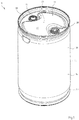
- Figure 1 shows an embodiment of the double barrel in a perspective view.
- This double barrel is a further development of the EP 2 896 575 A1 by the same applicant described combination barrel. Reference is made to this patent application in particular with regard to the production process using the plastic blow molding process.
- the double barrel 10 shown comprises an outer barrel 14 made of plastic, in which an inner barrel 12 (see FIG Figure 2 ) is almost flush.
- This outer barrel 14 is composed of a first barrel part 20, which comprises a shell 21 and a bottom part 23, which is approximately cylindrical over most of its length, and a second barrel part 22 which is placed on the first barrel part 20 and welded to it.
- a ventilation valve 24 and filling openings 26, 28 are provided, which lead through an upper floor 36 in the second barrel part 22.
- the plastic used for the outer barrel 14 and the inner barrel 12 is polyethylene.
- Figure 2 shows a view of the double barrel 10 partially cut along a line of symmetry m.
- the inner barrel 12 is received in the outer barrel 14.
- the outer barrel 14 is composed of the first barrel part 20 and the second barrel part 22, which are connected to one another with respective connecting areas 33, 35 at a welding point 34 by means of fusion welding, also called mirror welding.
- a standing edge 37 is formed in the lower section of the first grip part 20.
- the second barrel part 22 comprises an upper stacking edge 32 in which the standing edge 37 of a further double barrel can be received for stacking.
- On the double barrel 10 can Considerable forces act during transport or handling, shown as arrows A, B, C, D in the Figure 2 are shown.
- the double barrel 10 is characterized by high stability and high operational reliability, for which purpose various technical measures have been taken.
- a force is applied in the direction of the arrow A, ie in the direction diagonally to the double drum 10 and in the direction of the stacking edge 32, the latter can deform and considerable forces occur at the circumferential weld 34, which can cause this weld 34 to tear.
- connection areas 33, 35 of the outer shell 14 are approximately 1.5 to 2.0 times thicker than the usual wall thickness of the outer shell 14 approximately in the middle of the height of the outer shell 14
- the wall thickness of the outer barrel there is typically 4 to 5 mm.
- this welding point 34 is formed as close as possible to the top floor 36 of the second grip part 22, preferably at a distance of 2 to 3 times the wall thickness of the top floor 36, which is typically 4 to 5 mm.
- the outer barrel 14 is particularly mechanically stable, as a result of which a weld seam arranged there can absorb relatively large forces.
- An elastic annular disk 40 is arranged around the container opening 26 between the top floor 36 and an upper side 41 of the inner barrel 12.
- This elastic ring disk 40 is preferably made of foam material, which gives it its elasticity.
- This elastic annular disk 40 can in particular absorb forces in the direction of arrow B, so that external forces are not easily transmitted directly to the inner barrel 12 via the upper side 41. In the version with foam material, this annular disk 40 can also absorb spilled liquid residues and thus keep the inner area between inner barrel 12 and outer barrel 14 dry.
- a connecting piece 42 is formed which is guided through the top bottom 36 and which is firmly connected to the top bottom 36 by means of a fixing ring 44.
- This fixation of the inner barrel 12 on the top floor 36 preferably by means of a screw connection, improves stability against forces acting in the direction of the arrow B, preferably in cooperation with the elastic annular disk 40.
- two container openings 26, 28 are formed, whereby a symmetrical structure is given and forces acting are distributed symmetrically.
- the connecting piece 42 can be closed by a stopper 45.
- a bottom 46 of the inner barrel 12 is held at a predetermined distance a from a bottom 48 of the outer barrel 14.
- This distance a should be in the range of 2 to 3 times the wall thickness of the sub-floor 46 of the inner barrel 12.
- an air envelope is present between the inner barrel 12 and the outer barrel 14 in the manner of an air cushion.
- the air in this air cushion is displaced and the impact force is cushioned, whereby the inner barrel 12 is protected.
- Measures for generating an air cushion can also be taken in the area of the jacket 21 of the double barrel 10.
- the outer dimension of the inner barrel 12 in the area of the jacket 21 of the double barrel 10 is smaller by an amount corresponding to 0.8 to 1.2 times the wall thickness of the outer barrel 14 than the inner dimension of the outer barrel 14 in this area.
- the ring-shaped, air-filled space formed by the structural measures acts like an air cushion with a valve and dampens shock-like forces.
- the outer dimension of the inner container defined in this way interacts advantageously with the wall reinforcement at the weld seam and makes it easier to insert the inner container into the outer container.
- Another measure is characterized in that the wall thickness of the inner barrel 12 tapers evenly from top to bottom in the area of the jacket 21 of the double barrel 10 in a ratio of 2.5 to 1.8 to 1 when it is upright. In the upper area, the stability of the inner barrel 12 is improved and as a result of the tapering, plastic material can be saved.
- the wall thickness of the outer barrel 14 at the level of the middle of the double barrel 10 is typically in the range from 4 to 5 mm and is approximately constant in the area of the jacket 21.
- the ratio of the wall thickness of the outer barrel 14 to the wall thickness of the inner barrel 12 at the level of the middle of the double barrel 10 is in the range from 2.7 to 2.3 to 1.
- the double barrel 10 is preferably produced by a plastic blow molding process.
- the outer barrel 14 is formed from a plastic tube, the material thickening being formed at the connecting areas 33, 35 during the controlled forming of the top floor 36.
- the closed outer barrel 14 is then separated at the later welding point 34 and the inner barrel 12, which is also produced using the blow molding process, is used.
- the welding surfaces of the connection areas 33, 35 are melted by means of a welding mirror, the welding mirror is removed and the first grip part 20 is permanently connected to the second grip part 22.
Landscapes
- Engineering & Computer Science (AREA)
- Mechanical Engineering (AREA)
- Rigid Containers With Two Or More Constituent Elements (AREA)
- Details Of Rigid Or Semi-Rigid Containers (AREA)
- Containers Having Bodies Formed In One Piece (AREA)
- Blow-Moulding Or Thermoforming Of Plastics Or The Like (AREA)
- Packages (AREA)
- Lining Or Joining Of Plastics Or The Like (AREA)
- Tires In General (AREA)
- Closures For Containers (AREA)
Description
- Die Erfindung betrifft ein Doppelfass für Gefahrengüter, umfassend ein Außenfass aus Kunststoff und ein in dem Außenfass aufgenommenes Innenfass aus Kunststoff.
- Ein derartiges Doppelfass ist als Kombinationsfass aus der
EP 2 896 575 A1 desselben Anmelders bekannt. Dieses Kombinationsfass hat den Vorteil eines leichten Gewichtes, ist einfach aufgebaut und leicht durch ein Blasformverfahren herstellbar. Für Gefahrengüter, beispielsweise Säuren etc. muss ein solches Fass für den Transport hohe Stabilität und erhöhte Betriebssicherheit besitzen. - Die
US 9 162 816 B1 - Die
EP 0 333 544 A1 beschreibt ein doppelwandiges Fass, das mit gleichartigen Fässern stapelbar ist. - Keines der vorgenannten Dokumente
EP 2 896 575 A1 ,US 9 162 816 B1 EP 0 333 544 A1 beschreibt die Verdickung im Bereich der Verbindungsbereiche, wie dies die vorliegende Erfindung vorsieht. - Es ist Aufgabe der Erfindung, ein Doppelfass für Gefahrengüter anzugeben, welches unter Beibehaltung einer leichten Bauweise eine hohe Stabilität und Betriebssicherheit besitzt.
- Ein solches Doppelfass für Gefahrengüter ist durch die Kombination der Merkmale des Anspruchs 1 definiert. Vorteilhafte Weiterbildungen sind in den abhängigen Ansprüchen genannt.
- Gemäß der Erfindung ist bei dem Doppelfass die Wand des Außenfasses im Bereich der umlaufenden Kunststoff-Schweißnaht um den Faktor 1,5 bis 2,0 dicker als die Wanddicke des Außenfasses im mittleren Bereich der Höhe des Außenfasses im stehenden Zustand. Durch diese konstruktive Maßnahme wird die ringförmige Schweißfläche erheblich vergrößert und die Stabilität des aus dem ersten Fassteil und dem zweiten Fassteil zusammengesetzten Körpers des Außenfasses erhöht. Auf diese Weise können Kräfte, die in Richtung schräg auf das obere, zweite Fassteil auftreffen, sicher abgefangen und ein Aufreißen des Außenfasses auch bei großen Kräften vermieden werden. Die Verdickung an den Verbindungsbereichen der Schweißnaht ragt vorzugsweise ausschließlich nach innen, so dass die äußere Form des Doppelfasses die Verdickung nicht zeigt. Dies ist für das Handling des Doppelfasses vorteilhaft.
- Eine Weiterbildung zeichnet sich dadurch aus, dass die durch Aufschmelz-Schweißen erzeugte Schweißnaht möglichst nah an einem Oberboden des zweiten Fassteils angeordnet ist, vorzugsweise in einem Abstand vom 2 bis 3-fachen der Wanddicke des Oberbodens. In diesem Bereich, nahe dem Oberboden, ist der Körper des Außenfasses besonders stabil, so dass auf die Schweißnaht nur geringe Biege- und Scherkräfte einwirken, wodurch die Gefahr eines Aufreißens an der Schweißnaht vermindert wird.
- Eine andere Weiterbildung sieht vor, dass um mindestens eine Behälteröffnung im Oberboden des zweiten Fassteils eine elastische Ringscheibe zwischen der Unterseite des Oberbodens und der Oberseite des Innenfasses angeordnet ist. Diese elastische Ringscheibe fängt Kräfte, die auf diese empfindliche Verbindungsstelle zwischen Oberboden und Oberseite des Innenfasses einwirken können, elastisch ab. Vorzugsweise ist diese Ringscheibe aus einem elastischen Schaummaterial gefertigt, so dass beim Ausgießen eventuell verschüttete Flüssigkeitsreste aufgesaugt werden.
- Eine vorteilhafte Weiterentwicklung sieht vor, dass ein Stutzen mindestens einer Behälteröffnung des Innenfasses mittels eines Fixierringes fest mit einem Oberboden des Außenfasses verbunden ist. Auf diese Weise wird das Innenfass am Außenfass fixiert, wodurch das gesamte Doppelfass an Stabilität gewinnt. Vorzugsweise sind zwei Behälteröffnungen am Innenfass ausgebildet und entsprechend werden die zugehörigen Stutzen mit jeweils einem Fixierring befestigt, so dass in Folge des symmetrischen Aufbaus sich einwirkende Kräfte symmetrisch verteilen.
- Vorteilhaft ist, wenn bei der festen Verbindung des Innenfasses mit dem Oberboden des Außenfasses im Leerzustand des Innenfasses ein Unterboden des Innenfasses in einem vorgegebenen Abstand zu einem Unterboden des Außenfasses gehalten ist, vorzugsweise dem 2 bis 3-Fachen der Wanddicke des Unterbodens des Innenfasses. Bei dieser konstruktiven Ausgestaltung ist zwischen Innenoberfläche des Außenfasses und Außenoberfläche des Innenfasses eine Lufthülle nach Art eines Luftkissens vorhanden. Bei einem plötzlichen Stoß auf das Außenfass wird durch Verdrängung der Luft die Stoßkraft abgefedert, wodurch das Innenfass geschützt ist.
- Eine andere vorteilhafte Maßnahme sieht vor, dass das Außenmaß des Innenfasses im mittleren Bereich des Mantels um einen Betrag entsprechend dem 0,8 bis 1,2-Fachen der Wanddicke des Außenfasses kleiner ist als das Innenmaß des Außenfasses in diesem Bereich. Auch dadurch ergibt sich eine mantelförmige Lufthülle, die bei plötzlich auftretenden Stößen auf den Mantel des Außenfasses durch die Luft in der Lufthülle abgefedert wird.
- Vorteilhaft ist es, wenn die Wanddicke des Innenfasses im mittleren Bereich des Mantels des Innenfasses mindestens 2 mm beträgt, bei einem Volumen von ca. 200 l des Innenfasses. Auf diese Weise wird eine stabile, aber dennoch leichte Konstruktion erreicht.
- Eine andere Weiterbildung ist dadurch gekennzeichnet, dass sich die Wanddicke des Innenfasses bei seinem aufrechten Stand von oben nach unten im Bereich seines Mantels gleichmäßig im Verhältnis von 2,5 bis 1,8 zu 1 verjüngt. Durch diese Maßnahme wird einerseits im oberen Bereich des Doppelfasses eine verbesserte Stabilität erreicht und andererseits wird durch die Verjüngung Kunststoffmaterial eingespart, was den Materialverbrauch vermindert und die Wirtschaftlichkeit erhöht.
- Eine andere Weiterbildung ist dadurch gekennzeichnet, dass das Verhältnis der Wanddicke von Außenfass zur Wanddicke von Innenfass in Höhe der Mitte des Doppelfasses im Bereich von 2,7 bis 2,3 zu 1 liegt, bei sonst konstanter Wanddicke des Außenfasses im mittleren Bereich seines Mantels. Mit Hilfe dieser konstruktiven Maßnahme wird einerseits durch den Außenmantel des Außenfasses ein hoher Schutz für das Innenfass und gleichzeitig ein geringer Materialverbrauch an Kunststoffmaterial erreicht.
- Ein Ausführungsbeispiel der Erfindung wird im Folgenden anhand der Figuren erläutert.
- Darin zeigt:
- Figur 1
- eine schematische perspektivische Darstellung eines Doppelfasses, und
- Figur 2
- eine teilgeschnittene Ansicht des Doppelfasses.
-
Figur 1 zeigt in einer perspektivischen Darstellung ein Ausführungsbeispiel des Doppelfasses. Dieses Doppelfass ist eine Weiterentwicklung des in derEP 2 896 575 A1 desselben Anmelders beschriebenen Kombinationsfasses. Auf diese Patentanmeldung wird insbesondere im Hinblick auf das Herstellverfahren nach dem Kunststoff-Blasformverfahren Bezug genommen. - Das in
Figur 1 gezeigte Doppelfass 10 umfasst ein Außenfass 14 aus Kunststoff, in welchem ein Innenfass 12 (sieheFigur 2 ) annähernd bündig aufgenommen ist. Dieses Außenfass 14 ist zusammengesetzt aus einem ersten Fassteil 20, das einen über den größten Teil seiner Länge annähernd zylindrischen Mantel 21 und einen Bodenteil 23 umfasst, und einem zweiten Fassteil 22, welcher auf den ersten Fassteil 20 aufgesetzt und mit diesem verschweißt ist. In diesem zweiten Fassteil 22, welches den Deckel des Doppelfasses 10 bildet, sind ein Lüftungsventil 24 sowie Einfüllöffnungen 26, 28 vorgesehen, welche durch einen Oberboden 36 im zweiten Fassteil 22 hindurchführen. Vorzugsweise wird für das Außenfass 14 und das Innenfass 12 als Kunststoff Polyäthylen verwendet. -
Figur 2 zeigt eine an einer Symmetrielinie m teilgeschnittene Ansicht des Doppelfasses 10. Wie weiter oben beschrieben, ist das Innenfass 12 im Außenfass 14 aufgenommen. Das Außenfass 14 ist zusammengesetzt aus dem ersten Fassteil 20 und den zweiten Fassteil 22, die mit jeweiligen Verbindungsbereichen 33, 35 an einer Schweißstelle 34 durch Aufschmelz-Schweißen, auch Spiegelschweißen genannt, miteinander verbunden sind. Im unteren Abschnitt des ersten Fassteils 20 ist ein Standrand 37 ausgebildet. Der zweite Fassteil 22 umfasst einen oberen Stapelrand 32, in welchen der Standrand 37 eines weiteren Doppelfasses zum Stapeln aufgenommen werden kann. Auf das Doppelfass 10 können beim Transport oder beim Handling erhebliche Kräfte einwirken, die als Pfeile A, B, C, D in derFigur 2 eingezeichnet sind. Das Doppelfass 10 zeichnet sich durch eine hohe Stabilität und eine hohe Betriebssicherheit aus, wozu verschiedene technische Maßnahmen ergriffen sind. Bei einer Krafteinwirkung in Richtung des Pfeils A, d.h. in Richtung diagonal zum Doppelfass 10 und in Richtung auf den Stapelrand 32 kann sich dieser deformieren und es treten an der umlaufenden Schweißstelle 34 erhebliche Kräfte auf, durch die ein Aufreißen an dieser Schweißstelle 34 erfolgen kann. - Um ein solches Aufreißen zu verhindern, sind im Bereich der umlaufenden Schweißstelle 34 die Verbindungsbereiche 33, 35 des Außenfasses 14 etwa um den Faktor 1,5 bis 2,0 dicker als die übliche Wanddicke des Außenfasses 14 etwa in der Mitte der Höhe des Außenfasses 14. Typischerweise beträgt dort die Wanddicke des Außenfasses 4 bis 5 mm. Durch die Materialverstärkung im Bereich der Schweißstelle 34 wird die ringförmige Schweißfläche erheblich vergrößert und die Gefahr des Aufreißens auch bei großen Kräften in Richtung des Pfeils A verringert. Weiterhin ist es vorteilhaft, wenn diese Schweißstelle 34 möglichst nahe am Oberboden 36 des zweiten Fassteils 22 ausgebildet ist, vorzugsweise in einem Abstand vom 2 bis 3-Fachen der Wanddicke des Oberbodens 36, die typischerweise 4 bis 5 mm beträgt. In diesem Bereich nahe dem Oberboden 36 und dem Stapelrand 32 ist das Außenfass 14 besonders mechanisch stabil, wodurch eine dort angeordnete Schweißnaht relativ große Kräfte auffangen kann.
- Um die Behälteröffnung 26 ist eine elastische Ringscheibe 40 zwischen dem Oberboden 36 und einer Oberseite 41 des Innenfasses 12 angeordnet. Diese elastische Ringscheibe 40 ist vorzugsweise aus Schaummaterial gefertigt, wodurch es seine Elastizität erhält. Diese elastische Ringscheibe 40 kann insbesondere Kräfte in Richtung des Pfeils B abfangen, so dass äußere Kräfte nicht ohne weiteres direkt über die Oberseite 41 auf das Innenfass 12 übertragen werden. In der Ausführung mit Schaummaterial kann diese Ringscheibe 40 zudem verschüttete Flüssigkeitsreste aufsaugen und so den Innenbereich zwischen Innenfass 12 und Außenfass 14 trocken halten.
- Am Innenfass 12 ist im Bereich der Behälteröffnung 26 ein Stutzen 42 ausgebildet, der durch den Oberboden 36 geführt ist und der mittels eines Fixierringes 44 fest mit dem Oberboden 36 verbunden ist. Durch diese Fixierung des Innenfasses 12 am Oberboden 36, vorzugsweise durch eine Schraubverbindung, werden vorzugsweise im Zusammenwirken mit der elastischen Ringscheibe 40 eine verbesserte Stabilität gegen einwirkende Kräfte in Richtung des Pfeils B erreicht. Wie in
Figur 1 zu erkennen, sind zwei Behälteröffnungen 26, 28 ausgebildet, wodurch ein symmetrischer Aufbau gegeben ist und sich einwirkende Kräfte symmetrisch verteilen. Der Stutzen 42 ist durch einen Verschlussstopfen 45 verschließbar. - Bei dieser festen Verbindung des Innenfasses 12 mit dem Oberboden 36 ist es vorteilhaft, wenn im Leerzustand des Innenfasses 12 ein Unterboden 46 des Innenfasses 12 in einem vorgegebenen Abstand a zu einem Unterboden 48 des Außenfasses 14 gehalten ist. Dieser Abstand a sollte im Bereich des 2 bis 3-Fachen der Wanddicke des Unterbodens 46 des Innenfasses 12 liegen. Auf diese Weise ist eine Lufthülle zwischen Innenfass 12 und Außenfass 14 nach Art eines Luftkissens vorhanden. Bei einer plötzlichen Krafteinwirkung in Richtung B oder in Richtung D, z.B. durch einen Stoß oder Aufprall, wird die Luft in diesem Luftkissen verdrängt und so die Stoßkraft abgefedert, wodurch das Innenfass 12 geschützt wird. Auch im Bereich des Mantels 21 des Doppelfasses 10 können Maßnahmen zum Erzeugen eines Luftkissens ergriffen werden. Das Außenmaß des Innenfasses 12 im Bereich des Mantels 21 des Doppelfasses 10 ist um einen Betrag entsprechend dem 0,8 bis 1,2-Fachen der Wanddicke des Außenfasses 14 kleiner als das Innenmaß des Außenfasses 14 in diesem Bereich. Das dadurch entstehende Luftkissen bewirkt bei einem Krafteintrag in Richtung C, dass Luft verdrängt und so das Innenfass 12 geschützt wird. Der durch die konstruktiven Maßnahmen gebildete ringförmige, mit Luft gefüllte Zwischenraum wirkt wie ein Luftkissen mit Ventil und dämpft stoßartige Kräfte. Das so definierte Außenmaß des Innenbehälters wirkt vorteilhaft mit der Wandverstärkung an der Schweißnaht zusammen und erleichtert das Einfügen des Innenbehälters in den Außenbehälter.
- Eine weitere Maßnahme ist dadurch gekennzeichnet, dass sich die Wanddicke des Innenfasses 12 bei seinem aufrechten Stand von oben nach unten im Bereich des Mantels 21 des Doppelfasses 10 gleichmäßig im Verhältnis von 2,5 bis 1,8 zu 1 verjüngt. Im oberen Bereich ist dadurch die Stabilität des Innenfasses 12 verbessert und infolge der Verjüngung kann Kunststoffmaterial eingespart werden.
- Die Wanddicke des Außenfasses 14 in Höhe der Mitte des Doppelfasses 10 liegt typischerweise im Bereich von 4 bis 5 mm und ist im Bereich des Mantels 21 annähernd konstant. Das Verhältnis der Wanddicke von Außenfass 14 zur Wanddicke von Innenfass 12 in Höhe der Mitte des Doppelfasses 10 liegt im Bereich von 2,7 bis 2,3 zu 1.
- Bei Fallversuchen mit gefülltem Innenbehälter haben sich die genannten Maßnahmen jeweils in Alleinwirkung bzw. im Zusammenwirken bewährt und es konnte eine hohe Betriebssicherheit des Doppelfasses nachgewiesen werden.
- Vorzugsweise wird das Doppelfass 10 durch ein Kunststoff-Blasformverfahren hergestellt. In einem einzigen Arbeitsgang wird das Außenfass 14 aus einem Kunststoffschlauch geformt, wobei die Materialverdickung an den Verbindungsbereichen 33, 35 beim gesteuerten Formen des Oberbodens 36 ausgebildet wird. Das geschlossene Außenfass 14 wird dann an der späteren Schweißstelle 34 aufgetrennt und das ebenfalls im Blasformverfahren hergestellte Innenfass 12 wird eingesetzt. Mittels eines Schweißspiegels werden die Schweißflächen der Verbindungsbereiche 33, 35 aufgeschmolzen, der Schweißspiegel entfernt und das erste Fassteil 20 mit dem zweiten Fassteil 22 dauerhaft verbunden.
-
- 10
- Doppelfass
- 12
- Innenfass
- 14
- Außenfass
- 20
- erster Fassteil
- 21
- Mantel
- 22
- zweiter Fassteil
- 23
- Bodenteil
- 24
- Lüftungsventil
- 26, 28
- Einfüllöffnungen
- 33, 35
- Verbindungsbereiche
- 34
- Schweißstelle
- 32
- Oberer Stapelrand
- 37
- Stand rand
- A, B, C, D
- Kraftrichtungen
- 36
- Oberboden
- 40
- Ringscheibe
- 42
- Stutzen
- 44
- Fixierring
- 46
- Unterboden des Innenfasses
- 48
- Unterboden des Außenfasses
- a
- Abstand
- 45
- Verschlussstopfen
Claims (11)
- Doppelfass für Gefahrengüter, umfassend
ein Außenfass (14) aus Kunststoff und ein in dem Außenfass (14) aufgenommenes Innenfass (12) aus Kunststoff,
wobei der Körper des Außenfasses (14) aus einem ersten Fassteil (20) und einem zweiten Fassteil (22) gebildet ist,
das erste Fassteil (20) einen ersten Verbindungsbereich (35) und das zweite Fassteil (22) einen komplementär zum ersten Verbindungsbereich (35) ausgebildeten zweiten Verbindungsbereich (33) aufweisen, und
das erste und das zweite Fassteil (20, 22) über die Verbindungsbereiche (33, 35) in einem zusammengebauten Zustand fest miteinander mittels einer umlaufenden Kunststoff-Schweißnaht (34) verbunden sind,
dadurch gekennzeichnet, dass die Verbindungsbereiche (33, 35) im Bereich der umlaufenden Kunststoff-Schweißnaht (34) um den Faktor 1,5 bis 2,0 dicker ausgebildet sind als die Wanddicke des Außenfasses (14) in der Mitte der Höhe des Außenfasses (14). - Doppelfass nach Anspruch 1, dadurch gekennzeichnet, dass die durch Aufschmelz-Schweißen erzeugte Schweißnaht (34) möglichst nahe an einem Oberboden (36) des zweiten Fassteils (22) angeordnet ist, vorzugsweise in einem Abstand vom 2 bis 3-Fachen der Wanddicke des Oberbodens (36).
- Doppelfass nach einem der vorhergehenden Ansprüche, dadurch gekennzeichnet, dass um mindestens eine Behälteröffnung (26) in einem Oberboden (36) des zweiten Fassteils (22) eine elastische Ringscheibe (40) zwischen der Unterseite des Oberbodens (36) und der Oberseite (41) des Innenfasses (20) angeordnet ist.
- Doppelfass nach einem der vorhergehenden Ansprüche, dadurch gekennzeichnet, dass ein Stutzen (42) mindestens einer Behälteröffnung (26) des Innenfasses (12) mittels eines Fixierrings (44) fest mit einem Oberboden (36) des Außenfasses (14) verbunden ist.
- Doppelfass nach Anspruch 4, dadurch gekennzeichnet, dass bei der festen Verbindung des Innenfasses (12) mit dem Oberboden (36) des Außenfasses (14) im Leerzustand des Innenfasses (12) ein Unterboden (46) des Innenfasses (12) in einem vorgegebenen Abstand (a) zu einem Unterboden (48) des Außenfasses (14) gehalten ist, vorzugsweise dem 2 bis 3-Fachen der Wanddicke des Unterbodens (46) des Innenfasses (12).
- Doppelfass nach einem der vorhergehenden Ansprüche, dadurch gekennzeichnet, dass das Außenmaß des Innenfasses (12) im Bereich des Mantels (21) des Doppelfasses (10) um einen Betrag entsprechend dem 0,8 bis 1,2-Fachen der Wanddicke des Außenfasses (14) kleiner ist als das Innenmaß des Außenfasses (14) in diesem Bereich.
- Doppelfass nach einem der vorhergehenden Ansprüche, dadurch gekennzeichnet, dass die Wanddicke des Innenfasses (12) im mittleren Bereich des Mantels (21) des Innenfasses (12) mindestens 2 mm beträgt.
- Doppelfass nach einem der vorhergehenden Ansprüche, dadurch gekennzeichnet, dass sich die Wanddicke des Innenfasses (12) bei seinem aufrechten Stand von oben nach unten im Bereich seines Mantels (21) gleichmäßig im Verhältnis von 2,5 bis 1,8 zu 1 verjüngt.
- Doppelfass nach einem der vorhergehenden Ansprüche, dadurch gekennzeichnet, dass das Verhältnis der Wanddicke von Außenfass (14) zu Wanddicke von Innenfass (12) in Höhe der Mitte des Doppelfasses (10) im Bereich 2,7 bis 2,3 zu 1 liegt bei sonst konstanter Wanddicke des Außenfasses (14) im mittleren Bereich seines Mantels (21).
- Doppelfass nach einem der vorhergehenden Ansprüche, dadurch gekennzeichnet, dass das Innenfass (12) ein Volumen von 180 - 220 l hat.
- Doppelfass nach einem der vorhergehenden Ansprüche, dadurch gekennzeichnet, dass es durch ein Kunststoff-Blasformverfahren hergestellt ist.
Priority Applications (1)
| Application Number | Priority Date | Filing Date | Title |
|---|---|---|---|
| PL18707633T PL3580130T3 (pl) | 2017-02-09 | 2018-02-07 | Beczka podwójna na towary niebezpieczne |
Applications Claiming Priority (2)
| Application Number | Priority Date | Filing Date | Title |
|---|---|---|---|
| DE202017100694.8U DE202017100694U1 (de) | 2017-02-09 | 2017-02-09 | Doppelfass für Gefahrengüter |
| PCT/EP2018/052993 WO2018146115A1 (de) | 2017-02-09 | 2018-02-07 | Doppelfass für gefahrengüter |
Publications (2)
| Publication Number | Publication Date |
|---|---|
| EP3580130A1 EP3580130A1 (de) | 2019-12-18 |
| EP3580130B1 true EP3580130B1 (de) | 2021-04-07 |
Family
ID=61386805
Family Applications (1)
| Application Number | Title | Priority Date | Filing Date |
|---|---|---|---|
| EP18707633.6A Active EP3580130B1 (de) | 2017-02-09 | 2018-02-07 | Doppelfass für gefahrengüter |
Country Status (12)
| Country | Link |
|---|---|
| US (1) | US11192683B2 (de) |
| EP (1) | EP3580130B1 (de) |
| JP (1) | JP7157065B2 (de) |
| KR (1) | KR102488775B1 (de) |
| CN (1) | CN110300713B (de) |
| AU (1) | AU2018219561B2 (de) |
| BR (1) | BR112019014246B1 (de) |
| DE (1) | DE202017100694U1 (de) |
| ES (1) | ES2869125T3 (de) |
| PL (1) | PL3580130T3 (de) |
| SA (1) | SA519402370B1 (de) |
| WO (1) | WO2018146115A1 (de) |
Families Citing this family (2)
| Publication number | Priority date | Publication date | Assignee | Title |
|---|---|---|---|---|
| DE202022101418U1 (de) * | 2022-03-17 | 2023-06-20 | Bodo Richter | Transportbehälter mt Spannscheibe |
| CN114873090B (zh) * | 2022-05-18 | 2025-05-13 | 上海戴迪生物科技有限公司 | 液体生物酶包装容器 |
Family Cites Families (18)
| Publication number | Priority date | Publication date | Assignee | Title |
|---|---|---|---|---|
| JPS6121374Y2 (de) * | 1981-01-19 | 1986-06-26 | ||
| US4635814A (en) * | 1983-09-16 | 1987-01-13 | Rheem Manufacturing Company | Lined receptacles |
| JPS60164096A (ja) * | 1984-02-01 | 1985-08-27 | Nippon Tansan Gas Kk | 高圧積層容器 |
| JPH0232580Y2 (de) * | 1986-03-04 | 1990-09-04 | ||
| US4706836A (en) * | 1987-01-23 | 1987-11-17 | Allen-Stevens Drum Accessories Corp. | Leak-resistant drum seals |
| FR2628074B1 (fr) * | 1988-03-01 | 1990-06-22 | Plastic Omnium Cie | Fut pour le transport et le stockage de produits chimiques |
| JPH07132935A (ja) * | 1993-11-04 | 1995-05-23 | Dainippon Printing Co Ltd | プラスチックブロー成形缶 |
| CZ290999B6 (cs) * | 1994-09-15 | 2002-11-13 | Mauser-Werke Gmbh | Sud s víkem |
| DE10260225B4 (de) * | 2002-11-15 | 2018-01-25 | Schoeller Wavin Systems Services Gmbh | Behälter aus Kunststoff, insbesondere Eimer |
| DE112007001225A5 (de) * | 2006-05-18 | 2009-04-23 | Mauser-Werke Gmbh | Mehrschichtiger Kunststoff-Behälter |
| DE102006061120B4 (de) * | 2006-12-22 | 2011-12-22 | Khs Gmbh | Keg |
| CN102133955A (zh) * | 2010-01-21 | 2011-07-27 | 浙江海洋学院 | 一种贮油桶 |
| US9162816B1 (en) * | 2012-01-12 | 2015-10-20 | DenHartog Industries | Double tank assembly with shipping notches and lifting eyes |
| CA2926844A1 (en) * | 2013-11-27 | 2015-06-04 | Greif Packaging, LLC | Plastic drums and methods for manufacturing plastic drums |
| DE102014100442A1 (de) * | 2014-01-16 | 2015-07-16 | Bodo Richter | Kombinationsfass aus zwei Kunststofffässern |
| EP2896575B1 (de) | 2014-01-16 | 2017-03-01 | Richter, Bodo | Kombinationsfass aus zwei Kunststofffässern |
| EP2896545A1 (de) | 2014-01-17 | 2015-07-22 | Ford Motor Company | Befestigungsstruktur für eine Lenksäule |
| GB2541758B (en) * | 2015-12-07 | 2018-01-10 | Plastic Keg Co Ltd | Containers |
-
2017
- 2017-02-09 DE DE202017100694.8U patent/DE202017100694U1/de not_active Expired - Lifetime
-
2018
- 2018-02-07 US US16/479,817 patent/US11192683B2/en active Active
- 2018-02-07 WO PCT/EP2018/052993 patent/WO2018146115A1/de not_active Ceased
- 2018-02-07 EP EP18707633.6A patent/EP3580130B1/de active Active
- 2018-02-07 CN CN201880010678.4A patent/CN110300713B/zh active Active
- 2018-02-07 PL PL18707633T patent/PL3580130T3/pl unknown
- 2018-02-07 JP JP2019543055A patent/JP7157065B2/ja active Active
- 2018-02-07 KR KR1020197022809A patent/KR102488775B1/ko active Active
- 2018-02-07 ES ES18707633T patent/ES2869125T3/es active Active
- 2018-02-07 AU AU2018219561A patent/AU2018219561B2/en active Active
- 2018-02-07 BR BR112019014246-0A patent/BR112019014246B1/pt active IP Right Grant
-
2019
- 2019-07-31 SA SA519402370A patent/SA519402370B1/ar unknown
Non-Patent Citations (1)
| Title |
|---|
| None * |
Also Published As
| Publication number | Publication date |
|---|---|
| JP2020506852A (ja) | 2020-03-05 |
| AU2018219561A1 (en) | 2019-07-25 |
| KR102488775B1 (ko) | 2023-01-13 |
| US20200087027A1 (en) | 2020-03-19 |
| BR112019014246B1 (pt) | 2023-02-14 |
| WO2018146115A1 (de) | 2018-08-16 |
| BR112019014246A2 (pt) | 2020-03-17 |
| PL3580130T3 (pl) | 2021-10-11 |
| AU2018219561B2 (en) | 2023-09-21 |
| CN110300713A (zh) | 2019-10-01 |
| US11192683B2 (en) | 2021-12-07 |
| SA519402370B1 (ar) | 2022-02-22 |
| JP7157065B2 (ja) | 2022-10-19 |
| CN110300713B (zh) | 2022-04-12 |
| KR20190116295A (ko) | 2019-10-14 |
| ES2869125T3 (es) | 2021-10-25 |
| DE202017100694U1 (de) | 2018-05-11 |
| EP3580130A1 (de) | 2019-12-18 |
Similar Documents
| Publication | Publication Date | Title |
|---|---|---|
| DE60008032T2 (de) | Behälter mit faltbaren Wänden | |
| DE2313811A1 (de) | Aus kunststoff geformter behaelter | |
| EP3509963B1 (de) | Palettencontainer | |
| DE2757421A1 (de) | Stossabsorbierende vorrichtung | |
| EP2784004B1 (de) | Innenbehälter aus Kunststoff sowie Transport- und Lagerbehälter für Flüssigkeiten mit einem derartigen Innenbehälter | |
| DE1809985C2 (de) | Behälter, bestehend aus einem Behälterrumpf und einem mit diesem über eine Doppelfalznaht verbundenen Vollaufreißdeckel und einem Boden mit gegenüber der Doppelfalznaht kleinerem Durchmesser | |
| EP2426067A1 (de) | Transport- und Lagerbehälter für Flüssigkeiten | |
| EP0675051A2 (de) | Schraubkappe mit Anschweissring | |
| DE102015016814A1 (de) | Transport- und Lagerbehälter für Flüssigkeiten | |
| EP3580130B1 (de) | Doppelfass für gefahrengüter | |
| EP4045429A1 (de) | Palettencontainer | |
| EP1549555B1 (de) | Grossvolumiger behälter mit zwei behälterteilen und einer stützvorrichtung im verbindungsbereich | |
| DE102007044279B4 (de) | Anordnung zum Lagern und/oder Transportieren | |
| DE2949938A1 (de) | Pfahl | |
| DE60204808T2 (de) | Geschlossenes, einteiliges Fass aus Kunststoff mit Handhabungsring | |
| EP1328447A1 (de) | Palettencontainer | |
| DE202010005089U1 (de) | Sterilcontainer für medizinische Zwecke | |
| DE2115507B2 (de) | Tank aus thermoplastischem kunststoff | |
| EP0287966A2 (de) | Fass aus thermoplastischem Kunststoff | |
| DE19723114A1 (de) | Behälter, insbesondere Edelstahl- oder Kunststoffaß | |
| EP1354825B1 (de) | Müllbehälter mit verstärkter Zapfen-Einheit | |
| DE102018113115B3 (de) | Transport- und Lagerbehälter für Flüssigkeiten | |
| DE102019007360A1 (de) | Palettencontainer | |
| DE8229199U1 (de) | Gasflaschen-Buendelpalette | |
| DE102019008477B4 (de) | Palettencontainer |
Legal Events
| Date | Code | Title | Description |
|---|---|---|---|
| STAA | Information on the status of an ep patent application or granted ep patent |
Free format text: STATUS: UNKNOWN |
|
| STAA | Information on the status of an ep patent application or granted ep patent |
Free format text: STATUS: THE INTERNATIONAL PUBLICATION HAS BEEN MADE |
|
| PUAI | Public reference made under article 153(3) epc to a published international application that has entered the european phase |
Free format text: ORIGINAL CODE: 0009012 |
|
| STAA | Information on the status of an ep patent application or granted ep patent |
Free format text: STATUS: REQUEST FOR EXAMINATION WAS MADE |
|
| 17P | Request for examination filed |
Effective date: 20190829 |
|
| AK | Designated contracting states |
Kind code of ref document: A1 Designated state(s): AL AT BE BG CH CY CZ DE DK EE ES FI FR GB GR HR HU IE IS IT LI LT LU LV MC MK MT NL NO PL PT RO RS SE SI SK SM TR |
|
| AX | Request for extension of the european patent |
Extension state: BA ME |
|
| DAV | Request for validation of the european patent (deleted) | ||
| DAX | Request for extension of the european patent (deleted) | ||
| GRAP | Despatch of communication of intention to grant a patent |
Free format text: ORIGINAL CODE: EPIDOSNIGR1 |
|
| STAA | Information on the status of an ep patent application or granted ep patent |
Free format text: STATUS: GRANT OF PATENT IS INTENDED |
|
| INTG | Intention to grant announced |
Effective date: 20201021 |
|
| GRAS | Grant fee paid |
Free format text: ORIGINAL CODE: EPIDOSNIGR3 |
|
| GRAA | (expected) grant |
Free format text: ORIGINAL CODE: 0009210 |
|
| STAA | Information on the status of an ep patent application or granted ep patent |
Free format text: STATUS: THE PATENT HAS BEEN GRANTED |
|
| AK | Designated contracting states |
Kind code of ref document: B1 Designated state(s): AL AT BE BG CH CY CZ DE DK EE ES FI FR GB GR HR HU IE IS IT LI LT LU LV MC MK MT NL NO PL PT RO RS SE SI SK SM TR |
|
| REG | Reference to a national code |
Ref country code: GB Ref legal event code: FG4D Free format text: NOT ENGLISH |
|
| REG | Reference to a national code |
Ref country code: CH Ref legal event code: EP Ref country code: AT Ref legal event code: REF Ref document number: 1379423 Country of ref document: AT Kind code of ref document: T Effective date: 20210415 |
|
| REG | Reference to a national code |
Ref country code: DE Ref legal event code: R096 Ref document number: 502018004684 Country of ref document: DE |
|
| REG | Reference to a national code |
Ref country code: IE Ref legal event code: FG4D Free format text: LANGUAGE OF EP DOCUMENT: GERMAN |
|
| REG | Reference to a national code |
Ref country code: NL Ref legal event code: FP |
|
| REG | Reference to a national code |
Ref country code: LT Ref legal event code: MG9D |
|
| REG | Reference to a national code |
Ref country code: ES Ref legal event code: FG2A Ref document number: 2869125 Country of ref document: ES Kind code of ref document: T3 Effective date: 20211025 |
|
| PG25 | Lapsed in a contracting state [announced via postgrant information from national office to epo] |
Ref country code: BG Free format text: LAPSE BECAUSE OF FAILURE TO SUBMIT A TRANSLATION OF THE DESCRIPTION OR TO PAY THE FEE WITHIN THE PRESCRIBED TIME-LIMIT Effective date: 20210707 Ref country code: FI Free format text: LAPSE BECAUSE OF FAILURE TO SUBMIT A TRANSLATION OF THE DESCRIPTION OR TO PAY THE FEE WITHIN THE PRESCRIBED TIME-LIMIT Effective date: 20210407 Ref country code: LT Free format text: LAPSE BECAUSE OF FAILURE TO SUBMIT A TRANSLATION OF THE DESCRIPTION OR TO PAY THE FEE WITHIN THE PRESCRIBED TIME-LIMIT Effective date: 20210407 Ref country code: HR Free format text: LAPSE BECAUSE OF FAILURE TO SUBMIT A TRANSLATION OF THE DESCRIPTION OR TO PAY THE FEE WITHIN THE PRESCRIBED TIME-LIMIT Effective date: 20210407 |
|
| PG25 | Lapsed in a contracting state [announced via postgrant information from national office to epo] |
Ref country code: PT Free format text: LAPSE BECAUSE OF FAILURE TO SUBMIT A TRANSLATION OF THE DESCRIPTION OR TO PAY THE FEE WITHIN THE PRESCRIBED TIME-LIMIT Effective date: 20210809 Ref country code: LV Free format text: LAPSE BECAUSE OF FAILURE TO SUBMIT A TRANSLATION OF THE DESCRIPTION OR TO PAY THE FEE WITHIN THE PRESCRIBED TIME-LIMIT Effective date: 20210407 Ref country code: NO Free format text: LAPSE BECAUSE OF FAILURE TO SUBMIT A TRANSLATION OF THE DESCRIPTION OR TO PAY THE FEE WITHIN THE PRESCRIBED TIME-LIMIT Effective date: 20210707 Ref country code: RS Free format text: LAPSE BECAUSE OF FAILURE TO SUBMIT A TRANSLATION OF THE DESCRIPTION OR TO PAY THE FEE WITHIN THE PRESCRIBED TIME-LIMIT Effective date: 20210407 Ref country code: SE Free format text: LAPSE BECAUSE OF FAILURE TO SUBMIT A TRANSLATION OF THE DESCRIPTION OR TO PAY THE FEE WITHIN THE PRESCRIBED TIME-LIMIT Effective date: 20210407 Ref country code: GR Free format text: LAPSE BECAUSE OF FAILURE TO SUBMIT A TRANSLATION OF THE DESCRIPTION OR TO PAY THE FEE WITHIN THE PRESCRIBED TIME-LIMIT Effective date: 20210708 Ref country code: IS Free format text: LAPSE BECAUSE OF FAILURE TO SUBMIT A TRANSLATION OF THE DESCRIPTION OR TO PAY THE FEE WITHIN THE PRESCRIBED TIME-LIMIT Effective date: 20210807 |
|
| REG | Reference to a national code |
Ref country code: DE Ref legal event code: R097 Ref document number: 502018004684 Country of ref document: DE |
|
| PG25 | Lapsed in a contracting state [announced via postgrant information from national office to epo] |
Ref country code: DK Free format text: LAPSE BECAUSE OF FAILURE TO SUBMIT A TRANSLATION OF THE DESCRIPTION OR TO PAY THE FEE WITHIN THE PRESCRIBED TIME-LIMIT Effective date: 20210407 Ref country code: RO Free format text: LAPSE BECAUSE OF FAILURE TO SUBMIT A TRANSLATION OF THE DESCRIPTION OR TO PAY THE FEE WITHIN THE PRESCRIBED TIME-LIMIT Effective date: 20210407 Ref country code: EE Free format text: LAPSE BECAUSE OF FAILURE TO SUBMIT A TRANSLATION OF THE DESCRIPTION OR TO PAY THE FEE WITHIN THE PRESCRIBED TIME-LIMIT Effective date: 20210407 Ref country code: SK Free format text: LAPSE BECAUSE OF FAILURE TO SUBMIT A TRANSLATION OF THE DESCRIPTION OR TO PAY THE FEE WITHIN THE PRESCRIBED TIME-LIMIT Effective date: 20210407 Ref country code: SM Free format text: LAPSE BECAUSE OF FAILURE TO SUBMIT A TRANSLATION OF THE DESCRIPTION OR TO PAY THE FEE WITHIN THE PRESCRIBED TIME-LIMIT Effective date: 20210407 |
|
| PLBE | No opposition filed within time limit |
Free format text: ORIGINAL CODE: 0009261 |
|
| STAA | Information on the status of an ep patent application or granted ep patent |
Free format text: STATUS: NO OPPOSITION FILED WITHIN TIME LIMIT |
|
| 26N | No opposition filed |
Effective date: 20220110 |
|
| PG25 | Lapsed in a contracting state [announced via postgrant information from national office to epo] |
Ref country code: IS Free format text: LAPSE BECAUSE OF FAILURE TO SUBMIT A TRANSLATION OF THE DESCRIPTION OR TO PAY THE FEE WITHIN THE PRESCRIBED TIME-LIMIT Effective date: 20210807 Ref country code: AL Free format text: LAPSE BECAUSE OF FAILURE TO SUBMIT A TRANSLATION OF THE DESCRIPTION OR TO PAY THE FEE WITHIN THE PRESCRIBED TIME-LIMIT Effective date: 20210407 |
|
| PG25 | Lapsed in a contracting state [announced via postgrant information from national office to epo] |
Ref country code: MC Free format text: LAPSE BECAUSE OF FAILURE TO SUBMIT A TRANSLATION OF THE DESCRIPTION OR TO PAY THE FEE WITHIN THE PRESCRIBED TIME-LIMIT Effective date: 20210407 |
|
| REG | Reference to a national code |
Ref country code: CH Ref legal event code: PL |
|
| PG25 | Lapsed in a contracting state [announced via postgrant information from national office to epo] |
Ref country code: LU Free format text: LAPSE BECAUSE OF NON-PAYMENT OF DUE FEES Effective date: 20220207 |
|
| PG25 | Lapsed in a contracting state [announced via postgrant information from national office to epo] |
Ref country code: LI Free format text: LAPSE BECAUSE OF NON-PAYMENT OF DUE FEES Effective date: 20220228 Ref country code: CH Free format text: LAPSE BECAUSE OF NON-PAYMENT OF DUE FEES Effective date: 20220228 |
|
| P01 | Opt-out of the competence of the unified patent court (upc) registered |
Effective date: 20230509 |
|
| REG | Reference to a national code |
Ref country code: AT Ref legal event code: MM01 Ref document number: 1379423 Country of ref document: AT Kind code of ref document: T Effective date: 20230207 |
|
| PG25 | Lapsed in a contracting state [announced via postgrant information from national office to epo] |
Ref country code: AT Free format text: LAPSE BECAUSE OF NON-PAYMENT OF DUE FEES Effective date: 20230207 |
|
| PG25 | Lapsed in a contracting state [announced via postgrant information from national office to epo] |
Ref country code: MK Free format text: LAPSE BECAUSE OF FAILURE TO SUBMIT A TRANSLATION OF THE DESCRIPTION OR TO PAY THE FEE WITHIN THE PRESCRIBED TIME-LIMIT Effective date: 20210407 Ref country code: CY Free format text: LAPSE BECAUSE OF FAILURE TO SUBMIT A TRANSLATION OF THE DESCRIPTION OR TO PAY THE FEE WITHIN THE PRESCRIBED TIME-LIMIT Effective date: 20210407 Ref country code: AT Free format text: LAPSE BECAUSE OF NON-PAYMENT OF DUE FEES Effective date: 20230207 |
|
| PG25 | Lapsed in a contracting state [announced via postgrant information from national office to epo] |
Ref country code: HU Free format text: LAPSE BECAUSE OF FAILURE TO SUBMIT A TRANSLATION OF THE DESCRIPTION OR TO PAY THE FEE WITHIN THE PRESCRIBED TIME-LIMIT; INVALID AB INITIO Effective date: 20180207 |
|
| PG25 | Lapsed in a contracting state [announced via postgrant information from national office to epo] |
Ref country code: TR Free format text: LAPSE BECAUSE OF FAILURE TO SUBMIT A TRANSLATION OF THE DESCRIPTION OR TO PAY THE FEE WITHIN THE PRESCRIBED TIME-LIMIT Effective date: 20210407 |
|
| PG25 | Lapsed in a contracting state [announced via postgrant information from national office to epo] |
Ref country code: MT Free format text: LAPSE BECAUSE OF FAILURE TO SUBMIT A TRANSLATION OF THE DESCRIPTION OR TO PAY THE FEE WITHIN THE PRESCRIBED TIME-LIMIT Effective date: 20210407 |
|
| PGFP | Annual fee paid to national office [announced via postgrant information from national office to epo] |
Ref country code: PL Payment date: 20250117 Year of fee payment: 8 Ref country code: CZ Payment date: 20250124 Year of fee payment: 8 |
|
| PGFP | Annual fee paid to national office [announced via postgrant information from national office to epo] |
Ref country code: NL Payment date: 20260218 Year of fee payment: 9 |
|
| PGFP | Annual fee paid to national office [announced via postgrant information from national office to epo] |
Ref country code: GB Payment date: 20260219 Year of fee payment: 9 |
|
| PGFP | Annual fee paid to national office [announced via postgrant information from national office to epo] |
Ref country code: ES Payment date: 20260319 Year of fee payment: 9 |
|
| PGFP | Annual fee paid to national office [announced via postgrant information from national office to epo] |
Ref country code: DE Payment date: 20260226 Year of fee payment: 9 Ref country code: IE Payment date: 20260218 Year of fee payment: 9 |
|
| PGFP | Annual fee paid to national office [announced via postgrant information from national office to epo] |
Ref country code: AT Payment date: 20260410 Year of fee payment: 5 |
|
| PGFP | Annual fee paid to national office [announced via postgrant information from national office to epo] |
Ref country code: BE Payment date: 20260218 Year of fee payment: 9 Ref country code: IT Payment date: 20260227 Year of fee payment: 9 |
|
| PGFP | Annual fee paid to national office [announced via postgrant information from national office to epo] |
Ref country code: FR Payment date: 20260219 Year of fee payment: 9 |