EP3581465A2 - Appareil de direction assistée de type de direction par câbles - Google Patents
Appareil de direction assistée de type de direction par câbles Download PDFInfo
- Publication number
- EP3581465A2 EP3581465A2 EP19171046.6A EP19171046A EP3581465A2 EP 3581465 A2 EP3581465 A2 EP 3581465A2 EP 19171046 A EP19171046 A EP 19171046A EP 3581465 A2 EP3581465 A2 EP 3581465A2
- Authority
- EP
- European Patent Office
- Prior art keywords
- sliding bar
- steer
- screw
- rotation information
- steering apparatus
- Prior art date
- Legal status (The legal status is an assumption and is not a legal conclusion. Google has not performed a legal analysis and makes no representation as to the accuracy of the status listed.)
- Granted
Links
Images


Classifications
-
- B—PERFORMING OPERATIONS; TRANSPORTING
- B62—LAND VEHICLES FOR TRAVELLING OTHERWISE THAN ON RAILS
- B62D—MOTOR VEHICLES; TRAILERS
- B62D5/00—Power-assisted or power-driven steering
- B62D5/04—Power-assisted or power-driven steering electrical, e.g. using an electric servo-motor connected to, or forming part of, the steering gear
- B62D5/0403—Power-assisted or power-driven steering electrical, e.g. using an electric servo-motor connected to, or forming part of, the steering gear characterised by constructional features, e.g. common housing for motor and gear box
-
- B—PERFORMING OPERATIONS; TRANSPORTING
- B62—LAND VEHICLES FOR TRAVELLING OTHERWISE THAN ON RAILS
- B62D—MOTOR VEHICLES; TRAILERS
- B62D5/00—Power-assisted or power-driven steering
- B62D5/001—Mechanical components or aspects of steer-by-wire systems, not otherwise provided for in this maingroup
-
- B—PERFORMING OPERATIONS; TRANSPORTING
- B62—LAND VEHICLES FOR TRAVELLING OTHERWISE THAN ON RAILS
- B62D—MOTOR VEHICLES; TRAILERS
- B62D5/00—Power-assisted or power-driven steering
- B62D5/04—Power-assisted or power-driven steering electrical, e.g. using an electric servo-motor connected to, or forming part of, the steering gear
- B62D5/0442—Conversion of rotational into longitudinal movement
- B62D5/0445—Screw drives
-
- B—PERFORMING OPERATIONS; TRANSPORTING
- B62—LAND VEHICLES FOR TRAVELLING OTHERWISE THAN ON RAILS
- B62D—MOTOR VEHICLES; TRAILERS
- B62D15/00—Steering not otherwise provided for
- B62D15/02—Steering position indicators ; Steering position determination; Steering aids
- B62D15/021—Determination of steering angle
- B62D15/0235—Determination of steering angle by measuring or deriving directly at the electric power steering motor
-
- B—PERFORMING OPERATIONS; TRANSPORTING
- B62—LAND VEHICLES FOR TRAVELLING OTHERWISE THAN ON RAILS
- B62D—MOTOR VEHICLES; TRAILERS
- B62D5/00—Power-assisted or power-driven steering
- B62D5/04—Power-assisted or power-driven steering electrical, e.g. using an electric servo-motor connected to, or forming part of, the steering gear
- B62D5/0421—Electric motor acting on or near steering gear
- B62D5/0424—Electric motor acting on or near steering gear the axes of motor and final driven element of steering gear, e.g. rack, being parallel
-
- B—PERFORMING OPERATIONS; TRANSPORTING
- B62—LAND VEHICLES FOR TRAVELLING OTHERWISE THAN ON RAILS
- B62D—MOTOR VEHICLES; TRAILERS
- B62D5/00—Power-assisted or power-driven steering
- B62D5/04—Power-assisted or power-driven steering electrical, e.g. using an electric servo-motor connected to, or forming part of, the steering gear
- B62D5/0457—Power-assisted or power-driven steering electrical, e.g. using an electric servo-motor connected to, or forming part of, the steering gear characterised by control features of the drive means as such
-
- B—PERFORMING OPERATIONS; TRANSPORTING
- B62—LAND VEHICLES FOR TRAVELLING OTHERWISE THAN ON RAILS
- B62D—MOTOR VEHICLES; TRAILERS
- B62D3/00—Steering gears
- B62D3/02—Steering gears mechanical
- B62D3/04—Steering gears mechanical of worm type
- B62D3/06—Steering gears mechanical of worm type with screw and nut
-
- B—PERFORMING OPERATIONS; TRANSPORTING
- B62—LAND VEHICLES FOR TRAVELLING OTHERWISE THAN ON RAILS
- B62D—MOTOR VEHICLES; TRAILERS
- B62D6/00—Arrangements for automatically controlling steering depending on driving conditions sensed and responded to, e.g. control circuits
- B62D6/08—Arrangements for automatically controlling steering depending on driving conditions sensed and responded to, e.g. control circuits responsive only to driver input torque
Definitions
- Embodiments disclosed herein relate to a steer-by-wire type power steering apparatus. More particularly, the embodiments relate to a steer-by-wire type power steering apparatus, in which in a multi-motor-based steering apparatus, friction and noise are reduced when a sliding bar connected to a tie rod so as to steer a wheel is slid, the durability and strength of the sliding bar are improved, and the position of the sliding bar is determined based on a phase difference between the rotation information items of respective motors.
- a steer-by-wire type power steering apparatus is a kind of electric steering apparatus that steers a vehicle using electric power without mechanical connection such as a steering column and a universal joint between a steering wheel and a front wheel steering apparatus.
- the operation of the steering wheel of a driver is converted into an electric signal, which is received by an electronic control unit, and the output of the motor is determined depending on the electric signal. Since such a steer-by-wire system has no mechanical connection, it is possible to reduce the driver's injuries caused by mechanical parts at collision, and since it is possible to reduce mechanical connection and hydraulic components, it is possible to improve fuel economy by reducing fuel consumption by reducing unnecessary energy consumption during steering operation due to the reduction of the weight of the vehicle thanks to the reduction of the number of components and due to the simplification of assembly line thanks to substantial reduction of the number of assembly steps. In addition, ideal steering performance may be achieved through ECU programming.
- a conventional steer-by-wire type power steering apparatus includes a pinion shaft engaged with the rack gear of the rack bar and a ball nut engaged with a screw formed on the rack bar, so that each of the pinion shaft and the ball nut is driven by a motor.
- rack gear and the pinion gear are not properly engaged due to the torque of the motor applied to the screw, and that friction and noise are generated.
- a linear sensor and a distance sensor for measuring the position of the rack bar are used in order to stably control the steering of the vehicle.
- these sensors are poor in precision and responsiveness, and the length of the sensor is required to be as long as the movement distance of the rack bar, which causes a high cost and poor assemblability.
- Embodiments disclosed herein have been conceived from the background described above, and provide a steer-by-wire type power steering apparatus, in which, in a multi-motor-based steering apparatus, friction and noise are reduced when a sliding bar connected to a tie rod so as to steer a wheel is slid, the durability and strength of the sliding bar are improved, and the position of the sliding bar is determined based on a phase difference between the rotation information items of respective motors.
- a steer-by-wire type power steering apparatus including: a housing including an anti-rotation member; and a sliding bar comprising an anti-rotation part supported on the anto-rotation member and a screw connected to a motor.
- a steer-by-wire type power steering apparatus in which, in a multi-motor-based steering apparatus, friction and noise are reduced when a sliding bar connected to a tie rod so as to steer a wheel is slid, the durability and strength of the sliding bar are improved, and the position of the sliding bar is determined based on a phase difference between the rotation information items of respective motors.
- first, second, A, B, (a), (b) or the like may be used herein when describing components of the present disclosure. These terms are merely used to distinguish one structural element from other structural elements, and a property, an order, a sequence and the like of a corresponding structural element are not limited by the term. It should be noted that if it is described in the specification that one component is “connected,” “coupled” or “joined” to another component, a third component may be “connected,” “coupled,” and “joined” between the first and second components, although the first component may be directly connected, coupled or joined to the second component.
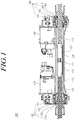
- FIG. 1 is a cross-sectional view of a steer-by-wire type power steering apparatus according to embodiments
- FIG. 2 is a cross-sectional view of a part of FIG. 1
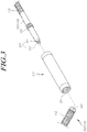
- FIG. 3 is an exploded perspective view of a part of FIG. 1
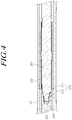
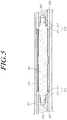
- FIGS. 4 and 5 are cross-sectional views of a part of a steer-by-wire type power steering apparatus according to embodiments
- FIG. 6 is an exploded perspective view of a part of a steer-by-wire type power steering apparatus according to embodiments
- FIG. 7 is a cross-sectional view of a steer-by-wire type power steering apparatus according to embodiments
- FIG. 8 is a cross-sectional view of a part of FIG. 7
- FIGS. 9 and 10 are exploded perspective views of a part of a steer-by-wire type power steering apparatus according to embodiments
- FIGS. 11 and 12 are cross-sectional views of a part of a steer-by-wire type power steering apparatus according to embodiments
- FIG. 13 is a block diagram for a part of a steer-by-wire type power steering apparatus according to embodiments
- FIG. 14 is a flow chart of a positioning method by a steer-by-wire type power steering apparatus according to embodiments
- FIG. 15 is a view for explaining a positioning method by a steer-by-wire type power steering apparatus according to embodiments
- FIG. 16 is a block diagram for a part of a steer-by-wire type power steering apparatus according to embodiments.
- a steer-by-wire type power steering apparatus 100 includes a housing 101 including an anti-rotation member 120; and a sliding bar 110 comprising an anti-rotation part 121 supported on the anti-rotation member 120 ans a screw 112 connected to a motor 130 and 140.
- the anti-rotation member 120 is a cylinder 120 having a first spline 111 formed on an inner circumferential surface therof, and the anti-rotation part 121 is a second spline 121 provided on an outer circumferenial surface of the sliding bar 110 and engaged with the first spline 111.
- the housing 101 is formed to be extend in the width direction of the vehicle.
- the housing 101 is hollow and includes the cylinder 120 and the sliding bar 110 therein.
- the opposite ends of the sliding bar 110 are connected with tie rods (not illustrated), respectively, and as the sliding bar 110 slides in the axial direction, the wheels (not illustrated) connected to the tie rods are steered.
- the sliding bar 110 includes screws 112 and 113 formed on the outer peripheral surface thereof. As will be described below, the torque of the motors 130 and 140 is transmitted to the sliding bar 110 by a first gear box 150 and a second gear box 160 that are coupled with the screw 112 and 113, respectively, and the sliding bar 110 is slid in the axial direction.
- the sliding bar 110 in order for the sliding bar 110 to be slid in the axial direction while receiving the torque of the motors 130 and 140, it is necessary to prevent the slide bar 110 from rotating around the central axis.
- the cylinder 120 prevents the sliding bar 110 from rotating while supporting the sliding bar 110 in the circumferential direction (see FIG. 2 ).
- the cylinder 120 is hollow and is provided inside the housing 101.
- the cylinder 120 can be press-fitted and fixed.
- the cylinder 120 includes a first spline 111 formed on the inner circumferential surface thereof.
- the sliding bar 110 includes a second spline 121 formed on the outer circumferential surface thereof.
- the sliding bar 110 is inserted into the cylinder 120 and the first spline 111 and the second spline 121 are engaged each other, so that the sliding bar 110 is supported in the cylinder 120 in the circumferential direction.
- the first spline 111 may be formed from one end to the other end in the axial direction of the cylinder 120, and the second spline 121 may be formed in the center of an anti-rotation bar 301 to be described later.
- first spline 111 and the second spline 121 are engaged with each other and the rotation of the sliding bar 110 is prevented, friction and noise may be reduced when the sliding bar 110 is slid in the axial direction, and the driver's steering feeling may be improved.
- the sliding bar 110 may be integrally manufactured. However, the sliding bar 110 may be divided into two or more parts in order to improve manufacturing convenience and assembly convenience, and may be provided inside the housing 101 in the assembled state, as illustrated in FIG. 3 .
- the sliding bar 110 is integrally formed, it is difficult to process the second spline 121 and the screws 112 and 113.
- the sliding bar 110 is divided into two or more parts, the second spline 121 and the screws 112 and 113 can be processed as separate parts, thereby improving the convenience of production.
- the screws 112 and 113 include a first screw 112 and a second screw 113, and the sliding bar 110 is connected to the first gear box 150 and the second gear box 160. If the sliding bar 110 is integrally formed, it is difficult to assemble the gear boxes in the state in which the sliding bar 110 is inserted into the housing 101. However, if the sliding bar 110 is divided into two or more parts, the parts can be inserted into the housing 101 in the state in which the gear boxes are assembled therewith, thereby improving assembling convenience.
- the sliding bar 110 may include an anti-rotation bar 301 including the second spline 121, and at least one screw bar 302 including the screws 112 and 113.
- the screw bar 302 may include any one of the first screw 112 and the second screw 113, and the anti-rotation bar 301 may include a second spline 121 and the remaining one of the first screw 112 and the second screw 113 (see FIG. 4 ).
- the anti-rotation bar 301 may include the second spline 121, and the screw bars 302 may include the first screw 112 and the second screw 113, respectively (see FIG. 5 ).
- the number of screw bars 302 is not necessarily limited to the above-described embodiments, and the sliding bar 110 may include a larger number of screw bars 302.
- anti-rotation bar 301 and the screw bar 302 are coupled to each other and to be slid in unison, and may be assembled inside the housing 101.
- one of the anti-rotation bar 301 and the screw bar 302 may include an engagement groove 320 that is recessed in the axial direction, and the other may include an engagement part 310 that is inserted into the engagement groove 320, so that the sliding bar 110 can be assembled by inserting the engagement part 310 into the engagement groove 320 in the housing 101.
- the drawing illustrates an embodiment in which the anti-rotation bar 301 includes the engagement part 310 and the screw bar 302 includes the engagement groove 320.
- the opposite case is also possible, and one end of the anti-rotation bar 301 may include the engagement part 310 and the other end may include the engagement groove 320.
- one end of the anti-rotation bar 301 may be coupled with the screw bar 302 via the engagement part 310 and the engagement groove 320.
- the opposite ends of the anti-rotation bar 301 may be respectively coupled to the screw bars 302 via the engagement parts 310 and the engagement grooves 320.
- the engagement part 310 may be screwed to the engagement groove 320, press-fitted to the engagement groove 320, or screwed to and press-fitted to the engagement groove 320.
- the engagement part 310 and the engagement groove 320 may respectively include threaded portions so as to be screwed together, or may be press-fitted together without including the threaded portions.
- the engagement part 310 may include a large-diameter portion 311 and a small-diameter portion 312 and the engagement groove 320 may be formed to correspond to the large-diameter portion 311 and the small-diameter portion 312.
- the drawing illustrating an embodiment in which the small-diameter portion 312 includes a threaded portion and the large-diameter portion 311 does not include a threaded portion.
- the small-diameter portion 312 is screwed to the engagement groove 320 and the large-diameter portion 311 is press-fitted to the engagement groove 320.
- the sliding bar 110 receives the torque of the motors 130 and 140 and slides in the axial direction.
- the screw-coupling may be loosened, and in the case in which the engagement part 310 is press-fitted to the engagement groove 320, a clearance may be generated by axial and radial movements and the degree of engagement may be reduced.
- the degree of engagement may be reduced.
- the screws 112 and 113 may include the first screw 112 and the second screw 113, and in this case, the motors 130 and 140 may include a first motor 130 connected to the first screw 112 by the first gear box 150 and a second motor 140 connected to the second screw 113 by the second gear box 160 (see FIG. 1 ).
- the sliding bar 110 may include a first screw 112 on one side in the axial direction and a second screw 113 on the other side in the axial direction.
- the sliding bar 110 is slid in the axial direction while receiving the torque of the first motor 130 and the second motor 140 via the first gear box 150 and the second gear box 160.
- the first gear box 150 includes a first motor pulley 151 coupled to the motor shaft of the first motor 130, a first ball nut 154 coupled to the first screw 112, a first nut pulley 153 coupled to the first motor pulley 154, and a first belt 152 connecting the first motor pulley 151 and the first nut pulley 153.
- the second gear box 160 includes a second motor pulley 161 coupled to the motor shaft of the second motor 140, a second ball nut 164 coupled to the second screw 113, a second nut pulley 163 coupled to the second motor pulley 164, and a second belt 162 connecting the second motor pulley 161 and the second nut pulley 163.
- the first motor 130 and the second motor 140 rotate the first ball nut 154 and the second ball nut 164 via the first belt 152 and the second belt 162, respectively, so that the torque is transmitted to the sliding bar 110, and the sliding bar 110 is slid in the axial direction while being prevented from rotating by the first and second splines 111 and 121.
- the screw direction of the first screw 112 and the screw direction of the second screw 113 may be the same as each other, or may be opposite each other, so that the durability and strength of the first spline 111 and the second spline 121 can be improved (see FIG. 1 ).
- the steer-by-wire type power steering apparatus 100 includes a sliding bar positioner 1300.
- the first motor 130 and the second motor 140 have different reduction ratios relative to the sliding bar 110, and the position of the sliding bar 110 may be determined by the sliding bar positioner 1300 based on the difference in rotation information due to the difference in the reduction ratio. A detailed description thereof will be made below.
- a steer-by-wire type power steering apparatus 600 includes a housing 101 including an anti-rotation member 610; and a sliding bar 110 comprising an anti-rotation part 711 supported on the anti-rotation member 610 ans a screw 112 connected to a motor 130 and 140.
- the housing 101 comprises a coupling hole 601 passing through an inner circumferential surface and an outer circumferential surface of the houing 101
- the anti-rotation member 610 is a coupling member 610 comprising a support portion 611 inserted into the coupling hole 601 ans protruding into the housing 101
- ans the anti-rotation part 711 is a slit groove 711, which is formed in an outer sircumferential surface of the sliding bar 110 to extend in an axial direction, and into which the support portion 611 is inserted
- the sliding bar 110 is connected to the tie rods at the opposite ends thereof such that wheels are steered as the sliding bar 110 is slid in the axial direction.
- the sliding bar 110 In order to ensure that the sliding bar 110 is slid in the axial direction while receiving the torques of the motors 130 and 140, the sliding bar 110 should be prevented from rotating around the central axis.
- the support portion 611 is inserted into the slit groove 711, and the sliding bar 110 is supported on a coupling member 610 in the circumferential direction (see FIG. 7 ).
- the housing 101 includes the coupling hole 601 passing through the outer and inner surfaces thereof, and the coupling member 610 is inserted into the coupling hole 601 and coupled to the housing 101.
- the coupling member 610 and the coupling hole 601 have threaded portions, so that that the coupling member 610 can be screwed to the housing 101.
- the sliding bar 110 includes a slit groove 711 extending in the axial direction on the outer circumferential surface of the housing 101 and the coupling member 610 includes the support portion 611 protruding into the inside of the housing 101.
- the support portion 611 is inserted into the slit groove 711, whereby the sliding bar 110 is slidable in the axial direction but is prevented from rotating about the center axis.
- Such a slit groove 711 may be formed to be longer in the axial direction than the movable range of the tie rod so as not to restrict the steering angle of wheels.
- the coupling member 610 comprises a first bush 612 coupled to the support portion 611 (see FIG. 9 ), the sliding bar 110 comprises a second bush 1001 supported on the inner surface of the slit groove 711 (see FIG. 10 ).
- the first bush 612 and the second bush 1001 may be made of a rubber material or an engineering plastic material such as POM (polyacetal), PA (polyamide), PC (polycarbonate), PI (polyimide), PBT (polybutylene terephthalate), so that shock and friction can be reduced, and thus the driver's steering sensitivity can be improved.
- POM polyacetal
- PA polyamide
- PC polycarbonate
- PI polyimide
- PBT polybutylene terephthalate
- the coupling member 610 may include the first bushing 612, and the sliding bar 110 may include the second bush 1001.
- the sliding bar 110 may include an anti-rotation bar 301 including the second spline 711, and one or more screw bars 302 including the screws 112 and 113.
- any one of the anti-rotation bar 301 and the screw bar 302 includes the engagement groove 320 and the other may include the engagement part 310.
- the feature in which the engagement groove 320 and the engagement part 310 are screwed to each other, press-fitted to each other, or screwed to and press-fitted to each other is the same as the embodiments described above, and thus a detailed description thereof will be omitted.
- the sliding bar 110 includes the first screw 112 and the second screw 113 to be connected to the first motor 130 and the second motor 140 via the first gear box 150 including the first pulley 151 or the like and the second gear box 160 including the second motor pulley 161 or the like is the same as the embodiments described above, and thus a detailed description thereof will be omitted.
- the screw direction of the first screw 112 and the screw direction of the second screw 113 may be the same as each other, or may be opposite each other, so that the durability and strength of the coupling member 610 and the slit groove 711 can be improved. Since the screw directions are opposite each other, the torques applied to the sliding bar 110 by the first motor 130 and the second motor 140 will cancel out each other.
- the steer-by-wire type power steering apparatus 600 includes a sliding bar positioner 1300.
- the first motor 130 and the second motor 140 have different reduction ratios relative to the sliding bar 110, and the position of the sliding bar 110 may be determined by the sliding bar positioner 1300 based on the difference in rotation information due to the difference in the reduction ratio.
- the steer-by-wire type power steering apparatus 100 or 600 may include a sliding bar positioner 1300 that determines the moving position of the sliding bar 110 based on first rotation information that is rotation information of the first motor 130 or the first gear box 150 and second rotation information that is rotation information of the second motor 140 or the second gear box 160.
- first motor 130 and the sliding bar 110 may have a first reduction ratio
- second motor 140 and the sliding bar 110 may have a second reduction ratio different from the first reduction ratio
- the rotating angle of the motor shaft of the first motor 130 and the rotating angle of the motor shaft of the second motor 140 have different values, so that the first rotation information and the second rotation information do not coincide with each other.
- the first reduction gear ratio and the second reduction gear ratio may be determined based on the first gear box 150, the second gear box 160, the first screw 112, the second screw 113, and the like.
- the first reduction gear ratio and the second reduction gear ratio may be determined based on the pitches, interval, inclinations, or the like of the first screw 112 and the second screw 113, or may be determined based on the diameters of the first motor pulley 151, the first nut pulley 153, or the like.
- the first and second rotation information are phase information, and the sliding bar positioner 1300 may determine the moving position of the sliding bar 110 based on the phase difference between the first rotation information and the second rotation information.
- the sliding bar positioner 1300 includes a rotation information receiver 1301 that receives first rotation information and second rotation information, a rotation information monitor 1302 that monitors changes in the first rotation information and the second rotation information, and a positioner 1303 that determines the moving position of the sliding bar 110 based on a monitoring result.
- the first rotation information and the second rotation information received by the rotation information receiver 1301 may be the rotation information of the first motor 130 and the rotation information of the second motor 140, respectively.
- the first rotation information and the second rotation information may be rotation information of each component of the first gear box 150 and rotation information of each component of the second gear box 160, respectively.
- the first rotation information may be the rotation information of the first motor pulley 151 or the rotation information of the first belt 152.
- the rotation information receiver 1301 may receive the first rotation information and the second rotation information from a sensor (not illustrated) that measures rotation information of a motor, a gear box, and the like.
- a motor position sensor (not illustrated) provided in each of the first motor 130 and the second motor 140 may receive the rotation information of the motor shaft.
- the motor position sensor may be driven in a low power mode. Since the vehicle battery is connected to a power source of the motor position sensor, the position sensor is capable of determining the position of the sliding bar 110 even when the ignition of the vehicle is turned off.
- the rotation information monitor 1302 monitors rotation information. Specifically, the rotation information monitor 1302 may monitor changes in the first rotation information and the second rotation information, a phase difference between the first rotation information and the second rotation information, and the like.
- the rotation information monitor 1302 may monitor an absolute angle change of each rotation information, and may monitor the number of times the phase difference between the first rotation information and the second rotation information becomes zero.
- the positioner 1303 may determine the moving position of the sliding bar 110. Specifically, the positioner 1303 may determine the position of the sliding bar 110 based on the result of monitoring by the rotation information monitor 1302.
- the positioner 1303 may determine the moving position of the sliding bar 110 using Equation 1.
- R K 360 ⁇ ⁇ + K ⁇ n
- R is the moving position of the sliding bar 110
- ⁇ is the phase difference between the first rotation information and the second rotation information
- K is the moving distance of the sliding bar 110 until the phase difference between the first rotation information and the second rotation information is changed from zero (0) and becomes the next zero (0) while the sliding bar 110 slides to one side
- n is the number of times the phase difference becomes zero while the sliding bar 110 slides to one side.
- Equation 1 the unit of deg is used for ⁇ , but when the unit of rad is used, 2n will be substituted for 360.
- the positioner 1303 may determine the position of the sliding bar 110 based on a preset reference value. For example, the positioner 1303 may determine the position of the sliding bar 110 in comparison with Table 1 based on the monitoring result of rotation information.
- Table 1 Stroke First Rotation Information Second Rotation Information 0 0 0 0.01 1.4 1.5 0.02 2.8 2.9 0.03 4.2 4.4 0.04 5.6 5.8 0.05 6.9 7.3 ... ... ... ... ... ... ... ...
- strokes corresponding to the positions of the sliding bar 110 are set in advance depending on the first rotation information and the second rotation information.
- the positioner 1303 may determine the position of the sliding bar 110 using Equation 2 and Equation 3.
- A first rotation information + 360 n ⁇ first reduction ratio
- B second rotation information + 360 m ⁇ second reduction ratio
- A is the position of the sliding bar 110 determined based on the first rotation information and the first reduction ratio
- B is the position of the sliding bar 110 determined based on the second rotation information and the second reduction ratio
- n and m are integers that respectively cause A and B not to exceed the maximum stroke of the sliding bar 110.
- Equation 2 and Equation 3 the first rotation information and the second rotation information are used in the unit of deg, and when used in the unit of rad, 2n will be put instead of 360.
- the position of the sliding bar 110 is an intersection of A and B.
- FIG. 14 is a flowchart of a sliding bar positioning method.
- step S1 rotation information is received.
- the sliding bar positioner 1300 may receive the first rotation information and the second rotation information from a sensor that detects the first rotation information and the second rotation information.
- step S2 rotation information is monitored.
- the sliding bar positioner 1300 may monitor absolute angles, relative angles, phase differences, and the like of the received first rotation information and second rotation information.
- step S3 the position of the sliding bar 100 is determined.
- the sliding bar positioner 1300 may determine the position of the sliding bar 110 based on the monitoring results of the first rotation information and the second rotation information.
- FIG. 15 is a view for explaining an example of determining the position of the sliding bar 110.
- FIG. 15 represents the phases of the first motor 130 and the second motor 140 and the stroke values of the sliding bar 110 according to the phases in a belt-type steering apparatus in which the first reduction ratio and the second reduction are determined by the lead widths of the first screw 112 and the second screw 113.
- FIG. 15 represents the results derived using the values in Table 2 below.
- Table 2 1 st screw lead 7 mm 2 st screw lead 6.7mm Belt reduction ratio 2.7 Stroke 156mm 1 st motor lock to lock 60.2 rev 2 nd motor lock to lock 62.9 rev Least common multiple of 1 st and 2 nd screw leads /(1 st screw lead) 67 Phase difference between 1st and 2nd motors 5.14 deg per rack stroke 0.1 mm 13.9 deg per rack stroke 0.1 mm 14.5 deg Rotating angle of 1 st motor Rotating angle of 2 nd motor
- FIG. 16 is a block diagram of the sliding bar positioner 1300 according to the present embodiments.
- a computer system 1600 such as the sliding bar positioner 1300 may include one or more elements selected from one or more processors 1610, memory 1610, a storage unit 1630, a user interface input unit 1640, and a user interface output unit 1650, which may communicate with each other through a bus 1660.
- the computer system 1600 may also include a network interface 1670 for connecting to a network.
- the processor 1610 may be a CPU or a semiconductor device that executes processing instructions stored in the memory 1620 and/or the storage unit 1630.
- the memory 1620 and the storage unit 1630 may include various types of volatile/nonvolatile storage mediums.
- the memory 1620 may include ROM 1624 and RAM 1625.
Landscapes
- Engineering & Computer Science (AREA)
- Chemical & Material Sciences (AREA)
- Combustion & Propulsion (AREA)
- Transportation (AREA)
- Mechanical Engineering (AREA)
- Power Steering Mechanism (AREA)
- Transmission Devices (AREA)
Applications Claiming Priority (2)
| Application Number | Priority Date | Filing Date | Title |
|---|---|---|---|
| KR1020180048057A KR102531433B1 (ko) | 2018-04-25 | 2018-04-25 | 다중 모터 기반의 조향 장치, 방법 및 시스템 |
| KR1020180105579A KR102106287B1 (ko) | 2018-09-04 | 2018-09-04 | 스티어 바이 와이어식 동력 보조 조향장치 |
Publications (3)
| Publication Number | Publication Date |
|---|---|
| EP3581465A2 true EP3581465A2 (fr) | 2019-12-18 |
| EP3581465A3 EP3581465A3 (fr) | 2020-04-15 |
| EP3581465B1 EP3581465B1 (fr) | 2023-10-11 |
Family
ID=66286191
Family Applications (1)
| Application Number | Title | Priority Date | Filing Date |
|---|---|---|---|
| EP19171046.6A Active EP3581465B1 (fr) | 2018-04-25 | 2019-04-25 | Appareil de direction assistée de type de direction par câbles |
Country Status (3)
| Country | Link |
|---|---|
| US (1) | US11939008B2 (fr) |
| EP (1) | EP3581465B1 (fr) |
| CN (1) | CN110395312B (fr) |
Cited By (4)
| Publication number | Priority date | Publication date | Assignee | Title |
|---|---|---|---|---|
| EP3699061A1 (fr) * | 2019-02-19 | 2020-08-26 | Jtekt Corporation | Dispositif de retournement |
| CN111688799A (zh) * | 2020-06-16 | 2020-09-22 | 中国电建集团装备研究院有限公司 | 一种基于行星滚柱丝杠副的车辆线控转向系统 |
| EP3733483A1 (fr) * | 2019-04-15 | 2020-11-04 | Jtekt Corporation | Dispositif de direction |
| US12552442B2 (en) | 2023-12-06 | 2026-02-17 | Schaeffler Technologies AG & Co. KG | Steering gear |
Families Citing this family (17)
| Publication number | Priority date | Publication date | Assignee | Title |
|---|---|---|---|---|
| JP7126877B2 (ja) * | 2018-06-22 | 2022-08-29 | 株式会社山田製作所 | ステアリング装置 |
| KR102898956B1 (ko) | 2019-11-06 | 2025-12-11 | 에이치엘만도 주식회사 | 스티어 바이 와이어식 조향장치 |
| KR102694031B1 (ko) * | 2020-02-12 | 2024-08-12 | 에이치엘만도 주식회사 | 스티어 바이 와이어식 조향장치 |
| KR102769271B1 (ko) * | 2020-06-18 | 2025-02-20 | 에이치엘만도 주식회사 | 스티어 바이 와이어식 조향장치 |
| US20210394818A1 (en) * | 2020-06-22 | 2021-12-23 | Schaeffler Technologies AG & Co. KG | Steering mechanism for autonomous vehicle |
| CN114104091B (zh) * | 2020-08-28 | 2023-05-05 | 华为技术有限公司 | 独立转向机构、转向系统及控制方法 |
| DE102020125258A1 (de) * | 2020-09-28 | 2022-03-31 | Knorr-Bremse Systeme für Nutzfahrzeuge GmbH | Lenksystem für ein Fahrzeug, insbesondere Nutzfahrzeug |
| CN116056969B (zh) * | 2021-02-24 | 2026-04-03 | 日本精工株式会社 | 转向装置的马达支承构造 |
| DE102021213063B4 (de) | 2021-11-22 | 2023-08-03 | Zf Friedrichshafen Ag | Lenkantrieb für eine Lenkachse eines lenkbaren Fahrzeugs, Lenkachse und Flurförderzeug |
| DE102021213067A1 (de) | 2021-11-22 | 2023-05-25 | Zf Friedrichshafen Ag | Lenkantrieb für eine Lenkachse eines lenkbaren Fahrzeugs, Lenkachse und Flurförderzeug |
| KR20230108006A (ko) * | 2022-01-10 | 2023-07-18 | 현대모비스 주식회사 | 차량용 조향 액추에이터 장치 |
| DE102022201939A1 (de) | 2022-02-24 | 2023-08-24 | Volkswagen Aktiengesellschaft | Verfahren zum Betreiben eines Kraftfahrzeugs, Assistenzsystem zum Steuern eines aktiven Lenksystems und Kraftfahrzeug |
| CN115402403B (zh) * | 2022-08-18 | 2023-10-13 | 合肥智行通智能科技有限公司 | 基于空心轴电机和转角传感器的线控转向装置及控制方法 |
| US20240067255A1 (en) * | 2022-08-31 | 2024-02-29 | Steering Solutions Ip Holding Corporation | Steer-by-wire road wheel actuator multi-groove ball screw anti-rotation mechanism |
| US20240140523A1 (en) * | 2022-08-31 | 2024-05-02 | Steering Solutions Ip Holding Corporation | Steer-by-wire road wheel actuator multi-groove ball screw anti-rotation mechanism |
| US12459557B2 (en) * | 2022-12-06 | 2025-11-04 | Zf Active Safety And Electronics Us Llc | Apparatus for use in turning steerable vehicle wheels |
| US20250050939A1 (en) * | 2023-08-10 | 2025-02-13 | Schaeffler Technologies AG & Co. KG | Steering mechanism for steer by wire vehicle |
Family Cites Families (31)
| Publication number | Priority date | Publication date | Assignee | Title |
|---|---|---|---|---|
| DE4138884A1 (de) | 1991-11-27 | 1993-06-03 | Zahnradfabrik Friedrichshafen | Einrichtung zum lenken der hinterraeder von fahrzeugen mit lenkbaren vorder- und hinterraedern |
| KR100543245B1 (ko) | 2003-03-17 | 2006-01-20 | 현대모비스 주식회사 | 전동식 조향휠의 절대위치 검출장치 |
| JP4221656B2 (ja) | 2003-04-09 | 2009-02-12 | 株式会社ジェイテクト | 車両用操舵装置 |
| DE102004061834A1 (de) | 2004-12-22 | 2006-07-06 | Bayerische Motoren Werke Ag | Lenkgetriebe mit Überlagerungslenkung |
| KR100599485B1 (ko) | 2004-06-09 | 2006-07-13 | 현대모비스 주식회사 | 스티어 바이 와이어 시스템의 랙바 위치 검출장치 |
| KR20060004279A (ko) | 2004-07-09 | 2006-01-12 | 현대모비스 주식회사 | 차량용 조향장치의 볼스크류바 회전 방지 구조 |
| KR20060032281A (ko) | 2004-10-12 | 2006-04-17 | 주식회사 만도 | 자동차 조향장치의 랙 바와 타이 로드의 조립부 구조 |
| US20080127762A1 (en) * | 2004-12-20 | 2008-06-05 | Bishop Innovation Limited | Composite Steering Rack |
| JP5311102B2 (ja) * | 2008-06-05 | 2013-10-09 | 株式会社ジェイテクト | 車両用操舵装置 |
| JP5213646B2 (ja) | 2008-11-04 | 2013-06-19 | カヤバ工業株式会社 | パワーステアリング装置 |
| KR101070315B1 (ko) | 2008-12-29 | 2011-10-06 | 한양대학교 산학협력단 | 좌우 독립형 전륜 조향장치 |
| DE102009038232A1 (de) | 2009-08-20 | 2011-02-24 | Schaeffler Technologies Gmbh & Co. Kg | Servolenkung |
| JP5506529B2 (ja) * | 2010-05-13 | 2014-05-28 | Ntn株式会社 | ステアバイワイヤ式操舵装置 |
| JP5547563B2 (ja) | 2010-06-25 | 2014-07-16 | Ntn株式会社 | 電動アクチュエータ |
| JP2012045978A (ja) | 2010-08-24 | 2012-03-08 | Jtekt Corp | 車両用操舵装置 |
| JP2013086586A (ja) | 2011-10-14 | 2013-05-13 | Jtekt Corp | 電動パワーステアリング装置 |
| KR101454505B1 (ko) | 2011-11-17 | 2014-10-28 | 주식회사 만도 | 랙구동형 동력 보조 조향장치 |
| KR101450325B1 (ko) | 2012-02-24 | 2014-10-22 | 주식회사 만도 | 랙구동형 동력 보조 조향장치 |
| US8890461B2 (en) * | 2012-03-22 | 2014-11-18 | Bose Corporation | Actuator assembly with preloaded ball screws |
| KR20150008550A (ko) | 2013-07-15 | 2015-01-23 | 현대모비스 주식회사 | 리어 휠 스티어링 장치의 리드스크류 회전 방지 구조 |
| JP6433142B2 (ja) | 2014-04-16 | 2018-12-05 | Ntn株式会社 | 後輪転舵装置 |
| DE102014216462A1 (de) | 2014-08-19 | 2016-02-25 | Bayerische Motoren Werke Aktiengesellschaft | Lenksystem eines zweispurigen Fahrzeugs |
| JP6295483B2 (ja) | 2014-09-19 | 2018-03-20 | 日立オートモティブシステムズ株式会社 | パワーステアリング装置およびパワーステアリング装置の組み立て方法 |
| KR20160111065A (ko) | 2015-03-16 | 2016-09-26 | 주식회사 만도 | 전동식 동력 보조 조향장치 |
| DE102016209161B4 (de) | 2016-05-25 | 2019-08-01 | Zf Friedrichshafen Ag | Stelleinrichtung und Verwendung der Stelleinrichtung |
| KR102422336B1 (ko) | 2016-06-22 | 2022-07-19 | 현대모비스 주식회사 | 후륜조향장치 |
| JP6873376B2 (ja) | 2017-01-25 | 2021-05-19 | 日立Astemo株式会社 | シャフトの回り止め機構及び伸縮アクチュエータ |
| KR20190001964A (ko) | 2017-06-28 | 2019-01-08 | 현대자동차주식회사 | 차량용 조향 장치 및 그 제어 방법 |
| JP7331449B2 (ja) * | 2019-05-15 | 2023-08-23 | 株式会社ジェイテクト | ステアリング装置 |
| EP3782875B1 (fr) * | 2019-08-22 | 2022-07-20 | Jtekt Corporation | Dispositif de direction et procédé de détection d'anomalie dans un dispositif de direction |
| EP3792149B1 (fr) * | 2019-08-22 | 2023-09-27 | Jtekt Corporation | Dispositif et procédé de direction |
-
2019
- 2019-04-21 US US16/389,950 patent/US11939008B2/en active Active
- 2019-04-25 EP EP19171046.6A patent/EP3581465B1/fr active Active
- 2019-04-25 CN CN201910338281.4A patent/CN110395312B/zh active Active
Non-Patent Citations (1)
| Title |
|---|
| None |
Cited By (5)
| Publication number | Priority date | Publication date | Assignee | Title |
|---|---|---|---|---|
| EP3699061A1 (fr) * | 2019-02-19 | 2020-08-26 | Jtekt Corporation | Dispositif de retournement |
| US11554807B2 (en) | 2019-02-19 | 2023-01-17 | Jtekt Corporation | Turning device |
| EP3733483A1 (fr) * | 2019-04-15 | 2020-11-04 | Jtekt Corporation | Dispositif de direction |
| CN111688799A (zh) * | 2020-06-16 | 2020-09-22 | 中国电建集团装备研究院有限公司 | 一种基于行星滚柱丝杠副的车辆线控转向系统 |
| US12552442B2 (en) | 2023-12-06 | 2026-02-17 | Schaeffler Technologies AG & Co. KG | Steering gear |
Also Published As
| Publication number | Publication date |
|---|---|
| EP3581465B1 (fr) | 2023-10-11 |
| EP3581465A3 (fr) | 2020-04-15 |
| US11939008B2 (en) | 2024-03-26 |
| CN110395312A (zh) | 2019-11-01 |
| US20190329816A1 (en) | 2019-10-31 |
| CN110395312B (zh) | 2023-08-08 |
Similar Documents
| Publication | Publication Date | Title |
|---|---|---|
| EP3581465B1 (fr) | Appareil de direction assistée de type de direction par câbles | |
| US11897549B2 (en) | Steer-by-wire type steering apparatus | |
| US20020108803A1 (en) | Electric power steering apparatus | |
| CN114423668B (zh) | 线控转向式转向装置 | |
| US10046794B2 (en) | Rack assist type electric power steering apparatus | |
| CN115135563B (zh) | 线控转向式转向装置 | |
| CN108284870B (zh) | 用于车辆的转向柱 | |
| US20170057539A1 (en) | Steering column for vehicle | |
| CN107428363B (zh) | 一件式的输入轴 | |
| US8554413B2 (en) | Steering control apparatus | |
| EP2657105A1 (fr) | Direction électrique | |
| US11767052B2 (en) | Steering device of vehicle | |
| CN115703500A (zh) | 线控转向式转向装置 | |
| US12005971B2 (en) | Rack assist type power steering apparatus | |
| US20180086364A1 (en) | Steering column for vehicle | |
| WO2017086013A1 (fr) | Dispositif de direction assistée et dispositif de direction le comprenant | |
| EP1304504B1 (fr) | Dispositif de modification de vitesse à vis sans fin et direction assistée électrique | |
| JPH10305778A (ja) | パワーステアリング装置 | |
| KR102508009B1 (ko) | 자동차의 조향컬럼 | |
| EP1944217B1 (fr) | Appareil de boîtier de direction à crémaillère à entraînement central | |
| US20240383521A1 (en) | Steer-by-wire steering device | |
| JP2002053053A (ja) | パワーステアリング装置 | |
| JP2007216721A (ja) | 電動パワーステアリング装置 | |
| JP2002053054A (ja) | パワーステアリング装置 | |
| CN113544043A (zh) | 齿条驱动电动动力辅助转向装置 |
Legal Events
| Date | Code | Title | Description |
|---|---|---|---|
| PUAI | Public reference made under article 153(3) epc to a published international application that has entered the european phase |
Free format text: ORIGINAL CODE: 0009012 |
|
| STAA | Information on the status of an ep patent application or granted ep patent |
Free format text: STATUS: THE APPLICATION HAS BEEN PUBLISHED |
|
| AK | Designated contracting states |
Kind code of ref document: A2 Designated state(s): AL AT BE BG CH CY CZ DE DK EE ES FI FR GB GR HR HU IE IS IT LI LT LU LV MC MK MT NL NO PL PT RO RS SE SI SK SM TR |
|
| AX | Request for extension of the european patent |
Extension state: BA ME |
|
| PUAL | Search report despatched |
Free format text: ORIGINAL CODE: 0009013 |
|
| AK | Designated contracting states |
Kind code of ref document: A3 Designated state(s): AL AT BE BG CH CY CZ DE DK EE ES FI FR GB GR HR HU IE IS IT LI LT LU LV MC MK MT NL NO PL PT RO RS SE SI SK SM TR |
|
| AX | Request for extension of the european patent |
Extension state: BA ME |
|
| RIC1 | Information provided on ipc code assigned before grant |
Ipc: B62D 3/02 20060101ALI20200310BHEP Ipc: B62D 5/04 20060101ALI20200310BHEP Ipc: B62D 3/12 20060101AFI20200310BHEP |
|
| STAA | Information on the status of an ep patent application or granted ep patent |
Free format text: STATUS: REQUEST FOR EXAMINATION WAS MADE |
|
| 17P | Request for examination filed |
Effective date: 20201014 |
|
| RBV | Designated contracting states (corrected) |
Designated state(s): AL AT BE BG CH CY CZ DE DK EE ES FI FR GB GR HR HU IE IS IT LI LT LU LV MC MK MT NL NO PL PT RO RS SE SI SK SM TR |
|
| STAA | Information on the status of an ep patent application or granted ep patent |
Free format text: STATUS: EXAMINATION IS IN PROGRESS |
|
| 17Q | First examination report despatched |
Effective date: 20210311 |
|
| RAP3 | Party data changed (applicant data changed or rights of an application transferred) |
Owner name: HL MANDO CORPORATION |
|
| GRAP | Despatch of communication of intention to grant a patent |
Free format text: ORIGINAL CODE: EPIDOSNIGR1 |
|
| STAA | Information on the status of an ep patent application or granted ep patent |
Free format text: STATUS: GRANT OF PATENT IS INTENDED |
|
| INTG | Intention to grant announced |
Effective date: 20230425 |
|
| GRAS | Grant fee paid |
Free format text: ORIGINAL CODE: EPIDOSNIGR3 |
|
| GRAA | (expected) grant |
Free format text: ORIGINAL CODE: 0009210 |
|
| STAA | Information on the status of an ep patent application or granted ep patent |
Free format text: STATUS: THE PATENT HAS BEEN GRANTED |
|
| P01 | Opt-out of the competence of the unified patent court (upc) registered |
Effective date: 20230816 |
|
| AK | Designated contracting states |
Kind code of ref document: B1 Designated state(s): AL AT BE BG CH CY CZ DE DK EE ES FI FR GB GR HR HU IE IS IT LI LT LU LV MC MK MT NL NO PL PT RO RS SE SI SK SM TR |
|
| REG | Reference to a national code |
Ref country code: GB Ref legal event code: FG4D |
|
| REG | Reference to a national code |
Ref country code: CH Ref legal event code: EP |
|
| REG | Reference to a national code |
Ref country code: DE Ref legal event code: R096 Ref document number: 602019038994 Country of ref document: DE |
|
| REG | Reference to a national code |
Ref country code: IE Ref legal event code: FG4D |
|
| REG | Reference to a national code |
Ref country code: LT Ref legal event code: MG9D |
|
| REG | Reference to a national code |
Ref country code: NL Ref legal event code: MP Effective date: 20231011 |
|
| REG | Reference to a national code |
Ref country code: AT Ref legal event code: MK05 Ref document number: 1619961 Country of ref document: AT Kind code of ref document: T Effective date: 20231011 |
|
| PG25 | Lapsed in a contracting state [announced via postgrant information from national office to epo] |
Ref country code: NL Free format text: LAPSE BECAUSE OF FAILURE TO SUBMIT A TRANSLATION OF THE DESCRIPTION OR TO PAY THE FEE WITHIN THE PRESCRIBED TIME-LIMIT Effective date: 20231011 |
|
| PG25 | Lapsed in a contracting state [announced via postgrant information from national office to epo] |
Ref country code: GR Free format text: LAPSE BECAUSE OF FAILURE TO SUBMIT A TRANSLATION OF THE DESCRIPTION OR TO PAY THE FEE WITHIN THE PRESCRIBED TIME-LIMIT Effective date: 20240112 |
|
| PG25 | Lapsed in a contracting state [announced via postgrant information from national office to epo] |
Ref country code: IS Free format text: LAPSE BECAUSE OF FAILURE TO SUBMIT A TRANSLATION OF THE DESCRIPTION OR TO PAY THE FEE WITHIN THE PRESCRIBED TIME-LIMIT Effective date: 20240211 |
|
| PG25 | Lapsed in a contracting state [announced via postgrant information from national office to epo] |
Ref country code: LT Free format text: LAPSE BECAUSE OF FAILURE TO SUBMIT A TRANSLATION OF THE DESCRIPTION OR TO PAY THE FEE WITHIN THE PRESCRIBED TIME-LIMIT Effective date: 20231011 |
|
| PG25 | Lapsed in a contracting state [announced via postgrant information from national office to epo] |
Ref country code: AT Free format text: LAPSE BECAUSE OF FAILURE TO SUBMIT A TRANSLATION OF THE DESCRIPTION OR TO PAY THE FEE WITHIN THE PRESCRIBED TIME-LIMIT Effective date: 20231011 |
|
| PG25 | Lapsed in a contracting state [announced via postgrant information from national office to epo] |
Ref country code: ES Free format text: LAPSE BECAUSE OF FAILURE TO SUBMIT A TRANSLATION OF THE DESCRIPTION OR TO PAY THE FEE WITHIN THE PRESCRIBED TIME-LIMIT Effective date: 20231011 |
|
| PG25 | Lapsed in a contracting state [announced via postgrant information from national office to epo] |
Ref country code: LT Free format text: LAPSE BECAUSE OF FAILURE TO SUBMIT A TRANSLATION OF THE DESCRIPTION OR TO PAY THE FEE WITHIN THE PRESCRIBED TIME-LIMIT Effective date: 20231011 Ref country code: IS Free format text: LAPSE BECAUSE OF FAILURE TO SUBMIT A TRANSLATION OF THE DESCRIPTION OR TO PAY THE FEE WITHIN THE PRESCRIBED TIME-LIMIT Effective date: 20240211 Ref country code: GR Free format text: LAPSE BECAUSE OF FAILURE TO SUBMIT A TRANSLATION OF THE DESCRIPTION OR TO PAY THE FEE WITHIN THE PRESCRIBED TIME-LIMIT Effective date: 20240112 Ref country code: ES Free format text: LAPSE BECAUSE OF FAILURE TO SUBMIT A TRANSLATION OF THE DESCRIPTION OR TO PAY THE FEE WITHIN THE PRESCRIBED TIME-LIMIT Effective date: 20231011 Ref country code: BG Free format text: LAPSE BECAUSE OF FAILURE TO SUBMIT A TRANSLATION OF THE DESCRIPTION OR TO PAY THE FEE WITHIN THE PRESCRIBED TIME-LIMIT Effective date: 20240111 Ref country code: AT Free format text: LAPSE BECAUSE OF FAILURE TO SUBMIT A TRANSLATION OF THE DESCRIPTION OR TO PAY THE FEE WITHIN THE PRESCRIBED TIME-LIMIT Effective date: 20231011 Ref country code: PT Free format text: LAPSE BECAUSE OF FAILURE TO SUBMIT A TRANSLATION OF THE DESCRIPTION OR TO PAY THE FEE WITHIN THE PRESCRIBED TIME-LIMIT Effective date: 20240212 |
|
| PG25 | Lapsed in a contracting state [announced via postgrant information from national office to epo] |
Ref country code: SE Free format text: LAPSE BECAUSE OF FAILURE TO SUBMIT A TRANSLATION OF THE DESCRIPTION OR TO PAY THE FEE WITHIN THE PRESCRIBED TIME-LIMIT Effective date: 20231011 Ref country code: RS Free format text: LAPSE BECAUSE OF FAILURE TO SUBMIT A TRANSLATION OF THE DESCRIPTION OR TO PAY THE FEE WITHIN THE PRESCRIBED TIME-LIMIT Effective date: 20231011 Ref country code: PL Free format text: LAPSE BECAUSE OF FAILURE TO SUBMIT A TRANSLATION OF THE DESCRIPTION OR TO PAY THE FEE WITHIN THE PRESCRIBED TIME-LIMIT Effective date: 20231011 Ref country code: NO Free format text: LAPSE BECAUSE OF FAILURE TO SUBMIT A TRANSLATION OF THE DESCRIPTION OR TO PAY THE FEE WITHIN THE PRESCRIBED TIME-LIMIT Effective date: 20240111 Ref country code: LV Free format text: LAPSE BECAUSE OF FAILURE TO SUBMIT A TRANSLATION OF THE DESCRIPTION OR TO PAY THE FEE WITHIN THE PRESCRIBED TIME-LIMIT Effective date: 20231011 Ref country code: HR Free format text: LAPSE BECAUSE OF FAILURE TO SUBMIT A TRANSLATION OF THE DESCRIPTION OR TO PAY THE FEE WITHIN THE PRESCRIBED TIME-LIMIT Effective date: 20231011 |
|
| PG25 | Lapsed in a contracting state [announced via postgrant information from national office to epo] |
Ref country code: DK Free format text: LAPSE BECAUSE OF FAILURE TO SUBMIT A TRANSLATION OF THE DESCRIPTION OR TO PAY THE FEE WITHIN THE PRESCRIBED TIME-LIMIT Effective date: 20231011 |
|
| REG | Reference to a national code |
Ref country code: DE Ref legal event code: R097 Ref document number: 602019038994 Country of ref document: DE |
|
| PG25 | Lapsed in a contracting state [announced via postgrant information from national office to epo] |
Ref country code: CZ Free format text: LAPSE BECAUSE OF FAILURE TO SUBMIT A TRANSLATION OF THE DESCRIPTION OR TO PAY THE FEE WITHIN THE PRESCRIBED TIME-LIMIT Effective date: 20231011 |
|
| PG25 | Lapsed in a contracting state [announced via postgrant information from national office to epo] |
Ref country code: SK Free format text: LAPSE BECAUSE OF FAILURE TO SUBMIT A TRANSLATION OF THE DESCRIPTION OR TO PAY THE FEE WITHIN THE PRESCRIBED TIME-LIMIT Effective date: 20231011 |
|
| PG25 | Lapsed in a contracting state [announced via postgrant information from national office to epo] |
Ref country code: SM Free format text: LAPSE BECAUSE OF FAILURE TO SUBMIT A TRANSLATION OF THE DESCRIPTION OR TO PAY THE FEE WITHIN THE PRESCRIBED TIME-LIMIT Effective date: 20231011 Ref country code: SK Free format text: LAPSE BECAUSE OF FAILURE TO SUBMIT A TRANSLATION OF THE DESCRIPTION OR TO PAY THE FEE WITHIN THE PRESCRIBED TIME-LIMIT Effective date: 20231011 Ref country code: RO Free format text: LAPSE BECAUSE OF FAILURE TO SUBMIT A TRANSLATION OF THE DESCRIPTION OR TO PAY THE FEE WITHIN THE PRESCRIBED TIME-LIMIT Effective date: 20231011 Ref country code: IT Free format text: LAPSE BECAUSE OF FAILURE TO SUBMIT A TRANSLATION OF THE DESCRIPTION OR TO PAY THE FEE WITHIN THE PRESCRIBED TIME-LIMIT Effective date: 20231011 Ref country code: EE Free format text: LAPSE BECAUSE OF FAILURE TO SUBMIT A TRANSLATION OF THE DESCRIPTION OR TO PAY THE FEE WITHIN THE PRESCRIBED TIME-LIMIT Effective date: 20231011 Ref country code: DK Free format text: LAPSE BECAUSE OF FAILURE TO SUBMIT A TRANSLATION OF THE DESCRIPTION OR TO PAY THE FEE WITHIN THE PRESCRIBED TIME-LIMIT Effective date: 20231011 Ref country code: CZ Free format text: LAPSE BECAUSE OF FAILURE TO SUBMIT A TRANSLATION OF THE DESCRIPTION OR TO PAY THE FEE WITHIN THE PRESCRIBED TIME-LIMIT Effective date: 20231011 |
|
| PLBE | No opposition filed within time limit |
Free format text: ORIGINAL CODE: 0009261 |
|
| STAA | Information on the status of an ep patent application or granted ep patent |
Free format text: STATUS: NO OPPOSITION FILED WITHIN TIME LIMIT |
|
| 26N | No opposition filed |
Effective date: 20240712 |
|
| PG25 | Lapsed in a contracting state [announced via postgrant information from national office to epo] |
Ref country code: SI Free format text: LAPSE BECAUSE OF FAILURE TO SUBMIT A TRANSLATION OF THE DESCRIPTION OR TO PAY THE FEE WITHIN THE PRESCRIBED TIME-LIMIT Effective date: 20231011 |
|
| PG25 | Lapsed in a contracting state [announced via postgrant information from national office to epo] |
Ref country code: SI Free format text: LAPSE BECAUSE OF FAILURE TO SUBMIT A TRANSLATION OF THE DESCRIPTION OR TO PAY THE FEE WITHIN THE PRESCRIBED TIME-LIMIT Effective date: 20231011 |
|
| PG25 | Lapsed in a contracting state [announced via postgrant information from national office to epo] |
Ref country code: MC Free format text: LAPSE BECAUSE OF FAILURE TO SUBMIT A TRANSLATION OF THE DESCRIPTION OR TO PAY THE FEE WITHIN THE PRESCRIBED TIME-LIMIT Effective date: 20231011 |
|
| PG25 | Lapsed in a contracting state [announced via postgrant information from national office to epo] |
Ref country code: MC Free format text: LAPSE BECAUSE OF FAILURE TO SUBMIT A TRANSLATION OF THE DESCRIPTION OR TO PAY THE FEE WITHIN THE PRESCRIBED TIME-LIMIT Effective date: 20231011 |
|
| REG | Reference to a national code |
Ref country code: CH Ref legal event code: PL |
|
| PG25 | Lapsed in a contracting state [announced via postgrant information from national office to epo] |
Ref country code: LU Free format text: LAPSE BECAUSE OF NON-PAYMENT OF DUE FEES Effective date: 20240425 |
|
| GBPC | Gb: european patent ceased through non-payment of renewal fee |
Effective date: 20240425 |
|
| REG | Reference to a national code |
Ref country code: BE Ref legal event code: MM Effective date: 20240430 |
|
| PG25 | Lapsed in a contracting state [announced via postgrant information from national office to epo] |
Ref country code: LU Free format text: LAPSE BECAUSE OF NON-PAYMENT OF DUE FEES Effective date: 20240425 |
|
| PG25 | Lapsed in a contracting state [announced via postgrant information from national office to epo] |
Ref country code: BE Free format text: LAPSE BECAUSE OF NON-PAYMENT OF DUE FEES Effective date: 20240430 |
|
| PG25 | Lapsed in a contracting state [announced via postgrant information from national office to epo] |
Ref country code: GB Free format text: LAPSE BECAUSE OF NON-PAYMENT OF DUE FEES Effective date: 20240425 |
|
| PG25 | Lapsed in a contracting state [announced via postgrant information from national office to epo] |
Ref country code: FR Free format text: LAPSE BECAUSE OF NON-PAYMENT OF DUE FEES Effective date: 20240430 |
|
| PG25 | Lapsed in a contracting state [announced via postgrant information from national office to epo] |
Ref country code: GB Free format text: LAPSE BECAUSE OF NON-PAYMENT OF DUE FEES Effective date: 20240425 Ref country code: FR Free format text: LAPSE BECAUSE OF NON-PAYMENT OF DUE FEES Effective date: 20240430 Ref country code: BE Free format text: LAPSE BECAUSE OF NON-PAYMENT OF DUE FEES Effective date: 20240430 Ref country code: CH Free format text: LAPSE BECAUSE OF NON-PAYMENT OF DUE FEES Effective date: 20240430 |
|
| PG25 | Lapsed in a contracting state [announced via postgrant information from national office to epo] |
Ref country code: IE Free format text: LAPSE BECAUSE OF NON-PAYMENT OF DUE FEES Effective date: 20240425 |
|
| PGFP | Annual fee paid to national office [announced via postgrant information from national office to epo] |
Ref country code: DE Payment date: 20250220 Year of fee payment: 7 |
|
| PG25 | Lapsed in a contracting state [announced via postgrant information from national office to epo] |
Ref country code: CY Free format text: LAPSE BECAUSE OF FAILURE TO SUBMIT A TRANSLATION OF THE DESCRIPTION OR TO PAY THE FEE WITHIN THE PRESCRIBED TIME-LIMIT; INVALID AB INITIO Effective date: 20190425 |
|
| PG25 | Lapsed in a contracting state [announced via postgrant information from national office to epo] |
Ref country code: HU Free format text: LAPSE BECAUSE OF FAILURE TO SUBMIT A TRANSLATION OF THE DESCRIPTION OR TO PAY THE FEE WITHIN THE PRESCRIBED TIME-LIMIT; INVALID AB INITIO Effective date: 20190425 |
|
| PG25 | Lapsed in a contracting state [announced via postgrant information from national office to epo] |
Ref country code: FI Free format text: LAPSE BECAUSE OF FAILURE TO SUBMIT A TRANSLATION OF THE DESCRIPTION OR TO PAY THE FEE WITHIN THE PRESCRIBED TIME-LIMIT Effective date: 20231011 |