EP3583661B1 - Kompaktes duales zirkulares polarisations-mehrbandwellenleiter-speisenetzwerk - Google Patents
Kompaktes duales zirkulares polarisations-mehrbandwellenleiter-speisenetzwerk Download PDFInfo
- Publication number
- EP3583661B1 EP3583661B1 EP18754081.0A EP18754081A EP3583661B1 EP 3583661 B1 EP3583661 B1 EP 3583661B1 EP 18754081 A EP18754081 A EP 18754081A EP 3583661 B1 EP3583661 B1 EP 3583661B1
- Authority
- EP
- European Patent Office
- Prior art keywords
- waveguide
- branch
- coupled
- reject filter
- polarized signal
- Prior art date
- Legal status (The legal status is an assumption and is not a legal conclusion. Google has not performed a legal analysis and makes no representation as to the accuracy of the status listed.)
- Active
Links
Images


Classifications
-
- H—ELECTRICITY
- H01—ELECTRIC ELEMENTS
- H01P—WAVEGUIDES; RESONATORS, LINES, OR OTHER DEVICES OF THE WAVEGUIDE TYPE
- H01P1/00—Auxiliary devices
- H01P1/20—Frequency-selective devices, e.g. filters
- H01P1/213—Frequency-selective devices, e.g. filters combining or separating two or more different frequencies
- H01P1/2138—Frequency-selective devices, e.g. filters combining or separating two or more different frequencies using hollow waveguide filters
-
- H—ELECTRICITY
- H01—ELECTRIC ELEMENTS
- H01Q—ANTENNAS, i.e. RADIO AERIALS
- H01Q15/00—Devices for reflection, refraction, diffraction or polarisation of waves radiated from an antenna, e.g. quasi-optical devices
- H01Q15/24—Polarising devices; Polarisation filters
- H01Q15/242—Polarisation converters
- H01Q15/244—Polarisation converters converting a linear polarised wave into a circular polarised wave
-
- H—ELECTRICITY
- H01—ELECTRIC ELEMENTS
- H01P—WAVEGUIDES; RESONATORS, LINES, OR OTHER DEVICES OF THE WAVEGUIDE TYPE
- H01P1/00—Auxiliary devices
- H01P1/165—Auxiliary devices for rotating the plane of polarisation
- H01P1/17—Auxiliary devices for rotating the plane of polarisation for producing a continuously rotating polarisation, e.g. circular polarisation
- H01P1/171—Auxiliary devices for rotating the plane of polarisation for producing a continuously rotating polarisation, e.g. circular polarisation using a corrugated or ridged waveguide section
-
- H—ELECTRICITY
- H01—ELECTRIC ELEMENTS
- H01P—WAVEGUIDES; RESONATORS, LINES, OR OTHER DEVICES OF THE WAVEGUIDE TYPE
- H01P1/00—Auxiliary devices
- H01P1/20—Frequency-selective devices, e.g. filters
- H01P1/207—Hollow waveguide filters
- H01P1/209—Hollow waveguide filters comprising one or more branching arms or cavities wholly outside the main waveguide
-
- H—ELECTRICITY
- H01—ELECTRIC ELEMENTS
- H01P—WAVEGUIDES; RESONATORS, LINES, OR OTHER DEVICES OF THE WAVEGUIDE TYPE
- H01P5/00—Coupling devices of the waveguide type
- H01P5/12—Coupling devices having more than two ports
- H01P5/16—Conjugate devices, i.e. devices having at least one port decoupled from one other port
-
- H—ELECTRICITY
- H01—ELECTRIC ELEMENTS
- H01Q—ANTENNAS, i.e. RADIO AERIALS
- H01Q13/00—Waveguide horns or mouths; Slot antennas; Leaky-waveguide antennas; Equivalent structures causing radiation along the transmission path of a guided wave
- H01Q13/02—Waveguide horns
- H01Q13/0241—Waveguide horns radiating a circularly polarised wave
-
- H—ELECTRICITY
- H01—ELECTRIC ELEMENTS
- H01Q—ANTENNAS, i.e. RADIO AERIALS
- H01Q13/00—Waveguide horns or mouths; Slot antennas; Leaky-waveguide antennas; Equivalent structures causing radiation along the transmission path of a guided wave
- H01Q13/02—Waveguide horns
- H01Q13/025—Multimode horn antennas; Horns using higher mode of propagation
- H01Q13/0258—Orthomode horns
-
- H—ELECTRICITY
- H01—ELECTRIC ELEMENTS
- H01Q—ANTENNAS, i.e. RADIO AERIALS
- H01Q15/00—Devices for reflection, refraction, diffraction or polarisation of waves radiated from an antenna, e.g. quasi-optical devices
- H01Q15/02—Refracting or diffracting devices, e.g. lens, prism
- H01Q15/12—Refracting or diffracting devices, e.g. lens, prism functioning also as polarisation filter
Definitions
- the present invention generally relates to waveguides and more particularly to waveguide feed networks.
- Waveguide feed networks that can transmit left hand and right hand circularly polarized signals through circular waveguides and also can receive left hand and right hand circularly polarized signals from circular waveguides may require two transmit ports and two receive ports with good isolation between the ports.
- the waveguide feed networks may require filtering to provide the required isolation between the ports.
- Transmitter circuits may be coupled to transmit ports and receiver circuits may be coupled to the receive ports for transmitting and receiving the signals.
- the waveguide feed network may be coupled to circular waveguides to implement a transformation from a linearly polarized signal at a transmit port to one of the left hand circularly polarized signal or right hand circularly polarized signal at the circular waveguide.
- the waveguide feed network may implement a transformation from one of the left hand circularly polarized signal or right hand circularly polarized signal at the circular waveguide to a linearly polarized signal at a receive port. This can make the design of an integrated waveguide feed network for transmitting and receiving signals with both left hand circular polarization and right hand circular polarization very complex.
- Document 2 202 839 B1 relates to an assembly having an asymmetric diplexing orthomode transducer comprising two branches coupled to a main waveguide by two parallel coupling slots.
- the branches are respectively linked to two waveguides of an unbalanced branched coupler.
- the slots are formed in two orthogonal walls of the waveguide, and linked to the coupler via stub filters and recombination circuits.
- the coupler has two different splitting coefficients that are optimized to compensate for orthogonal spurious components of electric field produced by the asymmetry of the transducer.
- An independent claim is also included for a method for developing a compact excitation assembly for generating a circular polarization in an antenna.
- Document 3 056 096 A relates in general to microwave multiplexers and to improved high frequency multiplexer apparatus which allows the use of a single antenna and/or transmission line for simultaneous transmission and reception of signals within a plurality of frequency bands.
- Document D3 9,297,893 B2 describes an antenna system including: an input port configured to receive tracking mode signals, in two orthogonal polarizations, from a target; a tracking coupler, configured to receive the tracking mode signals from the input port, the tracking coupler including: a first pair of opposed slot couplers configured to extract tracking signals from the tracking mode signals in a first one of the orthogonal polarizations, and a second pair of opposed slot couplers configured to extract tracking signals from the tracking mode signals in a second one of the orthogonal polarizations; and a tracking combiner network configured to combine the extracted tracking signals from the pairs of opposed slot couplers to generate tracking output signals for use in controlling the antenna system to track the target.
- Document US 2014/022138 A1 relates to transmitting and receiving antenna comprises an array of feeds clustered by groups of four adjacent feeds along two directions X, Y of a plane, each feed comprising two transmitting ports and two receiving ports with orthogonal polarizations.
- the first, or the second, transmitting ports, respectively the first, or the second, receiving ports, corresponding to a same pair of frequency and polarization values are connected two-by-two in the direction X then two-by-two in the direction Y, the four interconnected transmitting ports forming a transmitting beam and the four interconnected receiving ports forming a receiving beam.
- the present invention relates to a feed network, a receiver unit and a method of operating a transmitter unit.
- the present invention is defined by the set of appended claims. In the following, parts of the description and drawing referring to examples, which are not covered by the claims are not presented as embodiments of the invention, but as illustrative examples useful for understanding the invention.
- a transmitter unit of a feed network for transmitting circularly polarized signals is described according to claim 1.
- a receiver unit of a feed network for receiving circularly polarized signals is described according to claim 10.
- a method of operating a transmitter unit of a feed network for transmitting circularly polarized signals is described according to claim 15.
- a satellite may include a satellite receiver coupled to a satellite antenna system for receiving uplink signals, and may also include a satellite transmitter coupled to the satellite antenna system for transmitting downlink signals.
- the feed network may be coupled between elements of the satellite antenna system and the satellite receiver and also may be couple between the elements of the satellite antenna system and the satellite transmitter.
- the feed network that couples the satellite transmitter to the satellite antenna system may transform a linearly polarized signal received from the satellite transmitter into one of a right hand or a left hand circularly polarized signals for the satellite antenna system to be transmitted.
- the feed network that couples the satellite receiver to the satellite antenna system may transform a received right hand or left hand circularly polarized signal from the satellite antenna system into a linearly polarized signal for the receiver.
- the communications may not be sensitive to an orientation of transceiver devices that communicates with the satellite.
- the feed network includes a receiver unit and a transmitter unit.
- the transmitter unit may include two branches and two input ports, a first input port on a first end of a first branch and a second input port on a first end of a second branch.
- the input ports may also be coupled to circuitry for receiving input signals that can be linearly polarized signals.
- the transmitter unit can be coupled to a core waveguide, e.g., a circular waveguide, via the second end of the two branches that can include evanescent waveguides and may provide a circularly polarized signal based on the received signals at the input ports.
- the transmitter unit may provide a left hand circularly polarized signal at the core waveguide when the input signal is received from the first input port and may provide a right hand circularly polarized signal at the core waveguide when the input signal is received from the second input port.
- the transmitter unit may include an integrated branch line coupler between the two branches for generating the left hand and right hand circularly polarized signals.
- the integrated branch line coupler may have one or more branches between the first and second branches to form a branch line coupler.
- the integrated branch line coupler may include waveguide filters performing as waveguide reject filters that are integrated into the first and second branches.
- the waveguide reject filters may be used for isolating the input ports from undesired signals in the core waveguide.
- the waveguide reject filters of the integrated branch line coupler may include single-sided stubs that may be used for further tuning the waveguide reject filters.
- the receiver unit may include two branches and two output ports, a first output port at a first end of a first branch and a second output port at a first end of a second branch.
- the receiver unit can be coupled to a core waveguide, e.g., a circular waveguide, via the second end of the two branches to receive a left hand or right hand circularly polarized signal.
- the receiver unit may receive a left hand circularly polarized signal from the core waveguide and may provide a linearly polarized signal at a first output port.
- the receiver unit may receive a right hand circularly polarized signal from the core waveguide and may provide a linearly polarized signal at a second output port.
- the receiver unit may include an integrated branch line coupler coupled between the two branches for creating linearly polarized signals from the left hand and right hand circularly polarized signals.
- Waveguide reject filters may be integrated into each one of the branches of the integrated branch line coupler for isolating the output ports from undesired signals in the core waveguide.
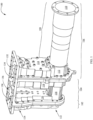
- FIG. 1 illustrates a diagram of an example waveguide feed network, according to some aspects of the disclosure.
- Waveguide feed network 100 includes transmit section 106, receive section 102, and a body section 104. As shown in the figure, body section 104 includes first lower portion 116, first upper portion 118, and second upper portion 120.
- Transmit section 106 of waveguide feed network 100 includes second lower portion 112 and third upper portion 114.
- First upper portion 118, third upper portion 114, first lower portion 116, and second lower portion 112 may together include a transmitter unit that is described in more details with respect to FIG. 3 as transmitter unit 300.
- receive section 102 of waveguide feed network 100 includes third lower portion 122 and fourth upper portion 124.
- Second upper portion 120, fourth upper portion 124, first lower portion 116, and third lower portion 122 may together include a receive unit that is described in more details with respect to FIG. 6 as receiver unit 600.
- transmit section 106 of FIG. 1 includes core waveguide 110 having an outer body 108 that is coupled to second lower portion 112.
- core waveguide 110 may extend from outer body 108 of transmit section 106, through second lower portion 112 of transmit section 106, and through first lower portion 116 of body section 104 to third lower portion 122 of receive section 102.
- a diameter of core waveguide 110 may change one or more times when passing through outer body 108 to third lower portion 122.
- core waveguide 110 is a circular waveguide. In some other examples, core waveguide 110 is a cruciform waveguide.
- the transmitter unit shown in FIG. 3 , comprises two segments. A first segment of the transmitter unit is included in first upper portion 118 and first lower portion 116 of body section 104 and a second segment of the transmitter unit is included in third upper portion 114 and second lower portion 112 of transmit section 106. Thus, the transmitter unit is formed when transmit section 106 and body section 104 are connected to each other. In some examples, connecting transmit section 106 and body section 104 also forms two input ports 132 and 134. In some examples, the transmitter unit receives a signal through one of input ports 132 and 134 that causes the transmitter unit to transmit a circularly polarized wave through core waveguide 110.
- the transmitter unit receives signal through input port 132 and transmits a right hand circularly polarized wave through core waveguide 110. In some examples, transmitter unit receives the signal through input port 134 and transmits a left hand circularly polarized wave through core waveguide 110. In some examples, waveguide feed network 100 provides an isolation of better than 25 dB between input ports 132 and 134 of the transmitter unit.
- the receiver unit shown in FIG. 6 , comprises two segments. A first segment of the receiver unit is included in second upper portion 120 and first lower portion 116 of body section 104 and a second segment of the receiver unit is included in fourth upper portion 124 and third lower portion 122 of receive section 102. Thus, the receiver unit is formed when receive section 102 and body section 104 are connected to each other. In some examples, connecting receive section 102 and body section 104 also forms two output ports 136 and 138. In some examples, the receiver unit receives a circularly polarized wave through core waveguide 110 that causes the receiver unit to generate a signal at one output ports 136 or 138.
- the receiver unit receives a right hand circularly polarized wave and generates a signal at output port 136. In some examples, the receiver unit receives a left hand circularly polarized wave and generates a signal at output port 138.
- waveguide feed network 100 provides an isolation of better than 25 dB between output ports 136 and 138 of the receive unit. In some examples, waveguide feed network 100 is a compact and low complexity excitation assembly for generating /receiving a circular polarization in/from core waveguide 110. In some examples, waveguide feed network 100 is made of aluminum.
- FIG. 2 illustrates a perspective view of a body section of an example waveguide feed network, according to some aspects of the disclosure.
- body section 104 includes first lower portion 116 that includes a first segment of core waveguide 202 having perimeter 204.
- second lower portion 112 of transmit section 106 includes a complementary second segment of core waveguide 202 that together with the first segment of core waveguide 202, when body section 104 is connected to transmit section 106, form core waveguide 202 of the transmitter unit.
- Core waveguide 202 is described with respect to FIGS. 7 and 8 .
- Body section 104 also includes first upper portion 118 that includes a plurality of openings with length 206 that make a first segment of a plurality of rectangular waveguides that are described in more details with respect to FIG. 3 as transmitter unit 300.
- the first segment of the plurality of rectangular waveguides forms the first segment of the transmitter unit which also includes a first segment of input ports 132 and 134.
- third upper portion 114 of transmit section 106 includes a plurality of similar openings that make a complementary second segment of the plurality of rectangular waveguides that form the complementary second segment of the transmitter unit.
- first segment of a plurality of rectangular waveguides in first upper portion 118 and the second segment of a plurality of rectangular waveguides in third upper portion 114 are symmetrical with respect an outer surface of first upper portion 118 and thus a zero electric field is generated at the outer surface of first upper portion 118.
- a length of the plurality of rectangular waveguides of the transmitter unit is twice length 206.
- FIG. 3 illustrates a cross sectional diagram of an example transmitter unit, according to some aspects of the disclosure.
- a perspective view of transmitter unit 300 is shown with respect to FIG. 7 .
- a linearly polarized input signal is received through one of input ports 132 or 134 and circularly polarized signal is generated in core waveguide 202.
- An operation of transmitter unit 300 is described with respect to FIG. 10 .
- transmitter unit 300 is a cross sectional surface through waveguide feed network 100 of Fig. 1 , e.g., along a contact surface between body section 104 and transmit section 106 as shown in FIG. 2 .
- Transmitter unit 300 shows core waveguide 202 with perimeter 204 around core waveguide 202 as shown in FIG.
- diameter D2 of the core waveguide of waveguide feed network 100 is smaller at the receiver unit compared to diameter D1 at the transmitter unit.
- the smaller diameter of the core waveguide at the receiver provides a higher cut off frequency for the receiver unit compared to the transmitter unit.
- Transmitter unit 300 shows two branches 310A and 310B that are coupled to core waveguide 202.
- Each one of branch 310A or 310B includes waveguide reject filter 312A or 312B that includes one or more stubs, e.g., three stubs.
- FIG. 3 shows three single-sides stubs 302A, 302C, and 302E on branch 310A as well as three single-sides stubs 302B, 302D, and 302F on branch 310B. As shown the stubs are protruding outward.
- the waveguide filters are waveguide reject filters that are implemented to prevent signals in certain frequency bands to reach input ports 132 and 134 of FIGS.
- waveguide reject filters 312A or 312B are low pass filters and the sizes of filters 312A and 312B including the sizes of stubs 302A, 302B, 302C, 302D, 302E, and 302F as well as a number of the stubs may be determined based on an allowed wavelength and a rejection band of the waveguide reject filters.
- waveguide reject filters 312A and 312B suppress a signal in a predetermined range that is received via the core waveguide from reaching input ports 132 and 134.
- the C band is used for receiving and transmitting signals and allowed frequency ranges and stop (e.g., suppressed) frequency ranges of the transmitter unit are predefined.
- a transmitting frequency band includes frequencies 4.120 GHz to 4.20 GHz that may pass from input ports 132 or 134 to core waveguide 202.
- the receiving frequency band includes frequencies 6.345 GHz to 6.425 GHz that are suppressed, e.g., by more than 55 dB, from reaching input ports 132 or 134 from the core waveguide.
- an isolation of better than 55 dB may be achieved for input ports 132 and 132 from undesired signals in the core waveguide that are in the receiving frequency band.
- a free end of stubs 302A, 302B, 302C, 302D, 302E, and 302F may be short-circuited. Then an input impedance of a short-circuited stub is purely reactive; either capacitive or inductive, depending on the electrical length and width of the stubs and a wavelength of signal passing through waveguide reject filters 312A or 312B.
- Stubs may thus function as capacitors and inductors in waveguide reject filters 312A or 312B and may be used to tune a bandwidth of waveguide reject filters 312A or 312B.
- more than three stubs, e.g., five stubs may be integrated into the waveguide reject filters of each branch to further shape a frequency response of waveguide reject filters.
- transmitter unit 300 shows two evanescent waveguides 304A and 304B that are coupled between branches 310A and 310B and core waveguide 202.
- a size of evanescent waveguides 304A and 304B are adjusted such an insertion loss between core waveguide 202 and the waveguide reject filters 312A and 312B of branches 310A and 310B are less than a predetermined level, e.g., less than 0.05 dB, in each branch.
- evanescent waveguides 304A and 304B of first and second branches 310B and 310A of transmitter unit 300 have predetermined angles, e.g., 45 degrees, when coupled to the core waveguide.
- the 45-degree turns of evanescent waveguides 304A and 304B may cause a supposed continuation of branches 310A and 310B to intersect each other at a center of core waveguide 202 with an angle A equal to 90 degrees.
- the ends of the branches 310A and 310B coupled to the core waveguide 202 may become perpendicular to each other.
- the 45-degree turn may allow integrated branch line coupler 316 to stay close to core waveguide 502, reducing a size and mass of transmitter unit 300 to make it compact.
- transmitter unit 300 shows transformers 306A, 306B, 306C, and 306D on branches 310A and 310B.
- the transformers have dimensions that are determined based on a frequency range of the transmitted signals that may be input at input ports 132 and 134 and to minimize an insertion loss of the transmitter unit.
- the one or more transformers of each branch 310A or 310B are quarter wave transformers that are configured to provide a change of wavelength for matching.
- transformers 306A, 306B, 306C, and 306D to change the wavelength, branches 310A or 310B may match to a transmitter circuit that can be coupled to input ports 132 and 134.
- quarter wave transformer WR229 may be used.
- waveguide reject filters 312A and 312B of branches 310A and 310B of transmitter unit 300 are low pass filters.
- Waveguide reject filters 312A and 312B may transmit received input signals at a first frequency, e.g., in a range between 4.120 GHz and 4.20 GHz, from input ports 132 and 134 to core waveguide 202.
- the waveguide reject filters may reject a second signal at a second frequency greater than the first frequency, e.g., in a range between 6.345 GHz and 6.425 GHz.
- waveguide reject filters 312A and 312B may prevent a received second signal in the second frequency from core waveguide 202 to reach input ports 132 and 134.
- Transmitter unit 300 shows integrated branch line coupler 316 that includes couplers 314A, 314B, and 314C that inwardly couple branches 310A and 310B.
- Integrated branch line coupler 316 also includes waveguide reject filters 312A and 312B that are described above.
- a number, size, and location of couplers 314A, 314B, and 314C may be selected to create left hand circular polarization as well as right hand circular polarization signals in core waveguide 202.
- the circular polarization signals are created based on the linearly polarized signals that are received from input ports 132 and 134 of branches 310A and 310B.
- waveguide reject filters 312A or 312B have an inner face and an outer face.
- couplers 314A, 314B, and 314C are coupled between the inner face of waveguide reject filters 312A or 312B.
- integrated branch line coupler 316 provides splitting a power by 3dB and a 90 degrees phase shift to generate a circular polarization mode from a linear polarization mode.
- width 322 of couplers 314A, 314B, and 314C can provide the 90 degrees phase shift.
- Waveguide reject filters 312A or 312B of integrated branch line coupler 316 may isolate an unwanted circular polarization mode to get to input ports 132 or 134.
- integrated branch line coupler 316 may also provide a predetermined axial ratio, e.g., 0.40 dB axial ratio, over a bandwidth of up to 9 percent, between the left hand and right hand circularly polarized signals.
- a distance between couplers 314A, 314B, and 314C depends on diameter D1 of core waveguide 202.
- couplers 314A, 314B, and 314C are e-plane couplers and a height of the couplers may determine an amount of energy that may be transferred between the branches.
- height 318 of coupler 314B determines an amount of energy that may be transferred between the branches 310A and 310B.
- Integrated branch line coupler 316 is described with respect to FIG. 4 .
- stubs 302A, 302B, 302C, 302D, 302E, and 302F are coupled to and extended from the outer face of waveguide reject filters 312A or 312B.
- the one or more single-sided stubs 302A, 302B, 302C, 302D, 302E, and 302F of waveguide reject filters 312A and 312B correspond to one or more cascaded filter sections. As shown in FIG. 3 , one or more single-sided stubs 302A, 302B, 302C, 302D, 302E are coupled outwardly to waveguide reject filters 312A or 312B.
- couplers 314A, 314B, and 314C are coupled inwardly to waveguide reject filters 312A or 312B in between a location of the one or more single-sided stubs.
- waveguide reject filters 312A and 312B allows a signal being in frequency range 4.12 GHz to 4.2 GHz to pass, e.g., from input ports 132 and 134 to core waveguide 202.
- waveguide reject filters 312A and 312B suppresses a signal being in frequency range 6.345 GHz to 6.425 GHz to pass, e.g., from core waveguide 202 to any of input ports 132 and 134, and provide at least a 35 dB isolation.
- integrated branch line coupler 316 generates, at core waveguide 202, one or both of a right hand circularly polarized signal and a left hand circularly polarized signal from a linearly polarized signal.
- transmitter unit 300 receives an input signal at a first frequency from input port 132 of first branch 310B and generates a right hand circularly polarized signal at the first frequency in core waveguide 202.
- transmitter unit 300 receives an input signal at a first frequency from input port 134 of second branch 310A and generates a left hand circularly polarized signal at the first frequency in the core waveguide.
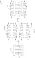
- FIG. 4 illustrates components of an example integrated branch line coupler, according to some aspects of the disclosure.
- Diagram 400 of FIG. 4 shows integrated branch line coupler 416 that is consistent with integrated branch line coupler 316 of FIG. 3 .
- integrated branch line coupler 416 is an integration of branch line coupler 410 and portions of corrugated low pass filters 412A and 412B.
- Branch line coupler 410 may have a plurality of couplers 414.
- Corrugated low pass filters 412A and 412B may have a plurality of stubs 406.
- Integrated branch line coupler 416 may be viewed as an integration of branch line coupler 410, upper half of corrugated low pass filter 412A, and lower half of corrugated low pass filter 412B.
- integrated branch line coupler 416 may be viewed as an integration of branch line coupler 410 and one of the corrugated low pass filters 412A or 412B.
- the plurality of couplers 414 and the plurality of stubs 406 do not face each other when coupled in integrated branch line coupler 416.
- integrated branch line coupler 416 performs functions of filtering as well as dividing power and providing phase shift to create linearly polarized signals.
- FIG. 5 illustrates a perspective view of a receive section of an example waveguide feed network, according to some aspects of the disclosure.
- receive section 102 includes third lower portion 122 that includes core waveguide 502 having perimeter 320.
- third lower portion 122 of receive section 102 includes a complementary second segment of core waveguide 502 that together with the first segment of core waveguide 502 form core waveguide 502 of the receiver unit.
- a diameter of core waveguide 110 changes, e.g., is reduced, between the transmitter unit and the receiver unit such that core waveguide 502, which is a portion of core waveguide 110, has a smaller diameter compared to anther portion of core waveguide 110, which is core waveguide 202.
- Core waveguides 202 and 502 are described in more details with respect to FIGS. 7 and 8 .
- Receive section 102 also includes fourth upper portion 124 that includes a plurality of openings with length 506 that make a first segment of a plurality of rectangular waveguides that are described in more details with respect to FIG. 6 as receiver unit 600.
- the first segment of the plurality of rectangular waveguides forms the first segment of the receiver unit which also includes a first segment of output ports 136 and 138.
- second upper portion 120 of body section 104 includes a plurality of similar openings that make a complementary second segment of the plurality of rectangular waveguides that form the complementary second segment of the receiver unit.
- the first segment of a plurality of rectangular waveguides in fourth upper portion 124 and the second segment of a plurality of rectangular waveguides in second upper portion 120 are symmetrical with respect to an outer surface of fourth upper portion 124 and thus a zero electric field is generated at the outer surface of fourth upper portion 124.
- a length of the plurality of rectangular waveguides of the transmitter unit is twice length 506.
- FIG. 6 illustrates a cross sectional diagram of an example receiver unit, according to some aspects of the disclosure.
- a perspective view of receiver unit 600 is shown with respect to FIG. 7 .
- receiver unit 600 shows a cross sectional surface through waveguide feed network 100 of Fig. 1 , e.g., along a contact surface between body section 104 and receive section 102 as shown in FIG. 2 .
- Receiver unit 600 shows core waveguide 502 with perimeter 320 around core waveguide 502 as shown in FIG. 5 .
- core waveguide 502 has diameter D2 shown also in FIG. 3 .
- circularly polarized signals are received through core waveguide 502 via branches 610A and 610B that are coupled to core waveguide 502.
- the received signals pass through filters 612A and 612B as well as couplers 614A, 614B, and 614C, and generate a linearly polarized signal.
- the linearly polarized signal may be generated at one of output ports 136 or 138 depending on the signal being right hand circularly polarized or left hand circularly polarized, respectively.
- an isolation of better than 25 dB is provided between output ports 136 and 138.
- waveguide reject filters 612A and 612B allows a signal being in frequency 6.345 GHz to 6.425 GHz to pass, e.g., from core waveguide 502 to one of output ports 136 and 138.
- waveguide reject filters 612A and 612B suppresses a signal being in frequency range 4.12 GHz to 4.2 GHz to pass, e.g., from core waveguide 502 to any of output ports 136 and 138, and provides at least 55 dB isolation.
- Receiver unit 600 includes two branches 610A and 610B that are coupled to core waveguide 502. Each one of branch 610A or 610B includes waveguide reject filters 612A or 612B.
- Waveguide reject filters 612A and 612B may have dimensions that are determined based on a frequency of the transmitted signals, and may act as transmit reject filters.
- Waveguide filters 612A and 612B may also be called waveguide reject filters 612A and 612B that suppress rectangular mode TE10 in the frequency range of 4.120 GHz and 4.20 GHz.
- waveguide reject filters 612A and 612B may perform a filtering, e.g., high pass filtering, to suppress the transmitter signals and further prevent the transmitter signals from reaching output ports 136 or 138 of the receiver unit.
- Receiver unit 600 shows integrated branch line coupler 616 that includes couplers 614A, 614B, and 614C that inwardly couples branches 610A and 610B.
- Integrated branch line coupler 616 also includes waveguide reject filters 612A or 612B that are described above.
- a number, size, and location of the couplers 614A, 614B, and 614C may be selected to transform left hand circular polarization as well as right hand circular polarization signals at core waveguide 502 to linearly polarized signals at output ports 136 and 138 of branches 610A and 610B.
- a distance between couplers 614A, 614B, and 614C depends on diameter D2 of core waveguide 502.
- couplers 614A, 614B, and 614C are e-plane couplers.
- the waveguide filters e.g., waveguide reject filters 612A or 612B have an inner face and an outer face.
- integrated branch line coupler 616 comprises couplers 614A, 614B, and 614C that are coupled between the inner face of the waveguide reject filters 612A or 612B. As described, integrated branch line coupler 616 may divide power and generate phase shift to create linearly polarized signals from circularly polarized signals.
- couplers 614A, 614B, and 614C of integrated branch line coupler 616 generates a linearly polarized signal at a first frequency from a circularly polarized signal at the first frequency.
- the integrated branch line coupler provides, splitting a power by 3dB, causing 90 degrees phase shift to generate a linear polarization from a circular polarization mode, and isolating a signal to get to the other port.
- receiver unit 600 shows transformers 606A, 606B, 606C, and 606D on branches 610A and 610B.
- the transformers have dimensions that are determined based on a frequency of the received signals from the core waveguide and to minimize an insertion loss of the receiver unit at output ports 136 and 138.
- the one or more transformers of each branch 610A or 610B are quarter wave transformers that are configured to provide a change of wavelength for matching.
- transformers 606A, 606B, 606C, and 606D to change wavelength, branches 610A or 610B may match to a receiver circuit that can be coupled to output ports 136 and 138.
- quarter wave transformer WR137 may be used.
- the circularly polarized signal is received from core waveguide 502 and the linearly polarized signal is generated at an output of waveguide reject filters 612A and 612B that is coupled to a transformer.
- receiver unit 600 receives a right hand circularly polarized signal at a first frequency from core waveguide 502 and generates an output signal at the first frequency at output port 136 of second branch 610B.
- receiver unit 600 receives a left hand circularly polarized signal at a first frequency from core waveguide 502 and generates an output signal at the first frequency at output port 138 of first branch 610A.
- branches 610A or 610B have a 45-degree turn, e.g., bend, at an end that attaches to core waveguide 502.
- the 45-degree turn may allow integrated branch line coupler 616 to stay close to core waveguide 502, reducing a size and mass of receiver unit 600 and creating a compact receiver unit.
- placing integrated branch line coupler 616 close to core waveguide 502 may allow more effective impedance matching between core waveguide 502 and receiver unit 600.
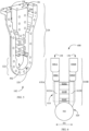
- FIG. 7 illustrates a perspective view of an example waveguide feed network, according to some aspects of the disclosure.
- diagram 700 of FIG. 7 shows core waveguide 202 of the transmitter unit.
- Core waveguide 202 is consistent with a portion of core waveguide 110 of FIG. 1 that is coupled to branches 310A and 310B.
- FIG. 7 also shows core waveguide 502 of the receiver unit that is consistent with a portion of core waveguide 110 of FIG. 1 that is coupled to branches 610A and 610B.
- Core waveguides 202 and 502 are coupled together via core waveguide 710 extended between the transmitter unit and receiver unit inside first lower portion 116 of body section 104. A diameter of core waveguides 202, 710, and 502 are described with respect to FIG.
- Diagram 700 also shows core waveguide 110 that is extended outward.
- waveguide feed network 100 receives signals from input ports 132 and 134 and transmits circularly polarized signals through core waveguide 110.
- waveguide feed network 100 receives signals from core waveguide 110 and provides output signals through output ports 136 and 138.
- Diagram 700 additionally shows a perspective view of branches 310A and 310B of the transmitter unit that include input ports 132 and 134 and a perspective view of branches 610A and 610B of the receiver unit that include output ports 136 and 138.
- FIG. 8 illustrates a side view of an example waveguide feed network, according to some aspects of the disclosure.
- diagram 800 of FIG. 8 is a side view of diagram 700 of FIG. 7 that shows a side view of branch 310A of the transmitter unit and a side view of branch 610A of the receiver unit.
- Diagram 800 also includes core waveguide 202 and core waveguide 502 coupled together via core waveguide 710.
- diameter D2 of core waveguide 502 of the receiver unit is smaller than diameter D1 of core waveguide 202 of the transmitter unit. Consequently, core waveguide 502 of the receiver unit may have a higher cutoff frequency for waveguide propagation modes compared to the cutoff frequency of core waveguide 202 of the transmitter unit.
- diameter D1 of core waveguide 202 is reduced through core waveguide 710 to match diameter D2 of core waveguide 502 in one or more steps, e.g., in one step.
- the transmitter unit has length L1
- the receiver unit has length L2
- the transmitter unit and the receiver unit are separated by length L3.
- dimensions of waveguide feed network 100 depends on a frequency of operation of waveguide feed network 100.
- transmitting and receiving frequencies are selected in C band.
- D1 is selected in a first range between 1.70 inches and 1.73 inches, e.g., D1 is selected at 1.72 inches. By selecting D1 in the first range, the cutoff frequency for TE21 mode in core waveguide 202 stays between 6.64 GHz and 6.76 GHz.
- the higher frequency F4 is sufficiently, e.g., by at least 1 percent below the lower cutoff frequency.
- TE21 mode may not propagate in the core waveguide 202 of waveguide feed network 100 in the transmitting frequency range of F1 to F2 or receiving frequency range of F3 to F4.
- D2 being smaller than D1
- TE21 mode may not also propagate in the core waveguide 502 in the transmitting frequency range of F1 to F2 or receiving frequency range of F3 to F4.
- the cutoff frequency for TE11 mode in core waveguide 202 may be between 4.0 GHz and 4.07 GHz.
- the lower frequency F1 is at least above the higher cutoff frequency of 4.07 GHz by more than 1 percent.
- L1 is selected between 1.44 inches and 1.835 inches, e.g., 1.806 inches, such that no TE20 or TE30 modes can propagate in rectangular waveguides of waveguide reject filters 312A and 312B.
- TE10 mode is sufficiently out of a cutoff frequency in the rectangular waveguides of transmitter unit 300 and thus may propagate through transmitter unit 300 to core waveguide 202.
- D2 is selected between 1.2 inches and 1.54 inches, e.g., 1.354 inches, such that in core waveguides 710 and 502 the TE11 mode is sufficiently in cutoff for F2 and clearly for F1.
- D2 is selected such that F3 and clearly F4 are sufficiently out of cutoff for TE11 mode in core waveguides 710 and 502.
- L3 is selected longer than 1.55 inches, e.g., 1.598 inches, such that a greater that 40 dB suppression may be obtained for TM01 mode in the core waveguide between the transmitter unit and receiver unit.
- FIG. 9A illustrates an image of an example waveguide feed network, according to some aspects of the disclosure.
- image 900 of FIG. 9A shows an example manufactured body of waveguide feed network 100.
- Image 900 shows outer body 108 of core waveguide 110, second lower portion 112, first lower portion 116, and third lower portion 122.
- Image 900 also shows input ports 132 and 134 as well as output port 136 and 138.
- the transmitter unit and the receiver unit are not at a same side of waveguide feed network 100 and may even be at the opposite sides.
- input ports 132 and 134 as well as output port 136 and 138 are at opposite sides of waveguide feed network 100 and the openings to the output ports and input ports may have different orientations.
- FIG. 9B illustrates an image of an example waveguide feed network, according to some aspects of the disclosure.
- image 950 of FIG. 9B shows an example manufactured body of waveguide feed network 100.
- Image 950 shows outer body 108 of core waveguide 110, second lower portion 112, first lower portion 116, and third lower portion 122.
- Image 950 also shows output port 136 and 138.
- Input ports 132 and 134 are respectively coupled through waveguides 952 and 954 to transmitter circuits (not shown) such the input signal may be connected through connection 956.
- a plurality of transmitter units 300 may be included in waveguide feed network 100.
- the plurality of transmitter units 300 may be coupled to core waveguide 110 and may operate at a plurality of first distinct transmitting frequencies.
- a plurality of receiver units may be included in waveguide feed network 100.
- the plurality of receiver units 600 may be coupled to core waveguide 110 and may operate at a plurality of second distinct receiving frequencies different from and greater that the plurality of first distinct transmitting frequencies.
- core waveguide 110 is designed to suppress a propagation of TE21 in the core waveguide.
- a diameter of the core waveguide is reduced from the transmitter unit to the receiver unit to suppress transmitting frequencies of the transmitter unit in TE11 mode from reaching the receiver.
- Reduced diameter D2 of core waveguide 110 at the receiver unit 600 and length L3 of core waveguide 110 between transmitter unit 300 and receiver unit 600 may also prevents the TM01 mode from reaching the receiver unit.
- TM01 mode is reduced in the core waveguide by more than 40 dB to prevent disrupting an antenna pattern.
- FIG. 10 illustrates a flow diagram of an example method of operation of a waveguide feed network, according to some aspects of the disclosure. Notably, one or more steps of method 1000 described herein may be omitted, performed in a different sequence, and/or combined with other methods for various types of applications contemplated herein. Method 1000 can be performed to operate transmitter unit 300 of FIG. 3 . As shown in FIG. 2 , transmitter unit 300 may be coupled between two input ports 132 and 134 and core waveguide 202 and may receive linearly polarized input signals from the input ports. Transmitter unit 300 may generate circularly polarized signal in core waveguide 202.
- a transmitter unit receives a first linearly polarized signal by an input port.
- the transmitter unit includes two branches each having an input port.
- the transmitter unit receives the first linearly polarized signal from input port 132 of first branch 310B.
- a portion of the first linearly polarized signal is transmitted via a first waveguide reject filter to a circular waveguide.
- a first half of the first linearly polarized signal is transmitted to the circular waveguide.
- the portion of the first linearly polarized signal is transmitted through first waveguide reject filter 312B of first branch 310B to core waveguide 202 that may be a circular waveguide.
- first waveguide reject filter 312B is part of integrated branch line coupler 316 that is located in first branch 310B.
- one or more transformers 306B and 306D are coupled between input port 132 and first waveguide reject filter 312B to provide a change of wavelength for matching.
- an evanescent waveguide e.g., evanescent waveguide 304B of FIG. 3 , couples first waveguide reject filter 312B to core waveguide 202.
- a second linearly polarized signal is generated by providing a quarter wavelength phase shift to a remaining portion of the first linearly polarized signal.
- the a quarter wavelength phase shift is provided by a transmission of the remaining portion of the first linearly polarized signal to second branch 310A through couplers 314A, 314B, and 314C of integrated branch line coupler 316.
- Couplers 314A, 314B, and 314C are inwardly coupled between first waveguide reject filter 312B and second waveguide reject filter 312A.
- a second half of the first linearly polarized signal that is transmitted to second waveguide reject filter 312A receives 90 degrees phase shift.
- the second linearly polarized signal is transmitted via a second waveguide reject filter to a circular waveguide.
- the second linearly polarized signal is generated from the second half of the first linearly polarized signal.
- the second half of the first linearly polarized signal is transmitted through couplers 314A, 314B, and 314C of integrated branch line coupler 316 and receives 90 degrees phase shift.
- the second linearly polarized signal is transmitted through second waveguide reject filter 312A of second branch 310A to core waveguide 202.
- second waveguide reject filter 312A is part of integrated branch line coupler 316 that is located in second branch 310A.
- an evanescent waveguide e.g., evanescent waveguide 304A of FIG. 3 , couples second waveguide reject filter 312A to core waveguide 202.
- first branch 310B and second branch 310A are coupled to core waveguide 202 via evanescent waveguides 304A and 304B at separate predefined locations of core waveguide 202 to generate the circularly polarized signal in core waveguide 202.
- first linearly polarized signal is received through input port 132
- a right hand circularly polarized signal is generated in core waveguide 202 and additionally input port 134 is isolated by better than 25 dB.
- a left hand circularly polarized signal is generated in core waveguide 202 and additionally input port 132 is isolated by better than 25 dB.
Landscapes
- Waveguide Switches, Polarizers, And Phase Shifters (AREA)
- Control Of Motors That Do Not Use Commutators (AREA)
Claims (15)
- Speisenetzwerk (100), aufweisend:
eine erste Sendereinheit (300), die aufweist:einen ersten Zweig (310B) mit einer ersten Eingangsöffnung (132) und einen zweiten Zweig (310A) mit einer zweiten Eingangsöffnung (134);einen ersten integrierten Zweigleitungskoppler (316), der den ersten Zweig (310B) und zweiten Zweig (310A) koppelt, wobei der erste integrierte Zweigleitungskoppler (316) aufweist:einen ersten Wellenleiter-Sperrfilter (312B) im ersten Zweig (310B), aufweisend ein erstes Ende und ein zweites Ende sowie eine Außenfläche und eine Innenfläche, wobei das erste Ende des ersten Wellenleiter-Sperrfilters (312B) mit der ersten Eingangsöffnung (132) gekoppelt ist;einen zweiten Wellenleiter-Sperrfilter (312A) im zweiten Zweig (310A), aufweisend ein erstes Ende und ein zweites Ende sowie eine Außenfläche und eine Innenfläche, wobei das erste Ende des zweiten Wellenleiter-Sperrfilters (312A) mit der zweiten Eingangsöffnung (134) gekoppelt ist;eine erste Gruppe aus einem oder mehreren Kopplern (314A, 314B, 314C), die zwischen der Innenfläche des ersten Wellenleiter-Sperrfilters (312B) und der Innenfläche des zweiten Wellenleiter-Sperrfilters (312A) gekoppelt sind; undeine erste Gruppe aus einem oder mehreren einseitigen Blindbereichen (302B, 302D, 302F), die von der Außenfläche des ersten Wellenleiter-Sperrfilters (312B) nach außen vorstehen, und eine zweite Gruppe aus einem oder mehreren einseitigen Blindbereichen (302A, 302C, 302E), die von der Außenfläche des zweiten Wellenleiter-Sperrfilters (312A) nach außen vorstehen; undeinen Kernwellenleiter (202), der über das zweite Ende des ersten Wellenleiter-Sperrfilters (312B) mit dem ersten Zweig (310B) und über das zweite Ende des zweiten Wellenleiter-Sperrfilters (312A) mit dem zweiten Zweig (310A) gekoppelt ist;wobei die erste Gruppe aus einem oder mehreren Kopplern (314A, 314B, 314C) zwischen Positionen der ersten und zweiten Gruppe aus einem oder mehreren einseitigen Blindbereichen (302A, 302B, 302C, 302D, 302E, 302F) innerlich gekoppelt ist, undwobei die ersten Sendereinheit (300) dafür ausgelegt ist, von der ersten Eingangsöffnung (132) oder der zweiten Eingangsöffnung (134) her ein linear polarisiertes Signal zu empfangen und im Kernwellenleiter (202) ein zirkular polarisiertes Signal zu erzeugen. - Speisenetzwerk (100) nach Anspruch 1, wobei der Kernwellenleiter (202) ein zirkularer Wellenleiter ist.
- Speisenetzwerk (100) nach Anspruch 1, wobei die erste Gruppe aus einem oder mehreren Kopplern (314A, 314B, 314C) der ersten Sendereinheit (300) dafür ausgelegt ist, eine 90 Grad betragende Phasenverschiebung zu erzeugen, wenn zwischen dem ersten und zweiten Zweig (310A, 310B) ein linear polarisiertes Signal gesendet wird.
- Speisenetzwerk (100) nach Anspruch 1, wobeidie erste Sendereinheit (300) dafür ausgelegt ist, ein Eingangssignal mit einer ersten Frequenz von der ersten Eingangsöffnung (132) des ersten Zweigs (310B) her zu empfangen und ein rechtsdrehend zirkular polarisiertes Signal mit der ersten Frequenz im Kernwellenleiter (202) zu erzeugen; unddie erste Sendereinheit (300) dafür ausgelegt ist, ein Eingangssignal mit einer ersten Frequenz von der zweiten Eingangsöffnung (134) des zweiten Zweigs (310A) her zu empfangen und ein linksdrehend zirkular polarisiertes Signal mit der ersten Frequenz im Kernwellenleiter (202) zu erzeugen.
- Speisenetzwerk (100) nach Anspruch 1, wobei die erste Gruppe aus einem oder mehreren einseitigen Blindbereichen (302B, 302D, 302F) einer ersten Gruppe aus einem oder mehreren kaskadierten Filterbereichen im ersten Wellenleiter-Sperrfilter (312B) entspricht, und wobei die zweite Gruppe aus einem oder mehreren einseitigen Blindbereichen (302A, 302C, 302E) einer zweiten Gruppe aus einem oder mehreren kaskadierten Filterbereichen im zweiten Wellenleiter-Sperrfilter (312A) entspricht.
- Speisenetzwerk (100) nach Anspruch 1, wobei es sich bei dem ersten und zweiten Wellenleiter-Sperrfilter (312A, 312B) der ersten Sendereinheit (300) um Tiefpassfilter handelt, die dafür ausgelegt sind, ein empfangenes Eingangssignal mit einer ersten Frequenz von der ersten oder zweiten Eingangsöffnung (134) her zu senden und ein zweites Signal, das von dem Kernwellenleiter (202, 502) mit einer zweiten Frequenz empfangen wird, die größer als die erste Frequenz ist, zu sperren; und
wobei das Speisenetzwerk (100) darüber hinaus aufweist:
eine erste Empfängereinheit (600), die dafür ausgelegt ist, mit dem Kernwellenleiter (202, 502) gekoppelt zu sein, um ein zirkular polarisiertes Signal vom Kernwellenleiter (202, 502) her zu empfangen, wobei die erste Empfängereinheit (600) aufweist:einen dritten Zweig mit einer ersten Ausgangsöffnung und einen vierten Zweig mit einer zweiten Ausgangsöffnung;einen zweiten integrierten Zweigleitungskoppler, der den dritten Zweig und vierten Zweig koppelt, wobei der zweite integrierte Zweigleitungskoppler aufweist:einen dritten Wellenleiter-Sperrfilter im dritten Zweig, aufweisend ein erstes Ende und ein zweites Ende sowie eine Außenfläche und eine Innenfläche, wobei das erste Ende des dritten Wellenleiter-Sperrfilters dafür ausgelegt ist, mit dem Kernwellenleiter (202, 502) gekoppelt zu sein, und das zweite Ende des dritten Wellenleiter-Sperrfilters dafür ausgelegt ist, mit der ersten Ausgangsöffnung gekoppelt zu sein;eine vierten Wellenleiter-Sperrfilter im vierten Zweig, aufweisend ein erstes Ende und ein zweites Ende sowie eine Außenfläche und eine Innenfläche, wobei das erste Ende des vierten Wellenleiter-Sperrfilters dafür ausgelegt ist, mit dem Kernwellenleiter (202, 502) gekoppelt zu sein, und das zweite Ende des vierten Wellenleiter-Sperrfilters dafür ausgelegt ist, mit der zweiten Ausgangsöffnung gekoppelt zu sein; undeine zweite Gruppe aus einem oder mehreren Kopplern, die zwischen der Innenfläche des dritten Wellenleiter-Sperrfilters und der Innenfläche des vierten Wellenleiter-Sperrfilters gekoppelt sind,wobei die erste Empfängereinheit (600) dafür ausgelegt ist, über die ersten Enden des dritten und vierten Wellenleiter-Sperrfilters vom Kernwellenleiter (202, 502) her ein zirkular polarisiertes Signal der zweiten Frequenz zu empfangen und an der ersten Ausgangsöffnung oder zweiten Ausgangsöffnung ein linear polarisiertes Signal der zweiten Frequenz zu erzeugen. - Speisenetzwerk (100) nach Anspruch 6, darüber hinaus aufweisend:eine oder mehrere Sendereinheiten zusätzlich zu der ersten Sendereinheit (300), wobei die erste Sendereinheit (300) und die eine oder die mehreren Sendereinheiten jeweils mit dem Kernwellenleiter (202, 502) gekoppelt und dafür ausgelegt sind, auf zwei oder mehr verschiedenen Sendefrequenzen zu arbeiten; undeine oder mehrere Empfängereinheiten zusätzlich zu der ersten Empfängereinheit (600), wobei die erste Empfängereinheit (600) und die eine oder die mehreren Empfängereinheiten jeweils mit dem Kernwellenleiter (202, 502) gekoppelt und dafür ausgelegt sind, auf zwei oder mehr verschiedenen Empfangsfrequenzen zu arbeiten, die sich von den verschiedenen Sendefrequenzen unterscheiden und höher als diese sind,wobei ein Durchmesser des Kernwellenleiters (202, 502) so gewählt ist, dass eine Fortpflanzung eines TE21-Mode im Kernwellenleiter (202, 502) in einem ersten vorbestimmten Bereich, der Sendefrequenzen zugehörig ist, und in einem zweiten vorbestimmten Bereich, der Empfangsfrequenzen zugehörig ist, unterbunden ist, wobei sich der Durchmesser des Kernwellenleiters (202, 502) von der ersten Sendereinheit (300) zur ersten Empfängereinheit (600) verkleinert, um zu unterbinden, dass ein TM01-Mode im ersten vorbestimmten Bereich die erste Empfängereinheit (600) erreicht.
- Speisenetzwerk (100) nach Anspruch 1, wobei eine erste Gruppe aus einem oder mehreren Umwandlern zwischen der ersten Eingangsöffnung (132) und dem ersten Ende des ersten Wellenleiter-Sperrfilters (312B) und eine zweite Gruppe aus einem oder mehreren Umwandlern zwischen der zweiten Eingangsöffnung (134) und dem ersten Ende des zweiten Wellenleiter-Sperrfilters (312A) gekoppelt sind, und wobei es sich bei der ersten und zweiten Gruppe aus einem oder mehreren Umwandlern um Viertelwellen-Umwandler handelt, die dafür ausgelegt sind, eine Größenänderung für einen rechteckigen Wellenleiter bereitzustellen.
- Speisenetzwerk (100) nach Anspruch 1, wobei der erste Zweig (310B) mit dem Kernwellenleiter (202) über einen ersten evaneszenten Wellenleiter gekoppelt ist, der zwischen dem zweiten Ende des ersten Wellenleiter-Sperrfilters (312B) und dem Kernwellenleiter (202) gekoppelt ist, wobei der zweite Zweig (310A) mit dem Kernwellenleiter (202) über einen zweiten evaneszenten Wellenleiter gekoppelt ist, der zwischen dem zweiten Ende des zweiten Wellenleiter-Sperrfilters (312B) und dem Kernwellenleiter (202) gekoppelt ist, und wobei der erste und zweite evaneszente Wellenleiter vorbestimmte Winkel haben, wenn sie mit dem Kernwellenleiter (202) gekoppelt sind.
- Empfängereinheit (600), aufweisend:einen zirkularen Wellenleiter;eine erste und eine zweite Gruppe aus einem oder mehreren Umwandlern;einen ersten Zweig (310B) mit einer ersten Ausgangsöffnung und einen zweiten Zweig (310A) mit einer zweiten Ausgangsöffnung;einen integrierten Zweigleitungskoppler, der den ersten Zweig (310B) und zweiten Zweig (310A) koppelt, wobei der integrierte Zweigleitungskoppler aufweist:einen ersten Wellenleiter-Sperrfilter (312B) im ersten Zweig (310B), aufweisend ein erstes Ende und ein zweites Ende sowie eine Außenfläche und eine Innenfläche, wobei das erste Ende des ersten Wellenleiter-Sperrfilters (312B) dafür ausgelegt ist, mit dem zirkularen Wellenleiter gekoppelt zu sein;einen zweiten Wellenleiter-Sperrfilter (312A) im zweiten Zweig (310A), aufweisend ein erstes Ende und ein zweites Ende sowie eine Außenfläche und eine Innenfläche, wobei das erste Ende des zweiten Wellenleiter-Sperrfilters (312A) dafür ausgelegt ist, mit dem zirkularen Wellenleiter gekoppelt zu sein, wobei die erste Gruppe aus einem oder mehreren Umwandlern zwischen der ersten Ausgangsöffnung und dem zweiten Ende des ersten Wellenleiter-Sperrfilters (312B) und die zweite Gruppe aus einem oder mehreren Umwandlern zwischen der zweiten Ausgangsöffnung und dem zweiten Ende des zweiten Wellenleiter-Sperrfilters (312A) gekoppelt sind; undeine oder mehrere Koppler, die zwischen der Innenfläche des ersten Wellenleiter-Sperrfilters (312B) und der Innenfläche des zweiten Wellenleiter-Sperrfilters (312A) gekoppelt sind,wobei der integrierte Zweigleitungskoppler dafür ausgelegt ist, über die ersten Enden des ersten und zweiten Wellenleiter-Sperrfilters (312A, 312B) vom zirkularen Wellenleiter her ein zirkular polarisiertes Signal zu empfangen und an der ersten Ausgangsöffnung oder zweiten Ausgangsöffnung ein linear polarisiertes Signal zu erzeugen.
- Empfängereinheit (600) nach Anspruch 10, wobei der eine oder die mehreren Koppler dafür ausgelegt sind, eine 90 Grad betragende Phasenverschiebung zu erzeugen, wenn ein linear polarisiertes Signal zwischen dem ersten und zweiten Zweig (310A, 310B) gesendet wird.
- Empfängereinheit nach Anspruch 10, wobei:die Empfängereinheit (600) dafür ausgelegt ist, ein rechtsdrehend zirkular polarisiertes Signal mit einer ersten Frequenz vom zirkularen Wellenleiter her zu empfangen und ein Ausgangssignal mit der ersten Frequenz an der ersten Ausgangsöffnung des ersten Zweigs (310B) zu erzeugen; unddie Empfängereinheit (600) dafür ausgelegt ist, ein linksdrehend zirkular polarisiertes Signal mit einer zweiten Frequenz vom zirkularen Wellenleiter her zu empfangen und ein Ausgangssignal mit der zweiten Frequenz an der zweiten Ausgangsöffnung des zweiten Zweigs (310A) zu erzeugen.
- Empfängereinheit (600) nach Anspruch 10, wobei es sich bei dem ersten und zweiten Wellenleiter-Sperrfilter (312A, 312B) um Hochpassfilter handelt.
- Empfängereinheit (600) nach Anspruch 10, wobei es sich bei der ersten und zweiten Gruppe aus einem oder mehreren Umwandlern um Viertelwellen-Umwandler handelt, die dafür ausgelegt sind, eine Größenänderung für einen rechteckigen Wellenleiter bereitzustellen.
- Verfahren zum Betreiben einer Sendereinheit, wobei die Sendereinheit einen ersten Zweig (310B) und einen zweiten Zweig (310A) hat, wobei das Verfahren umfasst:Empfangen eines ersten linear polarisierten Signals von einer Eingangsöffnung (132) des ersten Zweigs (310B);Ändern einer Wellenlänge des ersten linear polarisierten Signals unter Verwendung eines Viertelwellenlängenwandlers;Senden eines ersten Teils des ersten linear polarisierten Signals über einen ersten Wellenleiter-Sperrfilter (312B) des ersten Zweigs (310B) an einen zirkularen Wellenleiter;Erzeugen eines zweiten linear polarisierten Signals durch Bereitstellung einer Viertelwellenlängen-Phasenverschiebung an einem verbleibenden zweiten Teil des ersten linear polarisierten Signals, und zwar über ein Senden des verbleibenden zweiten Teils des ersten linear polarisierten Signals an den zweiten Zweig (310A) durch einen Zweigleitungskoppler, der zwischen dem ersten Wellenleiter-Sperrfilter (312B) und einem zweiten Wellenleiter-Sperrfilter (312A) des zweiten Zweigs (310A) gekoppelt ist;Senden des zweiten linear polarisierten Signals über den zweiten Wellenleiter-Sperrfilter (312A) an den zirkularen Wellenleiter; undZusammenführen, im zirkularen Wellenleiter, des ersten Teils des ersten linear polarisierten Signals und des zweiten linear polarisierten Signals, um ein rechtsdrehend oder linksdrehend zirkular polarisiertes Signal im zirkularen Wellenleiter zu erzeugen.
Applications Claiming Priority (3)
| Application Number | Priority Date | Filing Date | Title |
|---|---|---|---|
| US201762460042P | 2017-02-16 | 2017-02-16 | |
| US15/895,983 US10297920B2 (en) | 2017-02-16 | 2018-02-13 | Compact dual circular polarization multi-band waveguide feed network |
| PCT/US2018/018515 WO2018152417A1 (en) | 2017-02-16 | 2018-02-16 | Compact dual circular polarization multi-band waveguide feed network |
Publications (3)
| Publication Number | Publication Date |
|---|---|
| EP3583661A1 EP3583661A1 (de) | 2019-12-25 |
| EP3583661A4 EP3583661A4 (de) | 2020-12-23 |
| EP3583661B1 true EP3583661B1 (de) | 2024-11-06 |
Family
ID=63104850
Family Applications (1)
| Application Number | Title | Priority Date | Filing Date |
|---|---|---|---|
| EP18754081.0A Active EP3583661B1 (de) | 2017-02-16 | 2018-02-16 | Kompaktes duales zirkulares polarisations-mehrbandwellenleiter-speisenetzwerk |
Country Status (4)
| Country | Link |
|---|---|
| US (1) | US10297920B2 (de) |
| EP (1) | EP3583661B1 (de) |
| JP (1) | JP7015313B2 (de) |
| WO (1) | WO2018152417A1 (de) |
Families Citing this family (6)
| Publication number | Priority date | Publication date | Assignee | Title |
|---|---|---|---|---|
| US11177580B2 (en) * | 2018-11-06 | 2021-11-16 | Lockheed Martin Corporation | Multiband linear waveguide feed network |
| US10763593B1 (en) * | 2018-11-07 | 2020-09-01 | Lockheed Martin Corporation | Broadband single pol TX, dual pol RX, circular polarization waveguide network |
| CN109818155B (zh) * | 2019-03-26 | 2020-12-11 | 东南大学 | 一种波束独立可控的双圆极化毫米波反射阵天线 |
| CN110277635B (zh) * | 2019-06-17 | 2021-01-01 | 北京达顺威尔科技有限公司 | 三频多极化导航测控天线馈源 |
| US11693166B2 (en) | 2020-08-10 | 2023-07-04 | Lockheed Martin Corporation | Septumless OMT polarizer |
| CN112993544B (zh) * | 2021-02-04 | 2022-02-18 | 上海航天测控通信研究所 | 一种x频段多极化多通道微波组件 |
Family Cites Families (21)
| Publication number | Priority date | Publication date | Assignee | Title |
|---|---|---|---|---|
| US3056096A (en) * | 1956-05-23 | 1962-09-25 | Varian Associates | Multiplexer apparatus |
| US4041420A (en) * | 1976-06-30 | 1977-08-09 | Riblet Henry J | Shunted stepped waveguide transition |
| US4968957A (en) * | 1989-05-31 | 1990-11-06 | Hughes Aircraft Company | Transmit and receive diplexer for circular polarization |
| JPH0478206A (ja) * | 1990-07-18 | 1992-03-12 | Hitachi Ltd | 高周波回路 |
| JPH09186506A (ja) * | 1995-10-31 | 1997-07-15 | Nec Eng Ltd | 分波器 |
| WO2001020733A1 (en) * | 1999-09-10 | 2001-03-22 | Nikon Corporation | Light source and wavelength stabilization control method, exposure apparatus and exposure method, method for producing exposure apparatus, and device manufacturing method and device |
| GB0023269D0 (en) * | 2000-09-22 | 2000-11-08 | Invacom Ltd | Improvements to data receiving apparatus |
| JP3622673B2 (ja) * | 2000-12-22 | 2005-02-23 | 株式会社村田製作所 | 誘電体フィルタ、誘電体デュプレクサ及び通信装置 |
| US6577207B2 (en) * | 2001-10-05 | 2003-06-10 | Lockheed Martin Corporation | Dual-band electromagnetic coupler |
| WO2005029719A2 (fr) * | 2003-09-18 | 2005-03-31 | Thomson Licensing | Terminal utilisateur bi-directionnel de large diffusion à fréquences d'émission configurables |
| US7408427B1 (en) * | 2004-11-12 | 2008-08-05 | Custom Microwave, Inc. | Compact multi-frequency feed with/without tracking |
| US8953647B1 (en) * | 2007-03-21 | 2015-02-10 | Lockheed Martin Corporation | High-power laser using thulium-doped fiber amplifier and frequency quadrupling for blue output |
| US7737904B2 (en) * | 2008-06-11 | 2010-06-15 | Lockheed Martin Corporation | Antenna systems for multiple frequency bands |
| FR2939971B1 (fr) | 2008-12-16 | 2011-02-11 | Thales Sa | Ensemble d'excitation compact pour la generation d'une polarisation circulaire dans une antenne et procede d'elaboration d'un tel ensemble d'excitation |
| US8514140B1 (en) * | 2009-04-10 | 2013-08-20 | Lockheed Martin Corporation | Dual-band antenna using high/low efficiency feed horn for optimal radiation patterns |
| AU2011326337B2 (en) * | 2010-11-08 | 2015-05-28 | Bae Systems Australia Limited | Antenna system |
| US8994473B2 (en) * | 2010-12-30 | 2015-03-31 | Orbit Communication Ltd. | Multi-band feed assembly for linear and circular polarization |
| JP5822635B2 (ja) * | 2011-10-07 | 2015-11-24 | 三菱電機株式会社 | アンテナ給電回路 |
| US9178285B2 (en) * | 2012-05-25 | 2015-11-03 | General Dynamics C4 Systems, Inc. | Phase shift device and method |
| FR2993716B1 (fr) | 2012-07-20 | 2016-09-02 | Thales Sa | Antenne d'emission et de reception multifaisceaux a plusieurs sources par faisceau, systeme d'antennes et systeme de telecommunication par satellite comportant une telle antenne |
| US10197736B2 (en) * | 2015-12-09 | 2019-02-05 | Chiral Photonics, Inc. | Polarization maintaining optical fiber array |
-
2018
- 2018-02-13 US US15/895,983 patent/US10297920B2/en active Active
- 2018-02-16 EP EP18754081.0A patent/EP3583661B1/de active Active
- 2018-02-16 JP JP2019544022A patent/JP7015313B2/ja active Active
- 2018-02-16 WO PCT/US2018/018515 patent/WO2018152417A1/en not_active Ceased
Also Published As
| Publication number | Publication date |
|---|---|
| US10297920B2 (en) | 2019-05-21 |
| WO2018152417A1 (en) | 2018-08-23 |
| EP3583661A1 (de) | 2019-12-25 |
| JP2020508009A (ja) | 2020-03-12 |
| JP7015313B2 (ja) | 2022-02-02 |
| US20180233829A1 (en) | 2018-08-16 |
| EP3583661A4 (de) | 2020-12-23 |
Similar Documents
| Publication | Publication Date | Title |
|---|---|---|
| EP3583661B1 (de) | Kompaktes duales zirkulares polarisations-mehrbandwellenleiter-speisenetzwerk | |
| CA1216640A (en) | Directional coupler for separation of signals in two frequency bands while preserving their polarization characteristics | |
| US6661309B2 (en) | Multiple-channel feed network | |
| CA1260609A (en) | Wide bandwidth multiband feed system with polarization diversity | |
| CA2659345C (en) | Compact orthomode transduction device optimized in the mesh plane, for an antenna | |
| US6473053B1 (en) | Dual frequency single polarization feed network | |
| CN111295798A (zh) | 正交模转换器 | |
| WO2012172565A1 (en) | Wideband waveguide turnstile junction based microwave coupler and monopulse tracking feed system | |
| US9954265B2 (en) | Two-transmitter two-receiver antenna coupling unit for microwave digital radios | |
| CN114400447A (zh) | 一种双频共馈系统 | |
| US11228116B1 (en) | Multi-band circularly polarized waveguide feed network | |
| US7332982B2 (en) | Waveguide diplexer of electric plane T-junction structure with resonant iris | |
| EP2345099B1 (de) | Wellenleiterantennen-frontend | |
| CN114188688B (zh) | 一种小型化同轴波导正交模耦合器 | |
| EP3345247A1 (de) | Kompakte antennenzuleitung mit dualer polarisation | |
| US10069184B2 (en) | Compact and lightweight TEM-line network for RF components of antenna systems | |
| EP4391216A1 (de) | Vorrichtung und system zum teilen und kombinieren von signalen im frequenzbereich | |
| JP2016134639A (ja) | 偏波分離回路 | |
| US11728553B1 (en) | Dual-band waveguide feed network | |
| US11710907B1 (en) | Clone carousel waveguide feed network | |
| KR101491723B1 (ko) | 커플러를 이용한 이중 대역 피드혼 | |
| EP0400833A2 (de) | Sende-Empfangs-Diplexer für zirkulare Polarisation | |
| RU2292098C1 (ru) | Многочастотная облучающая система зеркальной антенны с разделением ортогональных поляризаций | |
| KR950004803B1 (ko) | 원형편파 4/6GHz 위성 통신용 다이프랙서 장치 | |
| Prata et al. | A High Performance-Wide Band-Diplexing-Tracking-Depolarization Correcting Satellite Communication Antenna Feed |
Legal Events
| Date | Code | Title | Description |
|---|---|---|---|
| STAA | Information on the status of an ep patent application or granted ep patent |
Free format text: STATUS: THE INTERNATIONAL PUBLICATION HAS BEEN MADE |
|
| PUAI | Public reference made under article 153(3) epc to a published international application that has entered the european phase |
Free format text: ORIGINAL CODE: 0009012 |
|
| STAA | Information on the status of an ep patent application or granted ep patent |
Free format text: STATUS: REQUEST FOR EXAMINATION WAS MADE |
|
| 17P | Request for examination filed |
Effective date: 20190910 |
|
| AK | Designated contracting states |
Kind code of ref document: A1 Designated state(s): AL AT BE BG CH CY CZ DE DK EE ES FI FR GB GR HR HU IE IS IT LI LT LU LV MC MK MT NL NO PL PT RO RS SE SI SK SM TR |
|
| AX | Request for extension of the european patent |
Extension state: BA ME |
|
| DAV | Request for validation of the european patent (deleted) | ||
| DAX | Request for extension of the european patent (deleted) | ||
| A4 | Supplementary search report drawn up and despatched |
Effective date: 20201125 |
|
| RIC1 | Information provided on ipc code assigned before grant |
Ipc: H01P 1/213 20060101ALI20201119BHEP Ipc: H01Q 13/02 20060101AFI20201119BHEP Ipc: H01P 1/209 20060101ALI20201119BHEP Ipc: H04B 1/00 20060101ALI20201119BHEP Ipc: H01P 1/17 20060101ALI20201119BHEP Ipc: H01P 5/00 20060101ALI20201119BHEP Ipc: H01P 1/20 20060101ALI20201119BHEP |
|
| STAA | Information on the status of an ep patent application or granted ep patent |
Free format text: STATUS: EXAMINATION IS IN PROGRESS |
|
| 17Q | First examination report despatched |
Effective date: 20230508 |
|
| GRAP | Despatch of communication of intention to grant a patent |
Free format text: ORIGINAL CODE: EPIDOSNIGR1 |
|
| STAA | Information on the status of an ep patent application or granted ep patent |
Free format text: STATUS: GRANT OF PATENT IS INTENDED |
|
| INTG | Intention to grant announced |
Effective date: 20240603 |
|
| GRAS | Grant fee paid |
Free format text: ORIGINAL CODE: EPIDOSNIGR3 |
|
| GRAA | (expected) grant |
Free format text: ORIGINAL CODE: 0009210 |
|
| STAA | Information on the status of an ep patent application or granted ep patent |
Free format text: STATUS: THE PATENT HAS BEEN GRANTED |
|
| AK | Designated contracting states |
Kind code of ref document: B1 Designated state(s): AL AT BE BG CH CY CZ DE DK EE ES FI FR GB GR HR HU IE IS IT LI LT LU LV MC MK MT NL NO PL PT RO RS SE SI SK SM TR |
|
| REG | Reference to a national code |
Ref country code: GB Ref legal event code: FG4D |
|
| REG | Reference to a national code |
Ref country code: CH Ref legal event code: EP |
|
| REG | Reference to a national code |
Ref country code: DE Ref legal event code: R096 Ref document number: 602018076276 Country of ref document: DE |
|
| P01 | Opt-out of the competence of the unified patent court (upc) registered |
Free format text: CASE NUMBER: APP_58840/2024 Effective date: 20241028 |
|
| REG | Reference to a national code |
Ref country code: IE Ref legal event code: FG4D |
|
| REG | Reference to a national code |
Ref country code: LT Ref legal event code: MG9D |
|
| REG | Reference to a national code |
Ref country code: NL Ref legal event code: MP Effective date: 20241106 |
|
| PG25 | Lapsed in a contracting state [announced via postgrant information from national office to epo] |
Ref country code: HR Free format text: LAPSE BECAUSE OF FAILURE TO SUBMIT A TRANSLATION OF THE DESCRIPTION OR TO PAY THE FEE WITHIN THE PRESCRIBED TIME-LIMIT Effective date: 20241106 Ref country code: PT Free format text: LAPSE BECAUSE OF FAILURE TO SUBMIT A TRANSLATION OF THE DESCRIPTION OR TO PAY THE FEE WITHIN THE PRESCRIBED TIME-LIMIT Effective date: 20250306 Ref country code: IS Free format text: LAPSE BECAUSE OF FAILURE TO SUBMIT A TRANSLATION OF THE DESCRIPTION OR TO PAY THE FEE WITHIN THE PRESCRIBED TIME-LIMIT Effective date: 20250306 |
|
| PG25 | Lapsed in a contracting state [announced via postgrant information from national office to epo] |
Ref country code: FI Free format text: LAPSE BECAUSE OF FAILURE TO SUBMIT A TRANSLATION OF THE DESCRIPTION OR TO PAY THE FEE WITHIN THE PRESCRIBED TIME-LIMIT Effective date: 20241106 Ref country code: NL Free format text: LAPSE BECAUSE OF FAILURE TO SUBMIT A TRANSLATION OF THE DESCRIPTION OR TO PAY THE FEE WITHIN THE PRESCRIBED TIME-LIMIT Effective date: 20241106 |
|
| REG | Reference to a national code |
Ref country code: AT Ref legal event code: MK05 Ref document number: 1740430 Country of ref document: AT Kind code of ref document: T Effective date: 20241106 |
|
| PG25 | Lapsed in a contracting state [announced via postgrant information from national office to epo] |
Ref country code: BG Free format text: LAPSE BECAUSE OF FAILURE TO SUBMIT A TRANSLATION OF THE DESCRIPTION OR TO PAY THE FEE WITHIN THE PRESCRIBED TIME-LIMIT Effective date: 20241106 |
|
| PG25 | Lapsed in a contracting state [announced via postgrant information from national office to epo] |
Ref country code: ES Free format text: LAPSE BECAUSE OF FAILURE TO SUBMIT A TRANSLATION OF THE DESCRIPTION OR TO PAY THE FEE WITHIN THE PRESCRIBED TIME-LIMIT Effective date: 20241106 |
|
| PG25 | Lapsed in a contracting state [announced via postgrant information from national office to epo] |
Ref country code: NO Free format text: LAPSE BECAUSE OF FAILURE TO SUBMIT A TRANSLATION OF THE DESCRIPTION OR TO PAY THE FEE WITHIN THE PRESCRIBED TIME-LIMIT Effective date: 20250206 |
|
| PG25 | Lapsed in a contracting state [announced via postgrant information from national office to epo] |
Ref country code: LV Free format text: LAPSE BECAUSE OF FAILURE TO SUBMIT A TRANSLATION OF THE DESCRIPTION OR TO PAY THE FEE WITHIN THE PRESCRIBED TIME-LIMIT Effective date: 20241106 Ref country code: GR Free format text: LAPSE BECAUSE OF FAILURE TO SUBMIT A TRANSLATION OF THE DESCRIPTION OR TO PAY THE FEE WITHIN THE PRESCRIBED TIME-LIMIT Effective date: 20250207 Ref country code: AT Free format text: LAPSE BECAUSE OF FAILURE TO SUBMIT A TRANSLATION OF THE DESCRIPTION OR TO PAY THE FEE WITHIN THE PRESCRIBED TIME-LIMIT Effective date: 20241106 |
|
| PG25 | Lapsed in a contracting state [announced via postgrant information from national office to epo] |
Ref country code: PL Free format text: LAPSE BECAUSE OF FAILURE TO SUBMIT A TRANSLATION OF THE DESCRIPTION OR TO PAY THE FEE WITHIN THE PRESCRIBED TIME-LIMIT Effective date: 20241106 |
|
| PG25 | Lapsed in a contracting state [announced via postgrant information from national office to epo] |
Ref country code: RS Free format text: LAPSE BECAUSE OF FAILURE TO SUBMIT A TRANSLATION OF THE DESCRIPTION OR TO PAY THE FEE WITHIN THE PRESCRIBED TIME-LIMIT Effective date: 20250206 |
|
| PG25 | Lapsed in a contracting state [announced via postgrant information from national office to epo] |
Ref country code: SM Free format text: LAPSE BECAUSE OF FAILURE TO SUBMIT A TRANSLATION OF THE DESCRIPTION OR TO PAY THE FEE WITHIN THE PRESCRIBED TIME-LIMIT Effective date: 20241106 |
|
| PG25 | Lapsed in a contracting state [announced via postgrant information from national office to epo] |
Ref country code: DK Free format text: LAPSE BECAUSE OF FAILURE TO SUBMIT A TRANSLATION OF THE DESCRIPTION OR TO PAY THE FEE WITHIN THE PRESCRIBED TIME-LIMIT Effective date: 20241106 |
|
| PG25 | Lapsed in a contracting state [announced via postgrant information from national office to epo] |
Ref country code: EE Free format text: LAPSE BECAUSE OF FAILURE TO SUBMIT A TRANSLATION OF THE DESCRIPTION OR TO PAY THE FEE WITHIN THE PRESCRIBED TIME-LIMIT Effective date: 20241106 |
|
| PG25 | Lapsed in a contracting state [announced via postgrant information from national office to epo] |
Ref country code: RO Free format text: LAPSE BECAUSE OF FAILURE TO SUBMIT A TRANSLATION OF THE DESCRIPTION OR TO PAY THE FEE WITHIN THE PRESCRIBED TIME-LIMIT Effective date: 20241106 |
|
| PG25 | Lapsed in a contracting state [announced via postgrant information from national office to epo] |
Ref country code: SK Free format text: LAPSE BECAUSE OF FAILURE TO SUBMIT A TRANSLATION OF THE DESCRIPTION OR TO PAY THE FEE WITHIN THE PRESCRIBED TIME-LIMIT Effective date: 20241106 |
|
| PG25 | Lapsed in a contracting state [announced via postgrant information from national office to epo] |
Ref country code: CZ Free format text: LAPSE BECAUSE OF FAILURE TO SUBMIT A TRANSLATION OF THE DESCRIPTION OR TO PAY THE FEE WITHIN THE PRESCRIBED TIME-LIMIT Effective date: 20241106 |
|
| PG25 | Lapsed in a contracting state [announced via postgrant information from national office to epo] |
Ref country code: IT Free format text: LAPSE BECAUSE OF FAILURE TO SUBMIT A TRANSLATION OF THE DESCRIPTION OR TO PAY THE FEE WITHIN THE PRESCRIBED TIME-LIMIT Effective date: 20241106 |
|
| REG | Reference to a national code |
Ref country code: DE Ref legal event code: R097 Ref document number: 602018076276 Country of ref document: DE |
|
| REG | Reference to a national code |
Ref country code: DE Ref legal event code: R119 Ref document number: 602018076276 Country of ref document: DE |
|
| PG25 | Lapsed in a contracting state [announced via postgrant information from national office to epo] |
Ref country code: SE Free format text: LAPSE BECAUSE OF FAILURE TO SUBMIT A TRANSLATION OF THE DESCRIPTION OR TO PAY THE FEE WITHIN THE PRESCRIBED TIME-LIMIT Effective date: 20241106 |
|
| PLBE | No opposition filed within time limit |
Free format text: ORIGINAL CODE: 0009261 |
|
| STAA | Information on the status of an ep patent application or granted ep patent |
Free format text: STATUS: NO OPPOSITION FILED WITHIN TIME LIMIT |
|
| PG25 | Lapsed in a contracting state [announced via postgrant information from national office to epo] |
Ref country code: MC Free format text: LAPSE BECAUSE OF FAILURE TO SUBMIT A TRANSLATION OF THE DESCRIPTION OR TO PAY THE FEE WITHIN THE PRESCRIBED TIME-LIMIT Effective date: 20241106 |
|
| REG | Reference to a national code |
Ref country code: CH Ref legal event code: PL |
|
| 26N | No opposition filed |
Effective date: 20250807 |
|
| PG25 | Lapsed in a contracting state [announced via postgrant information from national office to epo] |
Ref country code: LU Free format text: LAPSE BECAUSE OF NON-PAYMENT OF DUE FEES Effective date: 20250216 |
|
| PG25 | Lapsed in a contracting state [announced via postgrant information from national office to epo] |
Ref country code: CH Free format text: LAPSE BECAUSE OF NON-PAYMENT OF DUE FEES Effective date: 20250228 |
|
| REG | Reference to a national code |
Ref country code: BE Ref legal event code: MM Effective date: 20250228 |
|
| PG25 | Lapsed in a contracting state [announced via postgrant information from national office to epo] |
Ref country code: DE Free format text: LAPSE BECAUSE OF NON-PAYMENT OF DUE FEES Effective date: 20250902 |
|
| PG25 | Lapsed in a contracting state [announced via postgrant information from national office to epo] |
Ref country code: FR Free format text: LAPSE BECAUSE OF NON-PAYMENT OF DUE FEES Effective date: 20250228 |
|
| PG25 | Lapsed in a contracting state [announced via postgrant information from national office to epo] |
Ref country code: BE Free format text: LAPSE BECAUSE OF NON-PAYMENT OF DUE FEES Effective date: 20250228 |
|
| PG25 | Lapsed in a contracting state [announced via postgrant information from national office to epo] |
Ref country code: IE Free format text: LAPSE BECAUSE OF NON-PAYMENT OF DUE FEES Effective date: 20250216 |
|
| PGFP | Annual fee paid to national office [announced via postgrant information from national office to epo] |
Ref country code: GB Payment date: 20260227 Year of fee payment: 9 |