EP3583839A2 - Dispositif de coupe - Google Patents
Dispositif de coupe Download PDFInfo
- Publication number
- EP3583839A2 EP3583839A2 EP19184934.8A EP19184934A EP3583839A2 EP 3583839 A2 EP3583839 A2 EP 3583839A2 EP 19184934 A EP19184934 A EP 19184934A EP 3583839 A2 EP3583839 A2 EP 3583839A2
- Authority
- EP
- European Patent Office
- Prior art keywords
- cutting device
- cutting
- handle
- elements
- force
- Prior art date
- Legal status (The legal status is an assumption and is not a legal conclusion. Google has not performed a legal analysis and makes no representation as to the accuracy of the status listed.)
- Granted
Links
Images


Classifications
-
- A—HUMAN NECESSITIES
- A01—AGRICULTURE; FORESTRY; ANIMAL HUSBANDRY; HUNTING; TRAPPING; FISHING
- A01G—HORTICULTURE; CULTIVATION OF VEGETABLES, FLOWERS, RICE, FRUIT, VINES, HOPS OR SEAWEED; FORESTRY; WATERING
- A01G3/00—Cutting implements specially adapted for horticultural purposes; Delimbing standing trees
- A01G3/02—Secateurs; Flower or fruit shears
- A01G3/033—Secateurs; Flower or fruit shears having motor-driven blades
- A01G3/037—Secateurs; Flower or fruit shears having motor-driven blades the driving means being an electric motor
Definitions
- the invention is based on a cutting device, in particular a garden cutting device, with at least a first and a second cutting element which can be moved relative to one another, with a first and a second handle element which can be moved relative to one another and with at least one drive unit which is provided for this purpose in at least one operating state to at least support the second cutting element relative to the first cutting element.
- the cutting device be designed to recognize an object between the handle elements in order to switch off the support operation.
- the cutting device is preferably designed as scissors, particularly preferably as garden shears.
- the two cutting edges movable relative to one another are pivotally mounted relative to one another.
- a “garden cutting device” is to be understood in particular to mean a cutting device which is intended for use on plants.
- this should in particular be understood to mean a cutting device which is provided for cutting plants, hedges, bushes, branches and / or other objects which appear sensible to a person skilled in the art.
- Under a "cutting element" in this Context to be understood in particular an element of the cutting device which is provided for direct contacting of an object to be cut.
- At least one of the cutting elements is passive, such as an anvil and / or a passive cutting edge.
- at least one cutting element preferably has an active cutting edge, in particular a blade, which is provided for active cutting.
- a “handle element” is to be understood in particular as an element that forms at least part of a handle. This is preferably to be understood to mean an element which is at least partially gripped by an operator in an operation. In an operation, both grip elements are preferably gripped by one operator, in particular with the same hand.
- An object is to be understood in particular as a hand, a finger, the skin of an operator, a branch or another object which can be damaged if it is inadvertently arranged between the grip elements, or which could damage the cutting device.
- the object detection should deactivate the support operation in at least one operating state, namely when an object is arranged between the grip elements.
- the deactivation of the movement support should also take place in an operating state in which, despite the arrangement of an object between the grip elements, an operating force is still exerted on the grip elements. This advantageously prevents injury to the operator and / or damage to the cutting device, since in such a state the grip elements have at least no additional support force zussamenSciencet. This increases the safety and ease of use of the cutting device.
- At least one sensor for object detection is arranged on the first or second handle element, in particular on an inside of the handle of the first or second handle element opposite the other handle element.
- the sensor is arranged in particular on the inner surfaces of the handle elements.
- the sensor can detect a force, a touch, a material or the like.
- radar-based, capacitive, inductive, optical, other proximity sensors or simply force or deformation sensors or the like come into consideration here.
- these sensors can transmit a signal to the control which communicates the detection of an object to a user optically, acoustically, tactilely or in some other way.
- the control preferably switches off the driving force support. Damage to the cutting device or injury to an operator or user can thus be avoided or prevented.
- a sensor for detecting the need for movement support be arranged on the first or second grip element in such a way that at least when an object is arranged between the grip elements, the support operation is switched off.
- the force sensor can, for example, sense the reaction force acting on the inside or inside surface of the handle elements through a pinched object or the path of the deformation of the handle elements.
- a relative movement or force of the grip element to a force transmission element movably mounted on or in the grip element can be sensed and, depending on this, the force support can be switched on or off.
- the force and / or displacement signal of the sensor is also advantageously used for safe and user-friendly control of the cutting device.
- a force transmission element which is connected in particular in a rotationally fixed manner to the second cutting element, is arranged is in operative connection with the drive unit and which is arranged to determine the movement support, in particular to determine whether the movement support is switched on or off, so as to be movable relative to the second grip element.
- the relative movement is detected at least one location between the force transmission element and the second grip element by means of a sensor.
- the cutting device can be controlled by means of the detected relative movement. This advantageously eliminates the need for electronic components, for example piezo sensors, proximity sensors or other sensors for direct object detection.
- the mechanical displacement or relative movement or indirect object detection can be detected in a simple manner, for example by a switch. This makes the device simpler and less prone to errors in electronic components.
- the relative movement is a pivoting movement of the force transmission element relative to the second grip element.
- the force transmission element can also be formed in one piece with the cutting element.
- such an arrangement allows the power support to be switched off in a particularly simple manner when an object is arranged between the handle elements despite the action of an operating force on the handle elements.
- the force transmission element advantageously extends from a pivot point in the front area of the second handle element facing the cutting elements to a central area of the second handle element. As a result, an easily measurable deflection of the force transmission element with respect to the grip element can be detected, the cutting device can be made stable but not too heavy.
- a deflection can be defined in a simple manner by the swivel joint and the overlapping length of the force transmission element or lever relative to the grip element, in particular within the grip element, which deflection can in turn be easily detected by sensors.
- a rotation or a rotational movement of the force transmission element relative to the grip element can be generated as a function of the operating force and detected by sensors.
- the second grip element have at least one relative movement limiting element.
- the relative movement limiting element is advantageously designed as a form-locking element.
- it can be a connecting element of the handle element constructed from half-shells, it can also be an inner wall of the handle element.
- the geometry of the force transmission element and the grip element is advantageously coordinated with one another in the region of the at least one relative movement limitation element.
- a sensor in particular a force or displacement sensor, detect the relative movement.
- the drive unit can advantageously be controlled or a state of the cutting device can be communicated to the operator.
- the senor have a spring and a switch as well as a support operating setting element which is arranged on the inside of the first or second handle element.
- the support operation setting element is designed, for example, as a slide switch.
- the sensitivity of the sensor or a drive support of the drive unit can be defined via the support operating setting element.
- the switch is arranged in particular on the force transmission element and the support mode setting element on the handle element, in particular displaceably on the inside of the handle element, in particular the inside of the second handle element opposite the first handle element. In this way, an inadvertent actuation of the support operating setting element or other switch can be avoided.
- the spring can also be designed to determine the sensitivity of the force sensor.
- a cutting device in particular a garden cutting device, is proposed with at least a first and a second cutting element which can be moved relative to one another, with a first and a second handle element which can be moved relative to one another and with at least one drive unit which is provided for this purpose in at least one operating state to at least support the second cutting element relative to the first cutting element, at least one of the grip elements being designed to avoid skin crushing, in particular at least partially elastic, round and / or beveled, at least on the inside of the grip.
- the inside of the handle is to be understood in particular as the facing inside of the handle.
- the handle elements are intended to touch.
- the elastic or rounded design of the inside of the handle can advantageously prevent undesired squeezing, in particular squeezing the skin of an operator's hand. This in turn lowers the safety of the cutting device.
- a cutting device in particular a garden cutting device, is proposed with at least a first and a second cutting element that can be moved relative to one another, with a first and a second gripping element that can be moved relative to one another and with at least one drive unit, which is provided for this purpose in at least one operating state to at least support the second cutting element relative to the first cutting element, a protective device being arranged between the handle elements between a swivel joint connecting the handle elements and an opening spring.
- the protective device delimits a space between the handle elements which, due to the large leverage ratios in this area, in particular when the support device of the cutting device is activated and for example an arrangement of a limb or another object, for example branches in this space, for injury to the operator and / or damage to the Can lead cutting device.
- the protective device makes the cutting device safer.
- the protective device receives a cable of the cutting device and / or forms a blocking device for blocking the intermediate space, which, in particular through the handle elements, the swivel joint and the opening spring is limited. This serves in particular to avoid at least inadvertently arranging an operator's limb, a finger, skin or an object in the intermediate space and likewise contributes to increasing the safety of the cutting device.
- a method for the cutting device is proposed, the support operation being switched off when an object is arranged between the handle elements of the cutting device, which increases the operational safety of the cutting device and reduces the risk of injury.
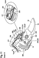
- FIG 1 shows a cutting device 10 according to the invention.
- the cutting device 10 is designed as a garden cutting device.
- the cutting device 10 is designed as secateurs.
- the cutting device is designed as a battery-operated cutting device 10. In principle, however, a different design of the cutting device 10 would also be conceivable, for example as a carpet or tin snips or the like.
- the cutting device 10 has two cutting elements 12, 14 which can be moved relative to one another ( Figure 2 . 3 ).
- the cutting elements 12, 14 can be pivoted relative to one another.
- a first cutting element 12 is designed as a passive cutting edge with a cutting edge.
- the second cutting element 14 is designed as an active cutting edge with a blade.
- the cutting device 10 has two grip elements 16, 18 which can be moved relative to one another.
- the grip elements 16, 18 can be pivoted or rotated relative to one another.
- the grip elements 16, 18 are designed to be pivotable relative to one another via at least one swivel joint 42.
- the cutting elements 12, 14 are also designed to be pivotable relative to one another via the swivel joint 42.
- the swivel joint 42 is arranged between the grip elements 16, 18 and the cutting elements 12, 14.
- the first grip element 16 and the first cutting element 12 are connected to one another and arranged on different sides of the swivel joint 42. Furthermore, the second grip element 18 and the second cutting element 14 are at least indirectly connected to one another and arranged on different sides of the swivel joint 42.
- a force transmission element 800 here in the form of a lever 80, connects the second cutting element 14 to the second grip element 18.
- the grip elements 16, 18 are provided to be gripped by an operator.
- the grip elements 16, 18 are intended to be gripped by an operator with the same hand. In principle, however, it would also be conceivable that the cutting device 10 is provided for two-handed operation. In this case, for example, further lever and or transmission elements could be provided in order to change a cutting force F cut at least partially relative to the force applied to the handle elements 16, 18, in particular an operating force F user .
- an opening spring 50 is arranged between the handle elements 16, 18.
- the opening spring 50 is arranged closer to the pivot joint 42 than to a free end of the handle elements 16, 18 in relation to a longitudinal extent of the handle elements 16, 18.
- the opening spring 50 is designed as a compression spring.
- the ends of the opening spring 50 are supported on the first and second handle elements 16, 18.
- the opening spring 50 is provided to press the handle elements 16, 18 apart and thus to open the cutting device 10.
- the opening spring 50 is also provided for receiving and / or guiding a driving force transmission element 340, here in the form of a cable 34, which is operatively connected to a drive unit 20, in a cavity formed by it, as will be explained further below.
- a protective device 300 is also arranged between the opening spring 50 and the swivel joint 42.
- the protective device 300 extends between the two handle elements 16, 18.
- the protective device 300 is advantageously firmly connected to the second handle element 18.
- the protective device 300 is also movably received in the first grip element 16.
- the protection device can for example, be designed as a telescopic device or as a rigid device.
- the protective device 300 is provided to protect at least one cable (not shown) of the cutting device 10, which is guided, for example, from the first into the second handle elements 16, 18 against external influences and / or securely between the first and second handle elements 16, 18 record.
- the cable is, for example, a cable for the electrical connection of an energy storage unit 54 and a control unit 52 and / or a drive unit 20 or a sensor cable which is routed from a 401 to the control unit 52.
- the protective device 300 also narrows an otherwise free space 301 between the swivel joint 42 and the opening spring 50, or at least partially fills it up, so that, for example, an operator can inadvertently insert his finger into this space with difficulty or a cut material, for example, may become stuck Branch or branch is difficult to catch in this space.
- the protective device 300 is also a blocking device for the intermediate space 301.
- the intermediate space 301 between the swivel joint 42 and the opening spring 50 is particularly dangerous for squeezing an object 17, in particular the fingers or the skin of an operator, since those acting in this area Forces due to the lever ratios or lever length of the grip elements 16, 18 around the swivel joint 42 are high.
- Protected device 300 can thus ensure protected and safe guidance of electronic components between handle elements 16, 18.
- the protective device 300 also serves to prevent injuries.
- the cutting device 10 has a drive unit 20.
- the drive unit 20 is designed as an electric motor.
- the electric motor is intended to be supplied with a voltage of less than 110 V, in particular with a voltage of 1 V to 36 V, preferably 3.6 V.
- the drive unit 20 is arranged in the first grip element 16.
- the drive unit 20 is arranged in a handle housing 44 of the handle element 16.
- the drive unit 20 is arranged on an end of the first handle element 16 facing away from the cutting elements 12, 14.
- the handle housing 44 has two housing shells in which the drive unit 20 is firmly accommodated.
- the drive unit 20 is provided for movement of the second cutting element 14 relative to the first cutting element 12.
- the drive unit 20 is provided to support a closing movement of the cutting device 10 carried out via the handle elements 16, 18 during heavy cutting work. As a result, a force F user required by an operator to actuate the cutting device 10 can be reduced.
- the cutting device 10 has a gear unit 38.
- the gear unit 38 is arranged in the first grip element 16.
- the gear unit 38 is arranged in the handle housing 44 of the handle element 16.
- the gear unit 38 is arranged on a side of the drive unit 20 facing the cutting elements 12, 14.
- the gear unit 38 is driven directly by the drive unit 20. Power is transmitted from the drive unit 20 to the gear unit 38 via an output shaft 21 of the output unit 20 to a pinion 82 of the gear unit 38.
- the gear unit 38 is designed as a gear unit.
- the gear unit 38 has at least one gear stage.
- the gear unit 38 advantageously has a plurality of gear stages.
- the gear unit 38 has in particular one to six gear stages, advantageously four gear stages.
- the at least one gear stage is designed as a planetary gear stage 381, 382, 383, 384.
- the gear unit 38 is designed as a planetary gear unit ( Figure 4 ).
- the gear ratio of the gear unit 38 advantageously has a ratio of 30: 1 to 300: 1, in particular 100: 1 to 150: 1, in particular 130: 1. In principle, however, a different translation would also be conceivable.
- the gear unit 38 is mounted in the handle element 16 via a housing 74 of the gear unit 38.
- the housing 74 of the gear unit 38 is formed by at least one ring gear 385 of the at least one planetary gear stage 381, 382, 383, 384.
- the housing 74 of the gear unit 38 can also be formed from individual series-arranged ring gears of the planetary gear stages 381, 382, 383, 384.
- the power transmission within the at least one planetary gear stage 381, 382, 383, 384 takes place in each case from a driven sun gear 386 via planets 387 of the respective planetary gear stage, which are supported on a fixed ring gear 381, to a planet carrier 388 rotating with the planets 387.
- the planet carrier 388 in turn drives a sun gear of the next gear stage 382, 383, 384.
- the planet carrier 389 of the last gear stage 384 forms the output of the gear unit 38.
- the cutting device 10 also has a coupling unit 22 ( Figure 4 and 5 ) on.
- the clutch unit 22 is designed as a self-switching clutch unit 22.
- a “self-switching clutch unit” is to be understood in particular to mean a clutch unit 22 which is actuated free of external, for example electrical switching signals, in particular a control unit 52.
- This is preferably to be understood to mean a clutch unit 22 which is actuated to switch between the clutch states free of explicit switching signals.
- the clutch unit 22 can therefore be designed in particular speed-operated, torque-operated, direction-operated and / or power flow-operated.
- the self-switching clutch unit 22 is designed as a one-way clutch.
- a “one-way clutch” is to be understood in particular to mean a self-shifting clutch which is designed to be directionally actuated and / or actuated by power flow.
- the one-way clutch is preferably at least directionally actuated.
- the one-way clutch is preferably provided to open and / or close depending on a direction of rotation, in particular a drive and / or driven side of the clutch unit 22, and / or depending on a direction of force acting on the one-way clutch.
- the one-way clutch is preferably provided to open or close the drive unit 20 in at least one operating state depending on a direction of rotation, in particular a drive and / or driven side, and / or depending on a direction of force acting on the one-way clutch.
- the coupling unit 22 is arranged in the first grip element 16.
- the coupling unit 22 is arranged in the handle housing 44 of the first handle element 16. In at least one operating state, in which the drive unit 20 is deactivated, the clutch unit 22 is provided for decoupling the drive unit 20.
- the drive unit 20 is automatically deactivated and the clutch unit 22 is automatically decoupled if there is no rotational movement of the drive unit 20.
- a “decoupling of the drive unit” is to be understood in particular as a decoupling of the drive unit 20 from a locking mechanism of the cutting device 10.
- the clutch unit 22 is also provided for decoupling the gear unit 38.
- the clutch unit 22 is provided, at least to implement complete manual operation, to decouple the drive unit 20 and / or the gear unit 38.
- “complete manual operation” is to be understood in particular to mean an operating state in which the cutting device 10 is operated without the support of the drive unit 20.
- This is preferably to be understood to mean an operating state in which the cutting device 10 is operated exclusively by the active force F user of an operator.
- This is particularly preferably to be understood to mean an operating state in which the drive unit 20 is decoupled and therefore cannot be used to support a movement of the second cutting element 14 relative to the first cutting element 12.
- This enables, in particular, advantageously smooth manual operation of the cutting device.
- the cutting device 10 can advantageously also be used without the drive unit 20, for example in the event of a lack of energy supply and / or for light cutting work.
- the coupling unit 22 is advantageously provided to accelerate the opening or spreading movement of the two cutting elements 12, 14 or the two handle elements 16, 18.
- the coupling unit 22 enables an accelerated rolling up and / or rolling off of a driving force transmission element 340, here in the form of a cable 34, from a cable winch 32 or cable drum 320 of a cable winch 32 when the cutting device 10 is opened or spread, as described further below becomes.
- a driving force transmission element 340 here in the form of a cable 34
- the operating speed of the cutting device or the processing speed can be increased and the operating convenience can be increased.
- the number of possible cuts per unit of time can be increased.
- the coupling unit 22 is provided for the drive unit 20 uncouple and to couple again with a new closing movement with motor power support.
- the clutch unit 22 has an inner rotating element 46 and an outer rotating element 48.
- the inner rotating element 46 is rotatable relative to the outer rotating element 48 in at least one state.
- the outer rotary element 48 is advantageously connected to the output of the gear unit 38.
- a part of the clutch unit 22 advantageously forms a part, in particular the last gear stage 384 of the gear unit 38.
- the outer rotary element 48 is advantageously formed in one piece with one part of the gear unit 38, in particular the planet carrier 389 of the last gear stage 384 and / or the output of the gear unit 38.
- the inner rotating element 46 and the outer rotating element 48 are secured to one another by means of an in particular coaxial connecting element 47.
- the connecting element 47 is designed as a connecting pin.
- the connecting element 47 secures the inner and outer rotating element 46, 48 at least axially and / or radially to one another.
- the connecting shaft 47 is preferably fixed, in particular frictionally connected to the outer rotating element 48 and, at least with rotational play, to the inner rotating element 46.
- the connecting shaft 47 is slidably received on the inner rotating element 46.
- the connecting shaft 47 also has a shoulder 471 for axially securing the inner rotating element 46 with respect to the outer rotating element 48.
- the shoulder 471 is supported on a particularly rim-like surface of the inner rotary element 46.
- the coupling unit 22 has a plurality of clamping bodies 24 ( Figure 6 and 7 ).
- a “clamping body” is to be understood in particular to mean an element of the coupling unit 22 which, in at least one operating state, in particular in a closed state of the coupling unit 22, is intended to be clamped between two rotating elements of the coupling unit 22 which are rotatably mounted relative to one another.
- the clamping bodies 24 are arranged between the inner rotating element 46 and the outer rotating element 48.
- the clamping bodies 24 are arranged one behind the other in the circumferential direction around the inner rotary element 46.
- the clamping bodies 24 are designed as cylinders and / or rollers, in particular as cylindrical rollers.
- the outer rotary element 48 has a plurality of ramps 49 which follow one another in the circumferential direction on its inside. A number of ramps 49 corresponds to a number of clamping bodies 24.
- the clamping bodies 24 are arranged movably between the ramps 49, the clamping bodies 24 being carried along when the outer rotary element 48 is rotated. If the outer rotary element 48 is driven in the circumferential direction against a ramp gradient, the clamping bodies 24 roll into a narrower region between the outer rotary element 48 and the inner rotary element 46 and are pressed against the inner rotary element 46.
- a “drive direction” is to be understood in particular to mean a direction of rotation of the drive unit 20 into which the drive unit 20 rotates in regular operation, in particular to support a cutting movement.
- the inner rotary element 46 is driven in rotation.
- the clutch unit 22 is closed in this state, as is shown in FIG Figure 6 is shown. If, on the other hand, the inner rotary element 46 is driven, regardless of a direction of rotation, the clamping bodies 24 remain in a valley of the ramps 49 or roll back into this and are spaced apart from the outer rotary element 48.
- the clamping bodies 24 are freely arranged between the rotating elements 46, 48. There is no turning entrainment.
- the clutch unit 22 is open in this state, as in the Figure 7 is shown.
- the outer rotary element 46 is driven by the drive unit 20 via the gear unit 38.
- the gear unit 38 and the drive unit 20 form a drive side of the clutch unit 22. If the inner rotary element 46 is driven counter to a drive direction 41, the clamping bodies 24 are moved into the valley of the ramps 49 and are likewise freely arranged between the rotary elements 46, 48.
- the self-switching clutch unit 22 is arranged spatially between the cutting elements 12, 14 and the drive unit 20.
- the self-switching clutch unit 22 is arranged spatially between a cable winch 32 and the gear unit 38. At least the cable winch 32 or an output element of the winch 32 forms an output of the clutch unit 22
- the self-switching clutch unit 22 has a cage 26 that receives the clamping bodies 24 ( Figure 6 . 7 ).
- the cage 26 takes the clamp body 24 in separate recording areas.
- the cage 26 serves to position and guide the clamping bodies 24 in the circumferential direction.
- the cage 26 is provided to space the clamping bodies 24 from one another in the circumferential direction and to distribute them evenly. In particular, it can be achieved with a plurality of clamping bodies 24 that the clamping bodies 24 perform the same movement in the circumferential direction. Controlled clamping of the clamping bodies 24 can preferably be made possible.
- the cage 26 is partially annular.
- the cage 26 is partially cylindrical. On a cylindrical base body of the cage 26, several axially projecting, segment-shaped webs are applied, which extend in the circumferential direction between the clamping bodies 24.
- the cage 26 is mounted on the inner rotating element 46 of the coupling unit 22.
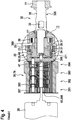
- the coupling unit 22 has a braking element 28 which is provided for braking the cage 26 ( Figure 8 ).
- the braking element 28 is designed as a spring element.
- the braking element 28 is designed as a kind of spiral spring.
- the braking element 28 is designed as a wrap spring.
- the braking element 28 is fixedly arranged at one end in a recess 29 of the cage 26.
- the braking element 28 extends at least partially in the circumferential direction spirally around the cage 26.
- the braking element 28 wraps around the cage 26.
- An outer surface of the braking element 28 is at least partially supported on a securing element 27 radially surrounding the braking element 28 or the cage 26.
- the securing element 27 is designed as a securing ring or fixing ring.
- the securing element 27 is fixedly arranged on the coupling unit 22.
- the securing element 27 is fixed, in particular at least rotationally fixed, preferably frictionally connected to the housing 23 of the coupling unit 22.
- the inner surface of the housing 23 is structured, in particular corrugated, in the area of the area provided for the arrangement of the securing element 27.
- the brake element 28 enables the cage 26 to rotate relative to the fixed handle housing 44 in one direction of rotation, in particular a drive direction of rotation, and blocks rotation of the cage 26 in the opposite direction of rotation.
- the brake element 28 enables the cage 26 to rotate relative to the housing 23 of the coupling unit 22 or to the securing element 27 in one direction and blocks rotation of the cage 26 in the opposite direction of rotation.
- the brake element 28 is designed to enable the cage 26 to run freely.
- the brake element 28 is designed to brake the cage 26 in the counter-drive direction 410 or to inhibit rotation or to fix the cage and to enable the cage 26 to rotate in the drive direction 41 relative to the outer support surface or the securing element 27, in particular to enable it with low friction.
- this type of loop coupling drags its free end with it and slides on the inner surface of the securing element 27.
- this type of loop coupling spreads and at least brakes or blocks the cage 26 relative to the Securing element 27.
- the braking element 28 is provided to prevent the cage 26 from being rotated unintentionally.
- the brake element 28 is provided to prevent the cage 26 from rotating until a force is exerted, in particular a force exerted by the drive unit 20.
- the braking element 28 can also be designed as a pawl element, another element that generates a freewheel, or the like.
- the inner rotating element 46 has at least one, in particular two, form-locking element 460, 460 '.
- the form-locking element is designed as a flange, but can also have a different shape.
- the cage 26 also has a form-locking element 260.
- the rotating body 370 has a form-locking element 370.
- the securing element 27 has at least one form-fitting element 270. At least via the form-fitting elements 260, 270, 370, 460, 460 'and sometimes frictional connections between the rotating body 37 and the inner rotating element 46, elements of the coupling unit 22 and the reset unit 31 are securely connected to one another. This ensures that these elements are axially secured to one another. The axial securing can also take place in another way.
- outer rotating element 48 is also axially secured to the inner rotating element 46 via the connecting element 47 and thus axially positioned to the coupling unit 22 via the securing element 27.
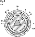
- the cutting device 10 has a reset unit 31 ( Figure 9 ).
- the reset unit 31 is arranged in the first grip element 16.
- the reset unit 31 is advantageously arranged in the handle housing 44 of the handle element 16.
- the resetting unit 31 is arranged in the coupling unit 22.
- the resetting unit 31 is preferably provided to ensure that the rope is tensioned.
- the reset unit 31 is preferably provided to apply a force, in particular a force, in the circumferential direction to the cable winch 32.
- the resetting unit 31 is particularly preferably provided to bring about a tensile force on the cable 34 via the cable winch 32.
- the cable 34 is to be kept permanently under tension via the reset unit 31.
- the restoring unit 31 preferably produces a restoring force F vs which is less than an opening force F os of the opening spring 50 (FIG. 3).
- the reset unit 31 can ensure tension of the cable 34, in particular even in the case of a complete manual operation. In this way, an undesired knotting of the rope 34 can advantageously be prevented. In addition, winding of the cable 34 can be ensured without a drive.
- the resetting unit 31 has a spring element 36 and a rotating body 37. One end of the spring element 36 is fixedly connected to the housing 23 of the coupling unit 22. The other end of the spring element 36 is fixedly connected to the rotating body 37. The spring element 36 is arranged radially between the housing 23 of the coupling unit 22 and the rotating body 37.
- the spring element 36 radially surrounds the rotating body 37.
- the spring element 36 is wound several times around the rotating body 37.
- the resetting unit 31 is at least indirectly connected to the cable winch 32 in particular via the rotating body 37.
- the rotating body 37 is fixed via the spring element 36 relative to the handle housing 44 or the housing 23 of the coupling unit 22 to a limited extent.
- the rotating body 37 is connected to the cable winch 32 via a shaft 35.
- the rotating body 37 is advantageously connected in a rotationally fixed manner via the shaft 35 to the inner rotating element 46 of the coupling unit 22.
- the rotating body 37 can be connected to the inner rotating element 46 via at least one radial and / or axial positive-locking element.
- the rotating body 37 has a coaxial recess.
- the recess is polygonal.
- the inner contour of the recess is designed to correspond to the outer contour of the shaft 35.
- the spring element 36 is provided to apply a force in the drive direction 41 to the shaft 35.
- the spring element 36 is provided for this purpose, the inner rotary element 46 to apply a force in the drive direction 41.
- the spring element 36 is provided to transmit a tensile force to the cable 34 via the cable winch 32.
- the cable 34 is to be kept permanently under tension, in particular tension, via the spring element 36.
- the spring element 36 can be pretensioned and fixed with an assembly aid 360 relative to the housing 23 of the clutch unit 23.
- the reset unit 31, in particular in connection with the clutch unit 22, can be installed as a pre-tensioned assembly.
- the clutch unit 22 can also be opened via the spring element 36 as soon as the drive motor is deactivated.
- the inner rotary element 46 can thus be rotated in the drive direction 41 via the spring element 36, which in turn allows the cage 26 to be braked via the brake element 28 as soon as the drive motor 20 is deactivated.
- An alternative reversal of the direction of rotation of the drive motor 20 for opening the clutch unit 22 can thus advantageously be avoided.
- the cutting device 10 has a cable winch 32 which can be driven by the drive unit 20.
- the cable winch 32 is arranged in the first grip element 16.
- the cable winch 32 is preferably designed to be drivable by the drive unit 20 via the coupling unit 22. In at least one operating state, the cable winch 32 is preferably designed to be decoupled from the drive unit 20 via the coupling unit 22.
- An advantageous force effect of the drive unit 20 can be achieved by the cable winch 32. In particular, this enables a movement of the second cutting element 14 relative to the first cutting element 12 to be supported in a structurally simple manner. An operator can thus advantageously be supported by the drive unit 20 during a closing movement. Furthermore, an advantageously high torque can be provided by the force of the drive unit on the grip elements 16, 18.
- the cable winch 32 is arranged in the handle housing 44 of the first handle element 16.
- the cable winch 32 is arranged on a side of the coupling unit 22 facing the cutting elements 12, 14.
- the cable winch 32 is connected to the shaft 35.
- the shaft 35 is advantageously formed in one piece with the cable winch 32.
- the shaft 35 is over bearings, in particular over Plain bearings 77, 77 'mounted.
- the bearing 77 facing the cutting elements 12, 14 is supported in the handle housing 44 of the handle element 16.
- the bearing 77 ′ facing away from the cutting element 12, 14 is supported in the housing 23 of the coupling unit 22.
- the shaft 35 is connected to the clutch unit 22.
- the shaft 35 is connected to the inner rotating element 46 in a rotationally fixed manner.
- the shaft 35 is also non-rotatably connected to the rotating body 37.
- the shaft 35 has a polygonal profile. It can also have a different profile for connecting to the coupling unit 22, for example a square, a tongue and groove profile or another shaft-hub connection profile. Because the cable winch 32 is connected directly to the inner rotating element 46 of the coupling unit 22 and the rotating body 37 of the reset unit and also connects these two elements to one another, the device is very compact.
- the self-switching clutch unit 22 can also be partially integrated into the cable winch 32.
- the clutch unit 22 can be partially gripped by the cable winch 32.
- the cable winch 32 forms an output side of the clutch unit 22.
- the cable winch 32 has a cable drum 320.
- the cable drum 320 is essentially cylindrical.
- An axial extension of the cable drum 320 is advantageously provided to roll up the cable 34 only in one layer.
- the axial extent of the cable drum 320 is advantageously 5-15 mm, in particular 6 mm.
- To position the cable 34 on the cable drum 320 the latter forms a shoulder at least on the side facing the swivel joint 42.
- the diameter of the cable drum 320 is advantageously less than 10 mm, in particular 7 mm.
- the cable winch 32 has a receptacle 33 for fixing the cable 34.
- the receptacle 33 is designed as an opening or as a through hole in the transverse axis direction of the cable winch 32 or shaft 35.
- the receptacle 33 has an at least substantially rectangular cross section.
- the receptacle 33 can also be oval, round, angular or the like.
- the receptacle 33 can have a clamp fit for the advantageously secure and compact reception of a rope end of the rope 34.
- the shaft 35 advantageously has a larger diameter than in the area of the cable drum 320. This is advantageously 8 mm.
- the cutting device 10 also has the rope 34.
- the cable 34 is preferably fixedly attached to the second handle element 18 and to the first handle element 18 attached windable via the winch 32.
- the cable 34 is preferably arranged closer to the rotary joint 42 than at the ends of the handle elements 16, 18 spaced apart from the rotary joint 42, in particular closer than 10 cm, preferably between 6 and 8 cm, from the rotary joint 42. It is stretched between the grip elements 16, 18.
- the cable 34 can be mounted in the first grip element 16 and / or the second grip element 18 via a guide element 780, in particular a guide sleeve 78.
- the guide sleeve 78 is advantageously hollow-cylindrical and has a flange 783 on one side.
- the flange 783 can advantageously be provided for fixing to the first or second handle element 16, 18.
- the guide element 780 can position and / or fix the opening spring 50 on the first and / or second grip element 16, 18.
- the cylinder of the guide sleeve 78 is in particular oriented transversely to the longitudinal extent of the grip element 16, 18 in the direction of the opposite grip element 16, 18.
- An outer surface 784 of the cylinder supports the inner or inner surface of the opening spring 50.
- a rounding 782 is provided on at least one opening, in particular on both openings of the guide sleeve 78.
- a radius of the curve 782 is advantageously 0.6 mm. This contributes to the low-friction mounting of the rope 34.
- the inner diameter of the cylinder widens conically in the direction of the flange 783.
- the cable 34 advantageously touches the guide element 780 only at the opening of the guide element 780 facing the respective other grip element 16, 18, which likewise serves for low-friction mounting of the cable 34 on the guide element 780 and a contact-free mounting of the cable 34 within the opening spring 50 and / or allows the cable 34 to be rolled up over the entire drum width, as it were.
- the rope 34 is stretched between the two handle elements 16, 18.
- the ends of the opening spring 50 are received on the guide sleeves 78 in the first and second grip elements 16, 18.
- the guide sleeves 78 are made of a firmer material than the grip elements 16, 18.
- the rope 34 is guided within the opening spring 50.
- the opening spring 50 is designed as an evolution spring, in particular as a double revolution spring.
- the opening spring 50 preferably has a length of less than 100 mm, in particular 70 mm.
- the opening spring 50 has a length of less than 25 mm, in particular 17 mm.
- the opening spring 50 has an opening force, for example of less than 100 N, in particular 32 N.
- a diameter of the spring is, for example, 4 to 8 mm at the ends, in particular 6.6 mm, and around 10 to 15 mm, in particular 11 mm, in the middle of the opening spring 50.
- the opening spring 50 is advantageously provided to enable an opening angle ⁇ of the handle elements 16, 18 around the swivel joint 42 of up to 70 °, in particular of up to 50 ° and particularly preferably of up to 35 °.
- the cable 34 can be mounted with low friction within the opening spring 50.
- the rope 34 can be guided within the opening spring 50 with little injury, so that injury to the rope by, for example, sharp edges of the opening spring 50 is avoided.
- the opening spring 50 can have additional guide elements 781, which guide the rope 34 within the opening spring 50 in a protective and low-friction manner.
- the rope 34 is advantageously made of polyethylene, in particular of ultra-high molecular weight polyethylene (UHMW-PE). It is a Dyneema® rope 34. It advantageously has a diameter of 2 mm and withstands, for example, a repeated tensile force of 1000 N and the reeling on the rope drum 320. Such a rope 34 is particularly resistant to abrasion.
- the rope 34 can be arranged directly in the opening spring 50 or guided through the opening spring 50 without further friction or injury-reducing elements. It has good winding properties, high strength and good aging and wear resistance.
- the rope 34 can also be formed from polyacrylic, Kevlar, wire or the like.
- the cable 34 is at least indirectly connected to the second grip element 18 in a region between the swivel joint 42b and an end of the second grip element 18 facing away from the cutting elements 12, 14. It can exert a support force for closing the cutting elements 12, 14 on the driving force transmission element 340.
- the cable 34 is connected to the second handle element 18 via the force transmission element in the form of the lever 80.
- the rope 34 can be variably wound on the winch 32 on the first grip element 16.
- the fact that the cable 34 is guided in the opening spring 50 can advantageously prevent an operator from being disturbed by the cable 34 when operating the cutting device 10.
- damage, contamination, exposure to the weather, injury to the rope 50 and / or the like can be avoided in particular by using the Evolut spring.
- a free one can be driven by a cable winch 32
- Length of the cable 34 can be varied, or a distance or opening angle ⁇ of the grip elements 16, 18 and / or an opening angle of the cutting elements 12, 14 can be varied ( Figure 2 . 3 ).
- a drive train for power-supporting operation of the hand-held power tool is advantageously formed from the following elements: drive motor 20, gear unit 38, clutch unit 22, reset unit 31 and cable winch 32. These elements are arranged in series, in particular in the aforementioned order. They are preferably arranged in the first grip element 16. If necessary, the drive motor 20 drives the gear unit 38, which drives the cable winch 32 via the coupling unit 22.
- the resetting unit 31 keeps the cable 34 permanently under tension and can be provided in connection with the elements of the coupling unit 22 to decouple the coupling unit 22 when changing from the power-assisted to the non-power-assisted operation.
- the drive train is advantageously mounted or fixed in the handle housing 44 only via the housing of the motor unit 20, the housing 74 of the gear unit 38, the housing 23 of the coupling unit 22, and the rotary bearing 77 of the cable winch 32 facing the cutting elements 12, 14.
- the clutch unit 22 and the resetting unit 31 are very compact and enable simple assembly.
- the first grip element 16 can be made compact or short, at least as a result.
- An extension of the first or second handle element 16, 18 between an end of the first or second handle element 16, 18 facing away from the swivel joint 42 and the opening spring 50 is less than 150 mm, in particular 120 to 130 mm.
- An extension of the first or second grip element 16, 18 from the end facing away from the swivel joint 42 to the swivel joint 42 is advantageously less than 200 mm, in particular 170 to 190 mm.
- the total extent of the cutting device 10 is advantageously less than 300 mm, in particular 200 to 300 mm, preferably 250 to 260 mm.
- An enveloping circle diameter around the first grip element 16 in the grip area 62 is advantageously less than 40 mm, in particular 30 to 35 mm.
- An enveloping circle diameter around the second grip element 18 in the grip area is advantageously less than 30 mm, in particular around 25 mm.
- the haptics and / or ergonomics are advantageously achieved with the cutting device 10 analogously to a non-motorized, purely manual cutting device.
- the arrangement of the drive train and the arrangement of the energy storage unit 54 at least in one of the handle elements 16, 18.
- At least one of the grip elements 16, 18 has, at least at the transitions of the inside of the grip 600 to the side surfaces 610 of the at least one grip element 16, 18, an at least partially elastic and / or beveled and / or rounded region 620 ( Figure 1 ).
- the area can be formed set back from the side surface 610 in the direction of a division plane of the housing shells of the at least one grip element 16, 18.
- the inside of the handle 600 means in particular the facing inside surfaces of the handle.
- An opening angle ⁇ of the chamfered areas 620 of both grip elements 16, 18 to one another is advantageously between 30 ° and 150 °, or the angle between an imaginary parting plane between the grip elements 16, 18 and a chamfered area 620 of the first or second grip element 16, 18 Half of it.
- the opening angle ⁇ between the swivel joint 42 and the ends of the handle elements 16, 18 facing away from the swivel joint 42 varies at least between 60 ° and 120 °.
- a leg length s of the beveled surface is advantageously 5 to 10 mm and can also vary in length.
- a spacing element 630 in particular a soft stop element, is provided on the inside surfaces of the grip.
- the outside 64 of the handle elements 16, 18 is also advantageously rounded, in particular rounded according to the above-mentioned envelope diameter of the respective handle element 16, 18.
- the outside 64 advantageously has a soft grip surface in order to increase the ease of use and / or a structure in order to avoid slipping when operating.
- the grip elements 16, 18 are intended to at least almost touch each other.
- the elastic or rounded design of the inside of the handle can advantageously prevent undesired squeezing, in particular squeezing the skin of an operator's hand. This increases the operational safety of the cutting device 10.
- An enveloping circle diameter around the closed cutting device 10 is advantageously less than 100 mm, in particular an enveloping circle diameter around the grip area 62 of the closed grip elements 16, 18 is less than 70 mm, preferably 50 to 60 mm.
- the cutting device 10 has a control unit 52.
- the control unit 52 is arranged in the first grip element 16.
- the control unit 52 is arranged in the handle housing 44 of the handle element 16.
- the control unit 52 is provided to control the drive unit 20. Basically, both pure control of the drive unit 20 and regulation of the drive unit 20 can take place.
- the control unit 52 supplies the drive unit 20 with energy.
- the drive unit 20 can also be connected directly to the energy storage unit 54 via the switch 72.
- the control unit 52 is arranged between the drive unit 20 and the swivel joint 42.
- the control unit 52 is arranged between the cable winch 32 and the swivel joint 42.
- the control unit 52 is advantageously connected to a display element 200.
- the display element 200 indicates an activation or an operation of the drive unit 20, but can also enable another form of status display.
- the display element 200 is a light.
- the light is an LED.
- the display element 200 can, for example, indicate to the operator, via the light color, information about the state of charge of an energy storage unit 54, the support force during a support operation or the like and / or whether an support operation is active or not.
- the control unit 52 is connected to the energy storage unit 54.
- the drive unit 20 can be supplied with energy by the control unit 52 via the energy storage unit 54.
- the energy storage unit 54 has at least one battery cell.
- the battery cell 58 is formed from lithium-ion cells. In principle, however, a different design of the at least one battery cell 58 would also be conceivable.
- the battery cell 58 is arranged in the second grip element 18.
- the battery cell 58 is arranged in a handle housing 60 of the second handle element 18.
- the battery cell 58 is connected to the control unit 52 ( Figure 2 . 3
- the battery-operated hand tool or cutting device 10 has a blocking device 202.
- the blocking device 202 is arranged on the first grip element 16.
- the blocking device 202 is arranged in the handle housing 44 of the handle element 16.
- Figure 11 shows a section of the cutting device 10 or the blocking device 202 in a first state.
- the cutting elements 12, 14 of the cutting device 10 are in a closed state.
- the blocking device 202 is located in a first position.
- the blocking device 202 blocks an actuation and / or tool movement of the cutting device 10 relative to one another, in particular of the cutting elements 12, 14 or handle elements 16, 18.
- the blocking device 202 is designed as a mechanical blocking device 202.
- the blocking device 202 has a slide switch 204.
- the slide switch 204 is provided to block and / or to lock or to release a charging interface 211.
- the slide switch 204 is intended to be moved by an operator, in particular by an operator's finger.
- the blocking device 202 has a latching element 206.
- the locking element 206 is provided to mechanically block or release a relative movement of the two cutting elements 12, 14 relative to one another.
- the slide switch 204 is mechanically connected to the latching element 206.
- the slide switch 204 is connected to the latching element 206 via a swivel joint 208.
- the blocking device 202 is arranged in the area of the control unit 52.
- the blocking device 202 is arranged in the region of a thickening of the grip element 16.
- the blocking device 202 or the slide switch 204 of the blocking device can advantageously be actuated with at least one thumb of the operator when the cutting device 10 is operated with one hand.
- the slide switch 204 is guided or supported in a longitudinally displaceable manner via grooves 207 in the grip element 16.
- the slide switch 204 can be moved relative to the handle element 16.
- the slide switch 204 is designed to close an opening 209 of the handle housing 44 or at least partially open it.
- the slide switch 204 is provided to cover the charging interface 211, to lock it or to release it.
- the slide switch 204 is provided to release the charging interface 211 in the first position and to close the charging interface 211 in a second position.
- the locking element 206 is connected to the swivel joint 208 at a free end.
- the locking element 206 has a locking element 210 at the other free end.
- the locking element 206 is designed to engage by means of the locking element 210 in a first and a second recess 212, 214 of the first and second cutting element 12, 14, provided the cutting elements 12, 14 are in a closed state. In the closed state, the first and second recesses 212, 214 of the cutting elements 12, 14 are aligned in the direction of the axis of rotation 149 of the swivel joint 42.
- the latching element 206 or locking element 210 is provided in this position for engaging in the aligned recess 212, 214.
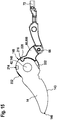
- Figure 12 shows the blocking device 202 in a second state.
- the blocking device 202 is in the second position.
- the cutting elements 12, 14 of the cutting device 10 are in an open position. In the second state, the cutting elements 12, 14 can be moved relative to one another.
- the cutting device 10 is in a state intended at least for manual operation.
- the blocking device 202 In the second position of the blocking device 202, the blocking device 202 enables actuation and / or tool movement of the cutting device 10, in particular of the cutting elements 12, 14 or grip elements 16, 18 relative to one another.
- the charging interface 211 is blocked or closed by the slide switch 204 of the blocking device 202.
- the latching element 206 does not protrude into the recesses 212, 214 of the cutting elements 12, 14.
- At least one of the recesses 212, 214 can also be arranged in at least one structure that is rotationally fixedly connected to one of the cutting elements 12, 14.
- the recess 214 can also be arranged in the lever 80.
- a sealing element (not shown) can be arranged both on the slide switch 204 and on the handle element 18, which enable the charging interface 211 to be sealed.
- the sealing element is in particular arranged between the handle elements 18 and the slide switch 204.
- the at least one sealing element advantageously ensures that the charging interface 211 is sealed in the second position of the blocking device.
- the control unit 52 or other electronic components of the cutting device 10, which are at least in electronic contact with the charging interface 211, can thus advantageously be protected against dust and moisture, in particular when the cutting device is in operation.
- the cutting device 10 also has the force transmission element in the form of the lever 80.
- the lever 80 connects the second cutting element 14 to the second handle element 18.
- the lever 80 has at least one form-locking element for connection to the cutting element 14.
- the second handle element 18 is connected to the lever 80 via at least one further swivel joint 65.
- the grip element 18 and the lever 80 are at least to a limited extent pivotable relative to one another.
- the grip element 18 and the lever 80 pivot around the further swivel joint 65.
- the grip element 18 and the lever 80 are designed to be pivotable relative to one another about the pivot axis 66.
- the pivoting movement is limited at least via the inner contour of the hollow handle element 18.
- the pivoting movement can be limited by form-locking element formed in the grip element 18.
- the grip element 18 is also supported by a spring 68 against the lever 80.
- the grip element 18 is supported at a free end of the lever 80 by means of the spring 68 against the lever 80.
- the cutting device 10 also has a sensor 401.
- the sensor 401 is designed to sense an operating state in which a power assist operation is required.
- the sensor 401 or further sensors can advantageously sense an operating state in which, for the purpose of the operational safety of the cutting device, in particular when an object 17 is arranged between the grip elements 16, 18, an auxiliary operation must be suspended and / or switched off.
- the sensor 401 is preferably a force sensor 40 which is provided to sense a force acting on the second handle element 18, in particular relative to the first handle element 16 and / or relative to the lever 80.
- the force sensor 40 can be provided both to detect an exact force as well as just exceeding a limit force.
- the force sensor 40 is arranged on the second grip element 18 and / or on the force transmission element designed as a lever 80.
- the force sensor 40 is advantageously arranged integrated in the second handle element 18.
- the force sensor 40 is arranged between the lever 80 and the grip element 18.
- the force sensor 40 has at least one spring 68 and a switch 72, in particular a microswitch.
- the spring 68 advantageously supports the lever 80 against an outside 64 of the second grip element 18. If a cutting force F cut acts on the cutting elements 12, 14 when the cutting device 10 is closed, for example for cutting a cut material 11, the second grip element 18 can be moved relative to the force transmission element or to the lever 80 against the spring force F gs of the spring 68 be pivoted in particular.
- the lever 80 and the grip element 18 are arranged so as to be pivotable about the common further swivel joint 65.
- the spring 68 so to speak, couples the grip element 18 to the lever 80 in at least one operating state.
- the lever 80 has a recess and the grip element 18 has an extension, which in particular when connecting two Handle shells of the second handle element 18, forms an axis of rotation 66 about which the lever 80 can rotate or pivot at least to a limited extent.
- the grip element 18 can advantageously be pivoted about the axis of rotation 66 to a limited extent with respect to the lever 80.
- the swiveling limitation ensures at least corresponding positive locking elements on the second handle element 18 and the lever 80.
- the spring 68 can also represent a swivel limitation, in particular the compressed spring 68.
- the second grip element 18 is advantageously supported against the lever 80 at a free end of the lever 80 by means of the spring 68.
- a receiving element 69 is advantageously attached to the lever 80.
- the receiving element 69 advantageously serves as a receptacle, in particular a guide receptacle for the spring 68 and advantageously as a receptacle for the switch 72, in particular as a plug receptacle. If the operating force F user exerted on the grip element 18 for actuating the cutting elements 12, 14 exceeds a spring force F gs , the grip element 18 pivots relative to the lever 80. In the present case, the outside 64 of the grip element 18 approaches the lever 80.
- the force sensor 40 has a switch 72 for detecting this pivoting movement or pivoting force or for detecting at least one threshold value exceeding, a movement of the spring 68 and / or the like.
- the switch 72 is designed as a microswitch, in particular as a break contact or changeover contact.
- the switch 72 has a trigger element designed as a pressure element.
- the pressure element is designed as a pivot element 71, in particular as a pivot lever. It is provided for actuating switch 72.
- the switch 72 advantageously senses a pivoting out or a spacing of the switch 72 from the inside 63 of the second handle element 18. Thus, the switch 72 is activated when the pivoting element 71 is pivoted out.
- the switch 72 is deactivated in a state in which the pivoting element 71 is in contact with the switch 72 and activated in a state in which the pivoting element 71 is pivoted out relative to the switch 72.
- the switch 72 closes when the pivot element 71 is pivoted out in a defined manner.
- the pivot element 71 can be supported directly on the housing of the grip element 18 or on an additional pressure element 81 or the like.
- the pressure element 81 can be designed such that it is provided for selecting a sensitivity of the force sensor 40.
- the pressure element 81 is advantageously part of the force sensor 40, which is advantageously arranged on a further switch 73.
- the other switch serves as a support operation setting element.
- the further switch 73 is advantageously designed to be displaceable transversely to the swivel element 71.
- the further switch 73 can be moved in the direction of the swivel joint 42.
- the further switch 73 is arranged on the side of the second handle element 18 facing the first handle element 16.
- the further switch 73 is thus arranged on the inside 63 of the second handle element 18. An inadvertent actuation of the further switch 73, in particular during a cutting process, can thereby be avoided.
- the further switch 73 is designed as a slide switch.
- the further switch 73 has a pressure element 81 which is wedge-shaped.
- the pressure element 81 is provided to touch the pivot element 71 in all operating states.
- the sensitivity of the force sensor 40 or a threshold value for triggering the switch 72 can be varied by moving the further switch 73 relative to the switch 72 or the swivel element 81. Due to the trigonometric distance relationship of the pressure element 81 to the pivot element 71, in particular via the lever length of the lever 80 within the second handle element 18, the sensitivity of the force sensor 40 can be changed when the further switch 73 is displaced.
- the switch 72 is only activated at a higher operating force F user .
- the switch 72 is activated with a lower operating force F user .
- the sensitivity of the force sensor 40 can thus be set in a cost-effective manner using mechanical means.
- Different activation levels or threshold values can be set for the support operation of the cutting device 10, for example depending on a varying hand force of an operator.
- the further switch 73 advantageously has three latching positions in connection with the switch receptacle, in particular the grip element 18. In this way, three support operating levels can advantageously be defined.
- the design means that there is no need for an additional on / off switch to activate an alternative, purely electronic force or displacement sensor that would require permanent current supply in order to sense a defined threshold value violation. Therefore, the switch 72 and thus the support drive is advantageously activated only when a mechanical Force of the spring 68 is exceeded in the form of a threshold.
- a threshold value as a function of the spring-loaded pivoting movement of the lever 80 within the grip element 18 about the swivel joint 67 is exceeded, so that the switch 72 is triggered.
- a particularly inexpensive and structurally simple force sensor 40 can thereby be provided.
- the driving force transmission element 340 which is operatively connected to the drive unit 20, acts on the lever 80 in the form of the cable 34.
- the lever Upon activation of the drive unit 20 thus the lever is applied with the driving force F and supports the closing movement of the cutting elements 12, 14th
- the lever 80 decouples the driving force F at by a direct application of force to the handle member 18.
- an object 17 between the handle elements 16, 18, the grip elements 16, 18 not to move toward each other can.
- the driving force F on moves the lever 80 within the handle element 18 in the direction of its starting position, the switch 72 is opened, the power support operation ends.
- the force sensor 40 or the lever 80, the spring 68 and the switch 72 decouples a force support operation for compressing the handle elements 16, 18. If an object 17 is arranged between the handle elements 16, 18, the switch 72 is inevitably opened and the drive unit 20 is deactivated, so that there can be no undesired crushing, for example of a limb or the skin of an operator, or damage to the grip elements 16, 18, for example if a branch is arranged between them. In such cases, only the operator F user contributes to crushing the object 17.
- an alternative design of the force sensor 40 would still be conceivable.
- Alternative arrangements of the spring 68, the switch 72 or the further switch 73 for realizing the same functionality are also conceivable.
- a triggering force of the force sensor (s) 40 could be freely defined by software.
- the force sensor 40 can differentiate between different degrees of pressing the switch 72 in or the pivoting of the pivoting element 71, in order to be able to draw conclusions about an exact operator force F user currently present.
- the force sensor 40 is also connected to the control unit 52.
- the control unit 52 is provided for controlling the drive unit 20 as a function of a signal from the force sensor 40.
- the control unit 52 is provided to activate the drive unit 20 when a defined measured value of the force sensor 40 is overwritten.
- the control unit 52 is provided to activate the drive unit 20 when the switch 72 of the force sensor 40 is closed. Furthermore, the control unit 52 is provided to stop the drive unit 20 when the switch 72 of the force sensor 40 is opened.
- a direct connection of the output unit 20 to the energy storage unit 54 via the switch 72 and without the controller 52 is also conceivable.
- the second cutting element 14 is designed as an active cutting element 14 with a cutting edge. It is designed as an exchangeable cutting element 14.
- the second cutting element 14 is connected via at least one positive locking element 216 ( Figure 11 . 12 ) connected to the lever 80 of the cutting device 10, which in turn is connected to the second handle element 18.
- the form-locking elements 216 are provided at least for the transmission of forces in the radial direction about the axis of rotation 420, but can also be designed for the transmission of axial forces F ax in the direction of the axis of rotation 420, on the lever 80 or the cutting element 14.
- a detent 220 is formed on the lever 80, which engages in the form-locking element 216 of the cutting element 14 in the connected state.
- at least one axial guide surface 332 is provided for introducing the cutting element 14 into the cutting element receptacle 400.
- Figure 13 shows a section III-III 'through the cutting device 10 or the cutting element receptacle 400.
- the first and the second cutting element 12, 14 are connected indirectly via a shaft arranged along the axis of rotation 420.
- the shaft forms a swivel joint 42 for the cutting elements 12, 14.
- the shaft is formed at least by a connecting element 421.
- a spacer element 423 is also arranged on the connecting element 421.
- the spacer element 423 serves at least the axial, in the present case also the radial spacing of the connecting element 421 from the cutting elements 12, 14.
- the spacing element 423 can be fixed to the connecting element 421 via a securing element 430.
- the connecting element 421 can also be formed in one piece with the spacing element 423.
- the connecting element 421 is designed as a screw.
- the screw can be loosened and advantageously removed together with the spacing element 423 from the cutting device 10 or the handle housing 44.
- the spacer element 423 is part of a control device 422, which is independent of a clamping force F clamp the connecting element 421 causes a defined contact pressure F on the cutting elements 12, 14 to one another in the direction of the axis of rotation 420.
- the cutting elements 12, 14 have through bores 120, 140 in the axis of rotation 420 through which the connecting element 421 projects.
- the radial surfaces of the through bores 120, 140 form bearing surfaces which are arranged on a corresponding bearing surface of the spacing element 423 or on a sleeve radially encasing the connecting element 421.
- the spacer element 423 defines at least indirectly a minimum distance between two clamping force transmission elements in the direction of the axis of rotation 420, here in the form of the screw head 443 of the screw and in the form of an abutment 425, the abutment being designed as a screw nut, in particular as a screw nut which is received in a rotationally secure manner and with which the Screw is connected.
- These clamping force transmission elements transmit a pretensioning force F clamp of the connecting element 421 at least indirectly to the spacing element 423. Only a definable part of the clamping force F clamp is transmitted to the axial surfaces 121, 141 of the cutting elements 12, 14 by the spacing element 423.
- At least one axial position of the two cutting elements 12, 14 along the axis of rotation or a frictional force between the cutting elements 12, 14, which occurs when these are pivoted relative to one another, can be determined independently of a tightening torque of the connecting element 423 or independently of a further influencing variable ,
- a length extension I of the spacer element 423 in the direction of the axis of rotation 420 allows a relative movement of the cutting elements 12, 14, in particular a pivoting movement of the cutting elements 12, 14 with respect to one another. They advantageously corresponds to at least the sum of the width dimensions b 1, b 2 of the two cutting elements 12, 14 along the rotational axis 420.
- control device can have an elastic element 424 that applies a defined axial force or clamping force F clamp along the axis of rotation 420 to the cutting elements 12, 14.
- the elastic element 424 is designed as a spring, in particular as a compression spring, particularly preferably as a corrugated spring.
- the elastic element 424 is arranged indirectly between an axial surface 122 of the first cutting element 12 and a radial shoulder 426 of the spacing element 423.
- the elastic element is arranged between the axial surface 122 of the first cutting element 12 and a locking ring 427.
- the locking ring 427 is supported on the shoulder 426 of the spacer element 423. Furthermore, the locking ring 427 is also supported on the handle housing 44.
- the axial force F corresponds ax and acts as a pressing force F on or as pressure or normal force between the two cutting elements 12, 14.
- the elastic member 424 a friction force between the cutting elements 12, 14 on.
- a basic operating force for closing the cutting device 10 can be determined at least in part.
- a basic distance between the cutting elements 12, 14 can thereby be set. Regardless of the production width - within a tolerance band - of the cutting elements 12, 14, the contact pressure F on the cutting elements 12, 14 relative to one another remains almost constant due to the spring constant of the elastic element 424. Further tolerances of the cutting element receptacle 400 can also be compensated for.
- a sheet of paper as well as a branch can thus advantageously be cut by the cutting device 10, since the cutting gap can adapt to the requirement given by the material to be cut 11.
- An exchange of the second cutting element 14 is possible without readjusting the clamping force or a tightening torque of the screw or a variation of intermediate elements. Regardless of the clamping force or the tightening torque of the connecting element 423 or the screw, the contact pressure F an between the cutting elements 12, 14 remains almost constant.
- the wave spring advantageously has an outside diameter in the range of 20 mm and an inside diameter in the range of 15 mm.
- a free axial length of the wave spring is advantageously less than 5 mm, in particular 3.25 mm.
- the clamping force of the corrugated spring is advantageously 15 to 25 N, with a compressed length of 1.1 to 1.5 mm.
- the connecting element 423 is released and, in particular, the connecting and spacing element 421, 423 is completely removed, the securing ring 427 is axially supported on the handle housing 44.
- the securing ring 427 is axially supported on the handle housing 44.
- at least a reduced axial force F ax of the spring or a contact pressure F on at least the first cutting element 12 is maintained.
- the second cutting element 14 to be exchanged can at least be positioned even without a connecting element 421 and / or is secured against unintentional falling out of the cutting device 10.
- the first, in particular stationary, cutting element 12 is also designed to be displaceable in the transverse direction, that is to say displaceable in the direction of the axis of rotation 420. It is secured in the direction of rotation around the axis of rotation by positive locking elements. These are supported on corresponding positive locking elements in the first grip element 16.
- the corresponding interlocking elements are connecting elements for connecting the handle shells of the first handle element 16.
- the elastic element 424 also serves as an overload protection element of the cutting device 10. It prevents plastic deformation of the cutting elements 12, 14 during operation of the cutting device 10.
- the elastic element 424 sets a threshold value F ax , from which the cutting element 10 may gap.
- F ax the threshold value
- the elastic element yields at least up to the axial stop of the second cutting element 14 on a stop element 442 and thus enables at least slight axial displacement and / or tilting within the first grip element 16 or along the axis of rotation 420
- Elastic behavior and the desired gaping when a defined threshold value is exceeded can be set via the spring force of the elastic element 424 and the arrangement of the control device 422.
- the control device 422 comprises at least the connecting element 421, the spacing element 423, the locking ring 427 and the elastic element 424.
- the abutment 425 of the connecting element 421 in the form of the screw nut is firmly accommodated in the handle housing 44 of the cutting device 10. About one hexagonal form-locking element 428, it is held against rotation.
- a cover 429 which is connected to the handle housing 44, axially secures the screw nut so that it is positioned on the cutting device 10 even when the connecting element 421 is removed.
- a sliding element 440 in the form of a sliding ring or a sliding disk is also arranged between the handle housing 44 and the lever 80. At least one fixing element 441 is connected to the handle housing 44 in a rotationally fixed manner. Furthermore, the sliding element 440 is also arranged between the spacing element 423 and the abutment 425 designed as a screw nut.
- the abutment is thus axially secured between the sliding element 440 and the cover 429, in particular when the connecting element 421 is removed. Furthermore, the sliding element 440 decouples a potential rotary movement of the spacer element 423 from the abutment 425.
- the control device 422 can be secured at least indirectly with the handle housing 44 and / or the stationary first cutting element 12 at one or more points, so that the relative movement of the lever 80 or the first cutting element 12 does not lead to an unwanted loosening of the connecting element 421.
- the sliding element, the abutment 425 and / or the spacing element 423 are accommodated on the handle housing 44 in a manner secured against rotation.
- a thickness of the first cutting element 12 is advantageously 4 mm.
- a thickness of the second cutting element 14 is advantageously 3.5 mm at its thickest point.
- a thickness of the lever 80 is advantageously 3.5 mm.
- Figure 14 shows a cutting element, which is designed as the second cutting element 14 in a plan view and a side view.
- the second cutting element 14 has a blade 143.
- the second cutting element 14 is a replaceable cutting element for the cutting device 10.
- the second cutting element 14 has a tip 146 and an end 148 opposite the tip 146. In the area of the end 148, the second cutting element 14 has a recess 214.
- the recess 214 serves as a receptacle for a locking element 210 of the blocking device 202 of the cutting device 10 for blocking a movement of the cutting elements 12, 14 relative to one another.
- the second cutting element 14 has the form-locking element 216, which as Counter-locking recess for the locking lug 220 of the lever 80 of the cutting device 10 is formed.
- the form-locking element 216 serves to transmit radial forces of the grip element 18, in particular via the lever 80, around the swivel joint 42 of the cutting device 10.
- the end 148 of the second cutting element 14 is also at least partially rounded.
- the second cutting element 14 has an insertion aid 144 in the form of an inclined surface.
- the insertion aid 144 is chamfered with respect to a sectional area plane of the second cutting element 14 formed by the sectional area 145, but can also be round, in particular spherical.
- the insertion aid 144 extends essentially from the center of the receptacle 142 in the radial direction to the end 148 of the second cutting element 14.
- a thickness of the second cutting element 14 decreases in the region of the insertion aid 144 in the direction of the end 148. The thickness decreases from around 3.5 mm to 2.7 mm.
- a leg length of the inclined surface is advantageously 9 mm.
- the angle ⁇ of the inclined surface is advantageously less than 30 °, in particular less than 15 ° and very particularly preferably around 5 °.
- a contact surface 149 extends between the insertion aid 144 and the blade 143.
- the contact surface 149 is provided for a positive connection with the lever 80. It is flat and oriented normal to the direction of the recess 142 or normal to the direction of an axis of rotation 420 of the secateurs 10.
- the opposite cutting surface 145 is designed to slide along the first cutting element 12. It swivels smoothly along the first cutting element 12 about the axis of rotation 420 or the swivel joint 42.
- An actuation of the cutting device is preferably only possible when the blocking device is in the second position.
- a loading process of the cutting device is preferably not provided in this second position.
- the cutting device 10 is constantly in an operating mode. As soon as the switch 72 is closed, the control unit 52 activates the drive motor 20.
- the cutting device 10 in particular additionally has an operating switch by means of which the cutting device 10 can be activated and deactivated.
- the cutting device 10 itself can be activated, for example, by a defined closing and / or opening sequence of the cutting device 10. Deactivation would be conceivable, for example, depending on the time.
- step 1180 If an operator wishes to carry out a cutting operation during operation, such as cutting a branch, for example, he has to position the material to be cut 11 between the cutting elements 12, 14 of the cutting device 10.
- the cutting elements 12, 14 can then be closed, in particular as in conventional garden shears, by compressing the grip elements 16, 18 relative to one another.
- the handle elements 16, 18 are manually compressed by an operator in a step 1180. If the spring force of the force sensor 40 is not exceeded, the switch 72 does not output a signal.
- the control unit 52 monitors a signal from the force sensor 40 or switch 72. The control unit 52 thus monitors a force required for a cutting process. The control unit 52 checks whether the switch 72 of the force sensor 40 is open or closed.
- step 1200 is repeated in the following branch 1220.
- the handle elements 16, 18 are pivoted against one another manually by an operator.
- the cable 34 is wound on the cable winch 32 by means of the reset unit 31 or the spring element 36. Since a force acts on the clutch unit 22 from an output side, the clutch unit 22 is in an open state. The cable winch 32 can therefore be rotated without resistance from the gear unit 38 and the drive unit 20. The cable 34 is held in tension by the spring element 36 in this state.
- the grip elements 16, 18 are pressed apart by means of the opening spring 50 and the cutting device 10 is opened.
- the cable 34 is unwound from the cable winch 32 against the spring force of the spring element 36.
- the cutting device 10 can be used in a manual mode, the drive unit 20 remaining deactivated even when a force defined by the force sensor 40 is exceeded. There is no activation of the drive unit 20, whereby the clutch unit 22 also remains open.
- the cutting device 10 is used in an assisted mode.
- a change from a manual mode to a supported mode always takes place during a cutting process.
- the handle elements 16, 18 are pivoted against one another manually by an operator. If a hard clippings 11 are cut, the handle elements 16, 18 must be pressed against one another by a user with high force. If a force is applied so high that the switch 72 closes a spring force F gs when overcome, this is sensed by the control unit 52. The control unit 52 then activates the drive unit 20.
- the drive unit 20 is activated via the control unit 52 in a step 1240.
- the drive unit 20 is accordingly activated when a defined operator force is exceeded in a closing mechanism of the cutting device 10.
- the drive unit 20 then drives the inner rotary element 46 of the clutch unit 22 via the gear unit 38.
- the drive unit 20 is driven in the drive direction 41.
- the clutch unit 22 is closed and drives the cable winch 32.
- the rope 34 is wound on the winch 32.
- the handle elements 16, 18 are now compressed or contracted by a drive force F as .
- the drive unit 20 applies an additional force to the cutting elements 12, 14 during a partially manual movement.
- the driving force F as acts on the cable 34 via the cable winch 32.
- the driving force F as acts here via the cable 34 on the lever 80. If the operating force F user is still greater than a force defined by the force sensor 40, which is required to close the switch 72, the manual movement by the driving force is F an continues to be supported. If, on the other hand, the operator force F user diminishes in such a way that the switch 72 opens, the drive unit 20 stops in a step 1260. The drive unit 20 can also be stopped in step 1260 if the two handle elements 16, 18 are closed or over the Touch spacing element 630 or an object 17 is arranged between the grip elements 16, 18, whereby a force defined by the force sensor 40, which is required to close the switch 72, is also undershot.
- the operating force F user can no longer act on the force sensor 40, since the driving force F as acts on the lever 80 via the cable 34 and moves it into its starting position in which the switch 72 is open.
- the drive unit 20 is then briefly driven in the opposite drive direction 410 in a step 1280 in order to open the clutch unit 22.
- the braking element 28 brakes the cage 26, the clamping bodies 24 no longer clamp the outer with the inner rotating element 46, 48.
- This reversal of direction of the drive unit 20 or the drive of the drive unit 20 in the counter-drive direction 410 can fail briefly, for example less than 100 milliseconds amount, in particular 40 milliseconds.
- the drive unit 20 is deactivated in a step 1300. After the drive unit 20 has been deactivated, the method can be started again.
- the coupling unit 22 can also decouple the drive unit 20 automatically if there is no rotational movement.
- the cutting device 10 can in principle also be at least partially opened by the opening spring 50 and the cable winch 32 can be partially rotated via the cable 34 against a drive direction 41 of the drive unit 20.
- the inner rotary element 46 can likewise be rotated relative to the outer rotary element 48 of the clutch unit 22 and the clutch unit 22 can be opened in this way.
- another method for opening the clutch unit 22 would also be conceivable.
Landscapes
- Life Sciences & Earth Sciences (AREA)
- Biodiversity & Conservation Biology (AREA)
- Ecology (AREA)
- Forests & Forestry (AREA)
- Environmental Sciences (AREA)
- Harvester Elements (AREA)
- Scissors And Nippers (AREA)
Priority Applications (1)
| Application Number | Priority Date | Filing Date | Title |
|---|---|---|---|
| EP25156577.6A EP4585033A3 (fr) | 2016-06-30 | 2017-05-18 | Dispositif de coupe |
Applications Claiming Priority (2)
| Application Number | Priority Date | Filing Date | Title |
|---|---|---|---|
| DE102016211975.3A DE102016211975A1 (de) | 2016-06-30 | 2016-06-30 | Schneidvorrichtung |
| EP17171652.5A EP3262923B1 (fr) | 2016-06-30 | 2017-05-18 | Dispositif de coupe |
Related Parent Applications (2)
| Application Number | Title | Priority Date | Filing Date |
|---|---|---|---|
| EP17171652.5A Division EP3262923B1 (fr) | 2016-06-30 | 2017-05-18 | Dispositif de coupe |
| EP17171652.5A Division-Into EP3262923B1 (fr) | 2016-06-30 | 2017-05-18 | Dispositif de coupe |
Related Child Applications (2)
| Application Number | Title | Priority Date | Filing Date |
|---|---|---|---|
| EP25156577.6A Division-Into EP4585033A3 (fr) | 2016-06-30 | 2017-05-18 | Dispositif de coupe |
| EP25156577.6A Division EP4585033A3 (fr) | 2016-06-30 | 2017-05-18 | Dispositif de coupe |
Publications (3)
| Publication Number | Publication Date |
|---|---|
| EP3583839A2 true EP3583839A2 (fr) | 2019-12-25 |
| EP3583839A3 EP3583839A3 (fr) | 2020-05-20 |
| EP3583839B1 EP3583839B1 (fr) | 2025-04-16 |
Family
ID=58745079
Family Applications (3)
| Application Number | Title | Priority Date | Filing Date |
|---|---|---|---|
| EP25156577.6A Pending EP4585033A3 (fr) | 2016-06-30 | 2017-05-18 | Dispositif de coupe |
| EP17171652.5A Active EP3262923B1 (fr) | 2016-06-30 | 2017-05-18 | Dispositif de coupe |
| EP19184934.8A Active EP3583839B1 (fr) | 2016-06-30 | 2017-05-18 | Dispositif de coupe |
Family Applications Before (2)
| Application Number | Title | Priority Date | Filing Date |
|---|---|---|---|
| EP25156577.6A Pending EP4585033A3 (fr) | 2016-06-30 | 2017-05-18 | Dispositif de coupe |
| EP17171652.5A Active EP3262923B1 (fr) | 2016-06-30 | 2017-05-18 | Dispositif de coupe |
Country Status (3)
| Country | Link |
|---|---|
| EP (3) | EP4585033A3 (fr) |
| CN (2) | CN114402830A (fr) |
| DE (1) | DE102016211975A1 (fr) |
Families Citing this family (14)
| Publication number | Priority date | Publication date | Assignee | Title |
|---|---|---|---|---|
| US10172292B2 (en) | 2016-10-17 | 2019-01-08 | Robert Bosch Gmbh | Cutting device |
| DE102018201159A1 (de) * | 2018-01-25 | 2019-07-25 | Robert Bosch Gmbh | Handwerkzeugmaschine |
| CN109197212B (zh) * | 2018-11-15 | 2021-04-20 | 浙江东立电器有限公司 | 一种防剪手节能型农用修枝剪 |
| DE102018251740A1 (de) * | 2018-12-27 | 2020-07-02 | Robert Bosch Gmbh | Schneidvorrichtung |
| DE102018251743A1 (de) | 2018-12-27 | 2020-07-02 | Robert Bosch Gmbh | Schneidvorrichtung |
| EP3858133A1 (fr) * | 2020-01-29 | 2021-08-04 | Husqvarna Ab | Outil de découpe |
| EP3858560A1 (fr) * | 2020-01-29 | 2021-08-04 | Husqvarna Ab | Outil de découpe |
| CN116456822B (zh) * | 2020-11-20 | 2024-04-09 | 胡斯华纳有限公司 | 切割工具 |
| US11212965B1 (en) | 2021-01-28 | 2022-01-04 | Lester Duane Hames | Tool for deep selective pruning of branches and vines |
| SE546362C2 (en) * | 2022-06-13 | 2024-10-15 | Komatsu Forest Ab | Control method for tree shears measuring the cutting force or speed and tree shears per se |
| SE546521C2 (en) * | 2022-06-13 | 2024-11-19 | Komatsu Forest Ab | Method for cutting tree and tree shears for carrying out the method |
| CN115885711A (zh) * | 2022-11-02 | 2023-04-04 | 德明通讯(上海)股份有限公司 | 一种智能修枝剪 |
| WO2025088592A2 (fr) * | 2023-10-26 | 2025-05-01 | Inesc Tec - Instituto De Engenharia De Sistemas E Computadores, Tecnologia E Ciência | Appareil de surveillance complémentaire pour un outil de coupe, outil de coupe respectif, système et procédé de surveillance |
| EP4653156B1 (fr) * | 2024-05-22 | 2026-04-29 | Husqvarna AB | Outil de coupe |
Family Cites Families (28)
| Publication number | Priority date | Publication date | Assignee | Title |
|---|---|---|---|---|
| US1587718A (en) * | 1924-07-03 | 1926-06-08 | Gentile Pasquale | Automatic scissors |
| DE3426577A1 (de) * | 1983-09-09 | 1985-03-28 | Gardena Kress + Kastner Gmbh, 7900 Ulm | Schere, insbesondere gartenschere |
| CN2129670Y (zh) * | 1992-08-01 | 1993-04-14 | 柯于文 | 多功能钳 |
| DE29518836U1 (de) * | 1995-11-28 | 1996-01-18 | Hauck, Stefan, Dipl.-Ing. (FH), 86633 Neuburg | Elektromechanisch angetriebene Schere zum Schneiden von Papier, Karton, Textilien oder ähnlichen Materialien |
| JPH10117592A (ja) * | 1996-10-18 | 1998-05-12 | Arusu Corp Kk | 刃体の開きを制限するストッパー機構を備えた鋏 |
| US6860018B2 (en) * | 1998-07-22 | 2005-03-01 | Wolf-Garten Gmbh & Co. Kg | Shear-locking device |
| DE20205106U1 (de) * | 2001-04-24 | 2002-06-27 | Meier, Johann, Oberägeri | Garten- oder Baumschere |
| GB2404613A (en) * | 2003-07-14 | 2005-02-09 | David Jarman | A vegetation pruning device |
| TWM253467U (en) * | 2003-12-08 | 2004-12-21 | Bi-Ju Lin | Electric scissors device |
| EP1827772A1 (fr) * | 2004-10-18 | 2007-09-05 | Koninklijke Philips Electronics N.V. | Ciseaux et dispositifs d'entrainement pour ciseaux |
| JP4941910B2 (ja) * | 2006-08-18 | 2012-05-30 | 広島県 | 鋏型手動利器及びそのグリップアタッチメント |
| ATE514332T1 (de) * | 2007-04-19 | 2011-07-15 | Black & Decker Inc | Griffverriegelungmechanismus |
| DE102010016296B4 (de) * | 2010-04-01 | 2012-05-03 | AR&T, Applied Robot & Technologies UG (haftungsbeschränkt) | Hilfskraftbetätigte Handschere und Verfahren zu deren Betrieb |
| CO6360206A1 (es) * | 2010-07-30 | 2012-01-20 | Pontifica Universidad Javerian | Herramienta ergonomica para el corte de flores y frutos |
| CN201894087U (zh) * | 2010-08-19 | 2011-07-13 | 杭州埃法花园设备有限公司 | 一种园艺剪刀 |
| DE202011000116U1 (de) * | 2011-01-17 | 2011-04-21 | JIIN HAUR INDUSTRIAL CO., LTD., Lu Kang | Griffanordnung einer Gartenschere |
| CN102310222B (zh) * | 2011-09-06 | 2013-08-21 | 南京德朔实业有限公司 | 可安全换刀片的电动工具 |
| JP6001427B2 (ja) * | 2011-12-21 | 2016-10-05 | スターテング工業株式会社 | 電動アシスト機能付きはさみ |
| CN203031030U (zh) * | 2012-12-06 | 2013-07-03 | 河北师范大学 | 一种防夹手的剪刀 |
| JP6226420B2 (ja) * | 2013-09-20 | 2017-11-08 | スターテング工業株式会社 | 電動アシスト機能付きはさみ |
| CN103949991A (zh) * | 2014-03-25 | 2014-07-30 | 北京航天发射技术研究所 | 一种可任意角度使用的钳子 |
| US20150313089A1 (en) * | 2014-04-30 | 2015-11-05 | Remo Francesco CECCHI | Cutting system |
| CN105075688A (zh) * | 2014-05-21 | 2015-11-25 | 新昌县康泓机械科技有限公司 | 一种智能判断闭合助力的割具 |
| CN204431174U (zh) * | 2015-01-26 | 2015-07-01 | 中国海洋石油总公司 | 一种推靠缸拆装工具 |
| CN204579252U (zh) * | 2015-02-09 | 2015-08-26 | 李佑奇 | 一种新型园林剪刀 |
| DE202015100971U1 (de) * | 2015-02-27 | 2015-03-18 | Jiin Haur Industrial Co., Ltd. | Gartenschere |
| DE102015206959A1 (de) * | 2015-04-17 | 2016-10-20 | Robert Bosch Gmbh | Schneidevorrichtung |
| CN204868931U (zh) * | 2015-07-24 | 2015-12-16 | 徐伟明 | 一种厨房剪刀 |
-
2016
- 2016-06-30 DE DE102016211975.3A patent/DE102016211975A1/de active Pending
-
2017
- 2017-05-18 EP EP25156577.6A patent/EP4585033A3/fr active Pending
- 2017-05-18 EP EP17171652.5A patent/EP3262923B1/fr active Active
- 2017-05-18 EP EP19184934.8A patent/EP3583839B1/fr active Active
- 2017-06-30 CN CN202210052635.0A patent/CN114402830A/zh active Pending
- 2017-06-30 CN CN201710523443.2A patent/CN107548767B/zh active Active
Also Published As
| Publication number | Publication date |
|---|---|
| CN107548767A (zh) | 2018-01-09 |
| EP3583839B1 (fr) | 2025-04-16 |
| DE102016211975A1 (de) | 2018-01-04 |
| CN114402830A (zh) | 2022-04-29 |
| EP3262923A3 (fr) | 2018-03-28 |
| CN107548767B (zh) | 2022-01-04 |
| EP4585033A2 (fr) | 2025-07-16 |
| EP3262923B1 (fr) | 2019-09-25 |
| EP3262923A2 (fr) | 2018-01-03 |
| EP4585033A3 (fr) | 2025-08-27 |
| EP3583839A3 (fr) | 2020-05-20 |
Similar Documents
| Publication | Publication Date | Title |
|---|---|---|
| EP3262923B1 (fr) | Dispositif de coupe | |
| EP3081075B2 (fr) | Dispositif de coupe | |
| US11672208B2 (en) | Cutting device | |
| DE102016211974B4 (de) | Schneidvorrichtung | |
| EP1519813A2 (fr) | Appareil de pressage electrohydraulique et procede pour faire fonctionner un tel appareil | |
| EP1704021A2 (fr) | Outil de serrage et/ou d'ecartement muni d'un mecanisme pas a pas et de moyens d'actionnement a ressort pour deplacer les deux machoires l'une par rapport a l'autre de facon continue | |
| DE202011052137U1 (de) | Kraftwerkzeug mit einer automatischen Drehzahlregelungsvorrichtung | |
| DE102016211973A1 (de) | Blockiervorrichtung | |
| EP2371462A2 (fr) | Appareil de nettoyage manuel pour le nettoyage de conduites | |
| WO2018234311A2 (fr) | Bride de fixation et procédé de fonctionnement d'une bride de fixation | |
| EP3673725A1 (fr) | Dispositif de coupe | |
| DE102018251743A1 (de) | Schneidvorrichtung | |
| EP3516947B1 (fr) | Dispositif de coupe | |
| DE3323150C2 (fr) | ||
| DE102016211976A1 (de) | Schneidvorrichtung | |
| EP3552478B1 (fr) | Machine-outil portative | |
| DE102016211978A1 (de) | Schneidelement für eine Gartenschere | |
| DE102016211972A1 (de) | Kontrollvorrichtung | |
| DE3800647C2 (de) | Überlastschutzvorrichtung für einen Drehantrieb, insbesondere einen Drehantrieb für Flugzeug-Landeklappen | |
| EP4480650B1 (fr) | Coupe-bordures, ensemble d'accouplement associé et utilisation associée | |
| EP2621685B1 (fr) | Outil à main comprenant un boîtier conçu comme poignée | |
| DE102009015822B3 (de) | Heckenschere | |
| DE19720699A1 (de) | Drehmomentgeschaltete Kupplung |
Legal Events
| Date | Code | Title | Description |
|---|---|---|---|
| PUAI | Public reference made under article 153(3) epc to a published international application that has entered the european phase |
Free format text: ORIGINAL CODE: 0009012 |
|
| STAA | Information on the status of an ep patent application or granted ep patent |
Free format text: STATUS: THE APPLICATION HAS BEEN PUBLISHED |
|
| AC | Divisional application: reference to earlier application |
Ref document number: 3262923 Country of ref document: EP Kind code of ref document: P |
|
| AK | Designated contracting states |
Kind code of ref document: A2 Designated state(s): AL AT BE BG CH CY CZ DE DK EE ES FI FR GB GR HR HU IE IS IT LI LT LU LV MC MK MT NL NO PL PT RO RS SE SI SK SM TR |
|
| PUAL | Search report despatched |
Free format text: ORIGINAL CODE: 0009013 |
|
| RAP1 | Party data changed (applicant data changed or rights of an application transferred) |
Owner name: ROBERT BOSCH GMBH |
|
| AK | Designated contracting states |
Kind code of ref document: A3 Designated state(s): AL AT BE BG CH CY CZ DE DK EE ES FI FR GB GR HR HU IE IS IT LI LT LU LV MC MK MT NL NO PL PT RO RS SE SI SK SM TR |
|
| RIC1 | Information provided on ipc code assigned before grant |
Ipc: A01G 3/037 20060101AFI20200414BHEP |
|
| STAA | Information on the status of an ep patent application or granted ep patent |
Free format text: STATUS: REQUEST FOR EXAMINATION WAS MADE |
|
| 17P | Request for examination filed |
Effective date: 20201120 |
|
| RBV | Designated contracting states (corrected) |
Designated state(s): AL AT BE BG CH CY CZ DE DK EE ES FI FR GB GR HR HU IE IS IT LI LT LU LV MC MK MT NL NO PL PT RO RS SE SI SK SM TR |
|
| P01 | Opt-out of the competence of the unified patent court (upc) registered |
Effective date: 20230509 |
|
| STAA | Information on the status of an ep patent application or granted ep patent |
Free format text: STATUS: EXAMINATION IS IN PROGRESS |
|
| 17Q | First examination report despatched |
Effective date: 20240104 |
|
| GRAP | Despatch of communication of intention to grant a patent |
Free format text: ORIGINAL CODE: EPIDOSNIGR1 |
|
| STAA | Information on the status of an ep patent application or granted ep patent |
Free format text: STATUS: GRANT OF PATENT IS INTENDED |
|
| INTG | Intention to grant announced |
Effective date: 20241125 |
|
| GRAS | Grant fee paid |
Free format text: ORIGINAL CODE: EPIDOSNIGR3 |
|
| GRAA | (expected) grant |
Free format text: ORIGINAL CODE: 0009210 |
|
| STAA | Information on the status of an ep patent application or granted ep patent |
Free format text: STATUS: THE PATENT HAS BEEN GRANTED |
|
| AC | Divisional application: reference to earlier application |
Ref document number: 3262923 Country of ref document: EP Kind code of ref document: P |
|
| AK | Designated contracting states |
Kind code of ref document: B1 Designated state(s): AL AT BE BG CH CY CZ DE DK EE ES FI FR GB GR HR HU IE IS IT LI LT LU LV MC MK MT NL NO PL PT RO RS SE SI SK SM TR |
|
| REG | Reference to a national code |
Ref country code: GB Ref legal event code: FG4D Free format text: NOT ENGLISH |
|
| REG | Reference to a national code |
Ref country code: CH Ref legal event code: EP |
|
| REG | Reference to a national code |
Ref country code: IE Ref legal event code: FG4D Free format text: LANGUAGE OF EP DOCUMENT: GERMAN |
|
| REG | Reference to a national code |
Ref country code: DE Ref legal event code: R096 Ref document number: 502017016805 Country of ref document: DE |
|
| REG | Reference to a national code |
Ref country code: NL Ref legal event code: MP Effective date: 20250416 |
|
| PG25 | Lapsed in a contracting state [announced via postgrant information from national office to epo] |
Ref country code: NL Free format text: LAPSE BECAUSE OF FAILURE TO SUBMIT A TRANSLATION OF THE DESCRIPTION OR TO PAY THE FEE WITHIN THE PRESCRIBED TIME-LIMIT Effective date: 20250416 |
|
| PG25 | Lapsed in a contracting state [announced via postgrant information from national office to epo] |
Ref country code: ES Free format text: LAPSE BECAUSE OF FAILURE TO SUBMIT A TRANSLATION OF THE DESCRIPTION OR TO PAY THE FEE WITHIN THE PRESCRIBED TIME-LIMIT Effective date: 20250416 Ref country code: FI Free format text: LAPSE BECAUSE OF FAILURE TO SUBMIT A TRANSLATION OF THE DESCRIPTION OR TO PAY THE FEE WITHIN THE PRESCRIBED TIME-LIMIT Effective date: 20250416 Ref country code: PT Free format text: LAPSE BECAUSE OF FAILURE TO SUBMIT A TRANSLATION OF THE DESCRIPTION OR TO PAY THE FEE WITHIN THE PRESCRIBED TIME-LIMIT Effective date: 20250818 |
|
| PGFP | Annual fee paid to national office [announced via postgrant information from national office to epo] |
Ref country code: DE Payment date: 20250716 Year of fee payment: 9 |
|
| REG | Reference to a national code |
Ref country code: LT Ref legal event code: MG9D |
|
| PG25 | Lapsed in a contracting state [announced via postgrant information from national office to epo] |
Ref country code: NO Free format text: LAPSE BECAUSE OF FAILURE TO SUBMIT A TRANSLATION OF THE DESCRIPTION OR TO PAY THE FEE WITHIN THE PRESCRIBED TIME-LIMIT Effective date: 20250716 Ref country code: GR Free format text: LAPSE BECAUSE OF FAILURE TO SUBMIT A TRANSLATION OF THE DESCRIPTION OR TO PAY THE FEE WITHIN THE PRESCRIBED TIME-LIMIT Effective date: 20250717 |
|
| PG25 | Lapsed in a contracting state [announced via postgrant information from national office to epo] |
Ref country code: PL Free format text: LAPSE BECAUSE OF FAILURE TO SUBMIT A TRANSLATION OF THE DESCRIPTION OR TO PAY THE FEE WITHIN THE PRESCRIBED TIME-LIMIT Effective date: 20250416 |
|
| PG25 | Lapsed in a contracting state [announced via postgrant information from national office to epo] |
Ref country code: BG Free format text: LAPSE BECAUSE OF FAILURE TO SUBMIT A TRANSLATION OF THE DESCRIPTION OR TO PAY THE FEE WITHIN THE PRESCRIBED TIME-LIMIT Effective date: 20250416 |
|
| PGFP | Annual fee paid to national office [announced via postgrant information from national office to epo] |
Ref country code: GB Payment date: 20250717 Year of fee payment: 9 |
|
| PG25 | Lapsed in a contracting state [announced via postgrant information from national office to epo] |
Ref country code: HR Free format text: LAPSE BECAUSE OF FAILURE TO SUBMIT A TRANSLATION OF THE DESCRIPTION OR TO PAY THE FEE WITHIN THE PRESCRIBED TIME-LIMIT Effective date: 20250416 |
|
| PGFP | Annual fee paid to national office [announced via postgrant information from national office to epo] |
Ref country code: FR Payment date: 20250718 Year of fee payment: 9 |
|
| PG25 | Lapsed in a contracting state [announced via postgrant information from national office to epo] |
Ref country code: RS Free format text: LAPSE BECAUSE OF FAILURE TO SUBMIT A TRANSLATION OF THE DESCRIPTION OR TO PAY THE FEE WITHIN THE PRESCRIBED TIME-LIMIT Effective date: 20250716 |
|
| PG25 | Lapsed in a contracting state [announced via postgrant information from national office to epo] |
Ref country code: IS Free format text: LAPSE BECAUSE OF FAILURE TO SUBMIT A TRANSLATION OF THE DESCRIPTION OR TO PAY THE FEE WITHIN THE PRESCRIBED TIME-LIMIT Effective date: 20250816 |
|
| PG25 | Lapsed in a contracting state [announced via postgrant information from national office to epo] |
Ref country code: LV Free format text: LAPSE BECAUSE OF FAILURE TO SUBMIT A TRANSLATION OF THE DESCRIPTION OR TO PAY THE FEE WITHIN THE PRESCRIBED TIME-LIMIT Effective date: 20250416 |
|
| REG | Reference to a national code |
Ref country code: CH Ref legal event code: H13 Free format text: ST27 STATUS EVENT CODE: U-0-0-H10-H13 (AS PROVIDED BY THE NATIONAL OFFICE) Effective date: 20251223 |
|
| PG25 | Lapsed in a contracting state [announced via postgrant information from national office to epo] |
Ref country code: SM Free format text: LAPSE BECAUSE OF FAILURE TO SUBMIT A TRANSLATION OF THE DESCRIPTION OR TO PAY THE FEE WITHIN THE PRESCRIBED TIME-LIMIT Effective date: 20250416 Ref country code: DK Free format text: LAPSE BECAUSE OF FAILURE TO SUBMIT A TRANSLATION OF THE DESCRIPTION OR TO PAY THE FEE WITHIN THE PRESCRIBED TIME-LIMIT Effective date: 20250416 |
|
| PG25 | Lapsed in a contracting state [announced via postgrant information from national office to epo] |
Ref country code: LU Free format text: LAPSE BECAUSE OF NON-PAYMENT OF DUE FEES Effective date: 20250518 |
|
| PG25 | Lapsed in a contracting state [announced via postgrant information from national office to epo] |
Ref country code: CH Free format text: LAPSE BECAUSE OF NON-PAYMENT OF DUE FEES Effective date: 20250531 |
|
| REG | Reference to a national code |
Ref country code: DE Ref legal event code: R097 Ref document number: 502017016805 Country of ref document: DE |
|
| PG25 | Lapsed in a contracting state [announced via postgrant information from national office to epo] |
Ref country code: CZ Free format text: LAPSE BECAUSE OF FAILURE TO SUBMIT A TRANSLATION OF THE DESCRIPTION OR TO PAY THE FEE WITHIN THE PRESCRIBED TIME-LIMIT Effective date: 20250416 |
|
| PG25 | Lapsed in a contracting state [announced via postgrant information from national office to epo] |
Ref country code: EE Free format text: LAPSE BECAUSE OF FAILURE TO SUBMIT A TRANSLATION OF THE DESCRIPTION OR TO PAY THE FEE WITHIN THE PRESCRIBED TIME-LIMIT Effective date: 20250416 |
|
| PG25 | Lapsed in a contracting state [announced via postgrant information from national office to epo] |
Ref country code: RO Free format text: LAPSE BECAUSE OF FAILURE TO SUBMIT A TRANSLATION OF THE DESCRIPTION OR TO PAY THE FEE WITHIN THE PRESCRIBED TIME-LIMIT Effective date: 20250416 Ref country code: SK Free format text: LAPSE BECAUSE OF FAILURE TO SUBMIT A TRANSLATION OF THE DESCRIPTION OR TO PAY THE FEE WITHIN THE PRESCRIBED TIME-LIMIT Effective date: 20250416 |
|
| PG25 | Lapsed in a contracting state [announced via postgrant information from national office to epo] |
Ref country code: IT Free format text: LAPSE BECAUSE OF FAILURE TO SUBMIT A TRANSLATION OF THE DESCRIPTION OR TO PAY THE FEE WITHIN THE PRESCRIBED TIME-LIMIT Effective date: 20250416 |
|
| REG | Reference to a national code |
Ref country code: BE Ref legal event code: MM Effective date: 20250531 |
|
| PG25 | Lapsed in a contracting state [announced via postgrant information from national office to epo] |
Ref country code: MC Free format text: LAPSE BECAUSE OF FAILURE TO SUBMIT A TRANSLATION OF THE DESCRIPTION OR TO PAY THE FEE WITHIN THE PRESCRIBED TIME-LIMIT Effective date: 20250416 |
|
| PLBE | No opposition filed within time limit |
Free format text: ORIGINAL CODE: 0009261 |
|
| STAA | Information on the status of an ep patent application or granted ep patent |
Free format text: STATUS: NO OPPOSITION FILED WITHIN TIME LIMIT |
|
| REG | Reference to a national code |
Ref country code: CH Ref legal event code: L10 Free format text: ST27 STATUS EVENT CODE: U-0-0-L10-L00 (AS PROVIDED BY THE NATIONAL OFFICE) Effective date: 20260225 |
|
| 26N | No opposition filed |
Effective date: 20260119 |
|
| PG25 | Lapsed in a contracting state [announced via postgrant information from national office to epo] |
Ref country code: IE Free format text: LAPSE BECAUSE OF NON-PAYMENT OF DUE FEES Effective date: 20250518 |
|
| PG25 | Lapsed in a contracting state [announced via postgrant information from national office to epo] |
Ref country code: BE Free format text: LAPSE BECAUSE OF NON-PAYMENT OF DUE FEES Effective date: 20250531 |