EP3584005A1 - Applicateur de ciment osseux pourvu de bâton mélangeur pouvant être abaissé et procédé de fabrication d'un ciment osseux - Google Patents
Applicateur de ciment osseux pourvu de bâton mélangeur pouvant être abaissé et procédé de fabrication d'un ciment osseux Download PDFInfo
- Publication number
- EP3584005A1 EP3584005A1 EP19180576.1A EP19180576A EP3584005A1 EP 3584005 A1 EP3584005 A1 EP 3584005A1 EP 19180576 A EP19180576 A EP 19180576A EP 3584005 A1 EP3584005 A1 EP 3584005A1
- Authority
- EP
- European Patent Office
- Prior art keywords
- cartridge
- receptacle
- bone cement
- threaded tube
- interior
- Prior art date
- Legal status (The legal status is an assumption and is not a legal conclusion. Google has not performed a legal analysis and makes no representation as to the accuracy of the status listed.)
- Granted
Links
Images


Classifications
-
- A—HUMAN NECESSITIES
- A61—MEDICAL OR VETERINARY SCIENCE; HYGIENE
- A61B—DIAGNOSIS; SURGERY; IDENTIFICATION
- A61B17/00—Surgical instruments, devices or methods
- A61B17/56—Surgical instruments or methods for treatment of bones or joints; Devices specially adapted therefor
- A61B17/58—Surgical instruments or methods for treatment of bones or joints; Devices specially adapted therefor for osteosynthesis, e.g. bone plates, screws or setting implements
- A61B17/88—Osteosynthesis instruments; Methods or means for implanting or extracting internal or external fixation devices
- A61B17/8802—Equipment for handling bone cement or other fluid fillers
- A61B17/8805—Equipment for handling bone cement or other fluid fillers for introducing fluid filler into bone or extracting it
- A61B17/8822—Equipment for handling bone cement or other fluid fillers for introducing fluid filler into bone or extracting it characterised by means facilitating expulsion of fluid from the introducer, e.g. a screw pump plunger, hydraulic force transmissions, application of vibrations or a vacuum
-
- A—HUMAN NECESSITIES
- A61—MEDICAL OR VETERINARY SCIENCE; HYGIENE
- A61B—DIAGNOSIS; SURGERY; IDENTIFICATION
- A61B17/00—Surgical instruments, devices or methods
- A61B17/56—Surgical instruments or methods for treatment of bones or joints; Devices specially adapted therefor
- A61B17/58—Surgical instruments or methods for treatment of bones or joints; Devices specially adapted therefor for osteosynthesis, e.g. bone plates, screws or setting implements
- A61B17/88—Osteosynthesis instruments; Methods or means for implanting or extracting internal or external fixation devices
- A61B17/8802—Equipment for handling bone cement or other fluid fillers
- A61B17/8805—Equipment for handling bone cement or other fluid fillers for introducing fluid filler into bone or extracting it
- A61B17/8825—Equipment for handling bone cement or other fluid fillers for introducing fluid filler into bone or extracting it characterised by syringe details
-
- A—HUMAN NECESSITIES
- A61—MEDICAL OR VETERINARY SCIENCE; HYGIENE
- A61B—DIAGNOSIS; SURGERY; IDENTIFICATION
- A61B17/00—Surgical instruments, devices or methods
- A61B17/56—Surgical instruments or methods for treatment of bones or joints; Devices specially adapted therefor
- A61B17/58—Surgical instruments or methods for treatment of bones or joints; Devices specially adapted therefor for osteosynthesis, e.g. bone plates, screws or setting implements
- A61B17/88—Osteosynthesis instruments; Methods or means for implanting or extracting internal or external fixation devices
- A61B17/8802—Equipment for handling bone cement or other fluid fillers
- A61B17/8833—Osteosynthesis tools specially adapted for handling bone cement or fluid fillers; Means for supplying bone cement or fluid fillers to introducing tools, e.g. cartridge handling means
-
- B—PERFORMING OPERATIONS; TRANSPORTING
- B01—PHYSICAL OR CHEMICAL PROCESSES OR APPARATUS IN GENERAL
- B01F—MIXING, e.g. DISSOLVING, EMULSIFYING OR DISPERSING
- B01F31/00—Mixers with shaking, oscillating, or vibrating mechanisms
- B01F31/44—Mixers with shaking, oscillating, or vibrating mechanisms with stirrers performing an oscillatory, vibratory or shaking movement
- B01F31/441—Mixers with shaking, oscillating, or vibrating mechanisms with stirrers performing an oscillatory, vibratory or shaking movement performing a rectilinear reciprocating movement
-
- B—PERFORMING OPERATIONS; TRANSPORTING
- B01—PHYSICAL OR CHEMICAL PROCESSES OR APPARATUS IN GENERAL
- B01F—MIXING, e.g. DISSOLVING, EMULSIFYING OR DISPERSING
- B01F33/00—Other mixers; Mixing plants; Combinations of mixers
- B01F33/50—Movable or transportable mixing devices or plants
- B01F33/501—Movable mixing devices, i.e. readily shifted or displaced from one place to another, e.g. portable during use
- B01F33/5011—Movable mixing devices, i.e. readily shifted or displaced from one place to another, e.g. portable during use portable during use, e.g. hand-held
- B01F33/50112—Movable mixing devices, i.e. readily shifted or displaced from one place to another, e.g. portable during use portable during use, e.g. hand-held of the syringe or cartridge type
-
- B—PERFORMING OPERATIONS; TRANSPORTING
- B01—PHYSICAL OR CHEMICAL PROCESSES OR APPARATUS IN GENERAL
- B01F—MIXING, e.g. DISSOLVING, EMULSIFYING OR DISPERSING
- B01F35/00—Accessories for mixers; Auxiliary operations or auxiliary devices; Parts or details of general application
- B01F35/30—Driving arrangements; Transmissions; Couplings; Brakes
- B01F35/32—Driving arrangements
- B01F35/32005—Type of drive
- B01F35/3202—Hand driven
-
- B—PERFORMING OPERATIONS; TRANSPORTING
- B01—PHYSICAL OR CHEMICAL PROCESSES OR APPARATUS IN GENERAL
- B01F—MIXING, e.g. DISSOLVING, EMULSIFYING OR DISPERSING
- B01F35/00—Accessories for mixers; Auxiliary operations or auxiliary devices; Parts or details of general application
- B01F35/71—Feed mechanisms
- B01F35/713—Feed mechanisms comprising breaking packages or parts thereof, e.g. piercing or opening sealing elements between compartments or cartridges
- B01F35/7131—Breaking or perforating packages, containers or vials
-
- B—PERFORMING OPERATIONS; TRANSPORTING
- B01—PHYSICAL OR CHEMICAL PROCESSES OR APPARATUS IN GENERAL
- B01F—MIXING, e.g. DISSOLVING, EMULSIFYING OR DISPERSING
- B01F35/00—Accessories for mixers; Auxiliary operations or auxiliary devices; Parts or details of general application
- B01F35/71—Feed mechanisms
- B01F35/716—Feed mechanisms characterised by the relative arrangement of the containers for feeding or mixing the components
- B01F35/7161—Feed mechanisms characterised by the relative arrangement of the containers for feeding or mixing the components the containers being connected coaxially before contacting the contents
-
- B—PERFORMING OPERATIONS; TRANSPORTING
- B01—PHYSICAL OR CHEMICAL PROCESSES OR APPARATUS IN GENERAL
- B01F—MIXING, e.g. DISSOLVING, EMULSIFYING OR DISPERSING
- B01F35/00—Accessories for mixers; Auxiliary operations or auxiliary devices; Parts or details of general application
- B01F35/71—Feed mechanisms
- B01F35/717—Feed mechanisms characterised by the means for feeding the components to the mixer
- B01F35/7173—Feed mechanisms characterised by the means for feeding the components to the mixer using gravity, e.g. from a hopper
-
- B—PERFORMING OPERATIONS; TRANSPORTING
- B01—PHYSICAL OR CHEMICAL PROCESSES OR APPARATUS IN GENERAL
- B01F—MIXING, e.g. DISSOLVING, EMULSIFYING OR DISPERSING
- B01F35/00—Accessories for mixers; Auxiliary operations or auxiliary devices; Parts or details of general application
- B01F35/75—Discharge mechanisms
- B01F35/754—Discharge mechanisms characterised by the means for discharging the components from the mixer
- B01F35/75425—Discharge mechanisms characterised by the means for discharging the components from the mixer using pistons or plungers
- B01F35/754251—Discharge mechanisms characterised by the means for discharging the components from the mixer using pistons or plungers reciprocating in the mixing receptacle
-
- A—HUMAN NECESSITIES
- A61—MEDICAL OR VETERINARY SCIENCE; HYGIENE
- A61B—DIAGNOSIS; SURGERY; IDENTIFICATION
- A61B17/00—Surgical instruments, devices or methods
- A61B17/56—Surgical instruments or methods for treatment of bones or joints; Devices specially adapted therefor
- A61B17/58—Surgical instruments or methods for treatment of bones or joints; Devices specially adapted therefor for osteosynthesis, e.g. bone plates, screws or setting implements
- A61B17/88—Osteosynthesis instruments; Methods or means for implanting or extracting internal or external fixation devices
- A61B17/8802—Equipment for handling bone cement or other fluid fillers
- A61B17/8833—Osteosynthesis tools specially adapted for handling bone cement or fluid fillers; Means for supplying bone cement or fluid fillers to introducing tools, e.g. cartridge handling means
- A61B2017/8838—Osteosynthesis tools specially adapted for handling bone cement or fluid fillers; Means for supplying bone cement or fluid fillers to introducing tools, e.g. cartridge handling means for mixing bone cement or fluid fillers
-
- B—PERFORMING OPERATIONS; TRANSPORTING
- B01—PHYSICAL OR CHEMICAL PROCESSES OR APPARATUS IN GENERAL
- B01F—MIXING, e.g. DISSOLVING, EMULSIFYING OR DISPERSING
- B01F2101/00—Mixing characterised by the nature of the mixed materials or by the application field
- B01F2101/20—Mixing of ingredients for bone cement
Definitions
- the invention relates to a bone cement applicator for storing and mixing a bone cement powder and a monomer liquid and for applying a pasty bone cement mixed from the bone cement powder and the monomer liquid.
- the invention also relates to a method for producing a bone cement with such a bone cement applicator.
- the invention relates to a bone cement applicator for storing, mixing and applying bone cement.
- the bone cement applicator is preferably implemented by a closed prepack mixing system with an integrated extrusion device.
- the bone cement applicator is preferably suitable or intended for arthoplasty, vertebroplasty and kyphoplasty. Processes for mixing and applying polymethyl methacrylate bone cement are also proposed for this purpose.
- PMMA bone cements go back to the basic work of Sir Charnley ( Charnley, J .: Anchorage of the femoral head prosthesis of the shaft of the femur. J. Bone Joint Surg. 42 (1960) 28-30 ).
- Conventional PMMA bone cements consist of a liquid monomer component and a powder component.
- the monomer component generally contains the monomer methyl methacrylate and an activator (N, N-dimethyl-p-toluidine) dissolved therein.
- the powder component also referred to as bone cement powder, has one or more polymers which are produced on the basis of methyl methacrylate and comonomers, such as styrene, methyl acrylate or similar monomers by polymerization, preferably suspension polymerization, an X-ray opaque and the initiator dibenzoyl peroxide.
- methyl methacrylate and comonomers such as styrene, methyl acrylate or similar monomers by polymerization, preferably suspension polymerization, an X-ray opaque and the initiator dibenzoyl peroxide.
- swelling of the polymers of the powder component in methyl methacrylate produces a plastically deformable dough, the actual bone cement or bone cement dough.
- the activator N, N-dimethyl-p-toluidine reacts with dibenzoyl peroxide to form radicals.
- the radicals formed initiate the radical polymerization of the methyl methacrylate.
- PMMA bone cements can be mixed in suitable mixing cups with the help of spatulas by mixing the bone cement powder with the monomer liquid. This can result in the inclusion of air bubbles in the bone cement paste, which can negatively affect the mechanical properties of the hardened bone cement.
- these mixing systems contain a mixing rod that can be operated manually from the outside and on which mixing blades are attached as a mixer. External vacuum pumps are required to create the vacuum. These vacuum pumps are generally powered by compressed air and generate vacuum according to the Venturi principle. Manually driven squeezing devices are used to squeeze the mixed bone cement out of the cartridges. These squeezing devices can be reversibly connected to the cartridges for squeezing the cement paste. After the squeezing process, the squeezing devices are separated from the cartridges, cleaned and resterilized. The used cartridges are disposed of.
- cementing systems in which both the bone cement powder and the monomer liquid are already packed in separate compartments of the mixing devices and which are only mixed with one another immediately before the cement application in the cementing system.
- closed full-prepacked mixing devices were used with the EP 0 692 229 A1 , the DE 10 2009 031 178 B3 , the US 5,997,544 A , the US 6 709 149 B1 , the WO 00/35506 A1 , the EP 0 796 653 A2 and the US 5,588,745 A proposed.
- the patent DE 10 2009 031 178 B3 discloses a storage and mixing device as a full prepacked mixing device in which the starting components required for the production of the bone cement are already stored in the storage and mixing device and can be combined and mixed in the storage and mixing device.
- the storage and mixing device has a two-part discharge piston for closing a cement cartridge.
- a combination of a gas-permeable sterilization flask and a gas-impermeable sealing flask is used.
- This principle A closed vacuum mixing system is realized with the closed cementing system PALACOS® PRO, which is manufactured and sold by Heraeus Medical GmbH.
- An external vacuum pump normally driven by compressed air, is required for monomer transfer and vacuum mixing.
- a separate, manually operated pressing device is also used to press the mixed cement paste.
- a full-prepacked mixing system with a cartridge containing a bone cement powder for producing a bone cement is proposed.
- a discharge plunger is provided in the cartridge and a receptacle containing a monomer liquid container is arranged behind the cartridge.
- the mixing rod In the vacuum mixing systems with mixer referred to so far, after the cement components have been mixed and before the bone cement is applied, the mixing rod must either be broken off or pulled out of the mixing system.
- the known methods and devices have the disadvantage that the bone cement applicator may leak when it is broken off and that the breaking off and the pulling out of the mixing rod are always necessary as additional work steps.
- the broken mixing stick is lying around as another separate part in the operating room that has to be disposed of.
- some effort has to be made so that the bone cement is sufficiently mixed.
- the object of the invention is to develop a bone cement applicator for storing, mixing and applying polymethyl methacrylate bone cement which overcomes the disadvantages of the prior art.
- this bone cement applicator the bone cement powder and the monomer liquid are to be stored in separate compartments before they are mixed.
- the monomer transfer from the monomer liquid container into the bone cement powder should take place without applying an externally provided vacuum.
- the mixing should be done by a mixing stick with a mixer in the closed
- the device should be such that the medical user does not come into contact with the bone cement powder or the monomer liquid.
- removal of the mixing rod from the mixing system by pulling out and / or breaking off the mixing rod should be avoided.
- the bone cement formed should be able to be pressed out manually from the bone cement applicator without an external pressing device having to be connected to the device.
- the object of the invention is therefore to develop a completely autonomous prepack mixing system which allows the cement components to be mixed and the mixed bone cement to be pressed out without the need for additional devices such as external vacuum pumps and extrusion devices.
- the receptacle in the threaded tube is preferably movable at least axially in the direction of the cylinder axis of the interior of the cartridge.
- the receptacle can particularly preferably be inserted into the threaded tube at least in some areas.
- the receptacle is preferably an ampoule holder.
- a part of the receptacle in particular a closure of the receptacle facing the cartridge head, detaches from the rest of the receptacle with the mixing rod.
- the interior of the cartridge has a cylindrical geometry with a circular base.
- the cylindrical shape is the simplest, with which the interior of the cartridge can be realized.
- a cylindrical shape is to be understood geometrically as the shape of a general cylinder with any base area, that is to say not just a cylinder with a circular base area.
- the interior of the cartridge requires a rotationally symmetrical symmetry, i.e. a cylindrical shape with a circular base, since otherwise it is not possible to screw in the threaded tube or the discharge piston could not be sealed well against the inner wall of the interior.
- the cylindrical space of the threaded tube can, however, be realized by a cylinder jacket of a cylinder with any base area, that is to say also with non-circular or non-round base areas, since the receptacle is merely to be inserted into the space.
- cylindrical geometry with a rotationally symmetrical and in particular circular base area is also preferred for the space of the threaded tube, since this is the easiest to manufacture.
- the monomer liquid container is preferably an ampoule made of glass or a plastic. Ampoules made of glass or plastic can be opened particularly reliably. In addition, the monomer liquid can be stored in such ampoules as a monomer liquid container for a particularly long time. Alternative monomer liquid containers could be coated foil bags, for example.
- the receptacle is preferably designed as an ampoule holder.
- the ampoule holder is particularly preferably suitable and provided for holding an ampoule made of glass or plastic.
- the discharge opening for storage and mixing is closed with a closure that can be opened. This provides a closed prepack mixing system.
- closure is detachably connected to the cartridge head by means of a thread or a bayonet closure.
- closure closes the discharge opening in a liquid-tight or gas-tight and liquid-tight manner.
- all parts of the bone cement applicator except for the starting components, the monomer liquid container and any seals which are present are preferably made of plastic, in particular a thermoplastic.
- the monomer liquid container, if it is made of a plastic, must consist of a brittle, breakable plastic.
- the seals are preferably made of silicone or rubber.
- the thread on the back of the cartridge is an internal thread and the counter thread on the threaded tube is an external thread, so that the discharge piston is screwed into the interior of the cartridge in the interior of the cartridge by screwing the threaded tube Cartridge is axially movable along the cylinder axis of the interior in the direction of the cartridge head.
- the thread on the back of the cartridge can also be an external thread and the threaded tube has an internal thread and is screwed onto the cartridge in the manner of a sleeve.
- the threaded tube can be constructed with an outer tube with the internal thread and with an inner tube, only the inner tube of the threaded tube extending into the interior of the cartridge. The inner tube then does not require a thread.
- the threaded tube is then a double-walled tube with an external thread, the two tube walls being connected to one another on a rear side opposite the cartridge head.
- the bone cement applicator can be constructed in a particularly compact and simple manner.
- the threaded tube with an external thread is then a simple tube, while it has to be constructed in two parts with an internal thread, namely with an outer tube and inside with struts or another tube with which the discharge piston is driven and in which the receptacle is guided in an axially movable manner.
- the threaded tube has a cylindrical space which is open at the rear of the threaded tube, the receptacle being inserted into the cylindrical space of the threaded tube from the rear of the threaded tube.
- the holder can thus be guided in the cylindrical space of the threaded tube.
- the monomer liquid can be conducted or flow from the receptacle into the cylindrical space and from there into the interior of the cartridge, the rear of the cylindrical space being closed by the receptacle inserted into the cylindrical space.
- the receptacle is sealed against the cylindrical space of the threaded pipe, the receptacle being slidably mounted in the threaded pipe.
- the monomer liquid can be slid through the cylindrical space without being able to escape to the outside.
- the threaded tube has a cylindrical feedthrough on its rear side, which is sealed against the receptacle, the receptacle being slidably mounted in the feedthrough.
- the mixing rod can be detached from the receptacle by pressure on the mixer resting on the cartridge head and / or by turning or screwing the threaded tube with the receptacle against the mixer which is secured against rotation in the interior.
- the mixing rod can be detached from the receptacle by moving the receptacle against the mixer fixed in the region of the cartridge head. There is then no need for a separate device for releasing the mixing rod from the receptacle. This simplifies the structure of the bone cement applicator.
- the discharge plunger is made in one piece with the threaded pipe, the threaded pipe being closed on its front side, which faces the cartridge head, with the discharge plunger.
- the construction is inexpensive and, moreover, the bone cement applicator can be assembled more easily. Furthermore, no monomer liquid can escape at connection points of the threaded tube with the discharge piston.
- the discharge piston cannot be moved within the interior by a movement of the mixing rod through the passage in the discharge piston.
- the discharge piston has at least one channel impermeable to the bone cement powder and permeable to the monomer liquid and gases.
- the monomer liquid can flow through the discharge piston to the bone cement powder without the bone cement powder being able to reach the monomer liquid container beforehand. This ensures that the bone cement is only created in the interior of the cartridge between the discharge plunger and the cartridge head.
- the receptacle can be pushed into the threaded tube up to a stop, the mixing rod not being detachable from the receptacle when the receptacle moves up to the stop, and the mixing rod by screwing or screwing the threaded tube into the cartridge from the Recording is detachable.
- a connecting means in particular a fixing cap, is provided with which the receptacle can be fixed to the threaded tube, the connecting means preferably having a rear internal thread with a smaller diameter than the thread of the threaded tube is connected to an external thread of a sleeve of an opening device, the sleeve inside the receptacle being pressable onto the monomer liquid container in order to open the monomer liquid container, and wherein the fixing cap has a front internal thread which fits the thread of the threaded tube.
- the receptacle can be connected to the threaded tube, preferably with the help of the existing opening device, and the mixing rod can be detached from the receptacle, which simplifies the structure of the bone cement applicator and simplifies its applicability.
- an opening device which can be operated from the outside and with which the monomer liquid container can be opened inside the receptacle is arranged on the receptacle.
- the monomer liquid container can be opened from the outside but at the same time inside the receptacle. This can prevent the user from coming into contact with the monomer liquid and the loss of monomer liquid which is provided and required for the production of the bone cement.
- the monomer liquid container can be opened by inserting or screwing the opening device into the receptacle, the monomer liquid container being located inside the receptacle.
- the entire bone cement applicator can be pushed into and / or screwed into one another by its parts, namely the opening device into the receptacle and the Recording with the threaded pipe and the threaded pipe in the cartridge, are operated. This makes the bone cement applicator particularly easy to use.
- the monomer liquid container is an ampoule made of glass or a plastic, the ampoule having an ampoule head, a cylindrical ampoule body and an ampoule base opposite the ampoule head, the ampoule head having a smaller diameter than the ampoule body and shoulders with the ampoule body is connected, the opening device having a sleeve which presses on the shoulders of the ampoule when inserted or screwed in.
- the sleeve is preferably realized by a hollow cylinder, wherein an opening for a gas exchange can be provided in order to avoid excess pressure in the bone cement applicator.
- the opening device has a sleeve that presses on the shoulders of the ampoule when inserted or screwed in, the ampoule base is pressed onto a projection in the interior of the receptacle and the ampoule is opened on the ampoule base, so that the monomer liquid flows out.
- the sleeve of the opening device protrudes from the receptacle on the side opposite the cartridge head, the sleeve preferably protruding so far from the receptacle that the ampoule is broken open by fully inserting or screwing the sleeve into the receptacle ,
- the sleeve can be pressed particularly easily into the receptacle and the ampoule can thereby be opened.
- a fixing cap of the opening device has an external thread and the receptacle has a matching internal thread on the rear and the fixing cap forms a stop for the receptacle.
- This construction provides a particularly compact bone cement applicator that is easy and reliable to use.
- At least one gassing opening is provided in the wall of the receptacle, which connects the interior of the receptacle with the surroundings of the bone cement applicator, the at least one gassing opening being closable by inserting or screwing in the opening device, in particular by inserting or screwing in the sleeve can be closed.
- the interior of the receptacle and, through a connection, the interior of the cartridge and the interior of the threaded tube or the cylindrical space of the threaded tube of the bone cement applicator can be sterilized with a sterilizing gas such as ethylene oxide.
- a sterilizing gas such as ethylene oxide.
- the gassing opening is closed with the sleeve before the monomer liquid container is opened, so that no monomer liquid can penetrate through the gassing openings to the outside.
- the interior of the receptacle is connected to an interior of the cartridge in a liquid-permeable manner, the front of the receptacle facing the cartridge head preferably having at least one liquid-permeable passage and the discharge piston having at least one liquid-permeable channel.
- the interior of the receptacle is preferably connected to the interior of the cartridge so as to be liquid-permeable but impermeable to the bone cement powder, the discharge piston particularly preferably having at least one channel which is permeable to liquid and impermeable to the bone cement powder.
- a pore disk is particularly preferably arranged on or in the discharge piston.
- the cartridge head is a cartridge cover which can be screwed onto the cartridge, the cartridge cover sealing the interior of the cartridge on the front side in a gas-tight and liquid-tight manner, and the discharge opening being arranged in the cartridge cover, preferably being arranged in a nozzle in the cartridge cover.
- the bone cement applicator can be assembled particularly simply and inexpensively. Other parts of the bone cement applicator can thus be inserted into the otherwise cylindrical cartridge before the cartridge head closes the cartridge.
- a mandrel for opening the monomer liquid container is arranged on the side of the receptacle facing the interior of the receptacle.
- the mixing rod extends into the mandrel and the mixing rod presses through the mandrel when the mixing rod is released from the receptacle, or the mandrel is an extension of the mixing rod and the mandrel also loosens when the mixing rod is released the recording separates.
- the mixing rod is arranged in the receptacle within a mandrel pointing into the interior of the receptacle such that the mixing rod can be pressed through the mandrel into the interior of the receptacle.
- the mixing rod is inserted in a targeted manner through the opening in the monomer liquid container created with the mandrel into the monomer liquid container.
- the mixing rod is preferably made of a harder material than the mandrel and the receptacle.
- the mixing rod can be made of metal and the mandrel with the receptacle made of plastic.
- the mixing rod in its connection to the receptacle has a circular disk with an external thread, the circular disk being screwed into a suitable internal thread on the front of the receptacle facing the cartridge head, preferably the external thread of the circular disk and the internal thread on the front are left-hand thread.
- the mixing rod with the circular disk can be separated from the front of the holder by turning to the left and the mixing rod with the circular disk can be pressed into the interior of the holder when the threaded tube with the holder is screwed into the cartridge.
- the receptacle can first be pulled out of the threaded tube, and thereby the mixer can first be pulled away from the cartridge head in the direction of the rear of the interior of the cartridge.
- the receptacle In the case of highly viscous bone cements, the receptacle must first be inserted into the threaded tube and the mixer must first be pressed from the back in the direction of the cartridge head. This prevents a stable gel layer as a reaction product of the bone cement powder and the monomer liquid, which cannot be penetrated by the flowing monomer liquid, from forming in the region of the mouth when the monomer liquid is introduced.
- the discharge plunger is firmly connected to a front side of the threaded tube facing the cartridge head.
- the discharge plunger has at least one channel impermeable to the bone cement powder and permeable to the monomer liquid and gases, in step A) the monomer liquid flowing through the discharge plunger into the interior of the cartridge and in step E) the discharge plunger being screwed in of the threaded tube into the cartridge or screwing the threaded tube onto the cartridge in the direction of the cartridge head.
- the structure of the bone cement applicator is inexpensive and the manufacturing process is simplified.
- step E) a gas contained in the bone cement is pressed out of the bone cement through the at least one channel in the discharge piston when the threaded tube is pressed or screwed or screwed into the interior of the cartridge.
- the bone cement is degassed by the discharge piston when it is pressed out.
- the monomer liquid container is opened in step A) by inserting or screwing an opening device into the receptacle.
- step A) the monomer liquid container is pressed onto a mandrel inside the receptacle and is thereby opened in the receptacle, wherein preferably the monomer liquid container is an ampoule made of glass or a plastic and the ampoule with the mandrel on an ampoule base the ampoule is opened.
- the monomer liquid container is an ampoule made of glass or a plastic and the ampoule with the mandrel on an ampoule base the ampoule is opened.
- This also serves to open the monomer liquid container at a defined point and thereby make the opening process of the monomer liquid container reproducible.
- step E) the mandrel with the mixing rod is pressed into the receptacle or the mixing rod pierces the mandrel and is pressed through the mandrel into the receptacle.
- step B) is moved linearly and after step B) and before step C) the receptacle is fastened to the threaded pipe, the receptacle preferably being fastened to the threaded pipe via the thread of the threaded pipe and into the Steps C) and E) the receptacle attached to the threaded tube is screwed into the cartridge.
- the bone cement can be expelled powerfully from the interior of the cartridge by screwing and the mixing rod can be detached from the receptacle by means of the force by screwing the receptacle into the cartridge.
- the interior of the receptacle and also the interior of the cartridge, that is to say the entire bone cement applicator including its contents, can hereby be sterilized with a sterilizing gas such as ethylene oxide.
- a sterilizing gas such as ethylene oxide.
- the bone cement applicator be held or set up with the cartridge head downward before step A), the cartridge head preferably remaining aligned at least during steps A) and B) so that the monomer liquid is driven by the Gravity flows into the interior of the cartridge.
- step C) the receptacle is pushed completely into the threaded tube and the mixer thereby lies against the cartridge head in the interior of the cartridge
- step C) the mixing rod by screwing or screwing the threaded tube with the receptacle into the cartridge is detached from the receptacle and the receptacle is pushed in in step E).
- the invention is based on the surprising finding that the mixing rod that can be detached from the receptacle and the mixing rod that can be lowered into the receptacle makes it possible to provide a bone cement applicator in which the mixing rod does not have to be pulled out of the bone cement applicator and in which the mixing rod does not break off and be removed must be removed when the bone cement is removed with the bone cement applicator.
- the receptacle in which the monomer liquid container is arranged can surprisingly be used to hold the mixing rod.
- the mixing rod does not hinder the movement of the discharge piston when the bone cement is pressed out.
- a space is provided in the interior of the threaded tube, in which the receptacle can be moved independently of the cartridge, the mixer being operated manually by the movement of the receptacle in the interior of the cartridge to mix the bone cement.
- the bone cement applicator is a prepack mixing system and can be operated without previous assembly steps. No external vacuum source is required for the monomer transfer.
- the bone cement is discharged by a manual screwing movement of the threaded tube with the hollow cylindrical receptacle fixed therein, the threaded tube forming the discharge piston on its front side facing the cartridge head or driving the discharge piston in the interior of the cartridge.
- the screwing movement develops sufficient pressing force to be able to press a highly viscous bone cement out of the cartridge and also to detach the mixing rod from the holder.
- the components of the bone cement applicator can essentially be produced by plastic injection molding and preferably consist of inexpensive thermoplastic.
- the O-rings consist of elastomers common in medical technology, such as silicone or EPDM (terpolymers made of ethylene, propylene and a diene).
- the closure is made in one piece with the mixing rod and the piercing mandrel.
- the assembly effort can be significantly reduced compared to a two-part or three-part closure with a mixing rod and piercing pin.
- the one-piece closure with mixing rod and piercing mandrel can advantageously be manufactured by plastic injection molding.
- the closure is releasably fixed in the hollow cylindrical ampoule holder by a press fit.
- the closure can be conical and stored in a conical seat of the hollow cylindrical ampoule holder.
- the cone of the closure tapers in the direction of the cartridge head.
- an inner part of the closure in the hollow cylindrical ampoule holder has an external thread which is screwed into an internal thread of the hollow cylindrical ampoule holder, the inner part of the closure preferably having a left-handed external thread.
- the hollow cylindrical ampoule holder When the hollow cylindrical ampoule holder is turned, it moves towards the cartridge head. The mixing stick with the mixing elements is pressed against the inside of the lid. With increasing pressure on the lid, the mixing rod can no longer turn with the ampoule holder. The inner part of the closure is thereby turned out of the internal thread of the hollow cylindrical ampoule holder. The inner part of the closure leaves its seat in the hollow cylindrical ampoule holder and is pushed together with the piercing mandrel and the mixing rod into the opened monomer liquid container.
- the mixing rod is pressed into the closure and, after opening the monomer liquid container, penetrates the closure and the piercing pin. Then the mixing stick is inserted into the ampoule holder.
- the hollow cylindrical ampoule holder on its cylindrical head side has a diameter equal to or smaller than the inside diameter of the hollow cylindrical cartridge and the hollow cylindrical ampoule holder can be moved axially in the cartridge in a gas-tight manner with its head side.
- the sleeve is designed as a hollow cylinder, the cylinder jacket of the sleeve resting on the monomer liquid container.
- the inner part of the closure has a smaller outer diameter than the inner diameter of the monomer liquid container.
- the inner part of the closure with the piercing pin and the mixing rod can easily be pushed into the interior of the opened monomer liquid container.
- the bone cement is pressed out by advancing the discharge plunger with the threaded tube, the ampoule holder being fixed to the threaded tube.
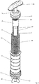
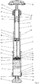
- the figures show images of a bone cement applicator according to the invention for storing starting components 3, 4 of a bone cement 48 and for mixing the bone cement 48.
- the Figures 1 and 4 to 7 show the sequence of a method according to the invention carried out with the bone cement applicator according to the invention in the form of five cross-sectional views of the bone cement applicator.
- the bone cement applicator according to the invention has a tubular cartridge 1 made of plastic, which has a front part (in the Figures 1 to 8 below) of the bone cement applicator. A rear, rear part of the bone cement applicator is formed by a receptacle 2.
- the bone cement applicator is used to produce a bone cement 48 (see Figures 5 to 7 ) is provided, which is produced from a monomer liquid 3 and from a bone cement powder 4.
- the monomer liquid 3 and the bone cement powder 4 are the starting components 3, 4 of the bone cement 48.
- the monomer liquid 3 is contained in a breakable ampoule 5 made of glass or of a plastic as a monomer liquid container for the monomer liquid 3, the ampoule 5 being in the receptacle 2.
- the cartridge 1 forms in its interior a cylindrical interior 11, in which the bone cement powder 4 is contained.
- the bone cement applicator is therefore also suitable for storing the monomer liquid 3 and the bone cement powder 4.
- the cartridge 1 has on its front side (in the figures below) a cartridge cover 6 as a cartridge head.
- a discharge opening is provided in the cartridge cover 6.
- a mixing rod 7 is attached to the front of the receptacle 2 and extends from the front of the receptacle 2 to the front part of the cartridge 1, in which the bone cement powder 4 is located.
- a threaded tube 9 with a suitable external thread 45 is screwed into this internal thread 8.
- the threaded tube 9 is closed on its front side (in the figures below) by a discharge piston 12.
- a cylindrical space 13 is formed in the interior of the threaded tube 9 its front side is delimited by the discharge piston 12 and into which the receptacle is inserted so as to be axially movable.
- the receptacle 2 has an internal thread 15 on its rear side and has a cylindrical chamber in its interior, in which the ampoule 5 is inserted. In a front region, the receptacle 2 has a cylindrical shape on the outside, four projecting strips 47 being provided on the outer surface of the receptacle 2 parallel to the cylinder axis of the receptacle 2.
- the ampoule 5 has a cylindrical ampoule body with a diameter that matches the interior of the receptacle 2. Inside the cartridge 1, the cartridge 1 forms the cylindrical interior 11.
- the cylinder geometry of the interior 11 and the chamber of the receptacle 2 correspond to cylinders with a circular base.
- a mixer 10 in the form of mixing blades with a surrounding scraping ring is attached to the front of the mixing rod 7.
- the areas can be reached directly on the inner wall of the interior 11 with the scraping ring.
- the receptacle 2 is delimited on its front by a wall with a plurality of passages 36 as a closure of the front, the wall on the front of the receptacle 2 closing the chamber forward on its circular base.
- the discharge piston 12 is arranged to be axially movable in the cylindrical interior 11 of the cartridge 1.
- the mixing rod 7 is guided through a central passage in the discharge piston 12, so that the mixing rod 7 can be moved against the discharge piston 12 without the discharge piston 12 having to move in the interior of the cartridge 1.
- the mixer 10 lies against the front of the discharge piston 12.
- the discharge plunger 12 has a plurality of channels 14 through the discharge plunger 12, which are arranged in a ring around the central passage for the mixing rod 7 in the discharge plunger 12 and the front of the discharge plunger 12 with the rear of the discharge plunger 12 and thereby the interior 11 of the cartridge 1 connect to the space 13 of the threaded tube 9.
- the channels 14 are covered with an annular pore filter 16.
- the pore filter 16 is impermeable to the bone cement powder 4 from the interior 11 of the cartridge 1 and permeable to the monomer liquid 3 and gases. Thereby penetration of the bone cement powder 4 into the space 13 of the threaded tube 9 and the interior of the receptacle 2 is prevented.
- the discharge piston 12 has a larger outside diameter than the inside diameter of the internal thread 8 of the cartridge 1.
- the outside diameter of the cylindrical discharge piston 12 matches the inside diameter of the interior 11 of the cartridge 1.
- the discharge piston 12 seals the interior 11 of the cartridge 1.
- An opening device 18 is provided on the back of the receptacle 2, by means of which the ampoule 5 can be pressed in the direction of the discharge piston 12 in order to open the ampoule 5 in the interior of the receptacle 2, so that the monomer liquid 3 flows out in the receptacle 2.
- the opening device 18 has a sleeve 20, the sleeve 20 forming a hollow cylinder in which an ampoule head of the ampoule 5 is arranged.
- the sleeve 20 of the opening device 18 can thereby press on shoulders 21 of the ampoule 5 in order to press it forward in the direction of the discharge plunger 12 and thereby open it.
- the force is conducted through the ampoule body to an ampoule base 27 of the ampoule 5.
- the walls of the ampoule body are very stable, so that the ampoule 5 will not break in this area. The ampoule 5 can thus be broken open on the ampoule base 27.
- the sleeve 20 has an external thread 26 which fits the internal thread 15 of the receptacle 2.
- the sleeve 20 is screwed into the internal thread 15 of the receptacle 2 and can be screwed deeper into the receptacle 2 in order to open the ampoule 5.
- the sleeve 20 covers the receptacle 2 in the area of the rear of the interior of the receptacle 2.
- a fixing cap 22 is screwed onto the external thread 26 of the sleeve 20.
- the sleeve 20 has a suitable rear internal thread 23.
- the fixing cap 22 serves to fix the receptacle 2 on the threaded tube 9.
- the fixing cap 22 has a front internal thread 24 which fits on the external thread 45 of the threaded tube 9.
- the bone cement applicator must be held or set up for use with the cartridge cover 6 facing down, as in FIGS Figures 1 to 8 is shown.
- the opening device 18 is screwed into the rear of the receptacle 2 to a small extent, but not so far, and thus fastened to it. It is important that the opening device 18 can be screwed even further into the receptacle 2 and thus the sleeve 20 can be pushed deeper into the receptacle 2 so that the ampoule 5 in the receptacle 2 can be opened.
- an anti-rotation lock can be provided (in FIGS Figures 1 to 8 not seen).
- the anti-rotation lock prevents the fixing cap 22 or the opening device 18 from being released from the receptacle 2.
- the anti-rotation lock can be implemented, for example, as a screw lock in the form of a locking washer or by means of a pair of wedge lock washers or similar measures.
- the rear end thereof is equipped with a handle 28.
- two circumferential seals 30 made of rubber are arranged in circumferential grooves on the foremost outer circumference of the receptacle.
- the internal thread 15 of the receptacle is limited and thus forms a stop which prevents the opening device 18 from being screwed further into the receptacle 2.
- a mandrel 34 for breaking open the ampoule 5 is arranged on the front wall of the receptacle 2 facing the cartridge cover 6. For this purpose, the mandrel 34 points into the interior of the receptacle 2.
- the ampoule 5 can be pressed onto the mandrel 34 with the sleeve 20 to open the ampoule 5 until the ampoule base 27 of the ampoule 5 is pressed into the ampoule body.
- the mandrel 34 has a blunt tip, which serves for the force on the ampoule 5 to act on a central region of the ampoule base 27, so that a predetermined breaking point is used in the connection between the ampoule base 27 and the side walls of the ampoule body.
- the force for this is exerted via the sleeve 20.
- the sleeve 20 has approximately the same Diameter as the ampoule body of the ampoule 5.
- the ampoule head of the ampoule 5 is arranged inside the sleeve 20. This ensures that the ampoule 5 is not broken in the area of the sleeve 20 because the cylindrical ampoule body is very stable, while the mandrel 34 can be pressed into the ampoule 5 from the front relatively easily.
- the mixing rod 7 is fastened to the receptacle 2 within the mandrel 34.
- the mandrel 34 is connected to the receptacle 2 via a predetermined breaking point, so that when the mixing rod 7 is pressed, the mixing rod 7 separates the mandrel 34 from the receptacle 2 and thus the mixing rod 7 with the mandrel 34 at the tip through the front base surface the recording 2 is movable.
- an inner circular disk (not shown) of the front side of the receptacle 2 can also be connected to the receptacle 2 via a thread, so that the mandrel 34 with this circular disk is rotated by rotating the receptacle 2 against the mixing rod 7 of FIG the remaining receptacle 2 can be separated so that the mixing rod 7 is again movable against the remaining receptacle 2.
- a plurality of passages 36 are arranged around the mandrel 34, which connect the interior of the receptacle 1 to the interior 11 of the cartridge 1.
- the monomer liquid 3 can flow through the passages 36 into the interior 11 of the cartridge 1, as in FIG Figure 4 is shown.
- the front of the cartridge 1 is closed with the cartridge cover 6.
- a socket 37 is formed, which delimits the discharge opening in the cartridge cover 6.
- a closure 38 is screwed into the connecting piece 37 and thereby releasably fastened, which closes the discharge opening.
- the closure 38 can be operated via wing 39 in the manner of a wing screw.
- the cartridge cover 6 is screwed with an internal thread 40 onto an external thread 42 on the front of the cartridge 1.
- the cartridge cover 6 is additionally sealed against the cartridge 1 by a circumferential seal 43.
- the mixer 10 In the front part of the interior 11 of the cartridge 1 is the mixer 10, with which the content of the front part of the interior 11 can be mixed by a manual movement of the mixer 10.
- the manual movement of the mixer 10 takes place by inserting and withdrawing the receptacle 2 into the threaded tube 9.
- the mixing rod 7, which is attached to the front of the receptacle 2, is also moved back and forth linearly.
- the mixing rod 7 moves through the passage in the discharge piston 12 and the mixer 10 attached to the mixing rod 7 moves in the interior 11 of the cartridge 1.
- the mixer 10 hits the cartridge cover 6, provided that the threaded tube 9 does not exceed the back of the interior 11 up to a stop formed by the internal thread 8 of the cartridge 1 and the delivery piston 12 the cartridge 1 is unscrewed.
- the length of the mixing rod 7 is selected so that the mixer 10 lies precisely against the cartridge cover 6 on the front of the interior 11. As a result, the bone cement 48 can also be completely reached and mixed with the mixer 10 on the front of the interior 11.
- the closure 38 protrudes a little bit into the interior 11 of the cartridge 1.
- a recess is provided which receives the part of the closure 38 which projects into the interior 11.
- the bone cement 48 lying on the closure 38 and on the cartridge cover 6 can also be mixed, and at the same time a free flow cross section is provided for the bone cement 48 through this depression when the closure 38 is removed and the mixer 10 is in contact with the cartridge cover 6 when the bone cement 48 is being discharged (please refer Figure 7 ).
- the bone cement applicator is in the initial state (see Figures 1 to 3 and 8th ).
- the bone cement applicator has been packaged and sterilized with ethylene oxide.
- the ethylene oxide can pass through spaces in the opening device 18 into the interior of the receptacle 2 and through the passages 36, the pore filter 16 and the channels 14 into the interior 11 of the cartridge 1.
- the gas exchange takes place in a vacuum chamber or vacuum chamber.
- the bone cement applicator is unpacked.
- the bone cement applicator is held with the cartridge cover 6 facing down.
- the opening device 18 is then screwed into the receptacle 2.
- the bone cement applicator is held down with the cartridge cover 6.
- the sleeve 20 presses the ampoule 5 down on its shoulders 21.
- the ampoule 5 with the ampoule base 27 is pressed onto the mandrel 34 and the ampoule 5 breaks open at the ampoule base 27. This state is in Figure 4 shown.
- the monomer liquid 3 emerges from the opened ampoule 5 in the region of the passages 36. Since the bone cement applicator is held with the cartridge cover 6 downward, the monomer liquid 3 flows downward through the force of gravity Passages 36, the pore filter 16 and the channels 14 into the interior 11 of the cartridge 1 and are distributed in the bone cement powder 4 (see Figure 4 ). In order to accelerate the monomer transfer, the receptacle 2 can be pushed into the threaded tube 9 and pulled out.
- the bone cement 48 or the starting components 3, 4 of the bone cement 48 are mixed by inserting and pulling out the receptacle 2 in the space 13 of the threaded tube 9 while simultaneously moving the mixer 10 in the interior 11 of the cartridge 1.
- the mixer 10 reaches all locations in FIG the interior 11 between the discharge piston 12 and the cartridge cover 6.
- the strips 47 are arranged on the outside of the receptacle 2. The strips 47 prevent the holder 2 from wobbling during mixing.
- the receptacle 2 can be screwed into the cartridge 1 together with the threaded tube 9.
- the receptacle 2 can be moved powerfully against the cartridge 1.
- the mixer 10 lies against the cartridge cover 6 at the front, so that the mixing rod 7 cannot escape.
- the pressure imparted by the mixing rod 7 releases the mandrel 34 from the front wall of the receptacle 2 or the mixing rod 7 penetrates the mandrel 34.
- the discharge piston 12 is also driven in the interior 11 in the direction of the cartridge cover 6.
- the bone cement 48 When screwing the receptacle 2 further into the cartridge 1, the bone cement 48 is expelled from the interior 11 of the cartridge 1 through the opened discharge opening.
- the closure 38 is previously screwed out of the discharge opening and a discharge tube 49 is screwed into the internal thread of the socket 37.
- the discharge pipe 49 has an external thread that matches the internal thread of the connector 37.
- the bone cement 48 is pressed between the mixer 10 and the cartridge cover 6 through the discharge opening and the nozzle 37 into the discharge tube 49. The bone cement 48 then flows out of the discharge tube 49 and is ready for use (see Figure 7 ).
- a tube with a trocar (not shown) can also be attached to the nozzle 37, through which the bone cement 48 can be applied under difficult X-ray locations under X-ray control.
Landscapes
- Health & Medical Sciences (AREA)
- Orthopedic Medicine & Surgery (AREA)
- Surgery (AREA)
- Life Sciences & Earth Sciences (AREA)
- Chemical Kinetics & Catalysis (AREA)
- Chemical & Material Sciences (AREA)
- Medical Informatics (AREA)
- Heart & Thoracic Surgery (AREA)
- Biomedical Technology (AREA)
- Molecular Biology (AREA)
- Animal Behavior & Ethology (AREA)
- General Health & Medical Sciences (AREA)
- Public Health (AREA)
- Veterinary Medicine (AREA)
- Engineering & Computer Science (AREA)
- Nuclear Medicine, Radiotherapy & Molecular Imaging (AREA)
- Prostheses (AREA)
- Materials For Medical Uses (AREA)
- Surgical Instruments (AREA)
Applications Claiming Priority (1)
| Application Number | Priority Date | Filing Date | Title |
|---|---|---|---|
| DE102018209807.7A DE102018209807A1 (de) | 2018-06-18 | 2018-06-18 | Knochenzementapplikator mit versenkbarem Mischstab und Verfahren zur Herstellung eines Knochenzements |
Publications (2)
| Publication Number | Publication Date |
|---|---|
| EP3584005A1 true EP3584005A1 (fr) | 2019-12-25 |
| EP3584005B1 EP3584005B1 (fr) | 2020-11-11 |
Family
ID=66630208
Family Applications (1)
| Application Number | Title | Priority Date | Filing Date |
|---|---|---|---|
| EP19180576.1A Active EP3584005B1 (fr) | 2018-06-18 | 2019-06-17 | Applicateur de ciment osseux pourvu de bâton mélangeur pouvant être abaissé et procédé de fabrication d'un ciment osseux |
Country Status (7)
| Country | Link |
|---|---|
| US (1) | US11109905B2 (fr) |
| EP (1) | EP3584005B1 (fr) |
| JP (1) | JP6876097B2 (fr) |
| CN (1) | CN110613505B (fr) |
| AU (1) | AU2019203699B2 (fr) |
| CA (1) | CA3047044C (fr) |
| DE (1) | DE102018209807A1 (fr) |
Cited By (1)
| Publication number | Priority date | Publication date | Assignee | Title |
|---|---|---|---|---|
| EP4566701A1 (fr) * | 2023-12-07 | 2025-06-11 | Heraeus Medical GmbH | Kit pour la préparation et l'extraction de ciment osseux et procédé |
Families Citing this family (13)
| Publication number | Priority date | Publication date | Assignee | Title |
|---|---|---|---|---|
| DE102017125592B4 (de) * | 2017-11-02 | 2019-06-19 | Heraeus Medical Gmbh | Pulver-Flüssigkeits-Knochenzementmischer mit Druckgasanschluss |
| DE102018209784A1 (de) * | 2018-06-18 | 2019-12-19 | Heraeus Medical Gmbh | Knochenzementapplikator mit versenkbarem Mischstab und Verfahren zur Herstellung eines Knochenzements |
| EP3643399B1 (fr) * | 2018-10-25 | 2022-04-27 | Heraeus Medical GmbH | Dispositif et procédé de fourniture de ciment osseux |
| CN111839707B (zh) * | 2020-06-30 | 2021-07-20 | 陈丹华 | 一种椎体成形系统骨水泥推进器 |
| CN111870259B (zh) * | 2020-07-31 | 2023-09-29 | 武汉轻工大学 | 动物血液采集血清分离针 |
| DE102020130998A1 (de) | 2020-11-24 | 2022-05-25 | Heraeus Medical Gmbh | Lichtleitender Austragsschnorchel für Knochenzementteige |
| EP4154973B1 (fr) * | 2021-09-28 | 2024-01-17 | Heraeus Medical GmbH | Dispositif de préparation de pâte de ciment osseux |
| CN114699983A (zh) * | 2022-03-31 | 2022-07-05 | 广西科技师范学院 | 一种蔗汁用辅料自动下料装置 |
| EP4282518B1 (fr) * | 2022-05-23 | 2024-07-03 | Heraeus Medical GmbH | Dispositif et procédé de préparation de la pâte de ciment osseux |
| EP4299169B1 (fr) * | 2022-06-30 | 2024-07-31 | Heraeus Medical GmbH | Dispositif et procédé de fourniture de la pâte de ciment osseux |
| US11737802B1 (en) | 2022-07-25 | 2023-08-29 | Zavation Medical Products, Llc | Bone cement mixer |
| CN116746977B (zh) * | 2023-06-25 | 2024-12-24 | 广东博迈医疗科技股份有限公司 | 一种机械式解脱弹簧圈系统及其制造方法、使用方法 |
| EP4616936A1 (fr) * | 2024-03-15 | 2025-09-17 | Heraeus Medical GmbH | Système de mélange de ciment osseux comprenant un composé de perçage et un piston multifonctionnel |
Citations (18)
| Publication number | Priority date | Publication date | Assignee | Title |
|---|---|---|---|---|
| US4671263A (en) | 1984-07-11 | 1987-06-09 | Klaus Draenert | Device and process for mixing and applying bone cement |
| DE3640279A1 (de) | 1985-12-23 | 1987-06-25 | Mit Ab | Geraet zum mischen von knochenzement im vakuum |
| US4973168A (en) | 1989-01-13 | 1990-11-27 | Chan Kwan Ho | Vacuum mixing/bone cement cartridge and kit |
| US5344232A (en) | 1991-09-30 | 1994-09-06 | Stryker Corporation | Bone cement mixing and loading apparatus |
| WO1994026403A1 (fr) | 1993-05-10 | 1994-11-24 | Cemvac System Ab | Procede et dispositif permettant d'introduire des constituants d'un ciment pour les os dans un recipient ou ils doivent etre melanges |
| EP0692229A1 (fr) | 1994-07-16 | 1996-01-17 | MERCK PATENT GmbH | Dispositif pour mélanger et appliquer un ciment osseux |
| US5586821A (en) | 1995-10-10 | 1996-12-24 | Zimmer, Inc. | Bone cement preparation kit |
| US5588745A (en) | 1994-09-02 | 1996-12-31 | Howmedica | Methods and apparatus for mixing bone cement components using an evacuated mixing chamber |
| WO1997018031A1 (fr) * | 1995-11-13 | 1997-05-22 | Cemvac System Ab | Procede et dispositif d'amenee de composants dans un vase de melange pour la preparation d'un ciment osseux |
| EP0796653A2 (fr) | 1996-02-21 | 1997-09-24 | Kwan-Ho Chan | Dispositif et procédé pour le malaxage d'un ciment pour os |
| US5997544A (en) | 1997-05-02 | 1999-12-07 | Merck Patent Gesellschaft Mit Beschrankter Haftung | Process and device for producing sterile-packed bone cement |
| WO1999067015A1 (fr) | 1997-05-21 | 1999-12-29 | Nikomed Aps | Appareil pour la preparation de ciment osseux |
| US6033105A (en) | 1996-11-15 | 2000-03-07 | Barker; Donald | Integrated bone cement mixing and dispensing system |
| WO2000035506A1 (fr) | 1998-12-14 | 2000-06-22 | Ao Research Institute Davos | Procede de preparation de ciment osseux |
| EP1020167A2 (fr) | 1999-01-14 | 2000-07-19 | Bristol-Myers Squibb Company | Dispositif et procédé pour mélanger et appliquer du ciment osseux |
| EP1886647A1 (fr) | 2006-08-11 | 2008-02-13 | Biomet Cementing Technologies AB | Dispositif de mélangeur de ciment osseux |
| DE102009031178B3 (de) | 2009-06-29 | 2010-09-16 | Heraeus Medical Gmbh | Vorrichtung zum Mischen und Austragen von Knochenzement |
| DE102016121607A1 (de) | 2016-11-11 | 2018-05-17 | Heraeus Medical Gmbh | Vorrichtung und Verfahren zum Lagern und Mischen eines Knochenzements |
Family Cites Families (6)
| Publication number | Priority date | Publication date | Assignee | Title |
|---|---|---|---|---|
| US6547432B2 (en) * | 2001-07-16 | 2003-04-15 | Stryker Instruments | Bone cement mixing and delivery device for injection and method thereof |
| EP1903961B1 (fr) * | 2005-07-07 | 2012-05-16 | Crosstrees Medical, Inc. | Dispositif d'administration de materiaux de remplissage de vide osseux |
| SE530233C2 (sv) * | 2006-08-11 | 2008-04-08 | Biomet Cementing Technologies | Vätskebehållare för bencementblandare |
| KR101544922B1 (ko) * | 2014-06-23 | 2015-08-18 | (주)인젝타 | 골시멘트 혼합 및 주입용 카트리지 및 상기 카트리지를 포함하는 골시멘트 혼합 및 전달시스템 |
| DE102016113468A1 (de) * | 2016-07-21 | 2018-01-25 | Heraeus Medical Gmbh | Knochenzement-Applikator mit Dreiwege-Ventil zur Druckentlastung |
| DE102016121606B4 (de) * | 2016-11-11 | 2019-05-02 | Heraeus Medical Gmbh | Knochenzementapplikator mit durch Knochenzementteig angetriebenem Verschlusssystem und Verfahren zum Applizieren eines Knochenzements |
-
2018
- 2018-06-18 DE DE102018209807.7A patent/DE102018209807A1/de not_active Ceased
-
2019
- 2019-05-27 AU AU2019203699A patent/AU2019203699B2/en not_active Ceased
- 2019-06-06 JP JP2019105817A patent/JP6876097B2/ja not_active Expired - Fee Related
- 2019-06-17 US US16/443,158 patent/US11109905B2/en active Active
- 2019-06-17 EP EP19180576.1A patent/EP3584005B1/fr active Active
- 2019-06-18 CN CN201910525508.6A patent/CN110613505B/zh not_active Expired - Fee Related
- 2019-06-18 CA CA3047044A patent/CA3047044C/fr active Active
Patent Citations (23)
| Publication number | Priority date | Publication date | Assignee | Title |
|---|---|---|---|---|
| US4671263A (en) | 1984-07-11 | 1987-06-09 | Klaus Draenert | Device and process for mixing and applying bone cement |
| DE3640279A1 (de) | 1985-12-23 | 1987-06-25 | Mit Ab | Geraet zum mischen von knochenzement im vakuum |
| US4973168A (en) | 1989-01-13 | 1990-11-27 | Chan Kwan Ho | Vacuum mixing/bone cement cartridge and kit |
| US5100241A (en) | 1989-01-13 | 1992-03-31 | Chan Kwan Ho | Vacuum mixing/bone cement cartridge and kit |
| US5344232A (en) | 1991-09-30 | 1994-09-06 | Stryker Corporation | Bone cement mixing and loading apparatus |
| WO1994026403A1 (fr) | 1993-05-10 | 1994-11-24 | Cemvac System Ab | Procede et dispositif permettant d'introduire des constituants d'un ciment pour les os dans un recipient ou ils doivent etre melanges |
| EP0692229A1 (fr) | 1994-07-16 | 1996-01-17 | MERCK PATENT GmbH | Dispositif pour mélanger et appliquer un ciment osseux |
| US5588745A (en) | 1994-09-02 | 1996-12-31 | Howmedica | Methods and apparatus for mixing bone cement components using an evacuated mixing chamber |
| US5586821A (en) | 1995-10-10 | 1996-12-24 | Zimmer, Inc. | Bone cement preparation kit |
| US5624184A (en) | 1995-10-10 | 1997-04-29 | Chan; Kwan-Ho | Bone cement preparation kit having a breakable mixing shaft forming an output port |
| WO1997018031A1 (fr) * | 1995-11-13 | 1997-05-22 | Cemvac System Ab | Procede et dispositif d'amenee de composants dans un vase de melange pour la preparation d'un ciment osseux |
| EP1005901A2 (fr) | 1995-11-13 | 2000-06-07 | Cemvac System Aktiebolag | Procédé et dispositif pour mélanger des composants pour un ciment osseux dans un récipient de mélange |
| EP1016452A2 (fr) | 1995-11-13 | 2000-07-05 | Cemvac System Aktiebolag | Procédé et dispositif pour mélanger des composants pour un ciment osseux dans un récipient de mélange |
| EP0796653A2 (fr) | 1996-02-21 | 1997-09-24 | Kwan-Ho Chan | Dispositif et procédé pour le malaxage d'un ciment pour os |
| US6033105A (en) | 1996-11-15 | 2000-03-07 | Barker; Donald | Integrated bone cement mixing and dispensing system |
| US5997544A (en) | 1997-05-02 | 1999-12-07 | Merck Patent Gesellschaft Mit Beschrankter Haftung | Process and device for producing sterile-packed bone cement |
| WO1999067015A1 (fr) | 1997-05-21 | 1999-12-29 | Nikomed Aps | Appareil pour la preparation de ciment osseux |
| WO2000035506A1 (fr) | 1998-12-14 | 2000-06-22 | Ao Research Institute Davos | Procede de preparation de ciment osseux |
| US6709149B1 (en) | 1998-12-14 | 2004-03-23 | Ao Research Institute Davos | Method of bone cement preparation |
| EP1020167A2 (fr) | 1999-01-14 | 2000-07-19 | Bristol-Myers Squibb Company | Dispositif et procédé pour mélanger et appliquer du ciment osseux |
| EP1886647A1 (fr) | 2006-08-11 | 2008-02-13 | Biomet Cementing Technologies AB | Dispositif de mélangeur de ciment osseux |
| DE102009031178B3 (de) | 2009-06-29 | 2010-09-16 | Heraeus Medical Gmbh | Vorrichtung zum Mischen und Austragen von Knochenzement |
| DE102016121607A1 (de) | 2016-11-11 | 2018-05-17 | Heraeus Medical Gmbh | Vorrichtung und Verfahren zum Lagern und Mischen eines Knochenzements |
Non-Patent Citations (1)
| Title |
|---|
| CHARNLEY, J.: "Anchorage of the femoral head prosthesis of the shaft of the femur", J. BONE JOINT SURG., vol. 42, 1960, pages 28 - 30 |
Cited By (2)
| Publication number | Priority date | Publication date | Assignee | Title |
|---|---|---|---|---|
| EP4566701A1 (fr) * | 2023-12-07 | 2025-06-11 | Heraeus Medical GmbH | Kit pour la préparation et l'extraction de ciment osseux et procédé |
| AU2024266888B2 (en) * | 2023-12-07 | 2025-10-09 | Heraeus Medical Gmbh | Kit for producing and extruding bone cement, and method |
Also Published As
| Publication number | Publication date |
|---|---|
| JP6876097B2 (ja) | 2021-05-26 |
| CN110613505A (zh) | 2019-12-27 |
| US20190380758A1 (en) | 2019-12-19 |
| EP3584005B1 (fr) | 2020-11-11 |
| CA3047044A1 (fr) | 2019-12-18 |
| JP2020011051A (ja) | 2020-01-23 |
| US11109905B2 (en) | 2021-09-07 |
| DE102018209807A1 (de) | 2019-12-19 |
| CA3047044C (fr) | 2021-06-15 |
| CN110613505B (zh) | 2022-06-28 |
| AU2019203699B2 (en) | 2020-04-09 |
| AU2019203699A1 (en) | 2020-01-16 |
Similar Documents
| Publication | Publication Date | Title |
|---|---|---|
| EP3584005B1 (fr) | Applicateur de ciment osseux pourvu de bâton mélangeur pouvant être abaissé et procédé de fabrication d'un ciment osseux | |
| EP3524341B1 (fr) | Applicateur de ciment osseux pourvu d'ouverture de chargement de gaz pouvant être fermée | |
| EP3584004B1 (fr) | Applicateur de ciment osseux pourvu de bâton mélangeur pouvant être abaissé et procédé de fabrication d'un ciment osseux | |
| EP3662990B1 (fr) | Dispositif de mélange d'un ciment osseux pourvu de cavité pour un transfert au monomère et procédé | |
| EP3395274B1 (fr) | Dispositif d'application de ciment osseux pourvu de moyen de fermeture sur le piston de distribution | |
| EP3372306B1 (fr) | Dispositif de stockage et de mélange en deux parties destiné à la production d'un ciment osseux et procédé correspondant | |
| EP3384866B1 (fr) | Dispositif de stockage, de mélange et de distribution d'un ciment osseux et procédé correspondant | |
| DE102010019217B4 (de) | Kartuschensystem | |
| EP3403716B1 (fr) | Applicateur de ciment osseux doté du cylindre creux au niveau du piston de distribution | |
| EP3260193B1 (fr) | Dispositif de mélange et de stockage pour ciment osseux à l'aide d'une pompe de refoulement et procédé pour mélanger un ciment osseux | |
| EP3100694B1 (fr) | Dispositif et procédé de mélange et de stockage de ciment osseux en polyméthacrylate de méthyle | |
| EP3260192B1 (fr) | Dispositif de stockage et de mélange destiné à produire un ciment osseux et procédé pour mélanger ciment osseux | |
| EP3505237B1 (fr) | Dispositif et procede de mélange de ciment osseux pourvu d'écarteur dans un logement à ampoule | |
| EP3231505A1 (fr) | Dispositif de mélange et de stockage de ciment osseux en polyméthacrylate de méthyle comprenant une pompe de refoulement et dispositif d'ouverture d'ampoules | |
| EP1520562B1 (fr) | Dispositif pour mélanger et distribuer des substances liquides et pulvérulentes pour l'utilisation médicale. | |
| EP3662991B1 (fr) | Dispositif et procédé de mélange d'un ciment osseux pourvu de cavité pour un transfert au monomère | |
| EP3479895B1 (fr) | Mélangeur de ciment osseux, de liquide et de poudre pourvu de raccordement de gaz de pression et procédé | |
| EP3415226B1 (fr) | Applicateur de ciment osseux pourvu d'élément conducteur et logement de fermeture | |
| EP4063007B1 (fr) | Procédé et dispositif de mélange du ciment osseux à dépressurisation |
Legal Events
| Date | Code | Title | Description |
|---|---|---|---|
| PUAI | Public reference made under article 153(3) epc to a published international application that has entered the european phase |
Free format text: ORIGINAL CODE: 0009012 |
|
| STAA | Information on the status of an ep patent application or granted ep patent |
Free format text: STATUS: REQUEST FOR EXAMINATION WAS MADE |
|
| 17P | Request for examination filed |
Effective date: 20190617 |
|
| AK | Designated contracting states |
Kind code of ref document: A1 Designated state(s): AL AT BE BG CH CY CZ DE DK EE ES FI FR GB GR HR HU IE IS IT LI LT LU LV MC MK MT NL NO PL PT RO RS SE SI SK SM TR |
|
| AX | Request for extension of the european patent |
Extension state: BA ME |
|
| GRAP | Despatch of communication of intention to grant a patent |
Free format text: ORIGINAL CODE: EPIDOSNIGR1 |
|
| STAA | Information on the status of an ep patent application or granted ep patent |
Free format text: STATUS: GRANT OF PATENT IS INTENDED |
|
| INTG | Intention to grant announced |
Effective date: 20200710 |
|
| RIC1 | Information provided on ipc code assigned before grant |
Ipc: B01F 13/00 20060101ALI20200626BHEP Ipc: B01F 11/00 20060101AFI20200626BHEP Ipc: B01F 15/02 20060101ALI20200626BHEP Ipc: A61B 17/88 20060101ALI20200626BHEP Ipc: B01F 15/00 20060101ALI20200626BHEP |
|
| GRAS | Grant fee paid |
Free format text: ORIGINAL CODE: EPIDOSNIGR3 |
|
| GRAA | (expected) grant |
Free format text: ORIGINAL CODE: 0009210 |
|
| STAA | Information on the status of an ep patent application or granted ep patent |
Free format text: STATUS: THE PATENT HAS BEEN GRANTED |
|
| AK | Designated contracting states |
Kind code of ref document: B1 Designated state(s): AL AT BE BG CH CY CZ DE DK EE ES FI FR GB GR HR HU IE IS IT LI LT LU LV MC MK MT NL NO PL PT RO RS SE SI SK SM TR |
|
| REG | Reference to a national code |
Ref country code: GB Ref legal event code: FG4D Free format text: NOT ENGLISH |
|
| REG | Reference to a national code |
Ref country code: CH Ref legal event code: EP |
|
| REG | Reference to a national code |
Ref country code: AT Ref legal event code: REF Ref document number: 1332921 Country of ref document: AT Kind code of ref document: T Effective date: 20201115 |
|
| REG | Reference to a national code |
Ref country code: DE Ref legal event code: R096 Ref document number: 502019000392 Country of ref document: DE |
|
| REG | Reference to a national code |
Ref country code: IE Ref legal event code: FG4D Free format text: LANGUAGE OF EP DOCUMENT: GERMAN |
|
| REG | Reference to a national code |
Ref country code: CH Ref legal event code: NV Representative=s name: DENNEMEYER AG, CH |
|
| REG | Reference to a national code |
Ref country code: NL Ref legal event code: MP Effective date: 20201111 |
|
| PG25 | Lapsed in a contracting state [announced via postgrant information from national office to epo] |
Ref country code: PT Free format text: LAPSE BECAUSE OF FAILURE TO SUBMIT A TRANSLATION OF THE DESCRIPTION OR TO PAY THE FEE WITHIN THE PRESCRIBED TIME-LIMIT Effective date: 20210311 Ref country code: RS Free format text: LAPSE BECAUSE OF FAILURE TO SUBMIT A TRANSLATION OF THE DESCRIPTION OR TO PAY THE FEE WITHIN THE PRESCRIBED TIME-LIMIT Effective date: 20201111 Ref country code: FI Free format text: LAPSE BECAUSE OF FAILURE TO SUBMIT A TRANSLATION OF THE DESCRIPTION OR TO PAY THE FEE WITHIN THE PRESCRIBED TIME-LIMIT Effective date: 20201111 Ref country code: GR Free format text: LAPSE BECAUSE OF FAILURE TO SUBMIT A TRANSLATION OF THE DESCRIPTION OR TO PAY THE FEE WITHIN THE PRESCRIBED TIME-LIMIT Effective date: 20210212 Ref country code: NO Free format text: LAPSE BECAUSE OF FAILURE TO SUBMIT A TRANSLATION OF THE DESCRIPTION OR TO PAY THE FEE WITHIN THE PRESCRIBED TIME-LIMIT Effective date: 20210211 |
|
| PG25 | Lapsed in a contracting state [announced via postgrant information from national office to epo] |
Ref country code: BG Free format text: LAPSE BECAUSE OF FAILURE TO SUBMIT A TRANSLATION OF THE DESCRIPTION OR TO PAY THE FEE WITHIN THE PRESCRIBED TIME-LIMIT Effective date: 20210211 Ref country code: SE Free format text: LAPSE BECAUSE OF FAILURE TO SUBMIT A TRANSLATION OF THE DESCRIPTION OR TO PAY THE FEE WITHIN THE PRESCRIBED TIME-LIMIT Effective date: 20201111 Ref country code: LV Free format text: LAPSE BECAUSE OF FAILURE TO SUBMIT A TRANSLATION OF THE DESCRIPTION OR TO PAY THE FEE WITHIN THE PRESCRIBED TIME-LIMIT Effective date: 20201111 Ref country code: PL Free format text: LAPSE BECAUSE OF FAILURE TO SUBMIT A TRANSLATION OF THE DESCRIPTION OR TO PAY THE FEE WITHIN THE PRESCRIBED TIME-LIMIT Effective date: 20201111 Ref country code: IS Free format text: LAPSE BECAUSE OF FAILURE TO SUBMIT A TRANSLATION OF THE DESCRIPTION OR TO PAY THE FEE WITHIN THE PRESCRIBED TIME-LIMIT Effective date: 20210311 |
|
| REG | Reference to a national code |
Ref country code: LT Ref legal event code: MG9D |
|
| PG25 | Lapsed in a contracting state [announced via postgrant information from national office to epo] |
Ref country code: HR Free format text: LAPSE BECAUSE OF FAILURE TO SUBMIT A TRANSLATION OF THE DESCRIPTION OR TO PAY THE FEE WITHIN THE PRESCRIBED TIME-LIMIT Effective date: 20201111 |
|
| PG25 | Lapsed in a contracting state [announced via postgrant information from national office to epo] |
Ref country code: SM Free format text: LAPSE BECAUSE OF FAILURE TO SUBMIT A TRANSLATION OF THE DESCRIPTION OR TO PAY THE FEE WITHIN THE PRESCRIBED TIME-LIMIT Effective date: 20201111 Ref country code: SK Free format text: LAPSE BECAUSE OF FAILURE TO SUBMIT A TRANSLATION OF THE DESCRIPTION OR TO PAY THE FEE WITHIN THE PRESCRIBED TIME-LIMIT Effective date: 20201111 Ref country code: EE Free format text: LAPSE BECAUSE OF FAILURE TO SUBMIT A TRANSLATION OF THE DESCRIPTION OR TO PAY THE FEE WITHIN THE PRESCRIBED TIME-LIMIT Effective date: 20201111 Ref country code: CZ Free format text: LAPSE BECAUSE OF FAILURE TO SUBMIT A TRANSLATION OF THE DESCRIPTION OR TO PAY THE FEE WITHIN THE PRESCRIBED TIME-LIMIT Effective date: 20201111 Ref country code: LT Free format text: LAPSE BECAUSE OF FAILURE TO SUBMIT A TRANSLATION OF THE DESCRIPTION OR TO PAY THE FEE WITHIN THE PRESCRIBED TIME-LIMIT Effective date: 20201111 Ref country code: RO Free format text: LAPSE BECAUSE OF FAILURE TO SUBMIT A TRANSLATION OF THE DESCRIPTION OR TO PAY THE FEE WITHIN THE PRESCRIBED TIME-LIMIT Effective date: 20201111 |
|
| REG | Reference to a national code |
Ref country code: DE Ref legal event code: R097 Ref document number: 502019000392 Country of ref document: DE |
|
| PG25 | Lapsed in a contracting state [announced via postgrant information from national office to epo] |
Ref country code: DK Free format text: LAPSE BECAUSE OF FAILURE TO SUBMIT A TRANSLATION OF THE DESCRIPTION OR TO PAY THE FEE WITHIN THE PRESCRIBED TIME-LIMIT Effective date: 20201111 |
|
| PLBE | No opposition filed within time limit |
Free format text: ORIGINAL CODE: 0009261 |
|
| STAA | Information on the status of an ep patent application or granted ep patent |
Free format text: STATUS: NO OPPOSITION FILED WITHIN TIME LIMIT |
|
| 26N | No opposition filed |
Effective date: 20210812 |
|
| PG25 | Lapsed in a contracting state [announced via postgrant information from national office to epo] |
Ref country code: IT Free format text: LAPSE BECAUSE OF FAILURE TO SUBMIT A TRANSLATION OF THE DESCRIPTION OR TO PAY THE FEE WITHIN THE PRESCRIBED TIME-LIMIT Effective date: 20201111 Ref country code: AL Free format text: LAPSE BECAUSE OF FAILURE TO SUBMIT A TRANSLATION OF THE DESCRIPTION OR TO PAY THE FEE WITHIN THE PRESCRIBED TIME-LIMIT Effective date: 20201111 Ref country code: NL Free format text: LAPSE BECAUSE OF FAILURE TO SUBMIT A TRANSLATION OF THE DESCRIPTION OR TO PAY THE FEE WITHIN THE PRESCRIBED TIME-LIMIT Effective date: 20201111 |
|
| REG | Reference to a national code |
Ref country code: DE Ref legal event code: R079 Ref document number: 502019000392 Country of ref document: DE Free format text: PREVIOUS MAIN CLASS: B01F0011000000 Ipc: B01F0031000000 |
|
| PG25 | Lapsed in a contracting state [announced via postgrant information from national office to epo] |
Ref country code: SI Free format text: LAPSE BECAUSE OF FAILURE TO SUBMIT A TRANSLATION OF THE DESCRIPTION OR TO PAY THE FEE WITHIN THE PRESCRIBED TIME-LIMIT Effective date: 20201111 |
|
| PG25 | Lapsed in a contracting state [announced via postgrant information from national office to epo] |
Ref country code: MC Free format text: LAPSE BECAUSE OF FAILURE TO SUBMIT A TRANSLATION OF THE DESCRIPTION OR TO PAY THE FEE WITHIN THE PRESCRIBED TIME-LIMIT Effective date: 20201111 Ref country code: ES Free format text: LAPSE BECAUSE OF FAILURE TO SUBMIT A TRANSLATION OF THE DESCRIPTION OR TO PAY THE FEE WITHIN THE PRESCRIBED TIME-LIMIT Effective date: 20201111 |
|
| REG | Reference to a national code |
Ref country code: BE Ref legal event code: MM Effective date: 20210630 |
|
| PG25 | Lapsed in a contracting state [announced via postgrant information from national office to epo] |
Ref country code: LU Free format text: LAPSE BECAUSE OF NON-PAYMENT OF DUE FEES Effective date: 20210617 |
|
| PG25 | Lapsed in a contracting state [announced via postgrant information from national office to epo] |
Ref country code: IE Free format text: LAPSE BECAUSE OF NON-PAYMENT OF DUE FEES Effective date: 20210617 |
|
| PG25 | Lapsed in a contracting state [announced via postgrant information from national office to epo] |
Ref country code: IS Free format text: LAPSE BECAUSE OF FAILURE TO SUBMIT A TRANSLATION OF THE DESCRIPTION OR TO PAY THE FEE WITHIN THE PRESCRIBED TIME-LIMIT Effective date: 20210311 |
|
| PG25 | Lapsed in a contracting state [announced via postgrant information from national office to epo] |
Ref country code: BE Free format text: LAPSE BECAUSE OF NON-PAYMENT OF DUE FEES Effective date: 20210630 |
|
| PG25 | Lapsed in a contracting state [announced via postgrant information from national office to epo] |
Ref country code: CY Free format text: LAPSE BECAUSE OF FAILURE TO SUBMIT A TRANSLATION OF THE DESCRIPTION OR TO PAY THE FEE WITHIN THE PRESCRIBED TIME-LIMIT Effective date: 20201111 |
|
| P01 | Opt-out of the competence of the unified patent court (upc) registered |
Effective date: 20230528 |
|
| PG25 | Lapsed in a contracting state [announced via postgrant information from national office to epo] |
Ref country code: HU Free format text: LAPSE BECAUSE OF FAILURE TO SUBMIT A TRANSLATION OF THE DESCRIPTION OR TO PAY THE FEE WITHIN THE PRESCRIBED TIME-LIMIT; INVALID AB INITIO Effective date: 20190617 |
|
| GBPC | Gb: european patent ceased through non-payment of renewal fee |
Effective date: 20230617 |
|
| PG25 | Lapsed in a contracting state [announced via postgrant information from national office to epo] |
Ref country code: MK Free format text: LAPSE BECAUSE OF FAILURE TO SUBMIT A TRANSLATION OF THE DESCRIPTION OR TO PAY THE FEE WITHIN THE PRESCRIBED TIME-LIMIT Effective date: 20201111 Ref country code: GB Free format text: LAPSE BECAUSE OF NON-PAYMENT OF DUE FEES Effective date: 20230617 |
|
| PG25 | Lapsed in a contracting state [announced via postgrant information from national office to epo] |
Ref country code: MT Free format text: LAPSE BECAUSE OF FAILURE TO SUBMIT A TRANSLATION OF THE DESCRIPTION OR TO PAY THE FEE WITHIN THE PRESCRIBED TIME-LIMIT Effective date: 20201111 |
|
| PGFP | Annual fee paid to national office [announced via postgrant information from national office to epo] |
Ref country code: DE Payment date: 20250618 Year of fee payment: 7 |
|
| PGFP | Annual fee paid to national office [announced via postgrant information from national office to epo] |
Ref country code: FR Payment date: 20250626 Year of fee payment: 7 |
|
| REG | Reference to a national code |
Ref country code: AT Ref legal event code: MM01 Ref document number: 1332921 Country of ref document: AT Kind code of ref document: T Effective date: 20240617 |
|
| PG25 | Lapsed in a contracting state [announced via postgrant information from national office to epo] |
Ref country code: AT Free format text: LAPSE BECAUSE OF NON-PAYMENT OF DUE FEES Effective date: 20240617 |
|
| PGFP | Annual fee paid to national office [announced via postgrant information from national office to epo] |
Ref country code: CH Payment date: 20250701 Year of fee payment: 7 |
|
| PG25 | Lapsed in a contracting state [announced via postgrant information from national office to epo] |
Ref country code: TR Free format text: LAPSE BECAUSE OF FAILURE TO SUBMIT A TRANSLATION OF THE DESCRIPTION OR TO PAY THE FEE WITHIN THE PRESCRIBED TIME-LIMIT Effective date: 20201111 |
|
| PGFP | Annual fee paid to national office [announced via postgrant information from national office to epo] |
Ref country code: AT Payment date: 20260410 Year of fee payment: 5 |